Proceeding Paper

Dissimilar Joining of High-Strength Steel and Aluminum Alloy Using Resistance Spot Welding with Die- and Punch-Shaped Electrodes †

Department of Mechanical Engineering, Faculty of Engineering, Osaka Institute of Technology, Osaka 535-8585, Japan
*
Author to whom correspondence should be addressed.
Presented at the 15th International Aluminium Conference, Québec, QC, Canada, 11–13 October 2023.
Eng. Proc. 2023, 43(1), 45; https://doi.org/10.3390/engproc2023043045
Published: 4 October 2023
(This article belongs to the Proceedings of The 15th International Aluminium Conference)

Abstract

:
In this study, a dissimilar material joining of high-strength steel sheet and aluminum alloy using die- and punch-shaped electrodes was investigated. First, when resistance spot welding was performed using die- and punch-shaped electrodes, it is shown that the joint underwent large plastic deformation and that the deformation state changed as the current value was varied. Next, the IMC condition under the appropriate current condition revealed that relatively thin IMCs of 2 μm or less were distributed across the entire joining interface. Finally, the cross-tension strength of the joints was significantly improved compared to conditions using conventional R-type electrodes.

1. Introduction

In recent years, the automotive industry has been promoting the reduction in automobile body weight to improve fuel efficiency. One of the measures to achieve this goal is to replace some of the conventional steel materials with aluminum alloys to create a multi-material structure for the body, which is expected to be effective in reducing the weight of automobiles. Therefore, the combination of steel and aluminum alloys, i.e., the technique for joining dissimilar materials, is being developed. Methods using resistance spot welding [1,2,3,4,5,6], FSSW [7], laser welding [8], and mechanical fastening [9] have been considered for joining dissimilar materials such as steel and aluminum alloys. However, from the viewpoints of productivity and cost, it is desired to realize joining of dissimilar materials of steel and aluminum alloys using resistance spot welding. However, due to the influence of IMCs formed at the joining interface, the peel strength of the joint (e.g., CTS (cross-tension strength) and coach peel strength) is lower than the shear strength [10], and the large variation in strength values is a problem. Therefore, a method was developed to improve the peel strength by controlling the state of the joining interface using die- and punch-shaped electrodes for resistance spot welding, which causes large plastic deformation of the joint. Figure 1 shows a schematic illustration of the joining process. By using resistance heat generated by current, plastic deformation of the joint can be achieved with the same amount of electrode force as resistance spot welding. Several studies have shown that joining methods similar to the present method are effective for the joint strength properties of same- and dissimilar-material joints [11,12,13]. The method proposed in this study is to develop an electrode geometry that aims to significantly deform the joining interface to improve the peel strength. As a result, shear load is applied to the IMC at the joint interface, and the peel strength is increased over the normal peel strength when peel load is applied to the joint. Furthermore, under joint conditions with sufficient plastic deformation, the formation of interlocks is expected, which would lead to stabilization of joint strength.
In this study, a dissimilar material resistance spot welding method using die- and punch-shaped electrodes is investigated, focusing on the combination of high-strength steel sheet and aluminum alloy. Then, the relationship between the state of IMC formed at the joining interface and CTS is discussed.

2. Materials and Methods

2.1. Materials

A 590 MPa-class high-strength steel plate with a thickness of 1.2 mm and an A6061-T6 aluminum alloy plate with a thickness of 1.6 mm were used as the test material. The dimensions of the specimen were 50 mm long and 50 mm wide, and the joining was made at the center of the specimen. The chemical composition of each material is shown in Table 1 and Table 2.

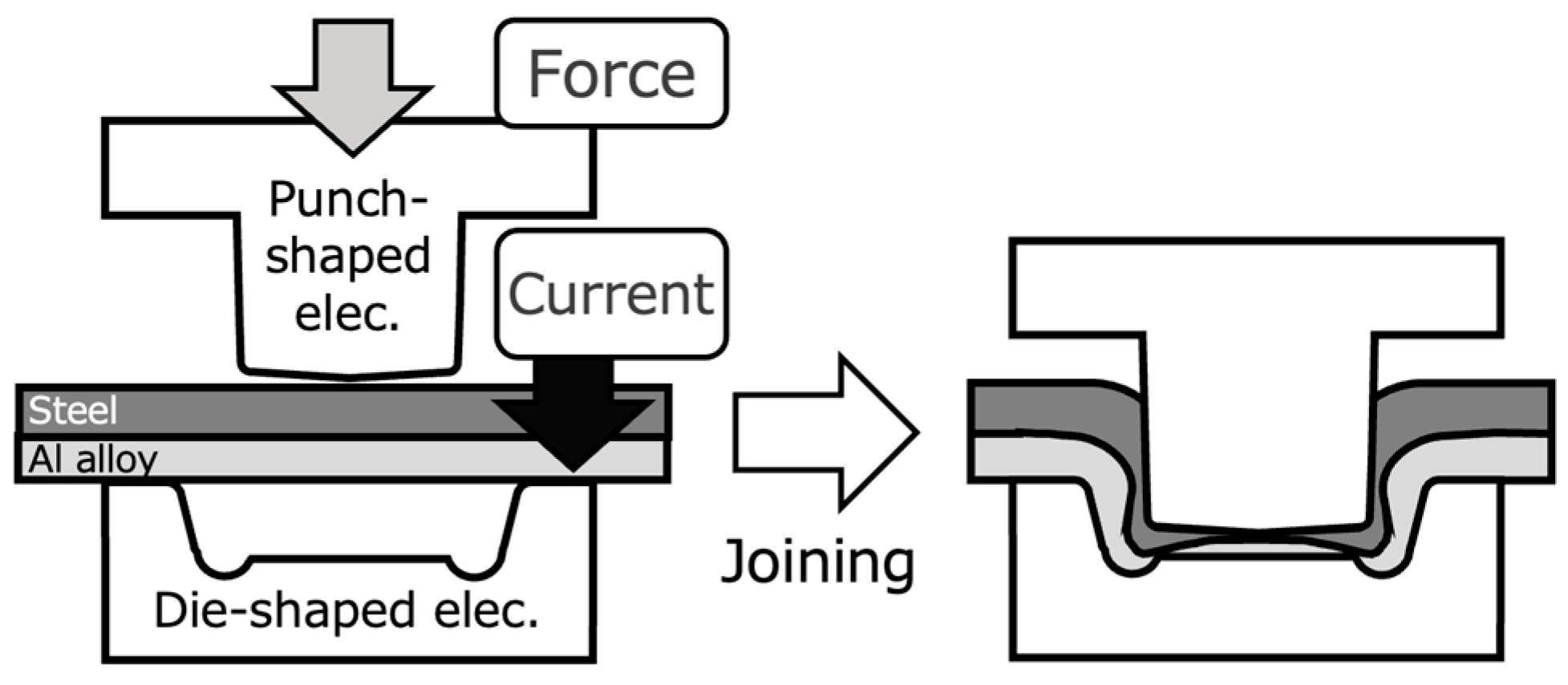
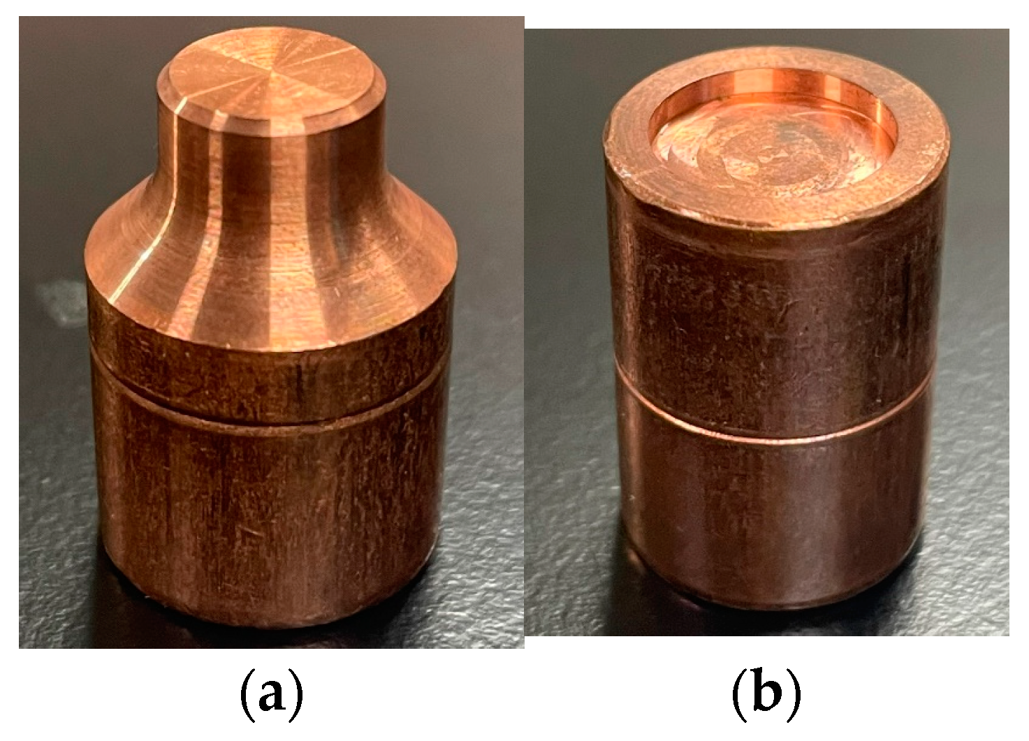
2.2. Joining Procedure

Stationary-type equipment was used for the resistance spot welding machine, and the power supply characteristics were DC inverter type. And the upper electrode is the positive electrode, and steel material was placed on the positive electrode side when joining was performed. The photographs of the die- and punch-shaped electrode used in this study are shown in Figure 2. These electrodes were machined from F-type electrodes made of aluminum dispersion strengthened copper. The electrodes were arranged with the punch electrode on the upper side and the die electrode on the lower side. Table 3 shows the joining conditions. A three-stage current process was used to reduce the thermal load on the electrodes to suppress electrode deformation caused by the rise in electrode temperature. For the current value of the third stage, a low current value that suppressed necking and peeling of the upper plate was used. The current time is the same for the 1st and 2nd current cycles to select the optimum conditions, while the current time for the 3rd current cycle is based on 15 cycles, which is longer than the 12 cycles and increased by 1 cycle up to 18 cycles. Cross-tension tests were conducted to evaluate the strength of the joints under the 3rd current cycle of 15 and 17. In addition, a joint with an R100 electrode was fabricated to compare its strength with that of a conventional electrode. It was confirmed that the joints used for the comparison of joint strength have the same IMC formation range.

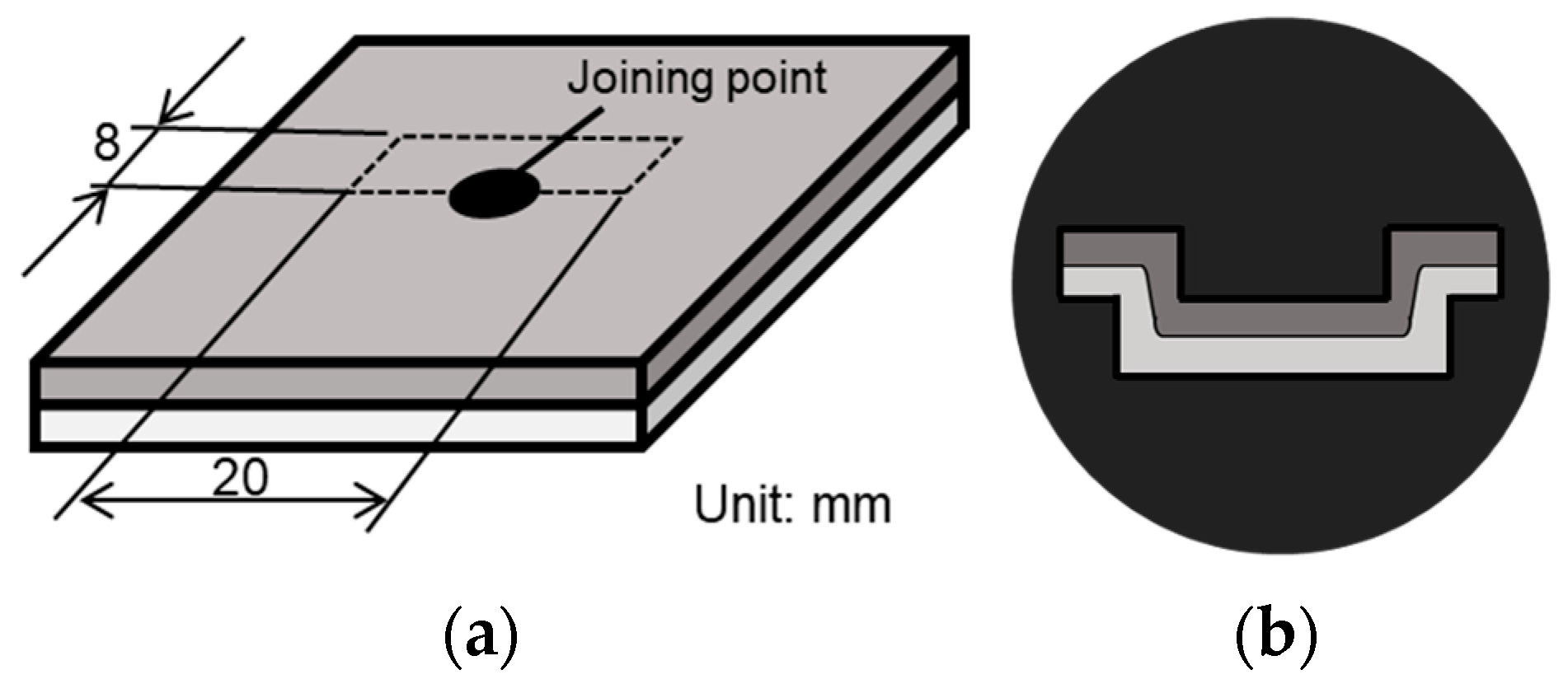
2.3. Method of Cross-Sectional Observation

A specimen for cross-sectional macro-observation was joined and cut with the dimensions shown in Figure 3a. Next, the specimens were embedded in resin using a molding machine as shown in Figure 3b and then polished with water-resistant abrasive paper #400, #800, #1500, and #2000. After that, mirror finishing was performed via buffing. Then, etching was performed using 3% nital as a corrosive solution with a corrosion time of about 15 s.

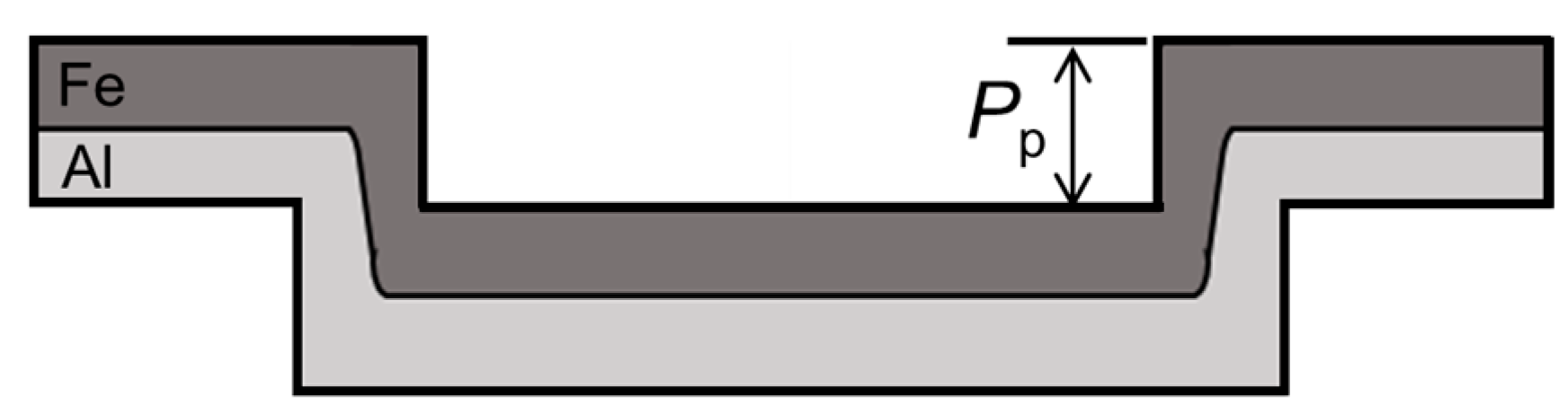
2.4. Method of Evaluation for Joint Deformation

Figure 4 shows the evaluation method for joint deformation. As shown in the figure, since joint deformation is caused by electrode push-in, the amount of electrode push-in was used as the target for evaluating joint deformation.

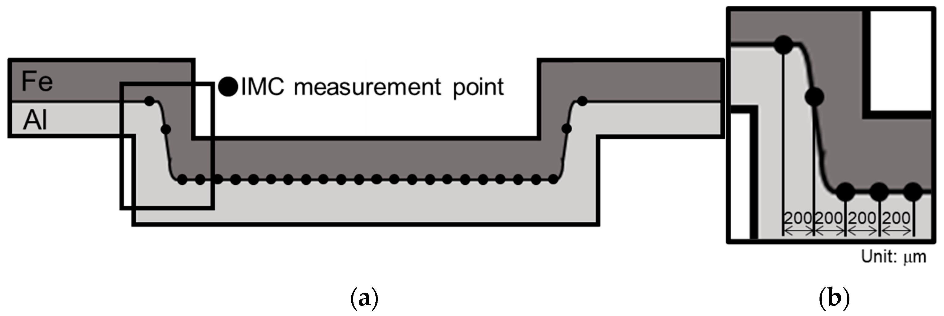
2.5. Method of Evaluation for IMC

To measure the IMC thickness, an OLYMPUS DSX510 digital microscope was used to observe the etched specimens at a magnification of 1500×. As shown in Figure 5, cross-sectional photographs were taken every 200 μm in linear distance from the end of the joint, and the IMC thickness distribution was calculated by measuring the IMC thickness at five points in each image and averaging the results.

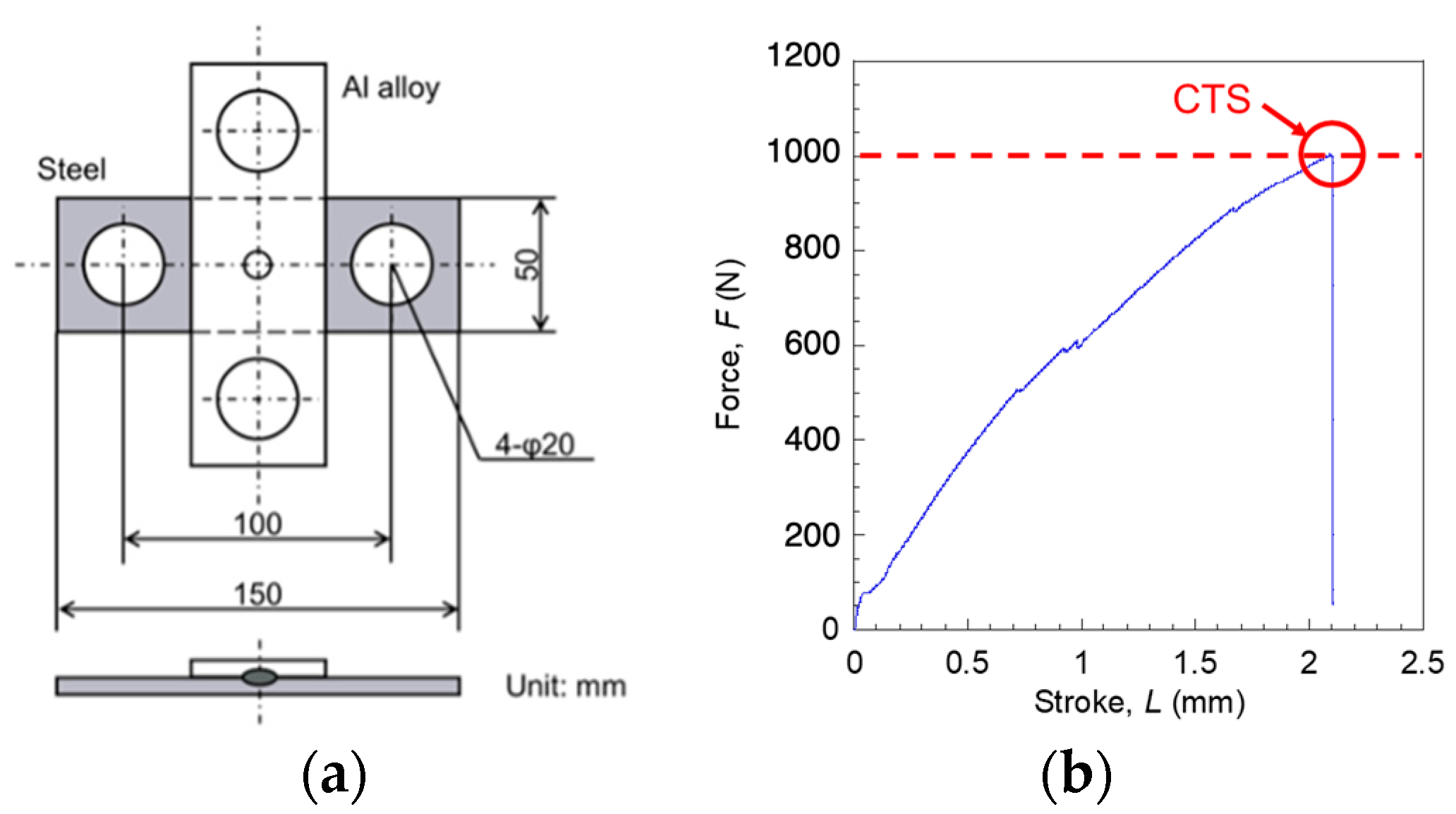
2.6. Method for Evaluation for Cross-Tension Strength

A cross-tension test was conducted to evaluate the joint strength in the peel direction of Fe–Al resistance spot welded joints using a die- and punch-shaped electrode. The cross-tension test specimens were fabricated by joining specimens with the dimensions shown in Figure 6a. The fabricated joints were then subjected to cross-tension tests. As shown in Figure 6b, the cross-tension strength (CTS) was defined as the value with the highest load among the load–displacement curves.

3. Results and Discussion

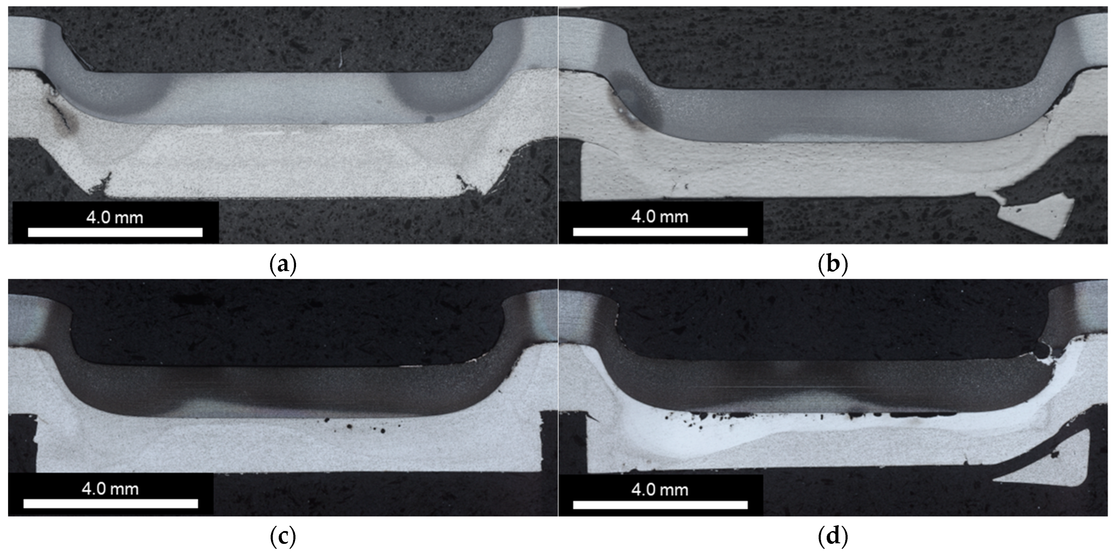
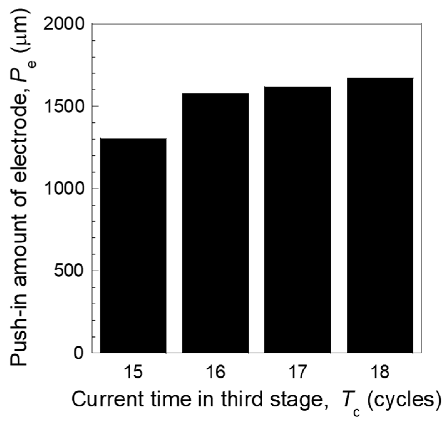
3.1. Effects of Electrode Shape and Third Current Cycle on Joint State and Joint Deformation

Figure 7 shows a macro-photograph of the joint cross section at each current time of the third cycle, and Figure 8 shows the amount of electrode push-in at each current time of the third cycle. First, as shown in Figure 7d, upper plate fracture is observed under the condition of 18 cycles, the longest current time. This is considered to be due to an increase in the electrode push-in amount with an increase in the current time. On the other hand, the condition of 17 cycles as shown in Figure 7c shows that the upper plate does not fracture. This indicates that the upper plate is considered to fracture when the 3rd cycle of the joining conditions used in this study exceeds 18 cycles. Under the 17 cycles condition shown in Figure 7c, the porosities in the lower plate and necking in the upper plate are not observed. The 15 kA condition shown in Figure 7a indicates that the degree of deformation of the joint is small. Focusing on the relationship between the current value of the third stage current and the electrode push-in amount in Figure 8, the deformation amount is smaller in the 15 kA condition than in the other conditions; however, the deformation amounts were similar in the other conditions.

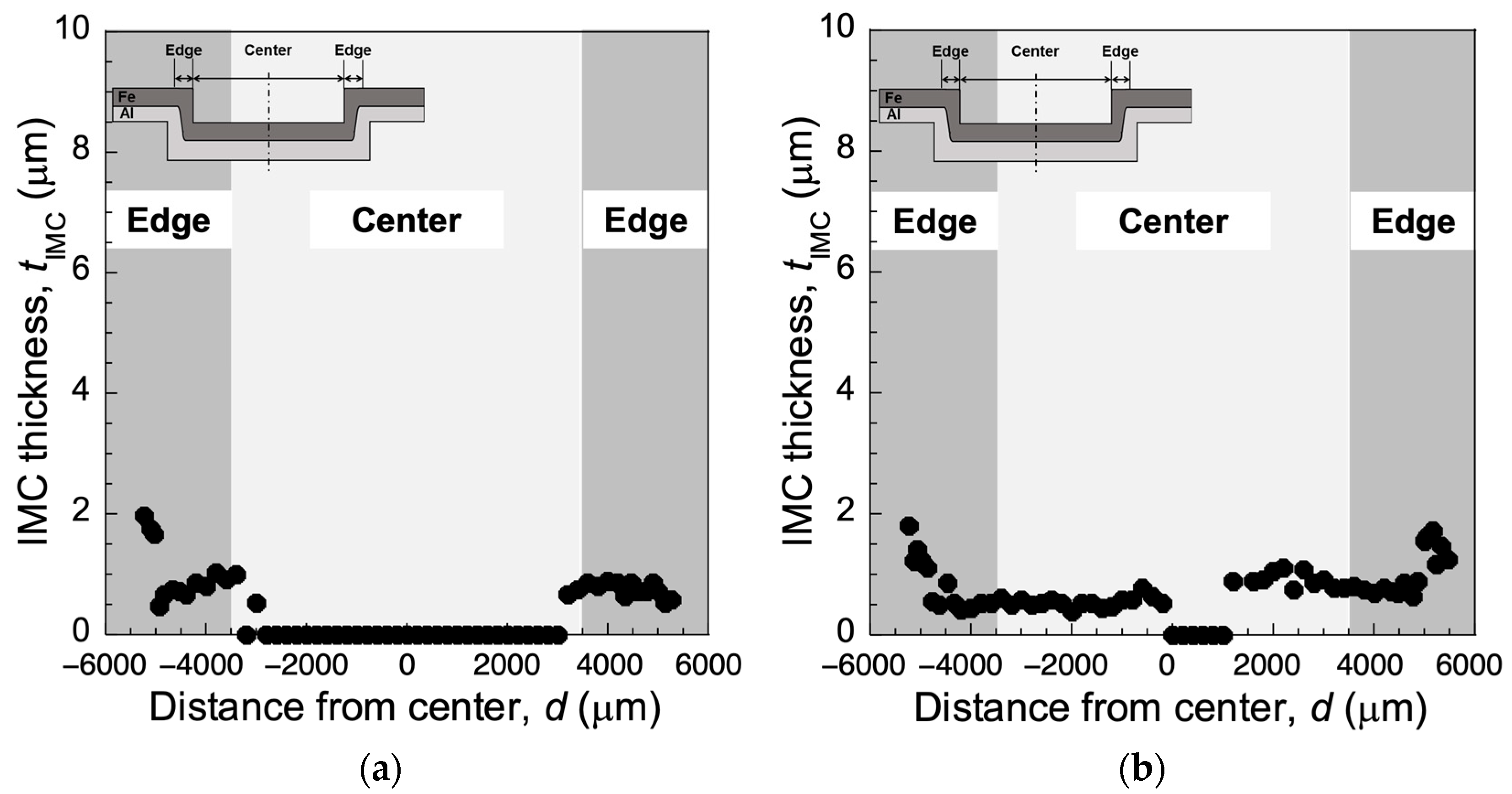
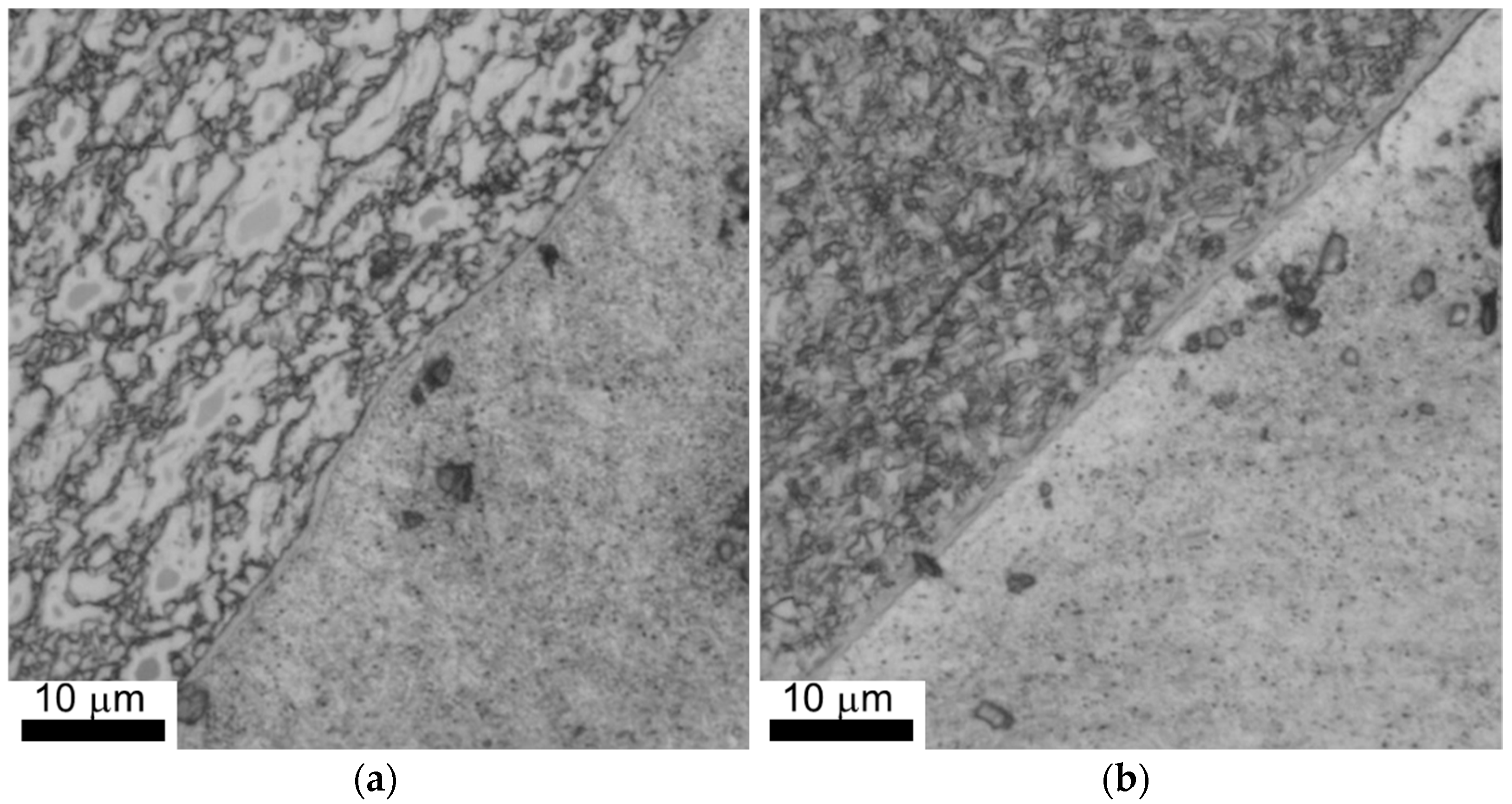
3.2. IMC Distribution

Figure 9 shows the IMC thickness distribution of the joints that are joined to low current for a long time. From the figure, it can be confirmed that all IMCs are formed thinner than 2 μm. For the 15 cycles condition shown in Figure 9a, IMCs are observed at the edge of the joint deformed in the thickness direction, while no IMCs are observed in the center. On the other hand, under the 17 cycles condition shown in Figure 9b, a thin IMC is formed from the end of the joint to the center of the joint, with some exceptions. This is due to the increase in the atomic diffusion time of Fe and Al caused by the increase in the current time. Figure 10 shows the state of IMC formation at the joint end deformed in the thickness direction. The figure shows that no spike-shaped IMCs are formed and that thin and uniform IMCs of less than 2 μm are formed. It is known that the shear strength of IMC is higher than the cross-tension strength. Therefore, it is considered that the formation of thin IMCs in the thickness direction can improve the cross-tension strength regardless of the presence of spiked IMCs.

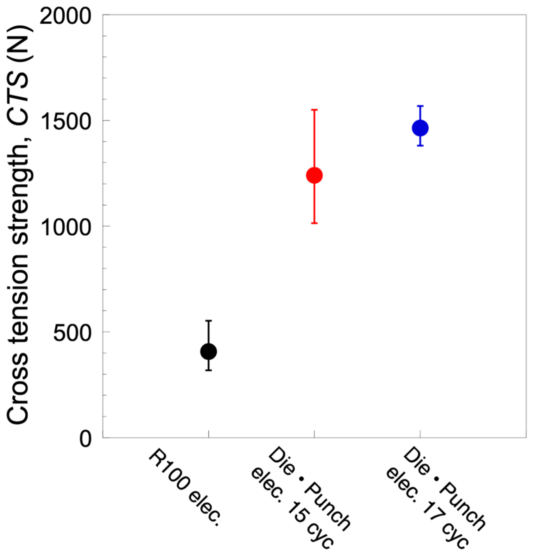
3.3. Cross-Tension Strength

Figure 11 shows the cross-tension strength results for each condition. As shown in Figure 11, it is confirmed that the CTS of the joint using the die- and punch-shaped electrodes increased compared to the joint using the R100 type electrode. In another study, it was confirmed that the IMC of the joints with R-type electrodes was formed horizontally to the plate. On the other hand, the IMCs of the joints using the die- and punch-shaped electrodes are formed in the direction of the plate thickness at the joint end. Furthermore, it is known that the shear strength of IMCs is higher than the cross-tension strength. In other words, it is considered that the joints with die- and punch-shaped electrodes have high CTS due to the shear load acting on the IMC formed in the thickness direction during the cross-tension test. Comparing the conditions using the die- and punch-shaped electrodes, it can be confirmed that the 17 cycles condition with a longer current time has a higher CTS. As shown in Figure 9, the IMC of the joint in 15 cycles is formed only at the end of the joint, while the IMC of the joint in 17 cycles is formed not only at the end of the joint but also at the center of the joint. In other words, the CTS is considered to have improved due to the expanded IMC formation area.
These results indicate that IMC formation in the thickness direction improves the cross-tension strength of Fe–Al dissimilar material resistance spot welded joints with die- and punch-shaped electrodes. Furthermore, it is suggested that the CTS is further improved by forming IMCs in the center of the joint in addition to the end of the joint.

4. Conclusions

In this study, a dissimilar material joining of high-strength steel sheet and aluminum alloy using die- and punch-shaped electrodes was investigated. First, it was found that resistance spot welding using die- and punch-shaped electrodes causes significant plastic deformation of the joint. Furthermore, it was clear that the deformation state changes as the current value was varied. The deformation was small when the current value was small, and the deformation became large when the current value was large; however, a phenomenon in which a part of the aluminum alloy melted was confirmed. The IMC condition under the low and appropriate current conditions showed that no IMC was formed in the center region of the joint under the low current condition. However, under the appropriate current condition, relatively thin IMCs of 2 μm or less were found to be distributed over the entire joining interface. Finally, the cross-tension strength of the joint was significantly improved compared to that of the conventional R-type electrode. From the above results, it can be concluded that the joining of dissimilar materials using die- and punch-shaped electrodes is an effective method for joining high-strength steel sheet and aluminum alloy.

Author Contributions

Conceptualization, M.I.; methodology, M.I and T.H.; validation, M.I., T.H. and Y.K.; investigation, M.I., T.H. and Y.K.; data curation, T.H. and Y.K.; writing—original draft preparation, M.I.; writing—review and editing, M.I.; visualization, T.H.; supervision, M.I.; project administration, M.I.; funding acquisition, M.I. All authors have read and agreed to the published version of the manuscript.

Funding

This research was supported by a scientific and technological research grant from the Suzuki Foundation.

Institutional Review Board Statement

Not applicable.

Informed Consent Statement

Not applicable.

Data Availability Statement

No new data were created or analyzed in this study. Data sharing is not applicable to this article.

Conflicts of Interest

The authors declare no conflict of interest.

References

  1. Zhang, W.; Sun, D.; Han, L.; Liu, D. Interfacial microstructure and mechanical property of resistance spot welded joint of high strength steel and aluminium alloy with 4047 AlSi12 interlayer. Mater. Des. 2014, 57, 186–194. [Google Scholar] [CrossRef]
  2. Arghavani, M.R.; Movahedi, M.; Kokabi, A.H. Role of zinc layer in resistance spot welding of aluminum to steel. Mater. Des. 2016, 102, 106–114. [Google Scholar] [CrossRef]
  3. Wan, Z.; Wang, H.P.; Chen, N.; Wang, M.; Carlson, B.E. Characterization of intermetallic compound at the interfaces of Al-steel resistance spot welds. J. Mater. Process. Technol. 2017, 242, 12–23. [Google Scholar] [CrossRef]
  4. Pan, B.; Shang, S.L.; Banu, M.; Wang, P.C.; Carlson, B.E.; Liu, Z.K.; Li, J. Understanding formation mechanisms of intermetallic compounds in dissimilar Al/steel joint processed by resistance spot welding. J. Manuf. Process. 2022, 83, 212–222. [Google Scholar] [CrossRef]
  5. Lara, B.; Giorjao, R.; Ghassemi-Armaki, H.; Ramirez, A. Fe-Al intermetallic suppression of dissimilar RSW joints using stainless-steel interlayers. Sci. Technol. Weld. Join. 2023, 28, 461–467. [Google Scholar] [CrossRef]
  6. Iyota, M.; Matsuda, T.; Sano, T.; Shigeta, M.; Shobu, T.; Yumoto, H.; Koyama, T.; Yamazaki, H.; Senba, Y.; Ohashi, H.; et al. A study on convection in molten zone of aluminum alloy during Fe/Al resistance spot welding. J. Manuf. Process. 2023, 94, 424–434. [Google Scholar] [CrossRef]
  7. Geng, P.; Morimura, M.; Ma, H.; Ma, Y.; Ma, N.; Liu, H.; Aoki, Y.; Fujii, H.; Qin, G. Elucidation of intermetallic compounds and mechanical properties of dissimilar friction stir lap welded 5052 Al alloy and DP590 steel. J. Alloys Compd. 2022, 906, 164381. [Google Scholar] [CrossRef]
  8. Zheng, M.; Yang, J.; Xu, J.; Jiang, J.; Zhang, H.; Oliveira, J.P.; Lv, X.; Xue, J.; Li, Z. Interfacial microstructure and strengthening mechanism of dissimilar laser al/steel via a porous high entropy alloy coating. J. Mater. Res. Technol. 2023, 23, 3997–4011. [Google Scholar] [CrossRef]
  9. Ma, Y.; Abe, Y.; Geng, P.; Akita, R.; Ma, N.; Mori, K. Adhesive dynamic behavior in the clinch-bonding process of aluminum alloy A5052-H34 and advanced high-strength steel JSC780. J. Mater. Process. Technol. 2022, 305, 117602. [Google Scholar] [CrossRef]
  10. Chen, C.; Kong, L.; Wang, M.; Haselhuhn, A.S.; Sigler, D.R.; Wang, H.P.; Carlson, B.E. The robustness of Al-steel resistance spot welding process. J. Manuf. Process 2019, 43, 300–310. [Google Scholar] [CrossRef]
  11. Zhang, Y.; Shan, H.; Li, Y.; Guo, J.; Luo, Z.; Ma, C.Y. Joining aluminum alloy 5052 sheets via novel hybrid resistance spot clinching process. Mater. Des. 2017, 118, 36–43. [Google Scholar] [CrossRef]
  12. Ren, D.; Zhao, D.; Liu, L.; Zhao, K. Clinch-resistance spot welding of galvanized mild steel to 5083 Al alloy. Int. J. Adv. Manuf. Technol. 2019, 101, 511–521. [Google Scholar] [CrossRef]
  13. Zhao, D.; Ren, D.; Song, G.; Zhao, K.; Zhang, Z. Nugget formation analysis of Al/Steel clinch-resistance hybrid spot welding. Sci. Technol. Weld. Join. 2021, 26, 439–447. [Google Scholar] [CrossRef]
Figure 1. Schematic illustration of joining process of resistance spot welding using die- and punch-shaped electrodes.
Engproc 43 00045 g001
Figure 2. Photographs of punch- and die-shaped electrodes: (a) punch-shaped electrode; (b) die-shaped electrode.
Engproc 43 00045 g002
Figure 3. Dimension and schematic illustration of specimen for cross-sectional observation: (a) schematic illustration of cutting method; (b) schematic illustration of molding specimen.
Engproc 43 00045 g003
Figure 4. Schematic illustration of evaluation length as a joint deformation.
Engproc 43 00045 g004
Figure 5. Schematic illustration of evaluation method of IMC: (a) outline of measurement points; (b) distance for each measurement point.
Engproc 43 00045 g005
Figure 6. Dimension of specimen for cross-tension test and schematic illustration of evaluation method for CTS: (a) schematic illustration of cross-tension test specimen; (b) schematic illustration of relationship between force and stroke during cross-tension test and evaluation point of CTS.
Engproc 43 00045 g006
Figure 7. Cross-sectional observation for each joining condition: (a) in case of 15 kA; (b) in case of 16 kA; (c) in case of 17 kA; (d) in case of 18 kA.
Engproc 43 00045 g007
Figure 8. Push-in amount of electrode for each joining condition.
Engproc 43 00045 g008
Figure 9. IMC distribution in case of 15 kA and 17 kA: (a) in case of 15 kA; (b) in case of 17 kA.
Engproc 43 00045 g009
Figure 10. Enlarged photographs of IMC: (a) in case of 15 kA; (b) in case of 17 kA.
Engproc 43 00045 g010
Figure 11. Cross-tension strength for each joining condition and comparison with CTS values of joints using conventional electrodes.
Engproc 43 00045 g011
Table 1. Chemical composition and mechanical properties of 590 MPa class high-strength steel sheet.
Chemical Composition (Mass %)Mechanical Properties
C
0.12
Si
0.29
Mn
1.41
P
0.009
S
0.005
YS (MPa)
516
TS (MPa)
522
El (%)
23
Table 2. Chemical composition and mechanical properties of A6061-T6 alloy.
Chemical Composition (Mass %)Mechanical Properties
Si
0.40~0.8
Fe
0.7
Cu
0.15~0.40
Mn
0.15
Mg
0.8~1.2
Cr
0.04~0.35
Zn
0.25
Ti
0.15
YS (MPa)
245
TS (MPa)
295
El (%)
10
Table 3. Joining conditions of varying electrical current time (1 cycle = 0.0167 s).
Electrode Combination
(Upper/Lower)
Electrical Current,
I (kA)
Current Time,
Tc (cycles)
Current Interval,
Ti (cycles)
Electrode Force,
F (kN)
Hold Time,
TH (cycles)
1st2nd3rd1st2nd3rd
Punch-shaped/
Die-shaped
131518121215243.76
16
17
18
R100/R1001612-3.76
Disclaimer/Publisher’s Note: The statements, opinions and data contained in all publications are solely those of the individual author(s) and contributor(s) and not of MDPI and/or the editor(s). MDPI and/or the editor(s) disclaim responsibility for any injury to people or property resulting from any ideas, methods, instructions or products referred to in the content.

