Proceeding Paper

Influence of Printing Parameters on the Dimensional Accuracy of Concave/Convex Objects in FDM Printing †

Faculty of Engineering and Mathematics, Bielefeld University of Applied Sciences, 33619 Bielefeld, Germany
*
Author to whom correspondence should be addressed.
Presented at the 3rd International Electronic Conference on Applied Sciences, 1–15 December 2022; Available online: https://asec2022.sciforum.net/.
Eng. Proc. 2023, 31(1), 40; https://doi.org/10.3390/ASEC2022-13811
Published: 5 December 2022
(This article belongs to the Proceedings of The 3rd International Electronic Conference on Applied Sciences)

Abstract

:
Three-dimensional printing belongs to the emerging technologies of our time. An important aspect regarding the potential applications of 3D-printed objects is their dimensional accuracy. Especially in the case of the most often used fused deposition modeling (FDM) technique, dimensional differences between the digital model and the printed object are common and depend not only on the printer’s accuracy, but also on the printing parameters as well as the chosen material. Here, we report on the dimensional accuracy of FDM-printed objects with sharp inner or outer corners, dependent on the printing parameters. We show that different adhesion assistants lead to a variation in the dimensional accuracy and that this can be used to optimize this parameter.

1. Introduction

Originally used for rapid prototyping, additive manufacturing technologies have long emerged into rapid tooling and production. While some of these 3D printing techniques necessitate highly sophisticated equipment and processes, even enabling metal additive manufacturing [1], polymer printing methods such as fused deposition modeling (FDM) or stereolithography (SLA) are most often used in the low-cost sector [2].
Generally, FDM printing and similar methods are highly suitable for the production of single objects with complicated shapes, enabling faster manufacturing of lightweight products [3,4]. On the other hand, the mechanical properties as well as the dimensional accuracy of such objects are often inferior to those produced by injection molding [5,6]. This is why several researchers have investigated possibilities to improve not only the mechanical properties [7,8], but also the dimensional accuracy of FDM-printed objects.
Nancharaiah et al., e.g., showed that a small layer thickness can improve the dimensional accuracy, while a negative air gap between neighboring strands—often used to improve the mechanical properties of FDM-printed parts—reduces the dimensional accuracy [9]. Garg et al. concentrated on postprocessing acrylonitrile butadiene styrene (ABS) parts by cold vapor treatment with acetone and found significantly improved surfaces at the cost of only small dimensional changes [10]. For ABS and poly(lactic acid) (PLA), Zharylkassyn et al. also suggested a small layer thickness of 0.1–0.2 mm, low extrusion temperatures and part orientations of 0° and 90°, while they also underlined the effect of the part geometry on the dimensional accuracy [11]. Comparing ABS and PLA specimens, Akbas et al. reported on a higher accuracy of PLA samples, while also mentioning an increase in the part dimensions with increasing printing temperature, but decreasing dimensions with increasing feed rate [12].
One factor which has scarcely been investigated is the adhesion assistants, i.e., brim, skirt and raft. While brim or raft are often suggested as a tool to avoid warping [13,14,15], their influence on the dimensional accuracy of specimens which could also be printed with a simple skirt is normally not described.
Here, we report on measurements of the dimensional accuracy for specimens with sharp inner or outer (concave and convex) corners, depending on the different adhesion assistants as well as other printing parameters, using FDM printing with PLA and ABS.

2. Materials and Methods

Specimens were printed by an Orcabot XXL (Prodim, Helmont, The Netherlands) with a nozzle diameter of 0.4 mm, nozzle temperature of 210 °C (PLA) or ABS (230 °C), printing bed temperature of 60 °C, layer thickness of 0.2 mm and 20% infill (linear, orientation ±45°). Printing materials were PLA (Filamentworld, Neu-Ulm, Germany) and ABS (Filamentworld). The printed samples had a width of 10 mm, a height of 5 mm and lengths of 100 mm (“long”) or 20 mm (“short”). The shapes are concave or convex, as shown in Table 1. Specimens were printed with a skirt (no contact to specimen), a brim (1 layer, 3 mm width, contact with specimen), or a raft (3 layers below the specimen which is printed in a distance of 0.2 mm, i.e., detachable from the specimen). All samples were printed in triplicates.
Dimensions were measured using a micrometer caliper (all values below 35 mm) or a vernier caliper, respectively. For angle measurements, microscopic images were taken using a digital optical microscope VHX-600D by Keyence (Neu-Isenburg, Germany), and the angles were evaluated using ImageJ 1.53e (National Institutes of Health, Bethesda, MD, USA).

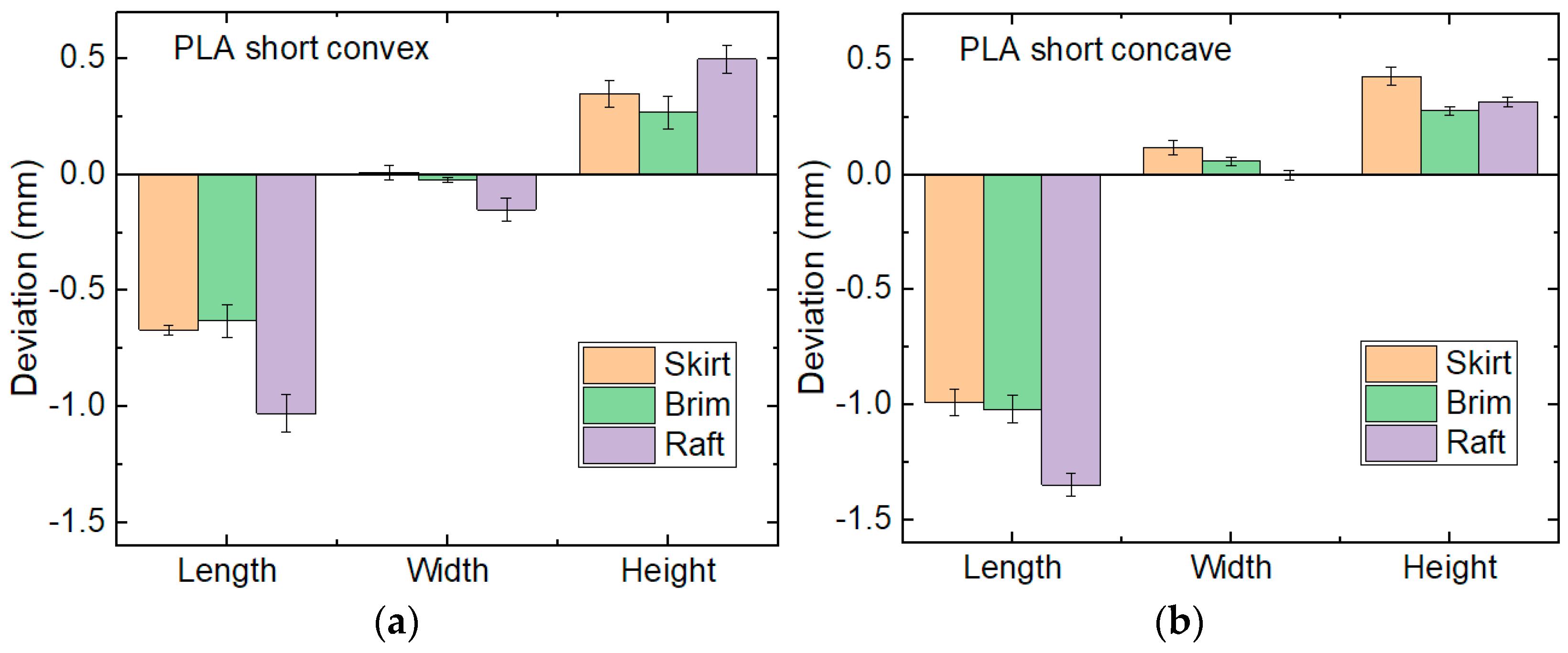
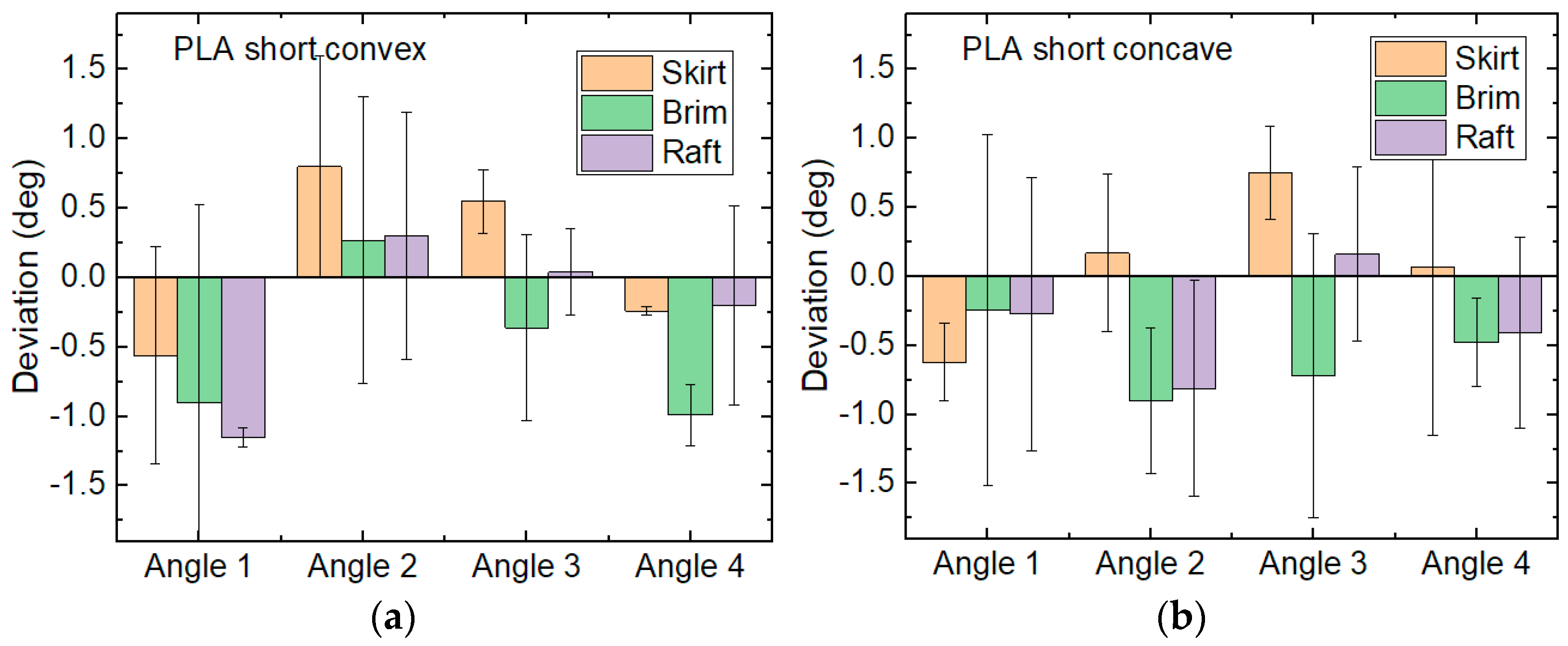
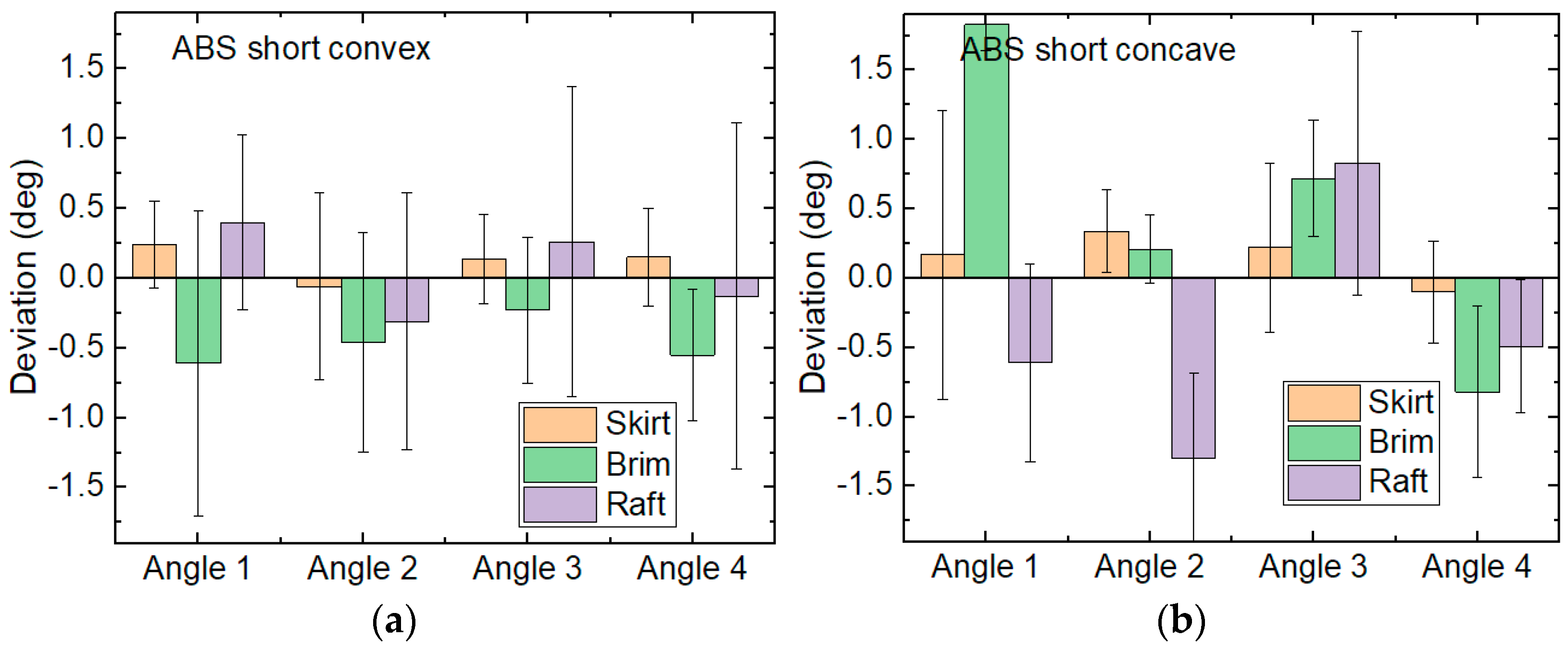
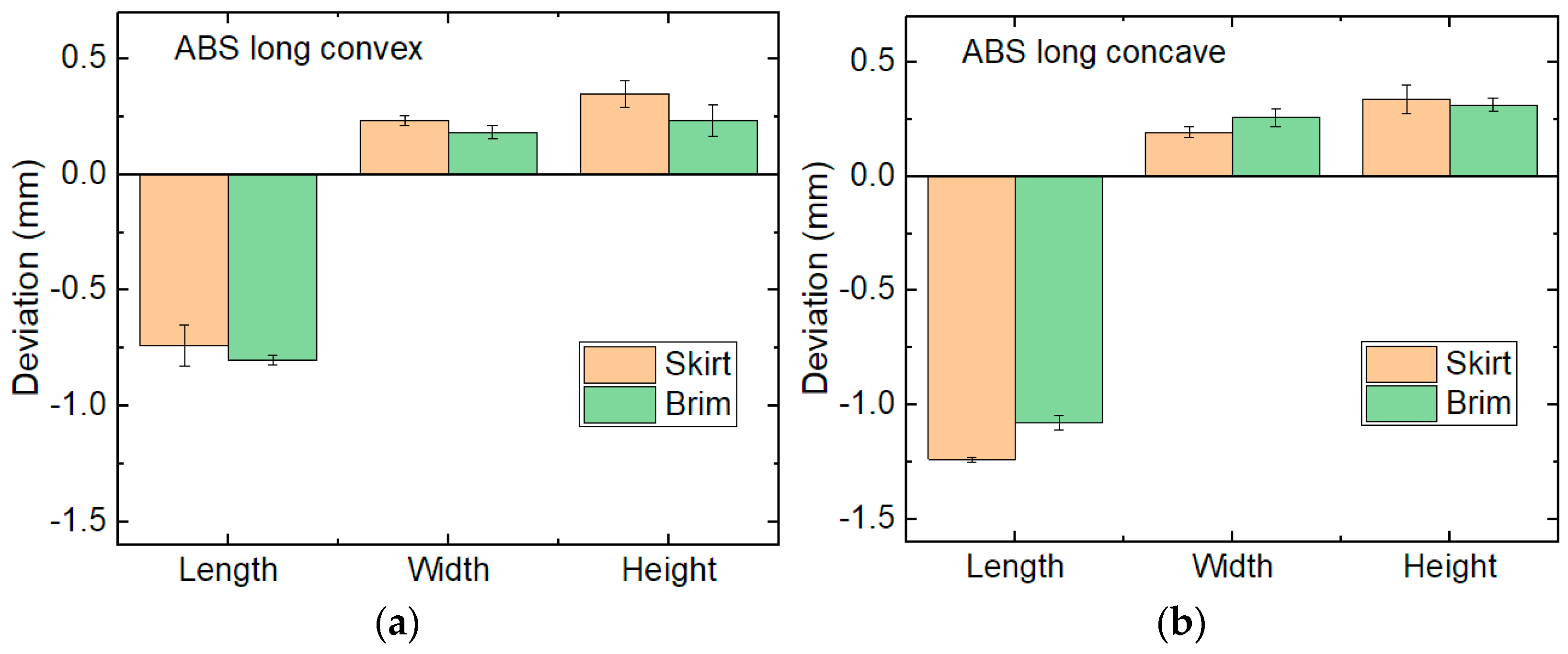
3. Results and Discussion

Generally, sharp corners are hard to print with the FDM technology, since the nozzle width defines the minimum detail width which can be printed. Figure 1 shows exemplarily short convex and concave specimens, printed from ABS. The undesired rounding of the inner and outer edges is clearly visible.
This effect does not change if a brim or raft is used as adhesion support, as Figure 2 shows exemplarily for convex specimens printed from ABS. Nevertheless, it can be expected that brim or raft will change the dimensional and angle accuracy.
Next, the dimensional deviations of the short PLA samples are compared. As Figure 3 shows, the heights are generally larger than in the CAD model, while the lengths are generally smaller than desired, and the widths are similar to the model. Regarding the lengths, a raft increases the deviation from the desired value as compared to skirt and brim, while no clear trend can be recognized regarding width and height. The stronger lengthwise shrinking of samples printed on a raft can be attributed to the more flexible adhesion on the raft as compared to the fixation on the printing bed, allowing for stronger relaxation upon cooling, as well as faster cooling due to the larger distance of the first layer to the heated printing bed.
The results of dimensional measurements on ABS samples are depicted in Figure 4. For this material, the length deviations are slightly smaller than for PLA, while the width deviations are slightly larger. For the concave specimens, printing with a brim is disadvantageous regarding widths and heights. For all other samples, no large differences between specimens printed with skirt, brim and raft are visible.
Next, the angles are measured for the aforementioned samples. Figure 5 depicts the values of the short PLA samples, with the angles defined as 1 (upper-left angle in Table 1), 2 (lower-left angle), 3 (upper-right angle) and 4 (lower-right angle), respectively. In most cases, the standard deviations are large enough to include a deviation of zero, so that no clear trends are visible. Correspondingly, no significant differences between the different adhesion assistants are visible.
For the samples printed from ABS, the results are similar, as Figure 6 shows. Again most deviations are compatible with zero. The few values for which this is not the case, according to their standard deviations—e.g., ABS short concave, Angle 1 of the specimens printed with a brim—do not show real deviations between measured and modeled angles, either. This can easily be recognized by imagining a rotation of the sample by 180° around the out-of-plane axis. Due to the infill orientation of ±45°, this is a symmetry operation for these samples, so that Angle 1 and Angle 4 should be identical, as well as Angle 2 and Angle 3. Comparing these pairwise nominally identical angles clearly shows large differences, suggesting that no systematic deviation of the measured angles from the modeled ones occurs here, but arbitrary deviations are responsible for the observed differences. The angles are thus not further taken into account in the examinations of the long samples.
For the long samples, widths and heights were measured at two positions per sample. The results for the PLA specimens, printed with skirt and brim, are depicted in Figure 7. Rafts were not further taken into account due to their high length deviations for PLA samples (cf. Figure 3). In both geometries, convex and concave, the deviations are quite similar to those found for the short samples, although the longer samples enable longer cooling times of previous layers before the subsequent layer is printed on it. While insufficient cooling durations of PLA layers are a well-known problem for objects with small lateral cross-sections, this problem does not seem to occur here; i.e., the short specimens are large enough to allow each layer to cool down before the next layer is started.
For ABS, on the other hand, the deviations of the measured lengths from the modeled ones are slightly larger than in case of the short specimens, as Figure 8 shows. This can be attributed to the well-known strong shrinkage of ABS upon cooling which often leads to warping for thicker samples. Width and height deviations are similar to those found for the short ABS samples, as expected.

4. Conclusions

ABS and PLA rectangular samples with additional concave or convex edges were FDM-printed and investigated in terms of dimensional and angular accuracy.
All in all, no clear impact of the adhesion assistant on the dimensional accuracy of 3D-printed PLA and ABS objects could be found. The measured angles did not show significant deviations from the modeled ones, in spite of the inaccuracies depicted in Figure 1 and Figure 2, which are based on the principle of the FDM technique and related to the used nozzle diameter. These results show that for similar dimensions and materials, the adhesion assistant can be freely chosen without impeding the desired dimensional accuracy. The small standard deviations of the geometrical deviations between printed samples and modeled shapes suggest that these deviations can be leveled out by investigating a test print and subsequently designing the model dimensions accordingly.

Author Contributions

Conceptualization, B.E.; methodology, B.E.; formal analysis, A.E.; investigation, B.E.; writing—original draft preparation, A.E.; writing—review and editing, B.E.; visualization, A.E. All authors have read and agreed to the published version of the manuscript.

Funding

This research received no external funding.

Institutional Review Board Statement

Not applicable.

Informed Consent Statement

Not applicable.

Data Availability Statement

All data produced in this study are included in the paper.

Conflicts of Interest

The authors declare no conflict of interest.

References

  1. Murr, L.E.; Gaytan, S.M.; Ramirez, D.A.; Martinez, E.; Hernandez, J.; Amato, K.N.; Shindo, P.W.; Medina, F.R.; Wicker, R.B. Metal Fabrication by Additive Manufacturing Using Laser and Electron Beam Melting Technologies. J. Mater. Sci. Technol. 2012, 28, 1–14. [Google Scholar] [CrossRef]
  2. Noorani, R. Rapid Prototyping: Principles and Applications; John Wiley & Sons: Hoboken, NJ, USA, 2005. [Google Scholar]
  3. Schmelzle, J.; Kline, E.V.; Dickman, C.J.; Reutzel, E.W.; Jones, G.; Simpson, T.W. (Re)Designing for Part Consolidation: Understanding the Challenges of Metal Additive Manufacturing. J. Mech. Des. 2015, 137, 111404. [Google Scholar] [CrossRef]
  4. Plocher, J.; Panesar, A. Review on design and structural optimisation in additive manufacturing: Towards next-generation lightweight structures. Mater. Des. 2019, 183, 108164. [Google Scholar] [CrossRef]
  5. Chen, Q.; Liu, J.K.; Liang, X.; To, A.C. A level-set based continuous scanning path optimization method for reducing residual stress and deformation in metal additive manufacturing. Comput. Methods Appl. Mech. Eng. 2020, 360, 112719. [Google Scholar] [CrossRef]
  6. Carpenter, K.; Tabei, A. On residual stress development, prevention, and compensation in metal additive manufacturing. Materials 2020, 13, 255. [Google Scholar] [CrossRef] [PubMed] [Green Version]
  7. Chalgham, A.; Wickenkamp, I.; Ehrmann, A. Mechanical properties of FDM printed PLA parts before and after thermal treatment. Polymers 2021, 13, 1239. [Google Scholar] [CrossRef] [PubMed]
  8. Wach, R.A.; Wolszczak, P.; Adamus-Wlodarczyk, A. Enhancement of mechanical properties of FDM-PLA Parts via thermal annealing. Macromol. Mater. Eng. 2018, 303, 1800169. [Google Scholar] [CrossRef]
  9. Nancharaiah, T.; Ranga Raju, D.; Ramachandra Raju, V. An experimental investigation on surface quality and dimensional accuracy of FDM components. Int. J. Emerg. Technol. 2010, 1, 106–111. [Google Scholar]
  10. Garg, A.; Bhattacharya, A.; Batish, A. On Surface Finish and Dimensional Accuracy of FDM Parts after Cold Vapor Treatment. Mater. Manuf. Process. 2016, 31, 522–529. [Google Scholar] [CrossRef]
  11. Zharylkassyn, B.; Perveen, A.; Talamona, D. Effect of process parameters and materials on the dimensional accuracy of FDM parts. Mater. Today Proc. 2021, 44, 1307–1311. [Google Scholar] [CrossRef]
  12. Abkas, O.E.; Hira, O.; Hervan, S.Z.; Samankan, S.; Altinkaynak, A. Dimensional accuracy of FDM-printed polymer parts. Rapid Prototyp. J. 2020, 26, 288–298. [Google Scholar]
  13. Loh, G.H.; Pei, E.; Gonzalez-Gutierrez, J.; Monzón, M. An overview of material extrusion troubleshooting. Appl. Sci. 2020, 10, 4776. [Google Scholar]
  14. Devicharan, R.; Garg, R. Optimization of the Print Quality by Controlling the Process Parameters on 3D Printing Machine. In 3D Printing and Additive Manufacturing Technologies; Kumar, L., Pandey, P., Wimpenny, D., Eds.; Springer: Singapore, 2019; pp. 187–194. [Google Scholar]
  15. Mwema, F.M.; Akinlabi, E.T. Surface Engineering Strategy. In Fused Deposition Modeling; Springer Briefs in Applied Sciences and Technology; Springer: Cham, Switzerland, 2020; pp. 51–68. [Google Scholar]
Figure 1. Short ABS samples, printed with a skirt: (a) concave; (b) convex. Scale bars indicate 1 mm.
Engproc 31 00040 g001
Figure 2. Short concave ABS samples, printed (a) with a brim; (b) on a raft. Scale bars indicate 1 mm.
Engproc 31 00040 g002
Figure 3. Length deviations of short PLA samples: (a) convex; (b) concave.
Engproc 31 00040 g003
Figure 4. Length deviations of short ABS samples: (a) convex; (b) concave.
Engproc 31 00040 g004
Figure 5. Angle deviations of short PLA samples: (a) convex; (b) concave.
Engproc 31 00040 g005
Figure 6. Angle deviations of short ABS samples: (a) convex; (b) concave.
Engproc 31 00040 g006
Figure 7. Length deviations of long PLA samples: (a) convex; (b) concave.
Engproc 31 00040 g007
Figure 8. Length deviations of long ABS samples: (a) convex; (b) concave.
Engproc 31 00040 g008
Table 1. Definition of different specimens printed for this study. Heights of 5 mm and widths of 10 mm are identical for all cases, while lengths are 100 mm (“long”) or 20 mm (“short”).
SpecimenConcaveConvex
LongEngproc 31 00040 i001Engproc 31 00040 i002
ShortEngproc 31 00040 i003Engproc 31 00040 i004
Disclaimer/Publisher’s Note: The statements, opinions and data contained in all publications are solely those of the individual author(s) and contributor(s) and not of MDPI and/or the editor(s). MDPI and/or the editor(s) disclaim responsibility for any injury to people or property resulting from any ideas, methods, instructions or products referred to in the content.

