1. Introduction
The usage of smart devices in human life has risen enormously throughout the last decade. These smart devices need advanced and efficient sensors for working operations [
1]. A gyroscope is one of those inertial sensors that is being used for sensing and controlling the rotational motion of these devices [
2,
3], and it is being extensively used in smartphones, digital cameras, military, biomedical, household, space applications, and so on. The timeline history of the MEMS vibrating gyroscopes is presented [
4].
Microelectromechanical systems (MEMS) with vibrating gyroscopes [
5,
6] are widely used inertial sensors. The MEMS vibrating ring gyroscope’s usage is increased because of its best mode matching, symmetrical design features, higher sensitivity, and robust design for space applications [
7,
8]. There are various MEMS vibrating ring gyroscopes discussed by Jia et al. [
9]. Cao et al. developed a double U-beam-shaped vibratory ring gyroscope with twenty-four control and tuning electrodes [
10].
We present a double-ring MEMS vibrating gyroscope comprising sixteen worm-shaped springs with higher sensitivity for space applications. The paper discusses the modeling results obtained using ANSYS software. The modal and harmonic analysis have been discussed, as well as the effectiveness of the worm-shaped support springs. The worm-shaped support springs provide robust characteristics for the gyroscope design.
2. MEMS Vibrating Ring Gyroscope
MEMS vibrating gyroscopes have vibratory systems that need to oscillate continuously at the given resonant frequency. The working principle of the gyroscope is comprised of two vibrational modes. One vibration mode is used for driving the vibrating structure, and the second vibration mode is used for sensing the rotational movement of that vibrating structure.
The basic MEMS vibrating ring gyroscope has comprised a vibrating proof mass “m” with eight support springs having two degrees of freedom. The vibrating ring gyroscope vibrates along the driving direction with an elliptical shape of the ring. The schematic diagram of the vibrating ring mass system is shown in
Figure 1.
The general equations of motion for vibrating gyroscopes are shown below. The driving motion equation is written as Equation (1), the equation of motion detection along the sensing direction is written as Equation (2), and the Coriolis motion equation is presented as Equation (3). The “
m” represents the proof of mass, the “
c” is the damping coefficient, the “
k” represents the spring constant, the “
x” represents motion along the driving direction, the “
y” represents the motion along the sensing direction, and the “
” represents the external rotation applied to the gyroscope. There
,
, and
are driving, sensing, and Coriolis forces applied to the gyroscope motion equations.
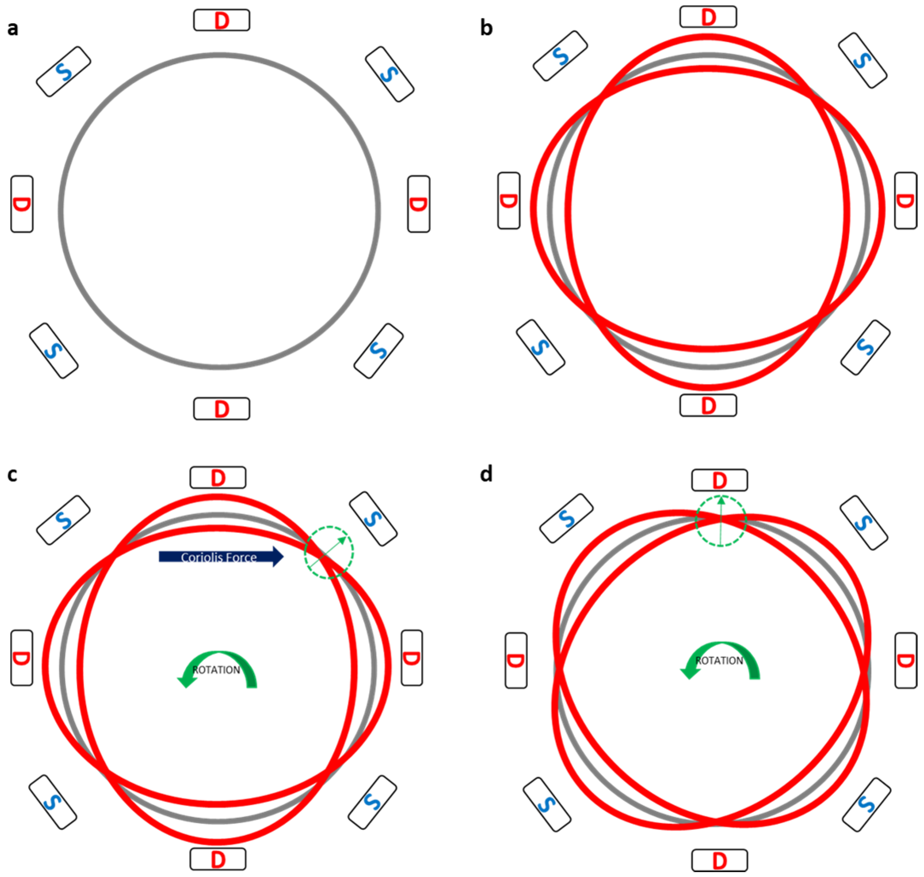
Basic Operating Mechanism
The basic operation of the vibrating ring gyroscope is described from steps a to d in
Figure 2. There are eight driving and sensing electrodes placed around the ring structure. Continuous oscillation and excitation are provided to the ring structure by driving electrodes at the set resonant frequency. The ring structure oscillates as an elliptical shape by driving electrodes along the driving axis. At the same time, there is no displacement along the sensing axis. However, when the gyroscope is exposed to external rotation, the Coriolis force generates and repels elliptical-shaped oscillations towards the sensing axis. The sensing electrodes sense the change in displacement.
3. Design Conceptualization
The proposed gyroscope design comprises double resonator rings, sixteen worm-shaped springs, and one centrally placed anchor. The sixteen worm-shaped springs were placed in two sets. The large sizes of the eight springs were placed with the internal set and attached to the internal ring and the centrally placed anchor. The small sizes of the eight springs are placed with the external set and attached to the external and internal rings of the gyroscope. The proposed vibrating ring gyroscope is shown in
Figure 3.
The concept of including two sets of sixteen worm-shaped springs enhances the gyroscope’s sensitivity and resistance to high-shock environments. The symmetric design of the proposed springs corroborates the need for high shock absorbers in harsh environments. The gyroscope design must be robust enough to operate in the space environment and provide excellent performance for space applications. The complete design features of the proposed vibrating ring gyroscope are listed in
Table 1. We have set the radius of the external ring resonator to 1000 µm, the reason to set this radius is to achieve an operating resonant frequency within the range of double-digit kHz. If we decrease the device size, the gyroscope’s operational resonant frequency will be higher. Therefore, higher resonant frequencies provide a large split resonant frequency of up to 100 s of kHz between driving and sensing resonant frequencies. If we increase the radius of the ring, then the operating resonant frequency will be lower, which means we need to increase the device size. Most of the MEMS vibrating gyroscopes operate at double-digit kHz resonant frequencies.
4. Modelling Analysis of Worm-Shaped Springs Vibrating Ring Gyroscope
Modal Analysis
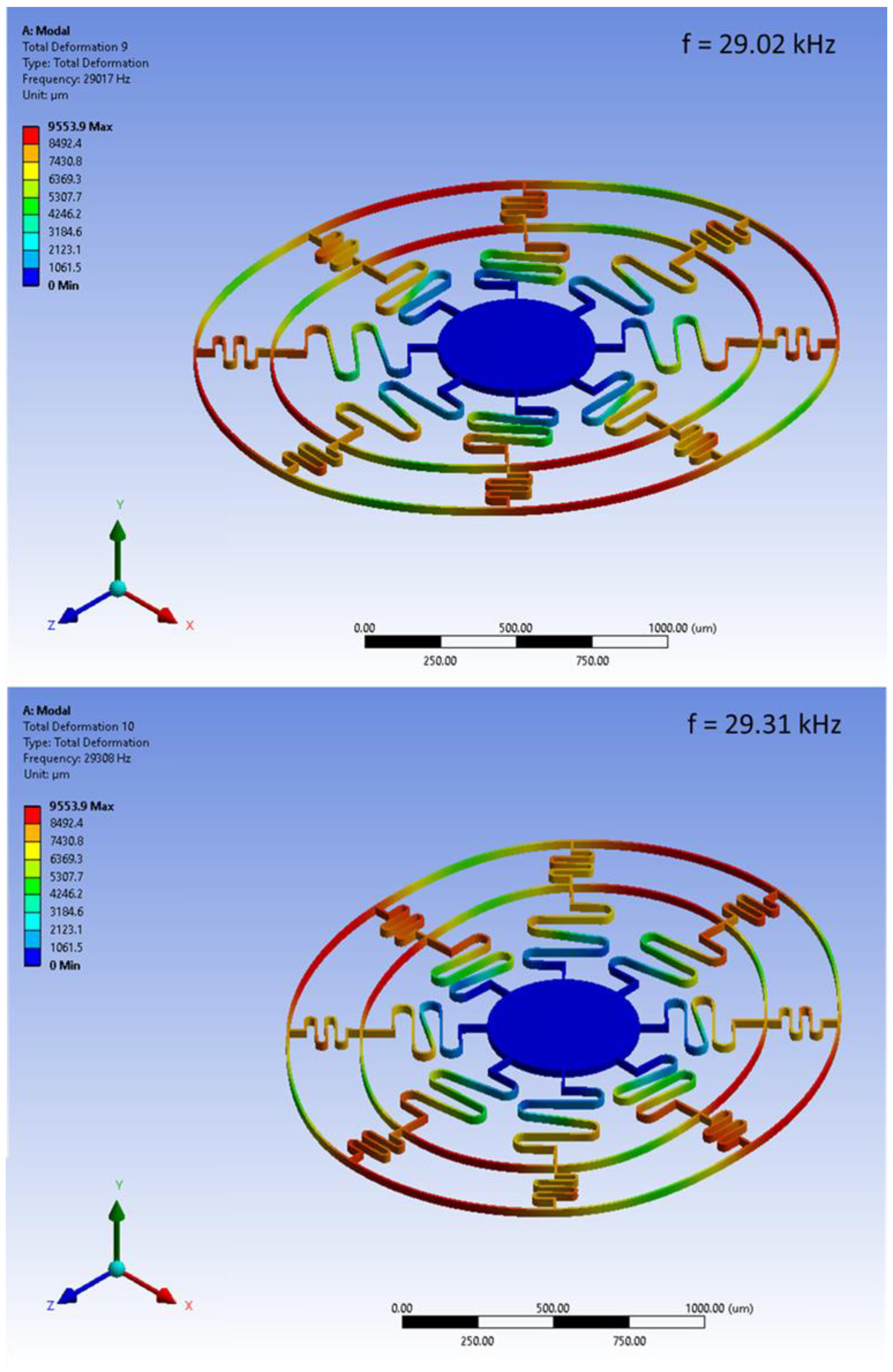
The finite element analysis of the proposed design has been conducted using the ANSYS software. The modal analysis describes the basic vibrational shapes of the selected design structure. The modal analysis provides information regarding natural frequencies, different vibrational shapes, structure displacement, and the vibration stability of the structure. The modal frequencies for mode n = 1 are shown in
Figure 4. The elliptical shapes of vibrations for the vibrating ring gyroscope can be seen in
Figure 4.
The driving and sensing resonant frequencies were measured at 29.07 kHz and 29.35 kHz, respectively. The frequency mismatch between driving and sensing resonant frequencies is recorded at 0.38 kHz.
5. Conclusions
This paper successfully demonstrated the initial development of the new worm-shaped spring vibrating ring gyroscope. Including two rings with sixteen worm-shaped springs enhances the performance reliability of the gyroscope for space applications. The 480 µm and 240 µm lengths of internal and external springs provide a higher compliance number, which shows a good response as a shock absorber. The vibrating ring radius is 1000 µm, with two elliptical shapes of resonant frequencies at 29.07 kHz and 29.35 kHz, respectively. The mode mismatch is recorded at 0.38 kHz. The proposed gyroscope design will be fabricated and dynamically tested for further investigation for space applications.
Author Contributions
The conceptualization and idea given by W.A.G.; All the figure design, findings, and preparation performed by W.A.G.; Writing: the draft was written by W.A.G.; Writing: review and editing of the final draft was performed by I.H., I.M. and K.M. All authors have read and agreed to the published version of the manuscript.
Funding
This research received no external funding.
Institutional Review Board Statement
Not applicable.
Informed Consent Statement
Not applicable.
Data Availability Statement
Not applicable.
Conflicts of Interest
The authors declare no conflict of interest.
References
- Mohammed, Z.; Gill, W.A.; Rasras, M. Double-comb-finger design to eliminate cross-axis sensitivity in a dual-axis accelerometer. IEEE Sens. Lett. 2017, 1, 1–4. [Google Scholar] [CrossRef]
- Xia, D.; Yu, C.; Kong, L. The Development of Micromachined Gyroscope Structure and Circuitry Technology. Sensors 2014, 14, 1394–1473. [Google Scholar] [CrossRef] [PubMed] [Green Version]
- Lee, J.S.; An, B.H.; Mansouri, M.; Al Yassi, H.; Taha, I.; Gill, W.A.; Choi, D.S. MEMS vibrating wheel on gimbal gyroscope with high scale factor. Microsyst. Technol. 2019, 25, 4645–4650. [Google Scholar] [CrossRef]
- Gill, W.A.; Howard, I.; Mazhar, I.; McKee, K. A Review of MEMS Vibrating Gyroscopes and Their Reliability Issues in Harsh Environments. Sensors 2022, 22, 7405. [Google Scholar] [CrossRef]
- Pistorio, F.; Saleem, M.M.; Somà, A. A Dual-Mass Resonant MEMS Gyroscope Design with Electrostatic Tuning for Frequency Mismatch Compensation. Appl. Sci. 2021, 11, 1129. [Google Scholar] [CrossRef]
- Hyun An, B.; Gill, W.A.; Lee, J.S.; Han, S.; Chang, H.K.; Chatterjee, A.N.; Choi, D.S. Micro-electromechanical vibrating ring gyroscope with structural mode-matching in (100) silicon. Sens Lett. 2018, 16, 548–551. [Google Scholar] [CrossRef]
- Gill, W.A.; Ali, D.; An, B.H.; Syed, W.U.; Saeed, N.; Al-shaibah, M.; Elfadel, I.M.; Al Dahmani, S.; Choi, D.S. MEMS multi-vibrating ring gyroscope for space applications. Microsyst. Technol. 2020, 26, 2527–2533. [Google Scholar] [CrossRef]
- Syed, W.U.; An, B.H.; Gill, W.A.; Saeed, N.; Al-Shaibah, M.S.; Al Dahmani, S.; Choi, D.S.; Elfadel, I.A.M. Sensor Design Migration: The Case of a VRG. IEEE Sens. J. 2019, 19, 10336–10346. [Google Scholar] [CrossRef]
- Jia, J.; Ding, X.; Qin, Z.; Ruan, Z.; Li, W.; Liu, X.; Li, H. Overview and analysis of MEMS Coriolis vibratory ring gyroscope. Measurement 2021, 182, 109704. [Google Scholar] [CrossRef]
- Cao, H.; Liu, Y.; Kou, Z.; Zhang, Y.; Shao, X.; Gao, J.; Huang, K.; Shi, Y.; Tang, J.; Shen, C.; et al. Design, fabrication and experiment of double U-beam MEMS vibration ring gyroscope. Micromachines 2019, 10, 186. [Google Scholar] [CrossRef] [PubMed] [Green Version]
| Disclaimer/Publisher’s Note: The statements, opinions and data contained in all publications are solely those of the individual author(s) and contributor(s) and not of MDPI and/or the editor(s). MDPI and/or the editor(s) disclaim responsibility for any injury to people or property resulting from any ideas, methods, instructions or products referred to in the content. |
© 2022 by the authors. Licensee MDPI, Basel, Switzerland. This article is an open access article distributed under the terms and conditions of the Creative Commons Attribution (CC BY) license (https://creativecommons.org/licenses/by/4.0/).


