1. Introduction
Reconfigurable UAVs are a new type of UAV that can use adaptive morphology, which involves changing the shape of the vehicle during flight to accomplish a specific task in a unique environment [
1]. Rotors/arm: tiltable, steerable, rotatable, reconfigurable, transformable, convertible, unconventional [
2], multirotors: foldable [
3], with rotating arms, with changeable dimensions, and so on.
The authors developed a transformable multirotor with two-dimensional multiple bonds in references [
3,
4]. The latter has a unique architecture that allows it to completely change its morphology.
Different approaches have been proposed in the literature for the different types of quadrotors such as PID (the Proportional-Integral-Derivative) in [
5,
6,
7,
8,
9], the linear quadratic [
10]; feedback linearization [
11,
12,
13], fuzzy logic (FL) control [
14], Backstepping [
15,
16], and control by sliding mode [
17,
18,
19].
In [
20,
21] proposed a classical PID for a tilting body multirotor that can switch to a vertical configuration. Scientists used an adaptive PID controller to control a foldable quadrotor in reference [
22].
Other authors created a multi-link foldable quadrotor based on the Linear Quadratic Integral (LQI) [
2]. The author investigated the use of Linear Quadratic Regulation (LQR) on a foldable quadrotor in [
3]. The authors proposed a nonlinear controller of a rotor quadrotor based on feedback linearization in [
23]. In [
24], an optimal gain scheduling backstepping controller based on a Particle Swarm Optimization (PSO) algorithm will be designed and tested for a Transformable Quadrotor. A new design with generic modeling and an adaptive backstepping controller of a transformable quadrotor can be found in [
25].
The main contribution of this work is the optimal MIMO-SMC for the flight stability and rapid convergence of variable states of a new reconfigurable UAV in finite time. Furthermore, the MIMO-SMC’s robustness will be tested against the uncertain parameters of the variable drone geometry. The primary control architecture is based on selecting between the various flight configurations. The gains of the MIMO-SMC controllers are obtained by using the Ant Colony Optimization (ACO) algorithm to minimize the error and energy criterion and establish which configuration consumed less energy.
The rest of the paper is structured as follows:
Section 2 presents the reconfigurable UAV description and modeling.
Section 3 explains the Integral Sliding Mode Controller (MIMO-SMC) design, and
Section 4 describes the Ant Colony Optimization algorithm.
Section 5 and
Section 6 present the simulation results as well as their interpretation.
Section 7 examines a comparison of flight configurations.
Section 8 is concerned with the conclusion and future works.
2. The Reconfigurable UAV Description and Modeling
The reconfigurable quadrotor has a very complex structure due to the change in configuration each time it adapts to a new morphology by slightly rotating the arms in [
25].
2.1. The Reconfigurable UAV’s Description
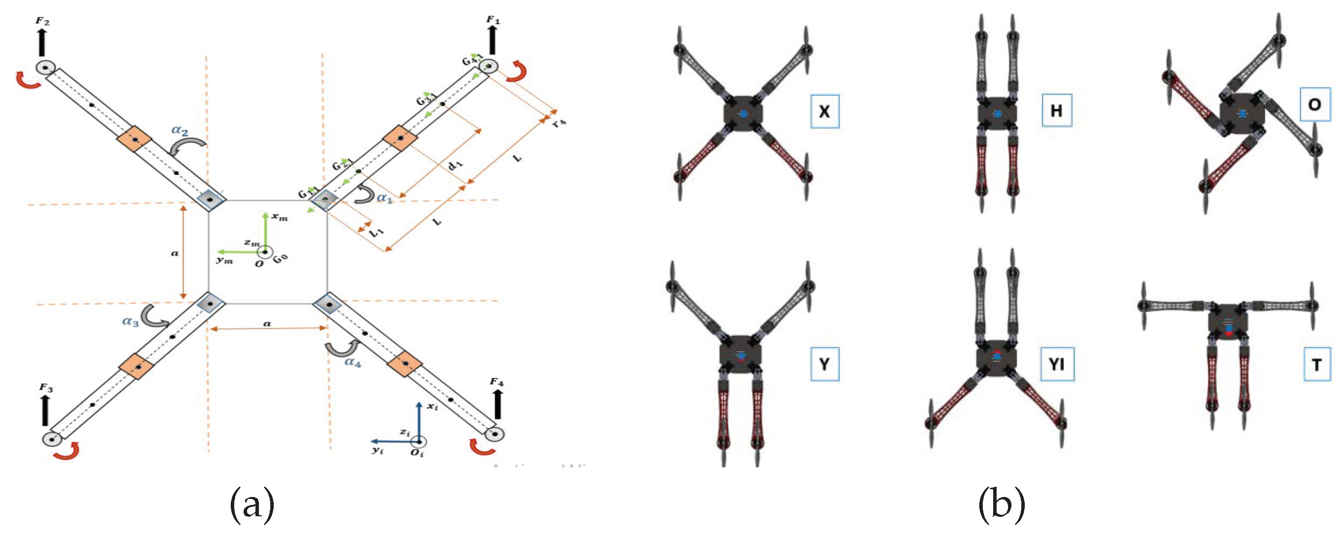
In this section, we will establish a reconfigurable UAV with four rotating arms that bend independently around the central body while keeping the angle of rotation
, using servomotors to allow for quick transitions between different configurations. To avoid propeller collisions, as shown in
Figure 1a, six morphologies are used, as depicted in
Figure 1b and
Table 1.
The angles of the arms can vary independently during each rotation of the arms, which means the quadrotor’s configuration changes, the center of gravity moves, and the inertia matrix and roll and pitch moments, in this case, change based on the arm orientations.
To perform a specific task in a specific area, our quadrotor’s configuration changes, it adopts an adaptive morphology to that task, and it can transform from the classic configuration “X” to other specific configurations by rotating or extending its arms.
2.2. The Reconfigurable UAV’s Modeling
When the configuration changes, the global position of the CoG changes. As a result, the inertia matrix , roll and pitch , moments, in this case, vary based on the arm angles . The linear and the angular velocity vectors of the body in the mobile frame are represented, respectively: and . Let describe the orientation of the mobile and denote its position in the fixed frame .
The relation between the velocities and the external forces
and moments
applied to
can be presented using the Newton–Euler formalism as:
2.3. Control Matrix
The control matrix
transforms the angular speeds of the propellers
to a total thrust force
and moments
. It can be represented as follows:
where
b and
d are the thrust and drag coefficients, respectively, and
are the CoG coordinates of the rotors.
The relation between the total thrust force, the moments applied to CoG and propeller square velocities is expressed as follows:
The proposed UAV has twelve control inputs, where
,
are used for the control of its altitude and attitude, while
control the arms rotation. The model used to design the controller is given by Equation (
4) as:
While and .
Using Equations (
1) and (
4), the simplified control model can be determined as Equation (
8). The state vector is given as:
such as:
where:
3. The Reconfigurable UAV’s Control
3.1. Control Structure
The variable parameters of the reconfigurable drone are characterized by the change in its structure. Furthermore, the proposed MIMO-SMC will be applied and tested in the presence of these uncertain parameters, such as CoG, inertia, arm angles and control matrix, to ensure that the state variables converge rapidly towards the sliding surface and, ultimately, the equilibrium point in finite time.
The rotation of the servomotors close to the main body causes the arms to vary by angles , whereas the rotation of the servomotors is attached to the primary arms . There are blocks that generate the desired trajectories (, , and ). Our UAV’s attitude and translations are controlled in two ways: by varying the position of the arms or the angular speeds of the four rotors. The two controls and are employed to calculate the desired roll and pitch angles. The servomotors that rotate the arms are controlled by PID controllers as follows:
3.2. MIMO Sliding Mode Control (MIMO-SMC) Design
This subsection describes the robust nonlinear controller design for a new reconfigurable UAV.
The sliding mode approach for MIMO nonlinear input-output systems has been proposed in [
26]. To the best of our knowledge, this approach has never been applied for quadrotors. To do so, we follow the steps below:
The state space model of UAV Equation (
8) is written as generalized canonical;
Sliding surfaces are chosen as Hurwitz polynomials;
Sliding reachability conditions are selected;
The highest-order derivatives of the control are obtained from the reachability condition.
We will go through the following procedures to synthesise the control law: We split our model state space of UAV Equation (
8) into six subsystems, we write each subsystem in the form of differential input/output equations, we take the first subsystem
The sliding surface is chosen as Hurwitz Polynomials, so we obtain the Sliding surface as follows:
Using the candidate Lyapunov function:
, which leads to
, which is the necessary condition of sliding, is required to ensure stability in the Lyapunov sense. The following is how we decide on the attractiveness condition:
As a result of inserting what we need in the previous Equation (
13), the control law derivatives are:
where
and
are positive parameters.
We repeat the previous steps to demonstrate asymptotic stability and extract the other controllers.
4. Optimization
We decided to employ optimization techniques because choosing parameters took a long time due to guesswork. We will propose a metaheuristics-based optimization technique and use it to identify the optimum control law parameters that were previously synthesized. Ant Colony Optimization (ACO) is used to obtain optimal parameters of the MIMO Sliding Mode Controller in [
27,
28].
For the creation of probable good solutions, ACO uses a pheromone matrix
, and
is the initial value of this matrix. The probability
of selecting a node
j at node
i is given by Equation (
15).
Heuristic functions are represented by:
a and
b are constants that govern the pheromone and heuristic values’ proportionate influence on the ant’s decision.
is the path taken by the ant
A. The amount of pheromone
on each path can be calculated as follows:
denotes the value of the A ant’s objective function.
is the best response that the ants have established up to the present iteration. Pheromone dissipation is a method of preventing an infinite rise in real ants. It also enables the forgetting of negative decisions.
where
is the number of ants, and
P is the evaporation rate
. Using the optimization approach mentioned in the previous paragraph, we explore optimization in the situation of search parameter’s optimal control laws applied to the quadrotor. To do so, we use the control laws from section three and modify them.
The number of iterations is set at 100, and we take the performance criteria for optimizing the energy supplied by the controller
and the mean quadratic error
, where:
5. Simulation Results
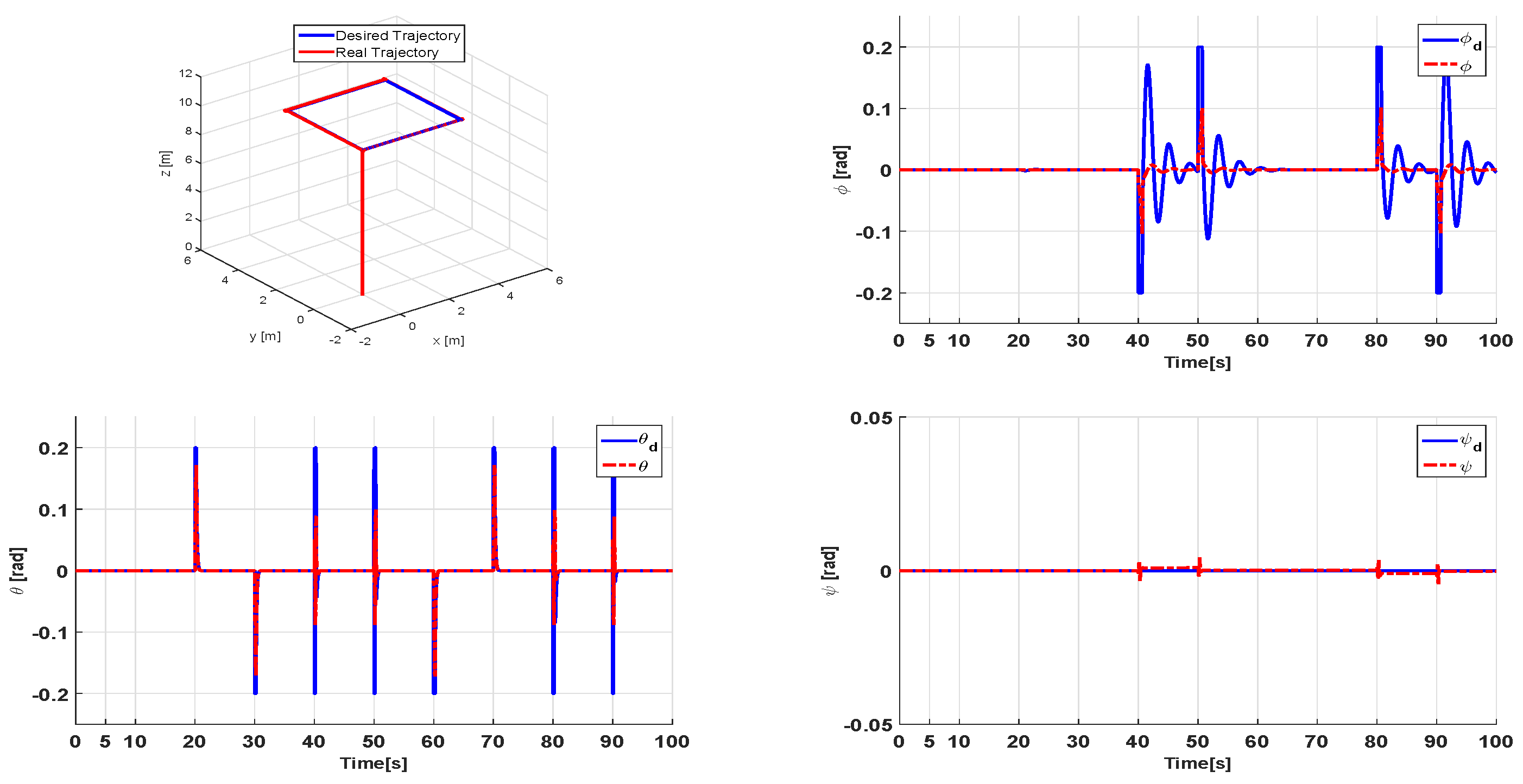
We will perform a flight scenario to assess the efficiency of the proposed controller for reconfigurable UAV attitude and altitude stabilization, which are implemented and discussed in this section. We used the Simulink/Matlab code to create a trajectory scenario (square). Our proposed UAV will follow each trajectory with different morphologies (
Table 1). Because of the figures’ large number, we chose just two configurations. The first will be in the form “
”, and the second will be in the form “
, as shown in
Figure 2,
Figure 3,
Figure 4 and
Figure 5.
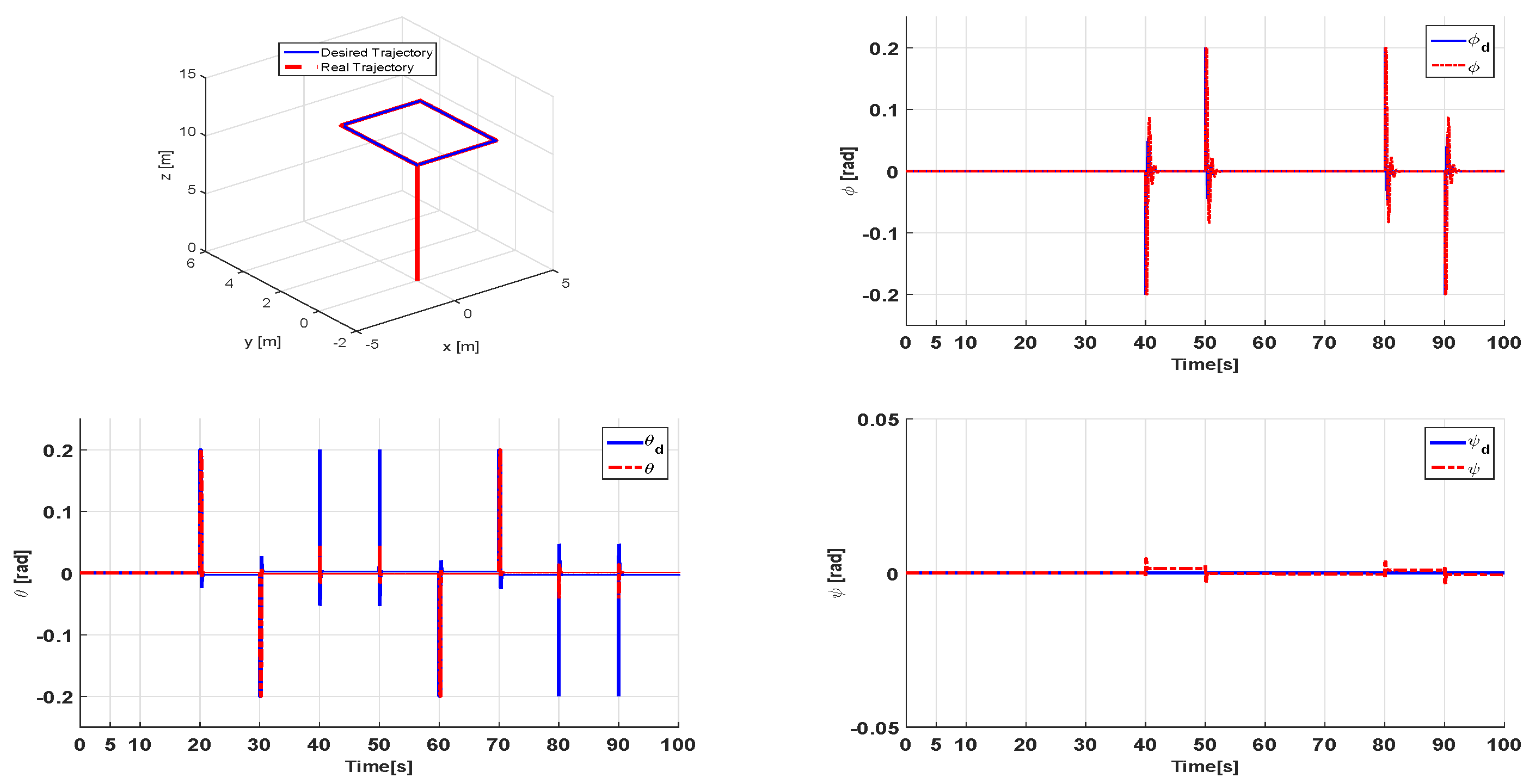
6. Results Interpretation
Figure 2 and
Figure 4 show that the reconfiguration can follow the desired trajectory for two scenarios and for the two configurations. We observe some errors along the three axes at first (
x,
y,
z) for the “
” configuration compared to the “
” configuration. The system’s responses for MIMO-SMC show the rapid convergence of variable states (
x,
y,
z) to their reference states (
,
,
) in finite time. We also observe a good tracking of Euler angles (
,
,
) to their desired attitude (
,
,
). We can also notice that once the desired positions and attitudes are reached, the errors in position and attitude converge to zero.
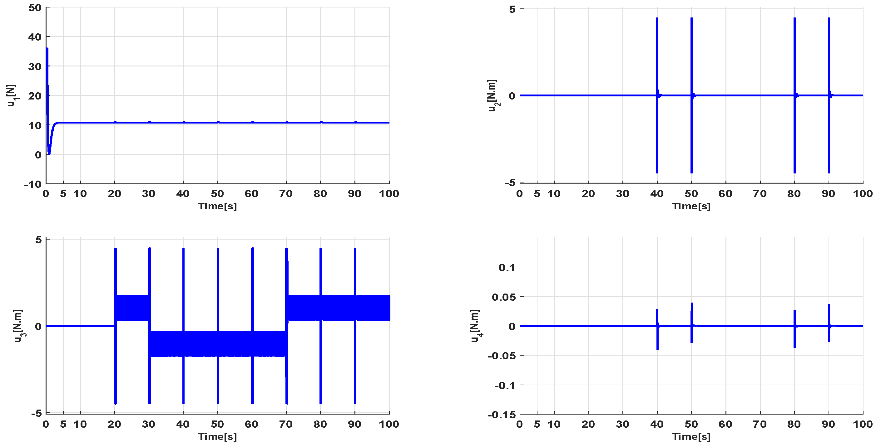
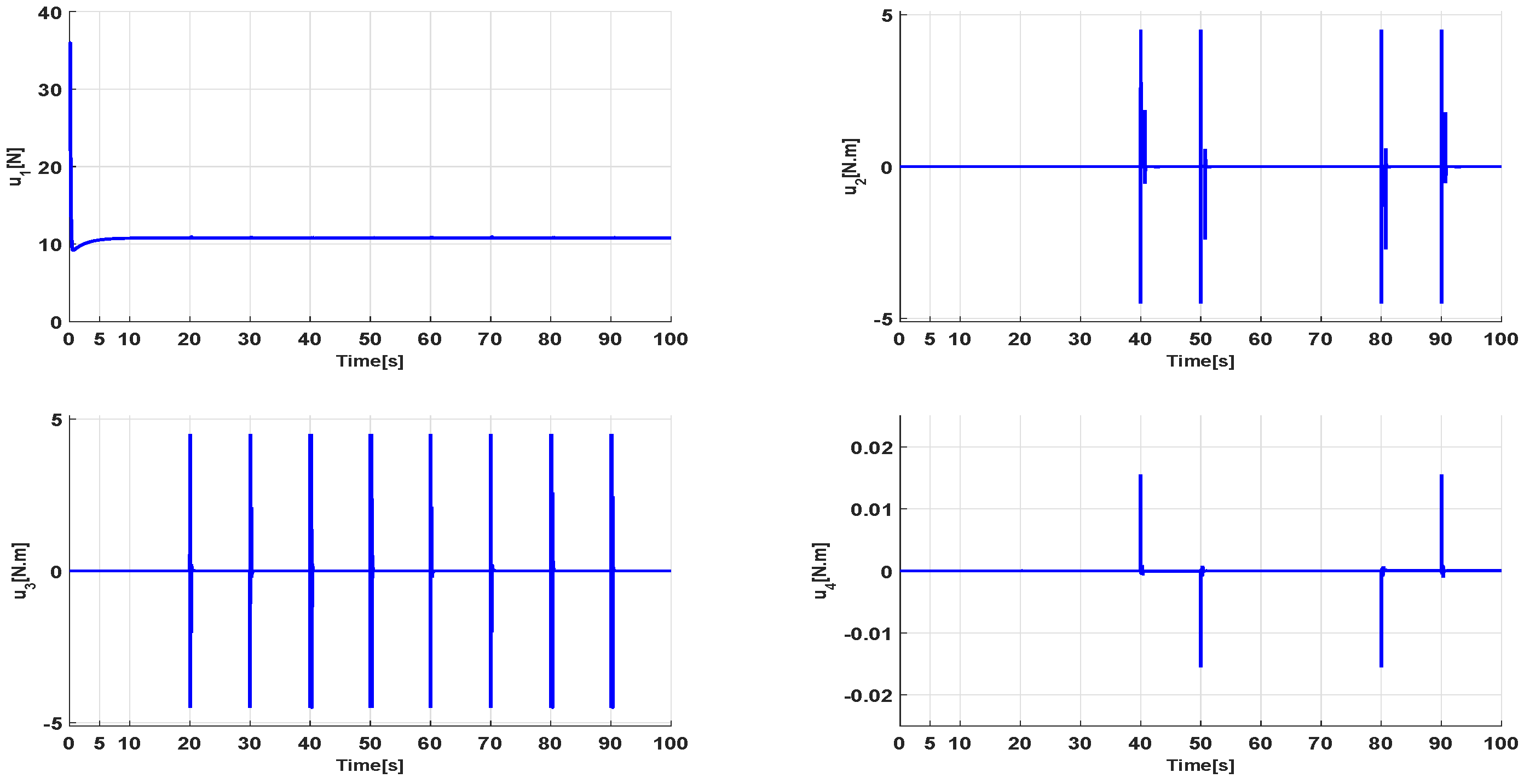
Figure 3 and
Figure 5 show control inputs, with the control signal
stabilizing around a constant that corresponds to the altitude
z and the sliding surface
. The changes in the two control signals
and
are determined by the dynamics of
and
and
in the square trajectory, and for the “
” configuration, it is more energetic compared to the “
” configuration, as well as very low values of
, resulting in low power consumption.
We remark that the “” configuration consumes less energy compared to the “” configuration. The proposed control technique ensures rapidity, accuracy and strong stability of the system, demonstrating that the quadrotor can track its desired trajectory in our scenario and for two configurations of our reconfigurable UAV. Furthermore, it is obvious that MIMO-SMC decreases the chattering phenomena, errors and energy consumption.
7. Comparative Study
First, let us define the energy consumed by the vehicle during the flight.
where
is the torque generated by motor
i, and
is the angular speeds of the propellers at time
t. We assess the consumed energy by the reconfigurable UAV in each configuration for a trajectory (square) under an optimal control approach (MIMO-SMC based on ACO) using Equation (
20), which is summarized in
Table 2.
We calculate the percentage difference between the consumed energy obtained with the classic “” configuration compared to the energy consumed with the configuration, which is , and between the configuration and , it is . The configuration consumes less energy compared to other special configurations (“”, “”, , “” and “”). This comparative study quantifies the amount of energy consumed by the reconfigurable UAV in each configuration. To optimize the energy consumed along a predefined trajectory, we change the configuration “”, “”, “”, “”, “” and “” of the reconfigurable drone during the flight to accomplish a well-defined mission, which will be the objective of future work.
8. Conclusions and Future Work
We are interested in reconfigurable UAVs in this work. When compared to conventional drones, there are several advantages, including the reduction in energy consumed during flight, handling and transporting of objects, execution of specific missions, and various configurations. These new drones are distinguished primarily by a transformable and complex mechanical structure, which makes modeling and control of the latter very difficult tasks. We were able to establish the use of a generic model in the literature in this manuscript. After that, we ordered the drone proposed by the Multiple Inputs and Multiple Outputs Sliding Mode Controller in order to stabilize it in flight while taking into account uncertain parameters caused by aerial transformation for our scenario and for each configuration. As well as the adequate gains of the control, we used the Ant Colony optimization technique. Finally, several simulations were run to demonstrate the efficiency of the proposed controller in terms of precision, speed, and stability, and we concluded which configuration consumed the least amount of energy.
We hope to confirm the results obtained in the future by applying the proposed controller to a real reconfigurable UAV, estimating disturbances, using genetic algorithms, and changing configurations during flight.
Author Contributions
Methodology, M.G.; software, K.B., M.G., Y.B., M.H.; validation, K.B., M.G., Y.B., M.H.; formal analysis, K.B., M.G., Y.B.; writing—original draft preparation, K.B.; writing—review and editing, K.B.; visualization, M.G.; funding acquisition, M.G., Y.B. All authors contributed equally to this work. All authors have read and agreed to the published version of the manuscript.
Funding
This research received no external funding.
Institutional Review Board Statement
Not applicable
Informed Consent Statement
All authors have read and agreed to publish this work.
Data Availability Statement
Not applicable
Conflicts of Interest
The authors declare that they have no conflict of interest.
References
- Falanga, D.; Kleber, K.; Mintchev, S.; Floreano, D.; Scaramuzza, D. The Foldable Drone: A Morphing Quadrotor That Can Squeeze and Fly. IEEE Robot. Autom. Lett. 2019, 4, 209–216. [Google Scholar] [CrossRef] [Green Version]
- Zhao, M.; Kawasaki, K.; Chen, X.; Noda, S.; Okada, K.; Inaba, M. Whole-body aerial manipulation by transformable multirotor with two-dimensional multilinks. In Proceedings of the 2017 IEEE International Conference on Robotics and Automation (ICRA), Singapore, 29 May–3 June 2017; pp. 5175–5182. [Google Scholar]
- Wallace, D.A. Dynamics and Control of a Quadrotor with Active Geometric Morphing. Master’s Thesis, University of Washington, Seattle, WA, USA, 2016. [Google Scholar]
- Zhao, M.; Anzai, T.; Shi, F.; Chen, X.; Okada, K.; Inaba, M. Design, modeling, and control of an aerial robot dragon: A dual-rotor-embedded multilink robot with the ability of multi-degree-of-freedom aerial transformation. IEEE Robot. Autom. Lett. 2018, 3, 1176–1183. [Google Scholar] [CrossRef]
- Bouabdallah, S.; Noth, A.; Siegwart, R. PID vs. LQ control techniques applied to an indoor micro quadrotor. In Proceedings of the 2004 IEEE/RSJ International Conference on Intelligent Robots and Systems (IROS)(IEEE Cat. No. 04CH37566), Sendai, Japan, 28 September–2 October 2004; Volume 3, pp. 2451–2456. [Google Scholar]
- Bressan, G.; Invernizzi, D.; Panza, S.; Lovera, L. Attitude control of multirotor uavs: Cascade p/pid vs pi-like architecture. In Proceedings of the 5th CEAS Specialist Conference on Guidance, Navigation and Control-EuroGNC, Milano, Italy, 3–5 April 2019; pp. 1–20. [Google Scholar]
- Atheer, L.S.; Haider, A.M.; Khalaf, S.G. Flight PID controller design for a UAV quadrotor. Sci. Res. Essays 2010, 5, 3660–3667. [Google Scholar]
- Bouabdallah, S. Design and Control of Quadrotors with Application to Autonomous Flying; Technical Report; Epfl: Lausanne, Switzerland, 2007. [Google Scholar]
- Reizenstein, A. Position and Trajectory Control of a Quadcopter Using PID and LQ Controllers. Master’s Thesis, Linköping University, Linköping, Sweden, 2017. [Google Scholar]
- Araar, O.; Aouf, N. Full linear control of a quadrotor UAV, LQ vs. H∞. In Proceedings of the 2014 UKACC International Conference on Control (CONTROL), Loughborough, UK, 9–11 July 2014; pp. 133–138. [Google Scholar]
- Choi, Y.; Ahn, H. Nonlinear control of quadrotor for point tracking: Actual implementation and experimental tests. IEEE/ASME Trans. Mechatronics 2014, 20, 1179–1192. [Google Scholar] [CrossRef]
- Mukherjee, P.; Waslander, S.L. Direct adaptive feedback linearization for quadrotor control. In Proceedings of the AIAA Guidance, Navigation, and Control Conference, Minneapolis, MN, USA, 3–16 August 2012; p. 4917. [Google Scholar]
- Voos, H. Nonlinear control of a quadrotor micro-UAV using feedback-linearization. In Proceedings of the 2009 IEEE International Conference on Mechatronics, Malaga, Spain, 14–17 April 2009; pp. 1–6. [Google Scholar]
- Deepak, G.; Cheolkeun, H. Control of a Quadrotor Using a Smart Self-Tuning Fuzzy PID Controller. Int. J. Adv. Robot. Syst. 2013, 10, 380. [Google Scholar]
- Huo, X.; Huo, M.; Karimi, H.R. Attitude stabilization control of a quadrotor UAV by using backstepping approach. Math. Probl. Eng. 2014, 2014, 749803. [Google Scholar] [CrossRef] [Green Version]
- Kobilarov, M. Trajectory control of a class of articulated aerial robots. In Proceedings of the 2013 International Conference on Unmanned Aircraft Systems (ICUAS), Atlanta, GA, USA, 28–31 May 2013; pp. 958–965. [Google Scholar]
- Utkin, V. Variable structure systems with sliding modes. IEEE Trans. Autom. Control 1977, 22, 212–222. [Google Scholar] [CrossRef]
- Slotine, J.; Li, W. Applied Nonlinear Control; Prentice Hall: Englewood Cliffs, NJ, USA, 1991; Volume 199. [Google Scholar]
- Muño, F.; González-Hernández, I.; Salazar, S.; Espinoza, E.S.; Lozano, R. Second order sliding mode controllers for altitude control of a quadrotor UAS: Real-time implementation in outdoor environments. Neurocomputing 2017, 233, 61–71. [Google Scholar] [CrossRef]
- Elfeky, M.; Elshafei, M.; Saif, A.W.A.; Al-Malki, M.F. Modeling and simulation of quadrotor UAV with tilting rotors. Int. J. Control. Autom. Syst. 2016, 14, 1047–1055. [Google Scholar] [CrossRef]
- Hintz, C.; Torno, C.; Carrillo, L.R.G. Design and dynamic modeling of a rotary wing aircraft with morphing capabilities. In Proceedings of the 2014 International Conference on Unmanned Aircraft Systems (ICUAS), Orlando, FL, USA, 27–30 May 2014; pp. 492–498. [Google Scholar]
- Riviere, V.; Manecy, A.; Viollet, S. Agile robotic fliers: A morphing-based approach. Soft Robot. 2018, 5, 541–553. [Google Scholar] [CrossRef] [PubMed]
- Nemati, A.; Kumar, M. Non-linear control of tilting-quadcopter using feedback linearization based motion control. In Proceedings of the Dynamic Systems and Control Conference, San Antonio, TX, USA, 22–24 October 2014; American Society of Mechanical Engineers: New York, NY, USA, 2014; Volume 46209, p. V003T48A005. [Google Scholar]
- Derrouaoui, S.H.; Bouzid, Y.; Guiatni, M. PSO Based Optimal Gain Scheduling Backstepping Flight Controller Design for a Transformable Quadrotor. J. Intell. Robot. Syst. 2021, 102, 1–25. [Google Scholar] [CrossRef]
- Derrouaoui, S.H.; Bouzid, Y.; Guiatni, M. Towards a new design with generic modeling and adaptive control of a transformable quadrotor. Aeronaut. J. 2021, 125, 2169–2199. [Google Scholar] [CrossRef]
- Lu, X.Y.; Spurgeon, S.K. Asymptotic stabilisation of multiple input nonlinear systems via sliding modes. Dyn. Control 1998, 8, 231–254. [Google Scholar] [CrossRef]
- Colorni, A.; Dorigo, M.; Maniezzo, V. Distributed optimization by ant colonies. In Proceedings of the 1st European Conference on Artificial Life, Paris, France, 11–13 December 1991; pp. 134–142. [Google Scholar]
- Dorigo, M. Optimization Learning and Natural Algorithms. Ph.D. Thesis, Politecnico di Milano, Milan, Italy, 1992. [Google Scholar]
| Disclaimer/Publisher’s Note: The statements, opinions and data contained in all publications are solely those of the individual author(s) and contributor(s) and not of MDPI and/or the editor(s). MDPI and/or the editor(s) disclaim responsibility for any injury to people or property resulting from any ideas, methods, instructions or products referred to in the content. |
© 2023 by the authors. Licensee MDPI, Basel, Switzerland. This article is an open access article distributed under the terms and conditions of the Creative Commons Attribution (CC BY) license (https://creativecommons.org/licenses/by/4.0/).


