1. Introduction
The first part of this paper includes simplified information about the growth and increase in the number of electric buses EBs in the world, in addition to the definition and structure of in-wheel electric motors (IWMs). In addition, in this part, the importance of the active suspension system is mentioned, as well as the control method used, which is the LQR control.
Clean public transportation systems are becoming increasingly important in today’s cities to combat air pollution. In most of the world’s countries, energy and environmental policies have increased recommendations and incentives to introduce a large amount of clean technology for vehicles, including electric buses, by 2030 [
1]. In recent years, there has been a significant increase in the use of electric buses around the world, particularly in China.
Electric vehicles have contributed to a more than 3% reduction in the growth of oil use. Moreover, electric buses account for around 3/4 of the reduction in this consumption. As evidence of this, a significant portion of our energy transformation will require the widespread adoption of electrified public transportation.
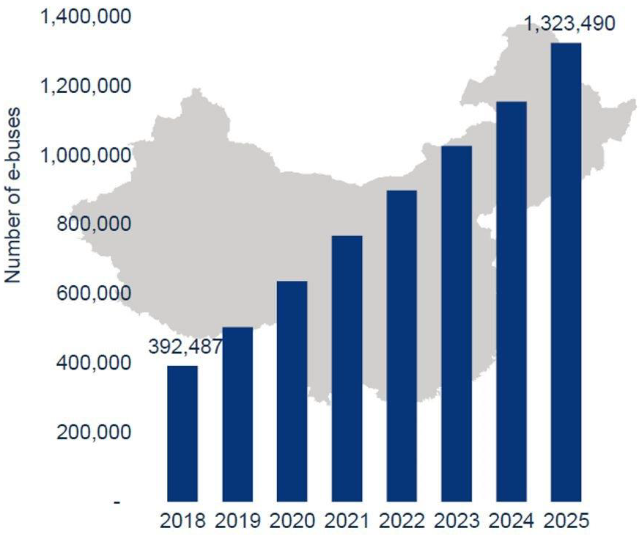
In 2018, Bloomberg New Energy Finance, one of the key research providers, produced a report titled “Electric Buses in Cities: Driving towards Cleaner Air and Lower CO
2”, which forecasted a tripling of the number of electric buses by 2025, as illustrated in
Figure 1. That is 1.2 million buses, or roughly half of all buses currently in service, that would be converted to electric buses [
2].
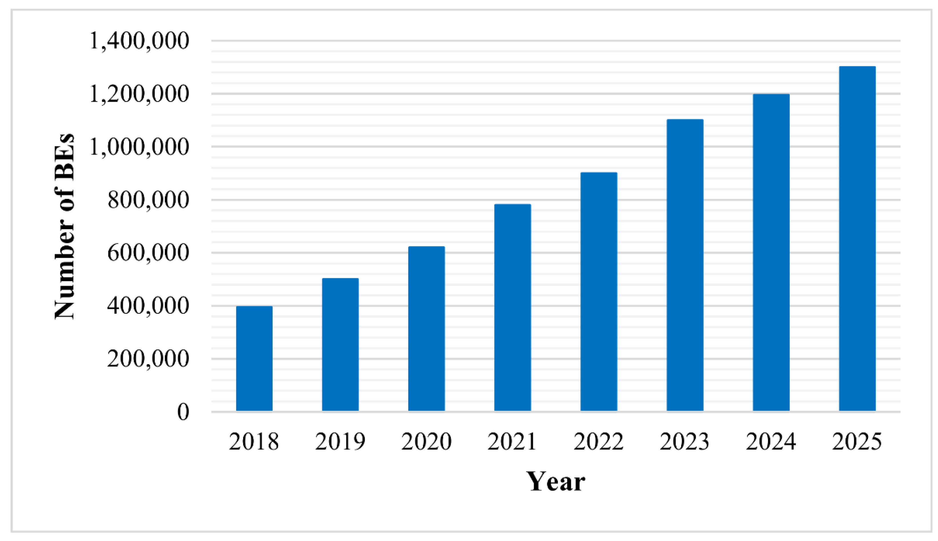
According to Wood Mackenzie Power and Renewables, adoption of electric buses in China will expand dramatically from 2018 to 2025 [
3], as illustrated in
Figure 2.
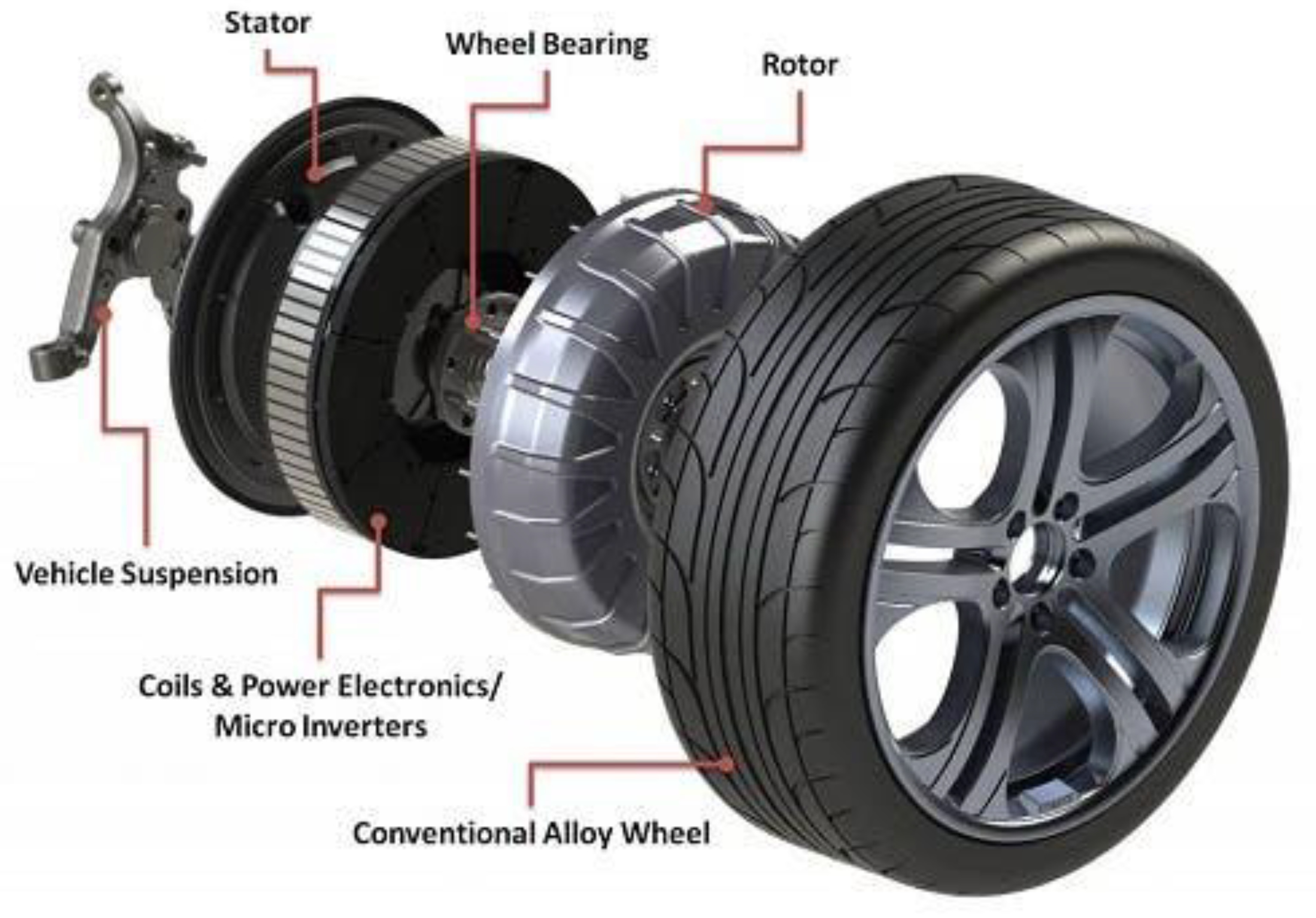
One sort of electric vehicle drive system is the in-wheel motor that is shown in
Figure 3. In conventional electric vehicles, the gasoline engine is replaced by an electric motor; this motor incorporates motors directly into each of the driving wheels.
Electric motors are used in the wheels of electric vehicles, and they are called in-wheel electric motors (IWMs), where these motors increase the weight of the wheels clearly, and this increase in weight affects the performance of the suspension system in electric buses.
Suspension is a crucial aspect of a vehicle’s design because its purpose is to provide comfort while driving in a variety of road and weather situations. Suspension analyses were carried out in a study in order to analyze a vehicle’s performance with an increased mass on each wheel [
4].
Numerous control techniques have been offered to address these suspension issues. Ride comfort is improved by reducing the body acceleration induced by the car’s body when it encounters road disturbances from both smooth and real road roughness, which is accomplished using a fuzzy control algorithm [
5,
6]. Numerous active suspension control techniques, including linear quadratic Gaussian control, adaptive control, and nonlinear control, have been developed and proposed to address these issues [
7,
8,
9]. In this work, the LQR method was chosen to evaluate the active suspension system of an electric bus.
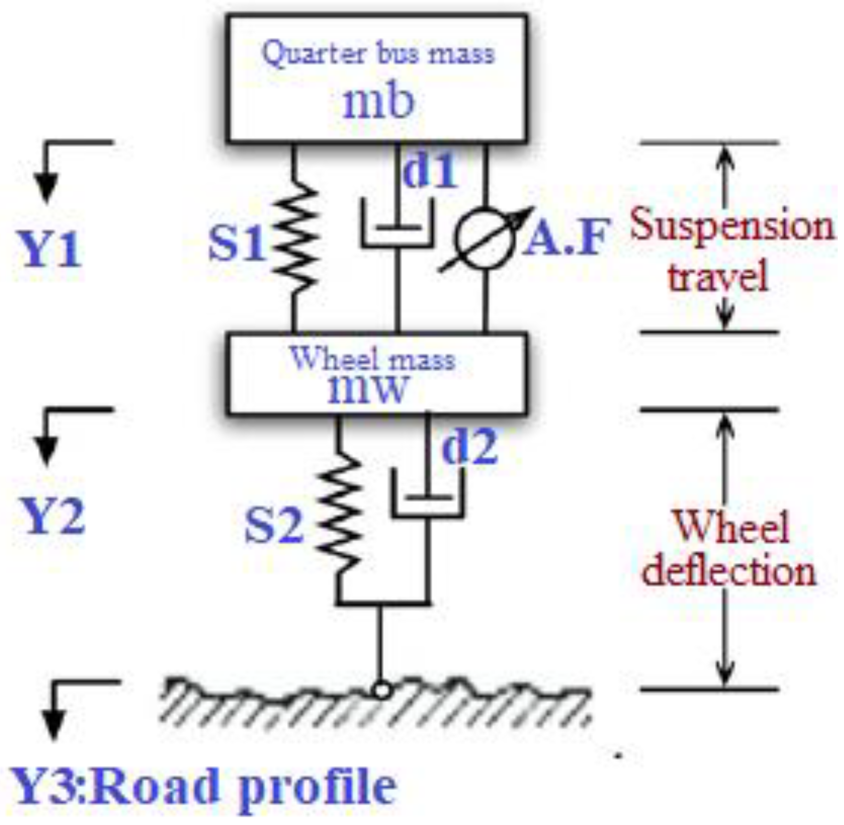
2. Bus Suspension System Model
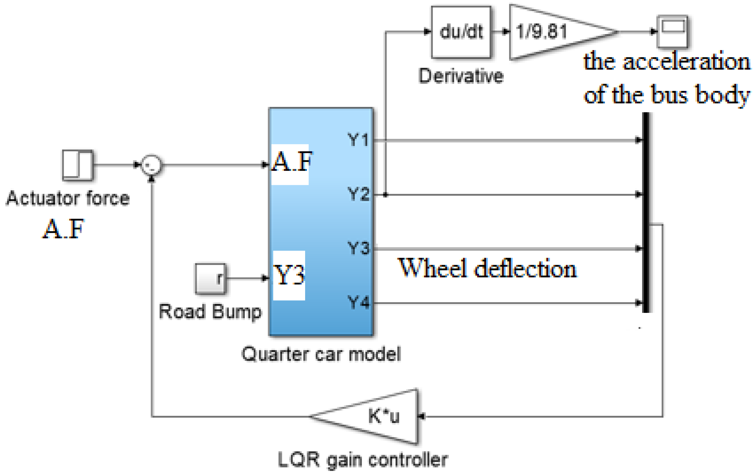
The control problem of designing any vehicle suspension system is both exciting and demanding. When designing a suspension system, a quarter model (one of the four vehicle wheels) is employed to reduce the problem to a single-dimensional multiple spring–damper system. The following figure is a diagram of this system. This model is for an active suspension system that includes an actuator capable of generating the actuating force (A.F) required to control the bus body’s motion and the wheel deflection.
A description and the values of the variables of the active suspension system of the electric bus are shown in both
Table 1 and
Figure 4.
According to the system depicted in
Figure 4, the system parameters stated in
Table 1, and Newton’s law, we can formulate the system’s dynamic equations as follows:
where:
A.F: the actuator force
Y3: the road surface profile
Y1−Y2: represents the suspension travel
: denotes the velocity of the bus body or the sprung mass
: symbolizes the acceleration of the bus body
Y2−Y3: denotes the wheel deflection
Y2: symbolizes the vertical velocity of the wheel
The two main parameters that are taken into account when designing suspension systems are the acceleration of the bus body, which is symbolized by “” and the second parameter is the deflection of the wheel, symbolized by “Y2−Y3”, where the first symbol indicates passenger comfort while the second symbol indicates road holding.
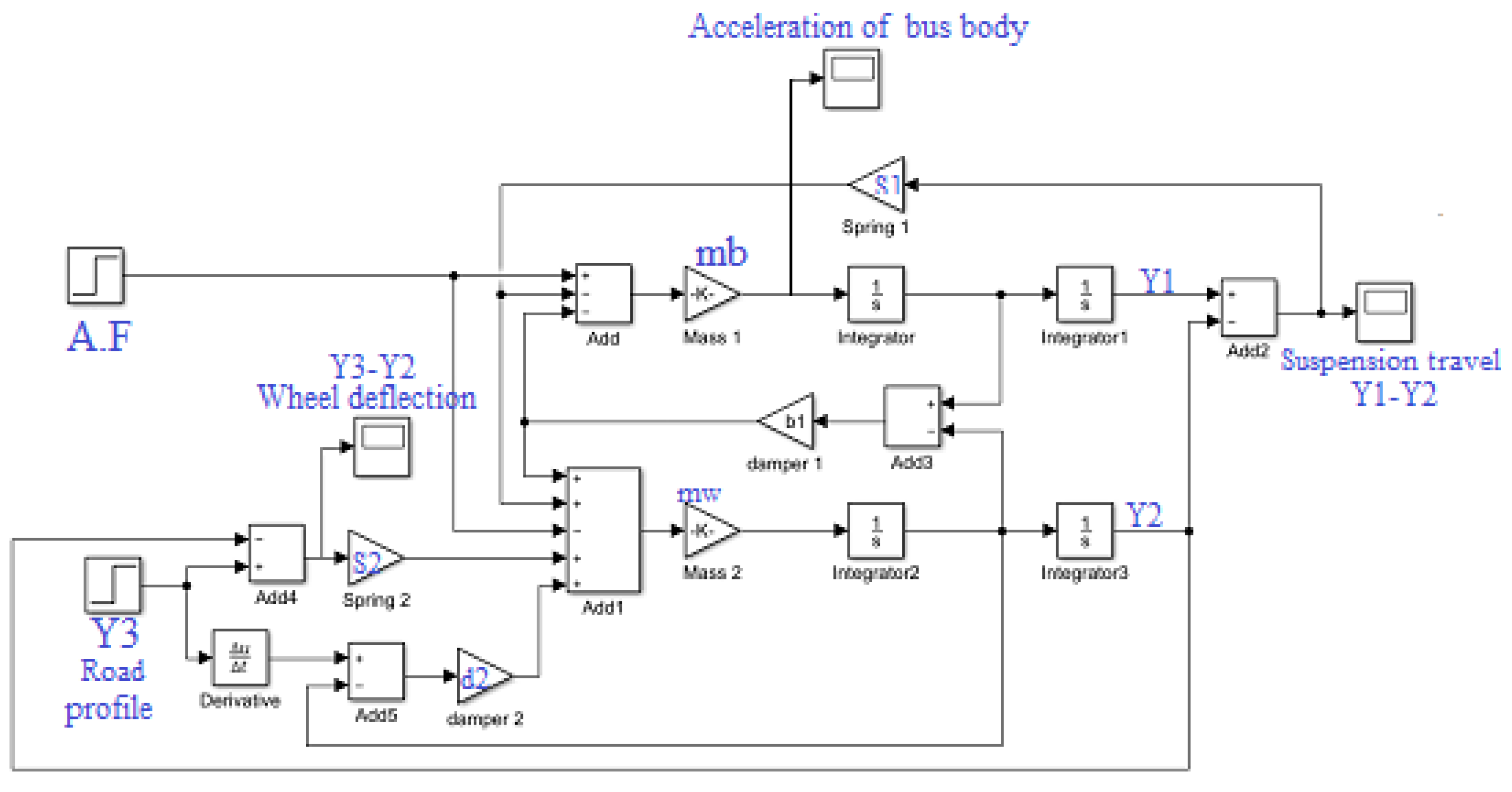
According to all the previous data represented by the system diagram in addition to the two dynamic equations, it is possible to create a Simulink model for the bus as follows (
Figure 5):
3. Control Process
There are many studies related to the design and evaluation of the performance of suspension systems in vehicles, but the impact of the weight of in-wheel electric motors on the performance of the system has not been addressed in most of the published works. In this paper, one of the well-known control methods, linear quadratic control (LQR), will be used.
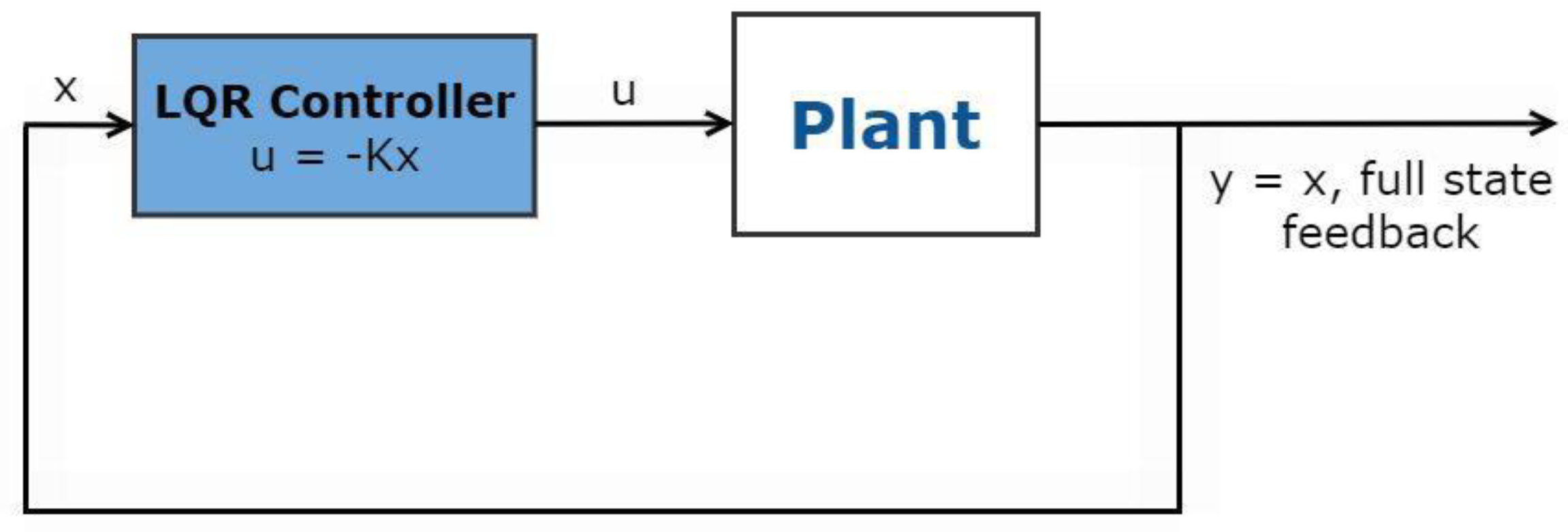
The linear quadratic regulator (LQR) is an optimum control that can be used for single-input single-output (SISO) or multi-input multi-output (MIMO) systems. It not only provides good stability but also has the potential to guarantee the system’s stability margin [
10]. It is worth noting that LQR can provide more optimal energy usage than PID and fuzzy controllers [
11]. The linear quadratic regulator (LQR) is an ideal full-state feedback control law that regulates the control system by minimizing a quadratic cost function.
Figure 10 illustrates the linear quadratic regulator controller schematic. As seen in
Figure 11, we can see the block design of a full-state feedback controller utilizing LQR.
4. Simulations and Discussion
Through the suspension system shown in
Figure 4, which represents a suspension system for a quarter of an electric bus, it consists of two main blocks, which are a quarter of the bus’s mass, and the second block is the wheel mass, which is referred to by another term as the unsprung mass. The system also contains a set of springs and dampers as shown in the same figure. Using Newton’s second law of motion, the two equations of motion were written for the system; based on the two equations, the Simulink model shown in
Figure 5 was created. The inputs to the system are the actuator force and the road profile, and the main important outputs of the system are the acceleration of the bus’s body and deflection of the wheel, as they refer to the passenger’s comfort and road holding, respectively.
One of the well-known control methods was used, which has been explained in this paper, and it is the linear quadratic regulator, which was used on the basis of which control system was implemented, as shown in
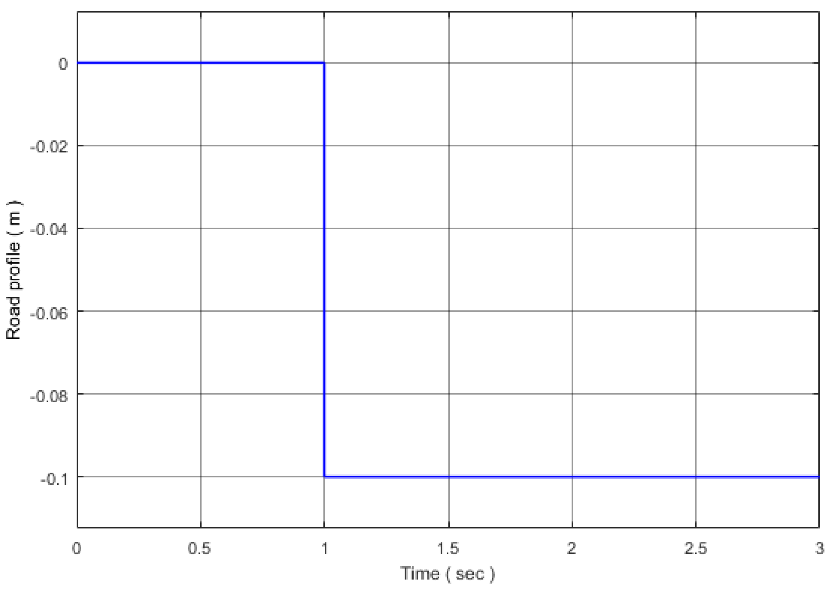
Figure 11. In this study, the behavior of the system was studied based on several variables, including the mass of the wheel (this was a standard wheel and an in-wheel motor) and the road profile (this was a step input and a bumpy road input).
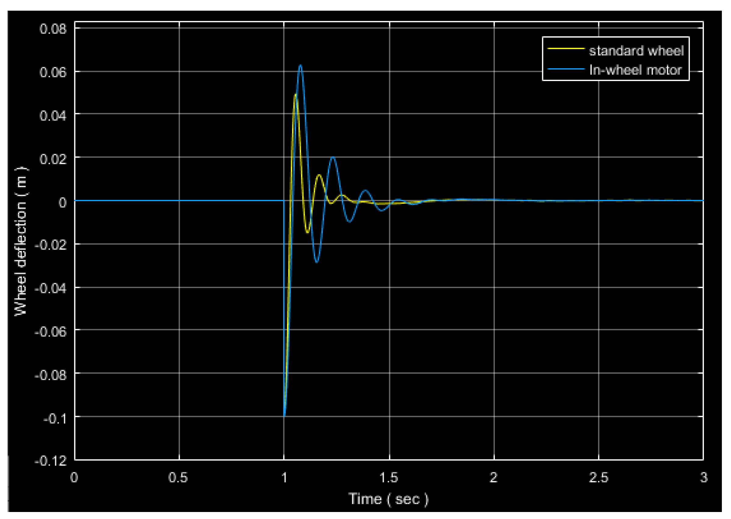
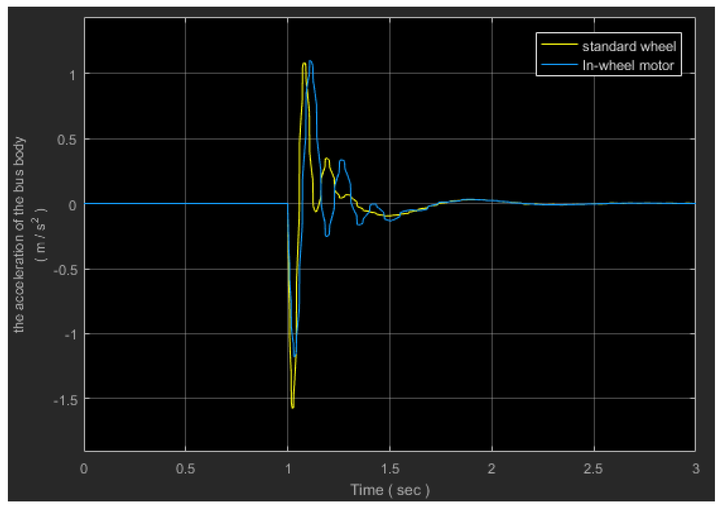
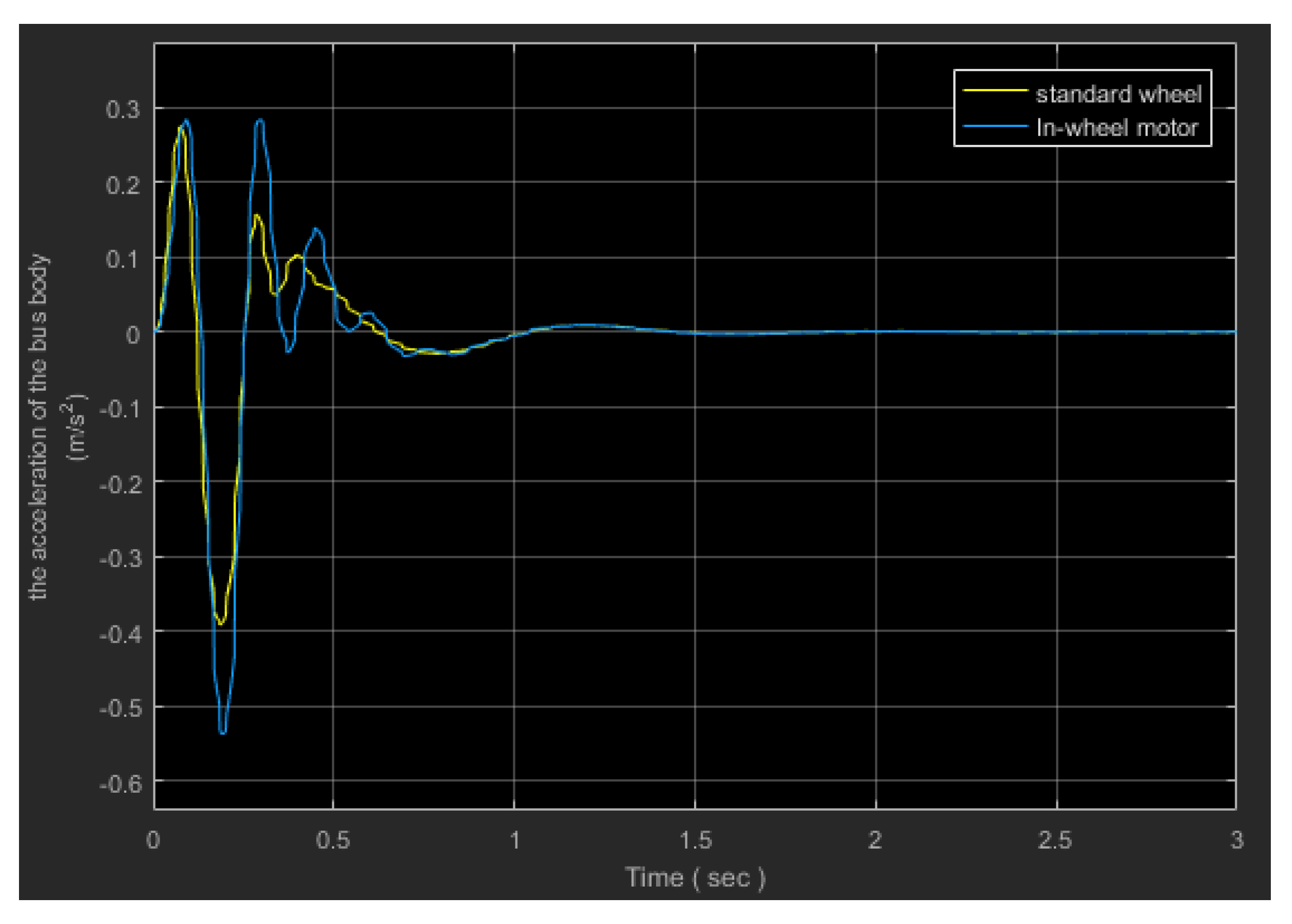
Figure 12 and
Figure 13 denotes two parameters that affect the system’s performance which are the wheel deflection and the acceleration of sprung mass with the step input, while
Figure 14 and
Figure 15 show the same parameters but with the bumpy road input. The yellow lines in the four figures indicate the state of the system when using the standard wheels, while the blue lines indicate the system’s performance when electric motors are used. We conclude that the use of in-wheel electric motors had a negative impact to some extent, and this is because these motors increase the weight of the wheels.
5. Conclusions
The usage of an LQR controller to regulate the active suspension of an electric quarter bus is demonstrated in this study, as similar models are utilized in a large number of universities and institutions worldwide. It is critical that we are able to execute modeling in such a way that we may utilize a variety of different parameters and still obtain identical results. The main parameter that was taken into account was the weight of the bus’s wheel, as it differs in this system. Once a standard wheel was used, a wheel with an electric motor was used again. This paper has shown that the electric motor increased the weight of the wheel, which negatively affected the performance of the system, so we need to use other control methods so that we may obtain better performance for the electric bus suspension system.
Author Contributions
Conceptualization, M.B. and A.A.A.; methodology M.B., A.A.A., M.M.K., A.A., M.M.R. and A.S.D.A.; formal analysis, A.A.A. and M.M.K.; investigation, M.B. and A.A.A. and A.A.; resources, all authors; data curation, all authors; writing—original draft preparation, M.B. and A.A.A.; writing—review and editing, all authors; visualization, all authors; supervision, all authors; project administration, A.A.A. All authors have read and agreed to the published version of the manuscript.
Funding
This research received no external funding.
Institutional Review Board Statement
Not applicable.
Informed Consent Statement
Not applicable.
Data Availability Statement
Not available.
Conflicts of Interest
The authors declare no conflict of interest.
References
- Houbbadi, A.; Pelissier, S.; Trigui, R.; Redondo-Iglesias, E.; Bouton, T. Overview of Electric Buses deployment and its challenges related to the charging—The case study of TRANSDEV. In Proceedings of the 32nd Electric Vehicle Symposium (EVS32), Lyon, France, 19–22 May 2019. [Google Scholar]
- Electric Buses: Where Are We? Available online: https://www.ies-synergy.com/en/electric-buses-where-are-we/ (accessed on 15 March 2021).
- Global Electric Bus Adoption. Global Electric Bus Adoption to Triple by 2025. 2019. Available online: https://www.greentechmedia.com/articles/read/global-electric-bus-adoption-is-set-to-triple-by-2025 (accessed on 6 August 2021).
- Kulkarni, A.; Ranjha1, S.A.; Kapoor, A. A quarter-car suspension model for dynamic evaluations of an in-wheel electric vehicle. Proc. Inst. Mech. Eng. Part D J. Automob. Eng. 2018, 232, 1139–1148. [Google Scholar] [CrossRef]
- Salem, M.M.M.; Ayman, A.A. Fuzzy Control of a Quarter Car Suspension System. World Acad. Sci. Eng. Technol. 2009, 53, 1276–1281. [Google Scholar]
- Ahmed, A.A.; Jomah, O.S.M. Modeling and Control of Car Active Suspension System Using a Neural Network-based Controller and Linear Quadratic Regulator Controller. In Proceedings of the 2020 IEEE 2nd International Conference on Electronics, Control, Optimization and Computer Science (ICECOCS), Kenitra, Morocco, 2–3 December 2020; pp. 1–6. [Google Scholar] [CrossRef]
- Gordon, T.J.; Marsh, C.; Milsted, M.G. A Comparison of Adaptive LQG and Nonlinear Controllers for Vehicle Suspension Systems, Vehicle System. Dynamics 1991, 20, 321–340. [Google Scholar]
- Ben Gaid, M.; Cela, A.; Kocik, R. Distributed control of a car suspension system. In Proceedings of the 5th EUROSIM Congress on Modeling and Simulation, Noisy-le-Grand, Franca, 6–10 September 2004. [Google Scholar]
- Ahmed, A.A.; Emheisen, M. Analysis of Vehicle Handling Using a Simple Track Model of Automobile. In Proceedings of the 2019 19th International Conference on Sciences and Techniques of Automatic Control and Computer Engineering (STA), Sousse, Tunisia, 24–26 March 2019; pp. 130–133. [Google Scholar] [CrossRef]
- Priyatmadi, A.P.; Sandiwan, H.; Wijaya, A.C. Application of spsa LQR tuning on quadrotor. In Proceedings of the 6th International Annual Engineering Seminar (IAES), Yogyakarta, Indonesia, 12–14 August 2016. [Google Scholar]
- Maghfiroh, H.; Ataka, A.; Wahyunggoro, O.; Cahyadi, A.I. Optimal energy control of dc motor speed control: Comparative study. In Proceedings of the International Conference on Computer, Control, Informatics and Its Applications, Jakaarta, Indonesia, 19–20 November 2013. [Google Scholar]
| Disclaimer/Publisher’s Note: The statements, opinions and data contained in all publications are solely those of the individual author(s) and contributor(s) and not of MDPI and/or the editor(s). MDPI and/or the editor(s) disclaim responsibility for any injury to people or property resulting from any ideas, methods, instructions or products referred to in the content. |
© 2023 by the authors. Licensee MDPI, Basel, Switzerland. This article is an open access article distributed under the terms and conditions of the Creative Commons Attribution (CC BY) license (https://creativecommons.org/licenses/by/4.0/).


 ,
, 


