Proceeding Paper

Observer Backstepping Design for Flight Control †

by
Ben Messaoud Safinaz
*,
Belkheiri Mohammed
and
Belkheiri Ahmed
Laboratory of Telecommunications, Signals and Systems, University Amar Telidji of Laghouat, P.O. Box 37G, Guardaia Road, Laghouat 03000, Algeria
*
Author to whom correspondence should be addressed.
Presented at the 2nd International Conference on Computational Engineering and Intelligent Systems, Online, 18–20 November 2022.
Eng. Proc. 2023, 29(1), 3; https://doi.org/10.3390/engproc2023029003
Published: 10 January 2023

Abstract

:
This paper presents observer backstepping as a new nonlinear flight control design framework. Flight control laws for general-purpose maneuvering in the presence of nonlinear lift and side forces are designed. The controlled variables are the angle of attack, the sideslip angle, and the roll rate. The stability has been proved using Lyapunov stability criteria. Control laws were evaluated using realistic aircraft simulation models, with highly encouraging results.

1. Introduction

Several novel design approaches for controlling nonlinear dynamic systems have been developed in recent years. Backstepping is one of these techniques. Backstepping allows for the methodical design of stabilizing control laws in certain classes of nonlinear systems. A backstepping design can be used in systems with limited model information. In this scenario, the aim is to choose a control law that decreases the Lyapunov function for all systems with the given model uncertainty. As a result of its simultaneous and often implicit appearance in several papers in the late 1980s, the origin of backstepping is not quite clear. The work of Professor Petar V. Kokotovi´c and his coworkers has, however, brought backstepping to the forefront to a significant extent. The 1991 Bode lecture at the IEEE CDC, held by Kokotovi´c [1], was devoted to the evolving subject and in 1992, Kanellakopoulos et al. [2] presented a mathematical “toolkit” for designing control laws for various nonlinear systems using backstepping, where backstepping has to be performed under state observation. Backstepping designs are available for a wide range of electrical motors [3,4,5,6]. Wind turbines are considered in [7], ref [8] using backstepping while observer backstepping is the subject of [9]. In [10,11], backstepping is used for automatic ship positioning. Robotics is another field where backstepping designs can be found. Tracking control is considered in [12] and [13]. Backstepping control augmented by neural networks is proposed to address the tracking problem for robot manipulators [14] and for an induction machine based on a modified (FOC) method [15]. There are also a few papers that combine flight control and backstepping [16,17]. Ref. [18] treats formation flight control of unmanned aerial vehicles. Refs. [19,20] use backstepping to design flight control laws which are adaptive to changes in the aerodynamic forces and moments due to, e.g., actuator failures.
The reviewed literature reveals a key common feature, which is complete knowledge of the system states. In cases where not all the state variables can be measured, the need for observers arises. In general, the separation principle valid for linear systems does not hold for nonlinear systems in general. Therefore, care must be taken when designing the feedback law based on the state estimates. This is the topic of observer backstepping [2,21]. Comparatively, with the advances in nonlinear control theory, there is a desire in aircraft technology to achieve supermaneuverability for fighter aircraft. Using high angles of attack can lead to tactical advantages, as Herbst [22] and Well et al. [23] demonstrate when evaluating aircraft reversal maneuvers. The target is for the aircraft to return to its original position of departure with the same speed and altitude but on the opposite heading in the shortest time possible. By applying high angles of attack during the turn, the aircraft can maneuver in less airspace and complete the maneuver in less time. Flight dynamics are not linear in these maneuvers. Due to this change, linear control design tools are no longer useful for flight control design. In this paper, we investigate how backstepping can be used for flight control design to achieve stability over the entire flight envelope. Control laws based on the state estimates for general-purpose maneuvering are derived and their properties are investigated.
The paper is organized in the following manner: Section 2 presents the dynamic model of the aircraft. Section 3 describes the controller design methodology, which presents a backstepping observer design. Section 4 illustrates the simulation results and discussion of the proposed controller. The control strategy was applied using a realistic aircraft simulation model. Finally, conclusions are given in Section 5.

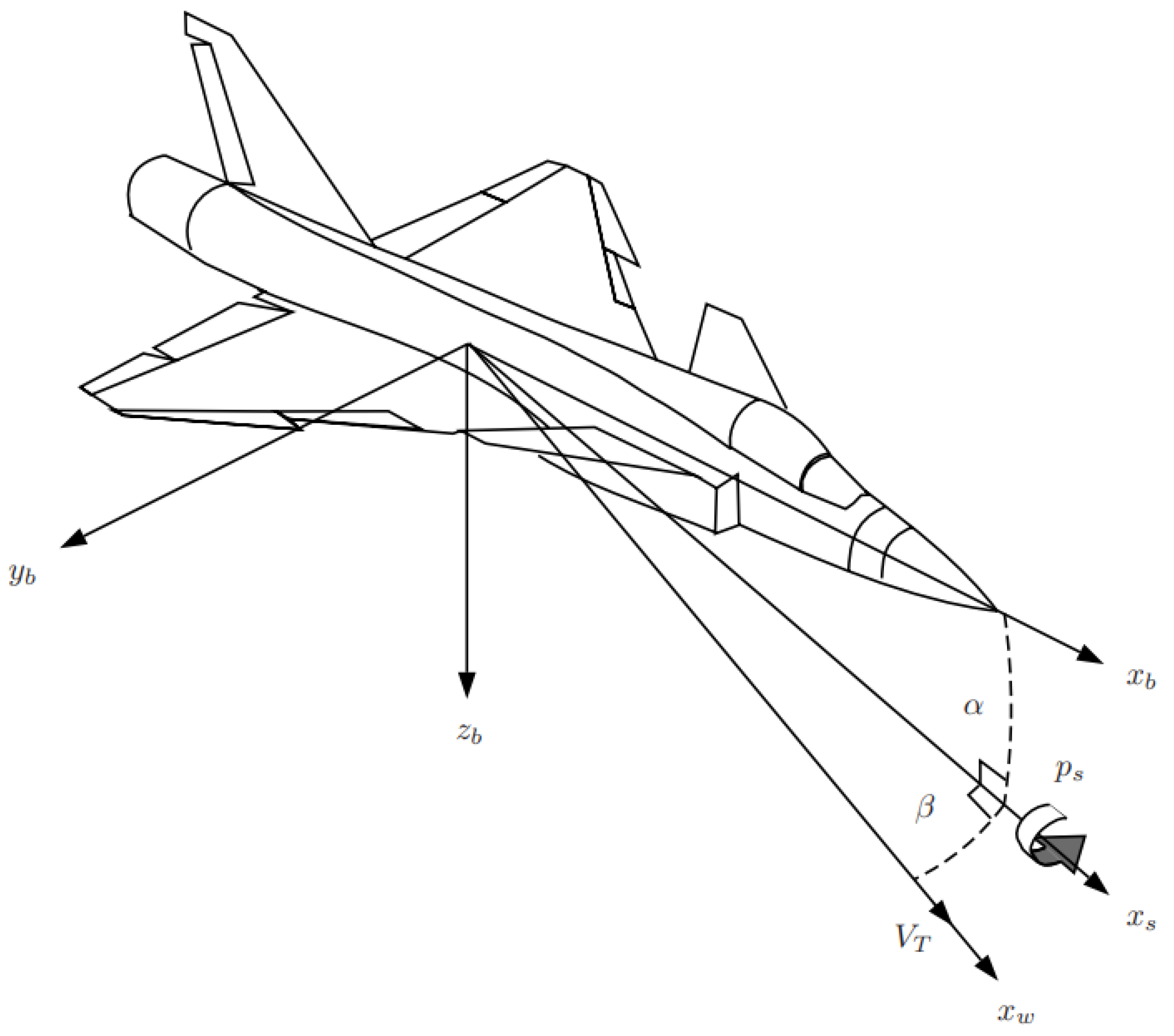
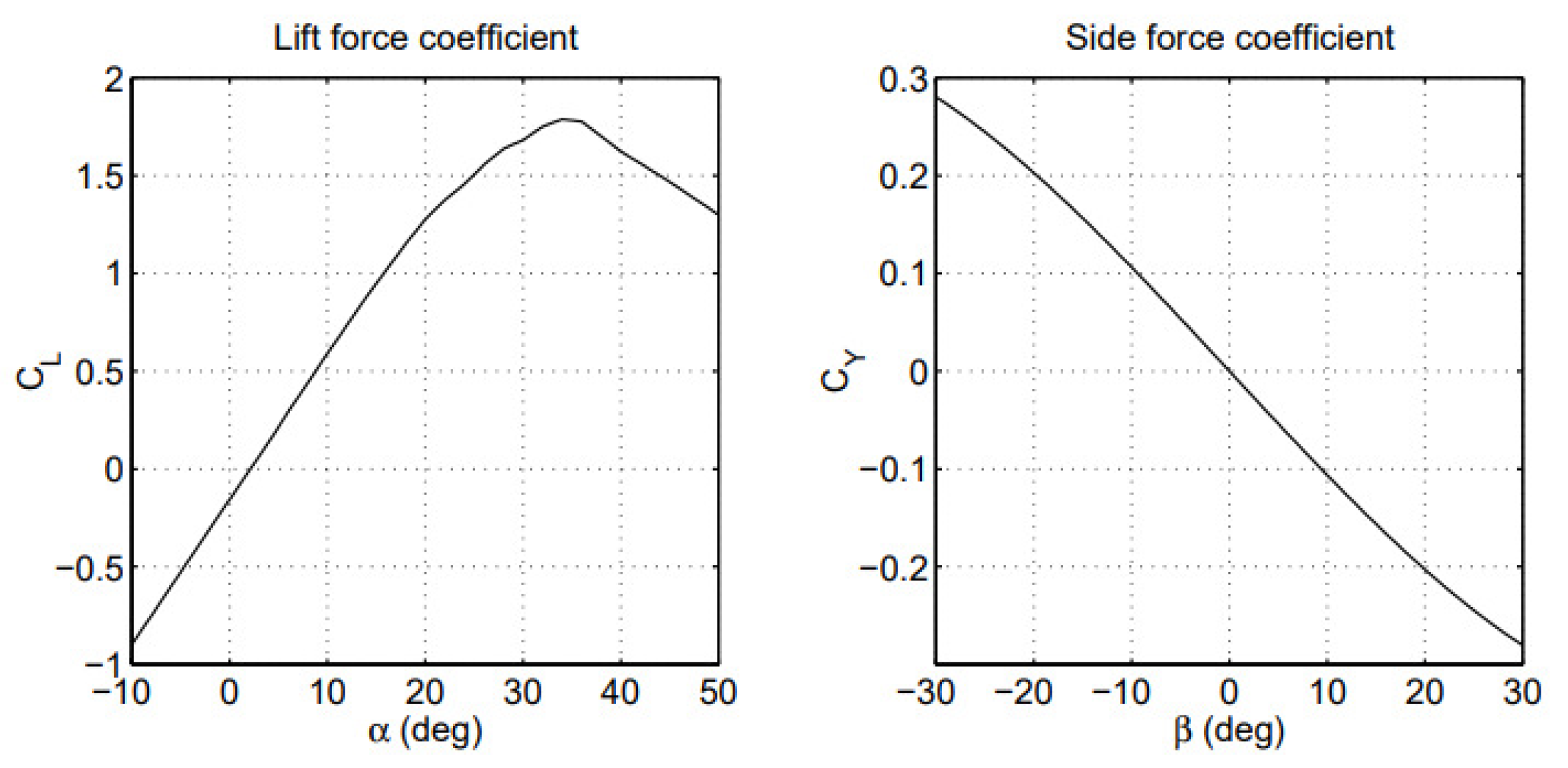
2. Aircraft Dynamics

Figure 1 illustrates the controlled variables, which are the angle of attack, sideslip angle, and roll rate about the stability x-axis.
The equations linking the variables to be controlled to control inputs are presented in Stevens and Lewis [24] and Boiffier’s [25] books. Who focuses on developing a model for control design, which consists of first-order differential equations.
α ˙ = q ( p cos α + r sin α ) tan β + 1 m V T cos β ( L F T sin α + m g 1 )
β ˙ = p sin α r cos α + 1 m V T ( Y F T cos α sin β + m g 2 )
m is the aircraft mass, F T is the engine thrust force and V T is the total velocity. L and Y are the lift and side forces respectively.
Figure 2 shows the typical lift force and side force coefficients used for the simulations later.
The force contributions due to gravity depend on the orientation of the aircraft, given by the pitch angle, θ , and the roll angle, ϕ , are
g 1 = g ( cos α cos θ cos ϕ + sin α sin θ )
g 2 = g ( cos β cos θ sin ϕ + sin β cos α sin θ sin α sin β cos θ cos ϕ )
Since the roll rate to be controlled, p s , is expressed in the stability-axes coordinate system, we need to establish the relationship between the body-axes angular velocity
ω = p q r T
To the stability-axes angular velocity,
ω s = p s q s r s T
through the transformation
ω s = R s b ω
where
R s b = cos α 0 sin α 0 1 0 sin α 0 cos α
In the control design, it is more convenient to work with ω s rather than ω . Introducing
u = u 1 u 2 u 3 T = ω ˙ s
Then we can rewrite the aircraft dynamics (1)–(2) as
p ˙ s = u 1
α ˙ = q s + f α
q ˙ s = u 2
β ˙ = r s + f β
r ˙ s = u 3
With
f α = p s t a n β + 1 m V T c o s β ( L ( α ) F T s i n α + m g 2 ) f β = 1 m V T ( Y ( β ) F T c o s α s i n β + m g 3 )
The lift and side force coefficient, C L and C Y , mainly depend on α and β respectively [26], this yields
L ( α ) = q ¯ S C L ( α ) Y ( β ) = q ¯ S C Y ( β )
where q ¯ = 1 2 ρ ( h ) V T 2 is the aerodynamic pressure, ρ is the air density, and S is the wing plan form area.

3. Observer Backstepping Design for Flight Control

3.1. Control Objective

Controlling maneuverability is the main objective in a dogfight. In order to control maneuverability, you must include relevant controlled variables in the lateral and longitudinal directions. Assuming that the latter directions are not applied simultaneously. We only deal with lateral commands in this paper, therefore the control objective is for the angle of attack α and the stability axis roll rate p s to follow α r e f and p s r e f , respectively. With the standard assumption being that a roll is performed with a steady angle of attack and no sideslip β . The sideslip must be kept at zero at all times in order for the aircraft to fly in a straight line. Furthermore, the aircraft velocity, V T and Euler angles, ϕ , θ , and ψ are considered constant.
The observer backstepping approach used in flight control laws based on the state estimates for general-purpose maneuvering does not cancel out the nonlinear parts of lift and side forces, L ( α ) and Y ( β ) , respectively.

3.2. Control Design

As a starting point, note that the dynamics of the angle of attack (6)–(7) are structurally similar to the sideslip dynamics (8)–(9). The two second-order systems can be expressed as
η ˙ 1 = f ( η 1 ) + η 2 η ˙ 2 = u
where η = η 1 η 2 T = α q s T Then we can rewrite (10) as
η ˙ = A η + σ f ( y ) + B u y = C η
where
A = 0 1 0 0 , B = 0 1 , C = 1 0 , σ = 1 0
A measurement can be made only with y. The following observer can be used to estimate the state of this class of nonlinear systems, characterized by geometric conditions in [[27], Theorem 5.1].
η ^ ˙ = A η ^ + K 0 ( η ^ 1 y ) + σ f ( y ) + B u
The error system is
η ˜ ˙ = A 0 η ˜ , η ˜ = η η ^
K 0 is chosen so that A 0 = A K 0 C in (13) is Hurwitz.
We only specify one subsystem, α d y n a m i c s (1), and the other subsystem, β d y n a m i c s (2) should be identical to the latter specified, for the derivation of observer backstepping.
S t e p 1 : We define the output error z 1 = η 1 η 1 r e f = η 1 λ 0 ( η 1 r e f ) and consider the second-order system
z ˙ 1 = η 2 + f ( η 1 ) η ˙ 1 r e f η 2 + μ 1 ( η 1 , η 1 r e f , η ˙ 1 r e f )
η ˙ 2 = u 2
Similarly to Lemma OIB [2], the following system is composed by replacing (15) with the second equation of the observer (12). With η ˜ 2 = η 2 η ^ 2
z ˙ 1 = η ^ 2 + μ 1 ( η 1 , η 1 r e f , η ˙ 1 r e f ) + η ˜ 2
η ^ ˙ 2 = u 2 + K 02 ( η ^ 1 η )
In the spirit of backstepping, we start by regarding η ^ 2 as the control input of (16)–(17), then Lemma NDM [2] would result in
η ^ 2 d e s = μ 1 ( η 1 , η 1 r e f , η ˙ 1 r e f ) c α z 1 λ 1 ( η 1 , η 1 r e f , η ˙ 1 r e f )
and
V 1 ( z 1 , η ˜ ) = 1 2 z 1 2 + η ˜ T P 0 η ˜
where
P 0 A 0 + A 0 T P 0 = I
S t e p 2 : Defining the state error z 2 = η ^ 2 λ 1 ( η 1 , η 1 r e f , η ˙ 1 r e f ) and (16)–(17) is rewritten as
z ˙ 1 = z 2 c α z 1 + η ˜ 2
z ˙ 2 = u 2 + K 02 ( η ^ 1 η ) λ 1 η 1 η 1 ˙ λ 1 η 1 r e f η ˙ 1 r e f λ 1 η ˙ 1 r e f η ¨ 1 r e f u 2 + μ 2 ( η 1 , η ^ 1 , η ^ 2 , η 1 r e f , η ˙ 1 r e f , η ¨ 1 r e f ) λ 1 η 1 η 2 ˜
We select the control law based on Lemmas OIB and NDM [2]
u 2 = μ 2 ( η 1 , η ^ 1 , η ^ 2 , η 1 r e f , η ˙ 1 r e f , η ¨ 1 r e f ) [ 1 + ( λ 1 η 1 ) 2 ] z 2 z 1
and
V 2 ( z 1 , z 2 , η ˜ ) = V 1 ( z 1 , η ˜ ) + 1 2 z 2 2 + η ˜ T P 0 η ˜
The derivative of (23) along the solutions of (20)–(22) is nonpositive
V ˙ 2 0
With this methodical approach, we designed the control law (22), and we created the conditions for the results mentioned in [2].
Controlling the stability axis roll p s is straightforward. Given the dynamics from (5) and the roll rate command p s r e f , simply assign
u 1 = c p s ( p s r e f p s )
where c p s > 0 .

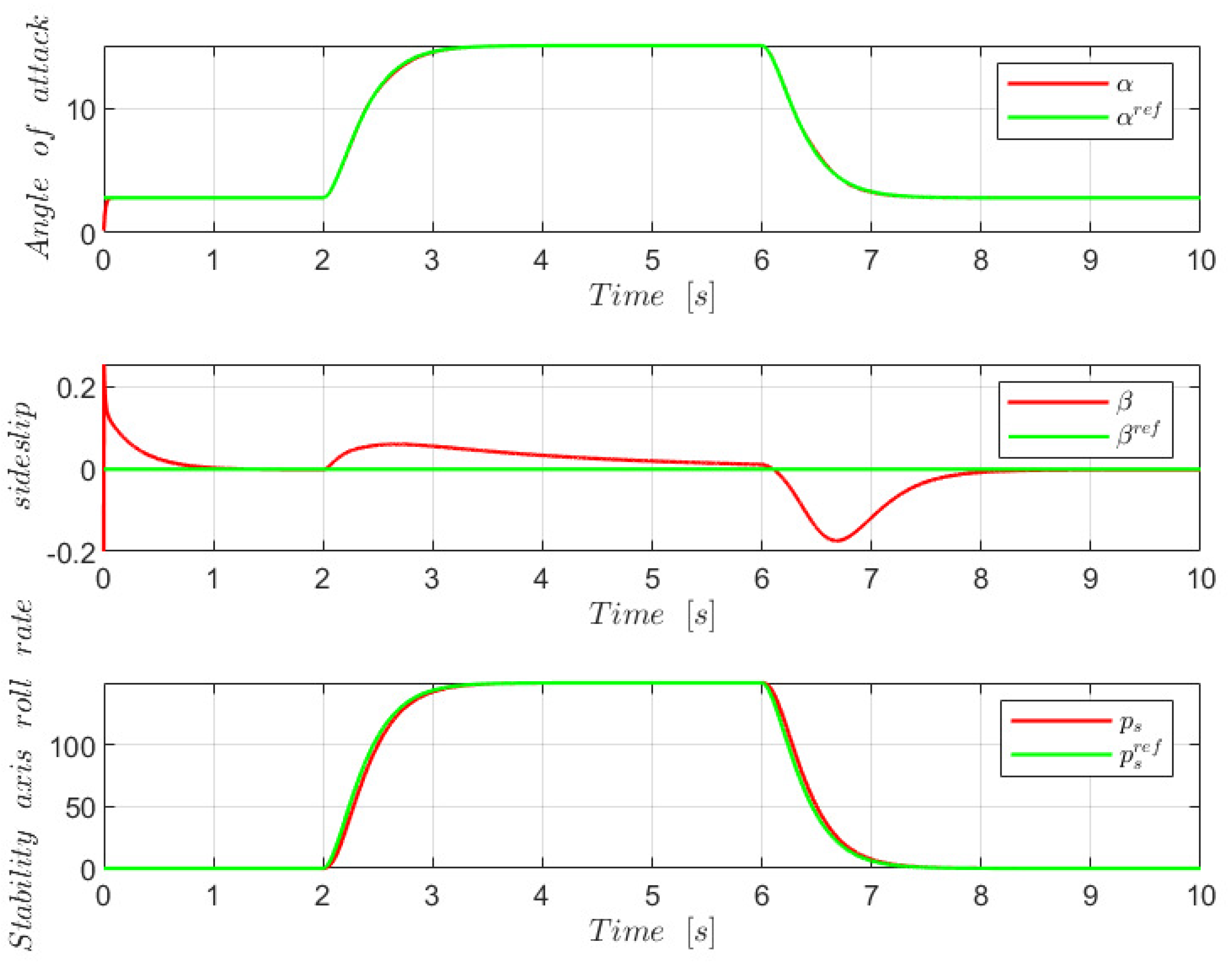
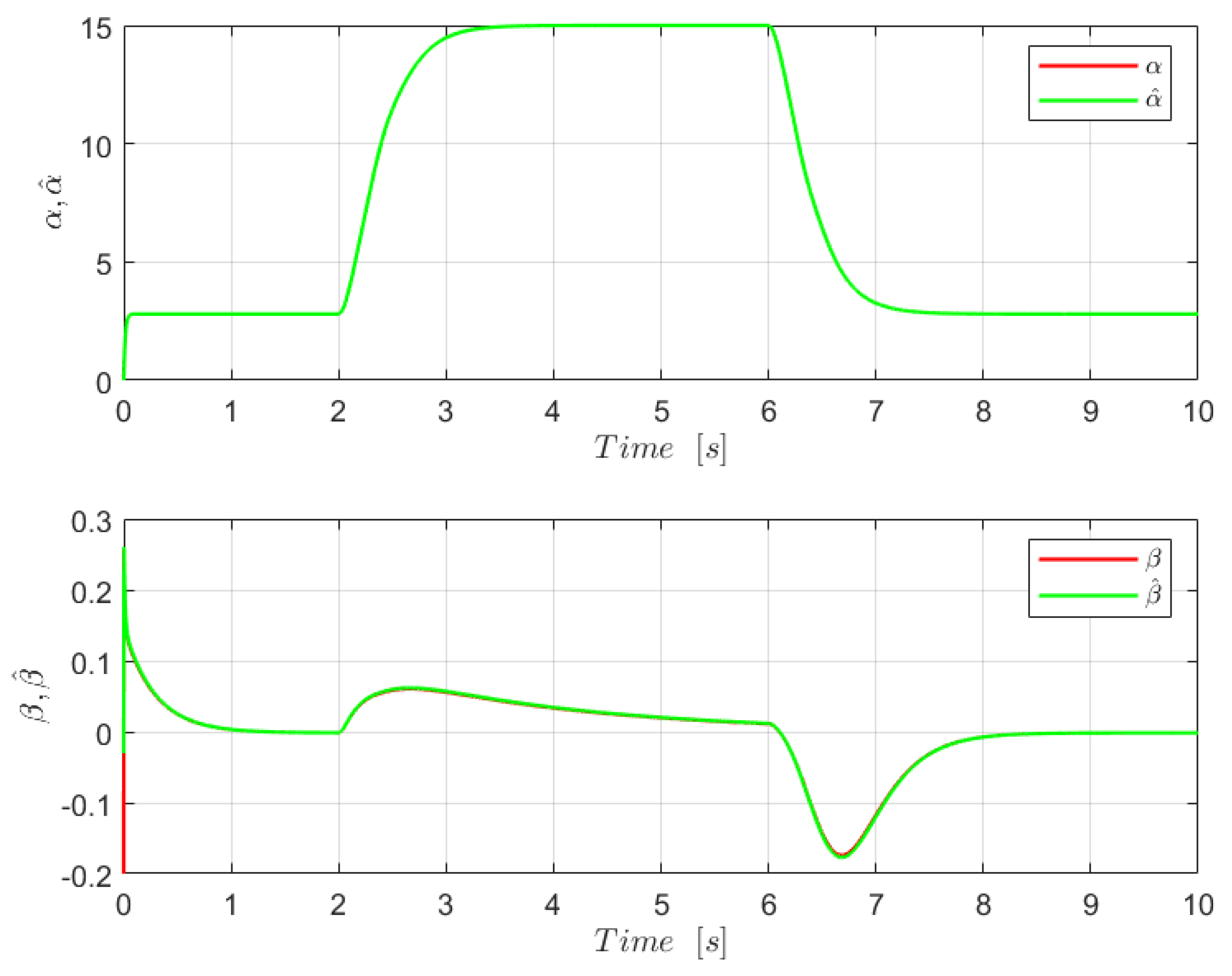
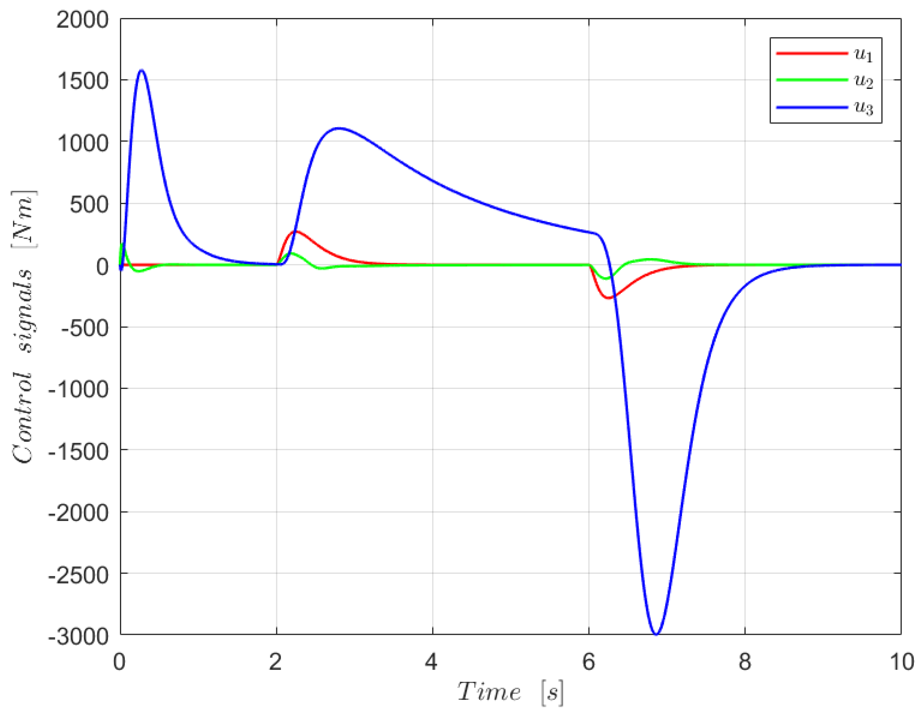
4. Simulation Results and Discussion

In the simulations, an Admire, a MATLAB/SIMULINK environment for the (GAM) [28] is considered with properties summarized in Table 1.
A flight scenario in which the aircraft is in level flight at Mach 0.5 and a height of 1000 m was chosen for the simulations. The simulations included actuator and sensor dynamics that were not included in the previous design. Additionally, Euler angles were given such small values. The total velocity ranges between 100 and 170 km/h, with F T = 500 N.
For the control law parameters were set c α = 75 , c β = 50 , c p s = 25 for the backstepping approach and K 02 = γ ϵ 2 for the second equation of the observer, where γ = 1 and ϵ = 0.001 . Figure 3 illustrates the trajectory tracking simulation results for such an angle of attack, slideslip, and stability axis roll rate, and it is obvious that each of the latter variable graphs properly follows the prescribed path. Both α and β are shown in Figure 4 with their estimates, resulting in a perfect estimation of the observer chosen. For the control input, it is presented in Figure 5.

5. Conclusions

In this study, a nonlinear observer backstepping design technique for fighter aircraft control is presented in order to achieve control objectives in the presence of nonlinear lift and side forces. According to the Lyapunov stability theorem, the resultant closed-loop system is exponentially stable for trajectory tracking errors. The simulation results of Admire model seemed to be excellent using this design technique. Furthermore, the observer perfectly estimates the state vector.

Author Contributions

Conceptualization, B.M.S.; methodology, B.M.S.; software, B.M.S. and B.M.; writing—original draft preparation, B.M.S.; writing—review and editing, B.M.S., B.M. and B.A. All authors have read and agreed to the published version of the manuscript.

Funding

This work was supported by the Directorate-General for Scientific Research and Technological Development/Ministry of High Education and Scientific Research of Algeria (DGRSDT/MESRS).

Institutional Review Board Statement

Not applicable.

Informed Consent Statement

Not applicable.

Data Availability Statement

Not applicable.

Conflicts of Interest

The authors declare no conflict of interest.

Abbreviations

The following abbreviations are used in this manuscript:
FOCField-Oriented Control
OIBObserved-Integrator Backstepping
NDMNonlinear Damping-Matched
GAMGeneric Aerodata Mode

References

  1. Kokotovic, P.V. The joy of feedback: Nonlinear and adaptive. IEEE Control Syst. Mag. 1992, 12, 7–17. [Google Scholar]
  2. Kanellakopoulos, I.; Kokotovic, P.; Morse, A. A toolkit for nonlinear feedback design. Syst. Control Lett. 1992, 18, 83–92. [Google Scholar] [CrossRef]
  3. Harrouz, A.; Becheri, H.; Colak, I.; Kayisli, K. Backstepping control of a separately excited DC motor. Electr. Eng. 2018, 100, 1393–1403. [Google Scholar] [CrossRef]
  4. Abdulgalil, F.; Siguerdidjane, H. Backstepping design for controlling rotary drilling system. In Proceedings of the 2005 IEEE Conference on Control Applications, CCA 2005, Toronto, ON, Canada, 28–31 August 2005; pp. 120–124. [Google Scholar]
  5. Hu, J.; Dawson, D.; Qian, Y. Position tracking control for robot manipulators driven by induction motors without flux measurements. IEEE Trans. Robot. Autom. 1996, 12, 419–438. [Google Scholar]
  6. Hu, J.; Dawson, D.; Anderson, K. Position control of a brushless DC motor without velocity measurements. IEE Proc.-Electr. Power Appl. 1995, 142, 113–122. [Google Scholar] [CrossRef]
  7. Xiong, P.; Sun, D. Backstepping-based DPC strategy of a wind turbine-driven DFIG under normal and harmonic grid voltage. IEEE Trans. Power Electron. 2015, 31, 4216–4225. [Google Scholar] [CrossRef]
  8. Nadour, M.; Essaki, A.; Nasser, T. Comparative analysis between PI & backstepping control strategies of DFIG driven by wind turbine. Int. J. Renew. Energy Res. 2017, 7, 1307–1316. [Google Scholar]
  9. Bossoufi, B.; Karim, M.; Lagrioui, A.; Taoussi, M.; Derouich, A. Observer backstepping control of DFIG-Generators for wind turbines variable-speed: FPGA-based implementation. Renew. Energy 2015, 81, 903–917. [Google Scholar] [CrossRef]
  10. Kahveci, N.E.; Ioannou, P.A. Adaptive steering control for uncertain ship dynamics and stability analysis. Automatica 2013, 49, 685–697. [Google Scholar] [CrossRef]
  11. Strand, J.P.; Ezal, K.; Fossen, T.I.; Kokotović, P.V. Nonlinear control of ships: A locally optimal design. IFAC Proc. Vol. 1998, 31, 705–710. [Google Scholar] [CrossRef]
  12. Binh, N.T.; Tung, N.A.; Nam, D.P.; Quang, N.H. An adaptive backstepping trajectory tracking control of a tractor trailer wheeled mobile robot. Int. J. Control Autom. Syst. 2019, 17, 465–473. [Google Scholar] [CrossRef]
  13. Truong, T.N.; Vo, A.T.; Kang, H.-J. A backstepping global fast terminal sliding mode control for trajectory tracking control of industrial robotic manipulators. IEEE Access 2021, 9, 31921–31931. [Google Scholar] [CrossRef]
  14. Belkheiri, M.; Boudjema, F. Backstepping control augmented by neural networks for robot manipulators. In Proceedings of the AIP Conference Proceedings of First Mediterranean Conference on Intelligent Systems and Automation, American Institute of Physics, Annaba, Algeria, 30 June–2 July 2008; pp. 115–119. [Google Scholar]
  15. Belkheiri, M.; Boudjema, F. Neural network augmented backstepping control for an induction machine. Int. J. Model. Identif. Control 2008, 5, 288–296. [Google Scholar]
  16. Labbadi, M.; Cherkaoui, M. Robust adaptive backstepping fast terminal sliding mode controller for uncertain quadrotor UAV. Aerosp. Sci. Technol. 2019, 93, 105306. [Google Scholar] [CrossRef]
  17. Su, Z.; Wang, H.; Yao, P.; Huang, Y.; Qin, Y. Back-stepping based anti-disturbance flight controller with preview methodology for autonomous aerial refueling. Aerosp. Sci. Technol. 2017, 61, 95–108. [Google Scholar] [CrossRef]
  18. Singh, S.N.; Chandler, P.; Schumacher, C.; Banda, S.S.; Pachter, M. Nonlinear adaptive close formation control of unmanned aerial vehicles. Dyn. Control 2000, 10, 179–194. [Google Scholar] [CrossRef]
  19. Singh, S.N.; Steinberg, M. Adaptive control of feedback linearizable nonlinear systems with application to flight control. J. Guid. Control Dyn. 1996, 19, 871–877. [Google Scholar] [CrossRef]
  20. Steinberg, M.L.; Page, A.B. Nonlinear adaptive flight control with genetic algorithm design optimization. Int. J. Robust Nonlinear Control 1999, 9, 1097–1115. [Google Scholar] [CrossRef]
  21. Krstic, M.; Kokotovic, P.V.; Kanellakopoulos, I. Nonlinear and Adaptive Control Design, 1st ed.; John Wiley & Sons, Inc.: New York, NY, USA, 1 October 1995. [Google Scholar]
  22. Herbst, W.B. Future fighter technologies. J. Aircr. 1980, 17, 561–566. [Google Scholar] [CrossRef]
  23. Well, K.; Faber, B.; Berger, E. Optimization of tactical aircraft maneuvers utilizing high angles of attack. J. Guid. Control Dyn. 1982, 5, 131–137. [Google Scholar] [CrossRef]
  24. Stevens, B.L.; Johnson, E.N.; Lewis, F.L. Aircraft Control and Simulation; Wiley: New York, NY, USA, 1992. [Google Scholar]
  25. Boiffier, J.-L. The Dynamics of Flight, The Equations; Wiley: New York, NY, USA, 1998. [Google Scholar]
  26. Härkegård, O.; Glad, S.T. Flight control design using backstepping. IFAC Proc. Vol. 2001, 34, 283–288. [Google Scholar] [CrossRef] [Green Version]
  27. Marino, R.; Tomei, P. Global Adaptive Observers and Output-Feedback Stabilization for a Class of Nonlinear Systems; Springer: Berlin/Heidelberg, Germany, 1991; pp. 455–493. [Google Scholar]
  28. Backström, H. Report on the usage of the Generic Aerodata Model; Saab Aircraft AB: Linkoping, Sweden, 1997. [Google Scholar]
Figure 1. Lateral control objectives.
Engproc 29 00003 g001
Figure 2. Typical lift force coefficient vs. angle of attack and side force coefficient vs. sideslip characteristics.
Engproc 29 00003 g002
Figure 3. Simulated aircraft control objectives.
Engproc 29 00003 g003
Figure 4. State estimation.
Engproc 29 00003 g004
Figure 5. Control signals.
Engproc 29 00003 g005
Table 1. GAM Properties.
EntityValues
Mass (m)9100 (kg)
Wing planform area (S)45 (m)
Density of the airflow ( ρ )1.08 (kg/m 3 )
Disclaimer/Publisher’s Note: The statements, opinions and data contained in all publications are solely those of the individual author(s) and contributor(s) and not of MDPI and/or the editor(s). MDPI and/or the editor(s) disclaim responsibility for any injury to people or property resulting from any ideas, methods, instructions or products referred to in the content.

