Article

Research on the Influence of Negative KERMA Factors on the Power Distribution of a Lead-Cooled Fast Reactor

School of Nuclear Science and Engineering, North China Electricity Power University, Beinong Road, Beijing 102206, China
*
Author to whom correspondence should be addressed.
J. Nucl. Eng. 2024, 5(1), 1-12; https://doi.org/10.3390/jne5010001
Submission received: 23 September 2023 / Revised: 30 November 2023 / Accepted: 9 December 2023 / Published: 21 December 2023
(This article belongs to the Special Issue Monte Carlo Simulation in Reactor Physics)

Abstract

:
The accurate calculation of reactor core heating is vital for the design and safety analysis of reactor physics. However, negative KERMA factors may be produced when processing and evaluating libraries of the nuclear data files ENDF/B-VII.1 and ENDF/B-VIII.0 with the NJOY2016 code, and the continuous-energy neutron cross-section library ENDF71x with MCNP also has the same problem. Negative KERMA factors may lead to an unreasonable reactor heating rate. Therefore, it is important to investigate the influence of negative KERMA factors on the calculation of the heating rate. It was also found that negative KERMA factors can be avoided with the CENDL-3.2 library for some nuclides. Many negative KERMA nuclides are found for structural materials; there are many non-fuel regions in fast reactors, and these negative KERMA factors may have a more important impact on the power distribution in non-fuel regions. In this study, the impact of negative KERMA factors on power calculation was analyzed by using the RBEC-M benchmark and replacing the neutron cross-section library containing negative KERMA factors with one containing normal KERMA factors that were generated based on CENDL-3.2. For the RBEC-M benchmark, the deviation in the maximum neutron heating rate between the negative KERMA library and the normal library was 6.46%, and this appeared in the reflector region. In the core region, negative KERMA factors had little influence on the heating rate, and the deviations in the heating rate in most assemblies were within 1% because the heating was mainly caused by fission. However, in the reflector zone, where gamma heating was dominant, the total heating rate varied on account of the gamma heating rate. Therefore, negative KERMA factors for neutrons have little influence on the calculation of fast reactor heating according to the RBEC-M benchmark.

1. Introduction

A lead-cooled fast reactor (LFR) is a liquid-metal-cooled reactor operating in the fast neutron spectrum and is one of the six types of advanced reactor systems that were selected in the Generation-IV program due to their promise of achieving the goals of improved safety, sustainability, efficiency, and cost in contrast to earlier reactor generations [1]. The RBEC-M lead–bismuth-cooled fast reactor benchmark was suggested as part of an IAEA CRP on the “Development of Small Reactors without On-site Refueling”. MOCUP-coupled MCNP-4C and ORIGEN2.1 utility codes with the MCNP data libraries based on the ENDF/B-VI evaluations—and TRITON-coupled KENO-V.a and ORIGENS codes with a library with 238 groups based on ENDF/B-V.2—were the computational tools used to simulate this benchmark. There are numerous uncertainties in the prediction of the core parameters of these reactor designs that arise from approximations used in the solution of the transport equation, in nuclear data processing, and in the generation of cross-section libraries [2].
Heating is a very important parameter for nuclear systems. It may affect the design of peripheral systems, such as shields and structural components. In reactor design, the accurate calculation of the reactor heating rate makes sense for the improvement of a reactor’s economy [3]. When determining a nuclear reactor’s design limits, such as the peak cladding temperature and peak cladding thermal stress, an accurate assessment of the heat generation rate (power) is necessary. Accurate heat release calculations can help us understand the safety margins of reactors, thereby further improving their economy while ensuring safety in their design. In reactors, the nuclear reactions in which neutrons interact with matter and produce a recoil nucleus and various lightly charged particles, including protons and deuterons, deposit heat in structural materials. Similarly, the interactions of photons and matter also deposit heat. All charged particles and recoil nuclei deposit their kinetic energy, which is estimated as the heating of neutrons or photons. This phenomenon is known as ‘kinetic energy release in materials’ or KERMA [4]. In a fast reactor, the reactor’s heating is mainly composed of two parts: neutron heating and gamma heating. In fuel assemblies, neutron heating is dominant, accounting for about 90%, and gamma heating accounts for 10%. However, in non-fuel assemblies, gamma heating accounts for nearly 90%. The KERMA factor is of great importance for the accuracy of reactor heating calculations.
KERMA factor calculations have been investigated around the world, and many codes have been developed, such as MACK [5], MAZE [6], KAOS-V [7], CRad [8], NJOY [9], and NECP-Atlas [10]. Three methods are applied with these codes, namely, the direct calculation method, the energy balance method, and the kinematic method. Only the kinematic method was used in earlier codes because part of the spectrum of the emitted particles was lacking in earlier evaluated neutron nuclear data files. With the release of ENDF/B-IV, the addition of secondary photons made it possible to apply the energy balance method. The basic principle of the energy balance method is that the energy carried by charged particles is equal to the total energy released in a nuclear reaction minus the energy carried away by neutrons and photons. With the development and enrichment of data on charged particles and recoil nuclei, it is possible to obtain KERMA factors by adding the energy of all charged particles, which is called the direct method. For the calculation of KERMA factors, the kinematic method is applied in the MACK code [11], and the kinematic method and energy method are applied in the KAOS-V [12] code. The widely used nuclear data processing code NJOY2016 applies different methods for different nuclides. However, the absence of some nuclear data and defects in NJOY2016 lead to the calculation of negative KERMA factors, which are unreasonable. The reasons for these negative KERMA factors can be summarized as follows: the nuclear data that are evaluated and the calculation method applied. The NECP of Xi’an Jiaotong University [8] and the Japan Atomic Energy Agency [13,14] analyzed the negative KERMA factors produced with different nuclear data. The reasons can be summarized as follows: (1) incorrect Q-values; (2) missing angular distributions of the energy of secondary neutrons and charged particles; (3) erroneous or over-counted photon yields. An ACE data library called ENDF71x based on ENDF/B-VII.1 was processed with the NJOY code, and it was distributed through the Radiation Safety Information Computational Center (RSICC) along with MCNP6. Many nuclides in the ENDF71x library also have the same issue with negative KERMA factors [15]. However, the NJOY2016 manual states that a negative KERMA coefficient is not always the defect that it seems to be. It must be remembered that heating has both neutron and photon components. A negative KERMA factor might indicate that too much energy has been included with the production of photons in the evaluation. This will result in excessive photon heating if most of the photons stay in the system. However, negative KERMA factors will have just the right magnitude to cancel this excess heating. The energy balance method guarantees the conservation of the total energy in large homogeneous systems. However, evaluation libraries for photon data (mainly atomic reactions of photons in a nuclear reactor system) are processed using different modules, and this complementary effect is almost impossible to apply in practical engineering design.
When negative KERMA factors are applied in reactor simulation, the heating rate of the simulation results may lead to unphysical results, or fail to accurately represent the real power in the core. To investigate the impact of negative KERMA factors on heating calculations, the (A Compact ENDF (ACE) library based on ENDF/B-VII.1 [16] has been examined, and the negative KERMA factors have been identified. Furthermore, the CENDL-3.2 [17,18] database has been processed using NJOY2016 [19] and the accompanying KERMA factors have been checked to ensure that the desired cross-sections in ENDF/B-VII.1 are replaced with corresponding ones that adhere to the physical principles. In addition, the effect of negative KERMA factors is discussed by utilizing the MCNP [20] code to calculate the heating in the lead fast reactor benchmark RBEC-M. Apart from RBEC-M, various types of lead-cooled fast reactors (LFR) have also been developed [21]. These LFRs operate on plutonium fuel with admixed minor actinides in an adiabatic equilibrium state. The reactors function in breeder mode to sustain themselves with plutonium and also consume self-produced minor actinides, thereby exhibiting adiabaticity. Thus, they fulfill both of the aforementioned requirements and are considered as promising options for meeting the long-term global energy demand.
This study focuses on investigating the influence of negative KERMA factors on the calculation of heating rates in a lead-cooled fast reactor. Section 2 presents the method of calculating heating rates using neutron and photon KERMA factors, as well as neutron flux and photon flux. Some nuclides with negative KERMA factors, based on ENDF/B-VIII.0 and ENDF/B-VII.1 with the nuclear process code NJOY2016, are provided. The KERMA factors of ENDF/B-VIII.0 and ENDF/B-VII.1 are compared with those of CENDL-3.2. For certain nuclides, the KERMA factors of CENDL-3.2 exhibit more reasonable values compared to those of ENDF/B-VII.1 and ENDF/B-VIII.0. The influence of negative KERMA factors on the power distribution of the lead-cooled fast reactor (RBEC-M benchmark) is studied using the neutron transport model and the neutron-photon coupled transport model. The conclusions are presented in Section 5.

2. Heating Calculation Using KERMA Factor

Since negative KERMA factors primarily arise from nuclear reactions caused by neutrons, the subsequent sections of this paper will primarily focus on the calculation of neutron KERMA factors. The calculation method for photon KERMA factors is similar to that of neutron KERMA factors, but with different reactions taken into consideration. The neutron and gamma heating rates at a specific location in the reactor, determined by KERMA factors, can be calculated using the following equations:
H n ( r ) = ϕ n r , E i N i r k i , n E d E
H γ ( r ) = ϕ γ r , E i N i r k i , γ E d E
where ϕ n r , E and ϕ γ r , E represent the neutron flux and photon flux at location r with energy E, respectively. N i and k i are the atomic density and total neutron KERMA factor or photon KERMA factor of nuclide i. The total heating is the summary of neutron and photon heating. In the MCNP calculation, if the neutron KERMA factor is negative, the neutron KERMA factor will be set as zero [17].

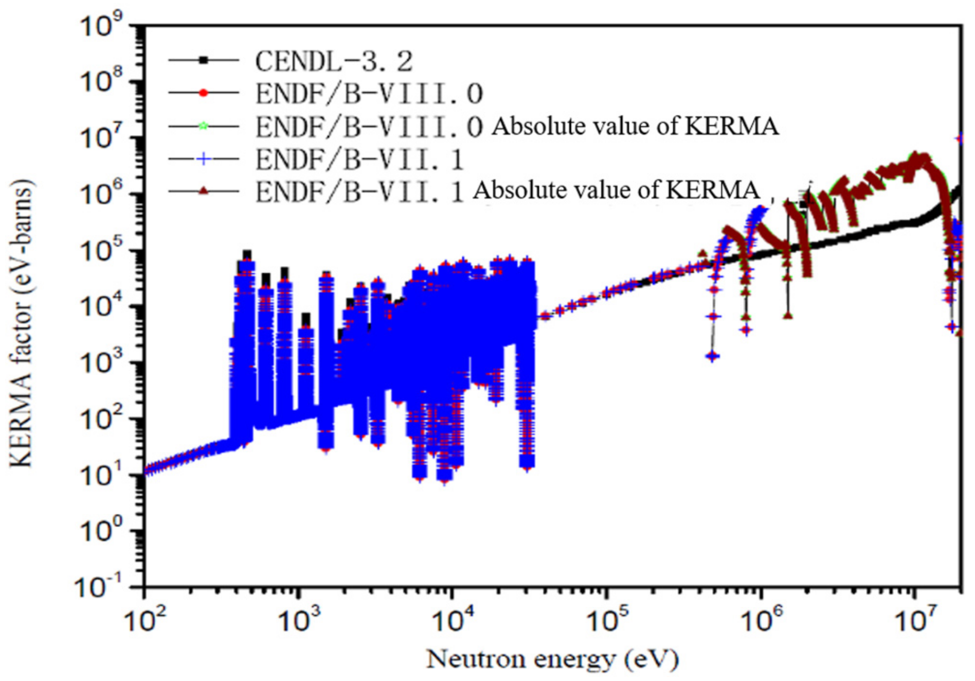
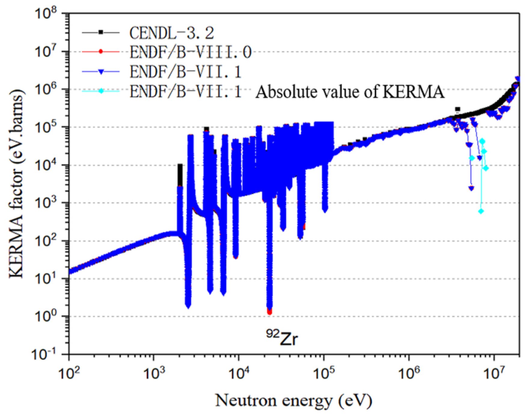
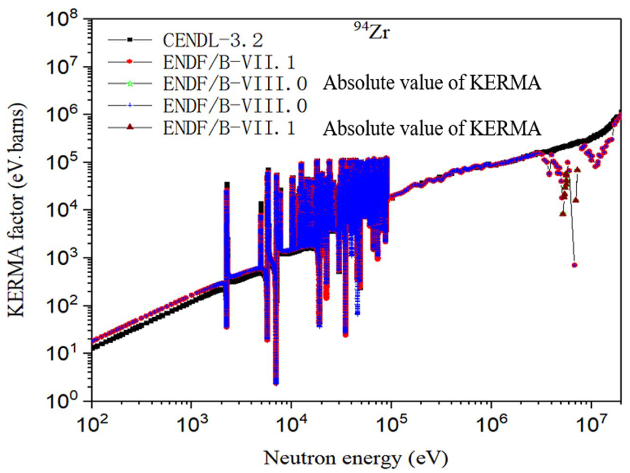
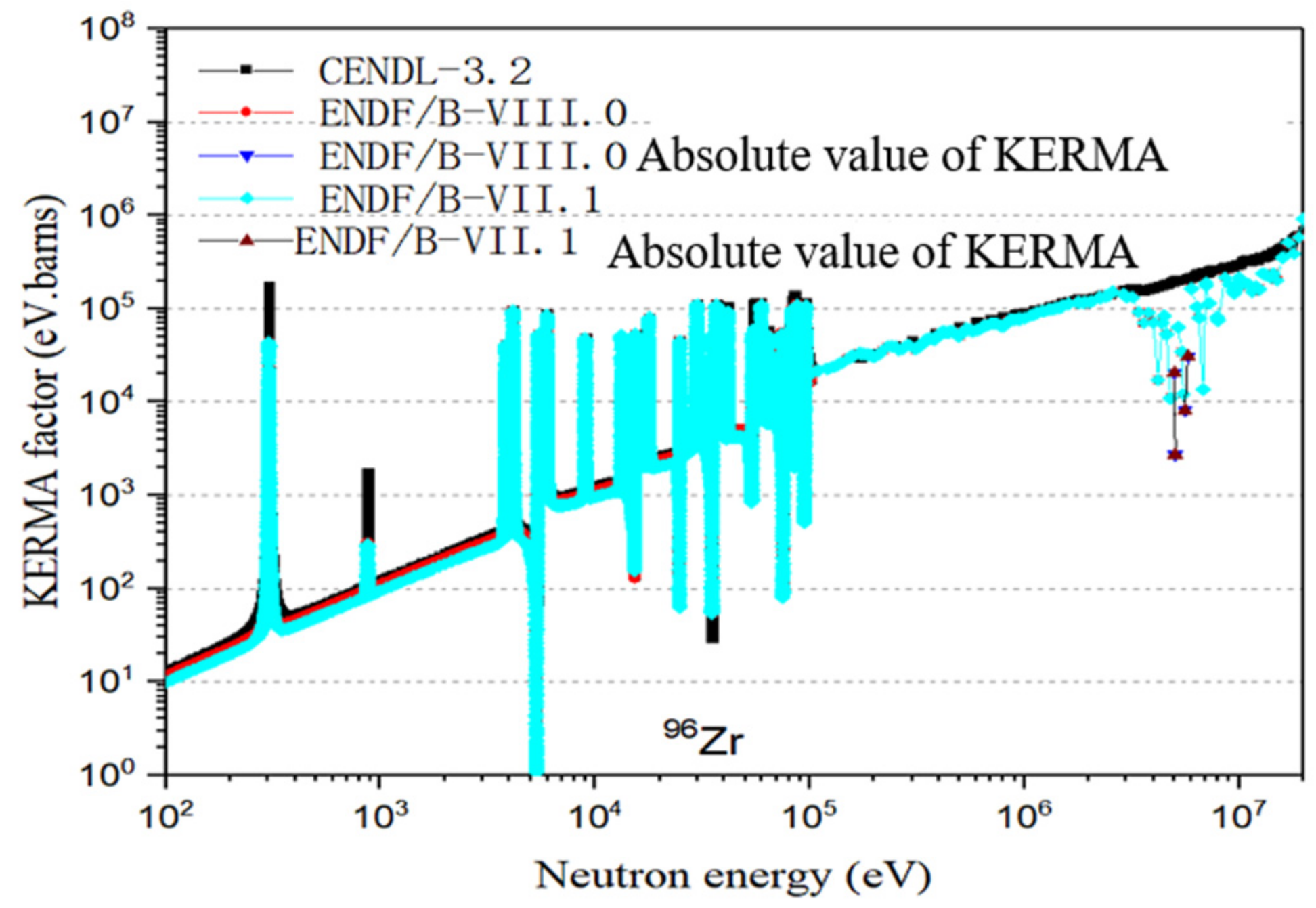
3. Nuclides with Negative KERMA Factors in ENDF/B-VII.1

Although all three methods are available in the NJOY2016 code, the energy balance method is predominantly used to determine KERMA factors in most nuclides. However, when this method is applied, it can lead to negative KERMA factors due to deficiencies in NJOY or inconsistencies in evaluated nuclear data (Table 1). The neutron KERMA factors can be negative in ENDF/B-VII.1 and ENDF/B-VIII.0, but they are reasonable in CENDL-3.2 when processed using NJOY2016.
Figure 1, Figure 2, Figure 3, Figure 4 and Figure 5 present a comparison of KERMA factors from different evaluated nuclear data files. For clarity, negative KERMA factors are represented by their absolute values. From the figures, it can be observed that isotopes such as 92Mo, 98Mo, 92Zr, 95Zr, and 96Zr, based on ENDF/B-VII.1 and ENDF/B-VIII.0, exhibit negative KERMA factors in the high-energy range, whereas the KERMA factors from CENDL-3.2 are consistently positive and display more reasonable trends.
For example, considering 92Mo, the anomaly arises from the MT = 3 data in FILE = 12–15. FILE = 12–14 represents the angular distribution of secondary photons and the photon spectrum, while MT = 3 data represent the summation reaction of non-elastic scattering. These specific data are inconsistent and lack energy balance, resulting in negative KERMA factors when employing the energy balance method within a particular energy range. Nuclides such as 92Mo, 98Mo, 92Zr, 95Zr, and 96Zr are key constituents in structural materials. Therefore, negative KERMA factors may significantly impact the heating rate of these materials.

4. Numerical Verification and Analysis

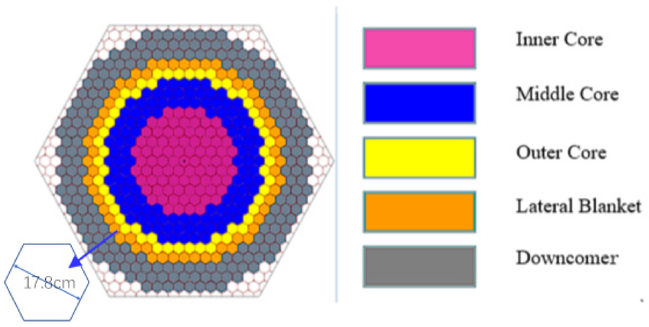
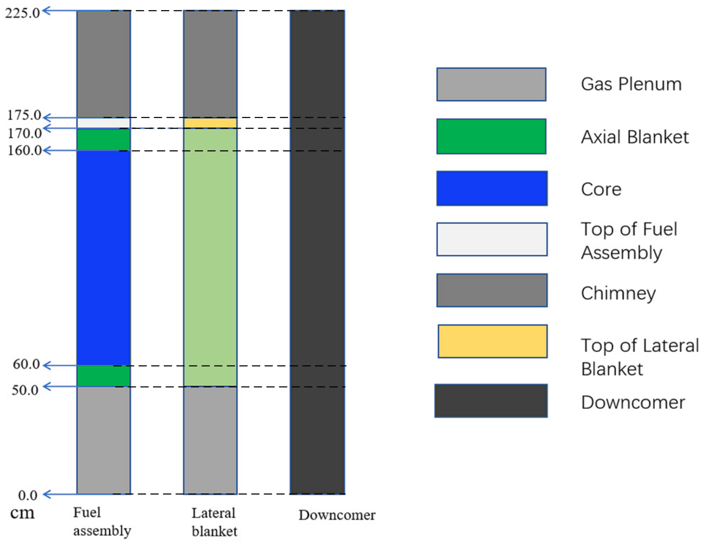
4.1. Introduction for RBEC-M Benchmark

To investigate the influence of negative KERMA factors on reactor heating calculations, the RBEC-M lead fast reactor benchmark [22] is utilized. The core and assemblies of RBEC-M are illustrated in Figure 6 and Figure 7. The RBEC-M consists of three homogenized core zones with different compositions, each having the same enrichment but varying fuel volume fractions. The fuel employed is a mixture of uranium–plutonium nitride, (U0.863 + Pu0.137)N, consisting of reactor-grade plutonium recovered from typical light water reactor spent fuel and depleted uranium with 0.1 wt.% U-235. Lateral (radial) and axial blankets surround the core zones, composed of depleted uranium nitride. The cladding and structural materials consist of ferritic/martensitic stainless steel, EP-823 (12% Cr-Si), and the coolant material used is lead–bismuth eutectic. The choice of a lead fast reactor is due to the fact that the coolant contains substantial amounts of 209Bi, which has negative KERMA factors in the ENDF/B-VII.1 files. Additionally, the structural materials contain significant quantities of isotopes of Nb and Mo, which also affect nuclear heating calculation.
Table 2 and Table 3 display the nuclear density of the components in the RBEC-M benchmark. It can be observed that the structural materials contain isotopes of Mo and Nb. In various types of stainless steel, a certain amount of Mo may be added to modify the material’s corrosion resistance.
To assess the impact of negative KERMA factors on reactor heating, the MCNP code is employed for the calculations. Two cases are considered: in case 1, an ACE format continuous point cross-section library based on ENDF/B-VII.1 (ENDF71x) is used, including nuclides with negative KERMA factors. In case 2, partial ACE files of these nuclides with negative KERMA factors, obtained from the CENDL-3.2 data processed by the NJOY2016 code, are used to replace the library with negative KERMA factors. The specific replaced nuclides are listed in Table 4. These nuclides constitute the main components of structural materials and coolants, accounting for 15–50% of the total atomic density in various assemblies. These nuclides can influence power calculations.
A KCODE run is utilized in the MCNP calculation, with input parameters set to 400,000 source histories per cycle and 400 cycles, where the first 50 cycles are inactive. This configuration aims to minimize calculation errors and control the time required for computation. The results for the effective multiplication factor (keff) for different cases are presented in Table 5. It can be observed from the table that due to the replacement of ACE format cross-sections for seven nuclides, there is a difference of 347 pcm in the effective multiplication factor. This discrepancy is primarily attributed to differences in neutron cross-sections between the evaluation libraries of ENDF/B-VII.1 and CENDL-3.2.
When performing heating calculations using the MCNP code, two options are employed: neutron calculation and coupled neutron-photon transport calculation. The former uses a single F6:N tally, while the latter utilizes both F6:N and F6:P [23] tallies. The MCNP code provides three methods for heating calculations: F6:N, F6:P, and F7:N. The F6 tally follows the same theory as Equations (1) and (2). The F6:N tally accounts for the energy of fission products and prompt neutrons, while the F6:P tally accounts for the energy of prompt gammas and capture gammas. The F7:N tally incorporates fission products, prompt gammas, and neutrons, considering only fission Q-value and fission cross-sections. The difference between F7:N and F6:N is that the former assumes all fission energy is deposited locally, which means there are no results in assemblies without fuel. However for the F6:N, the neutron can transport to the nonfuel region, and deposit the energy into the nonfuel region.

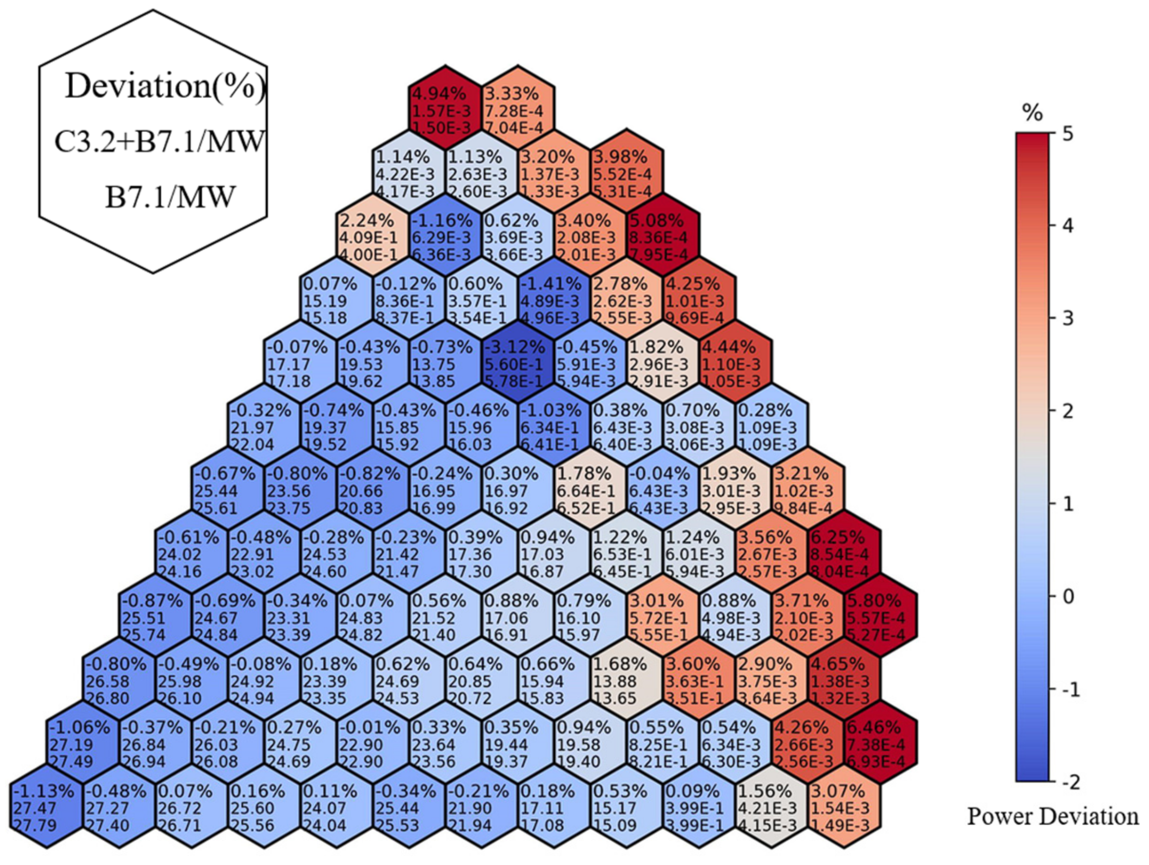
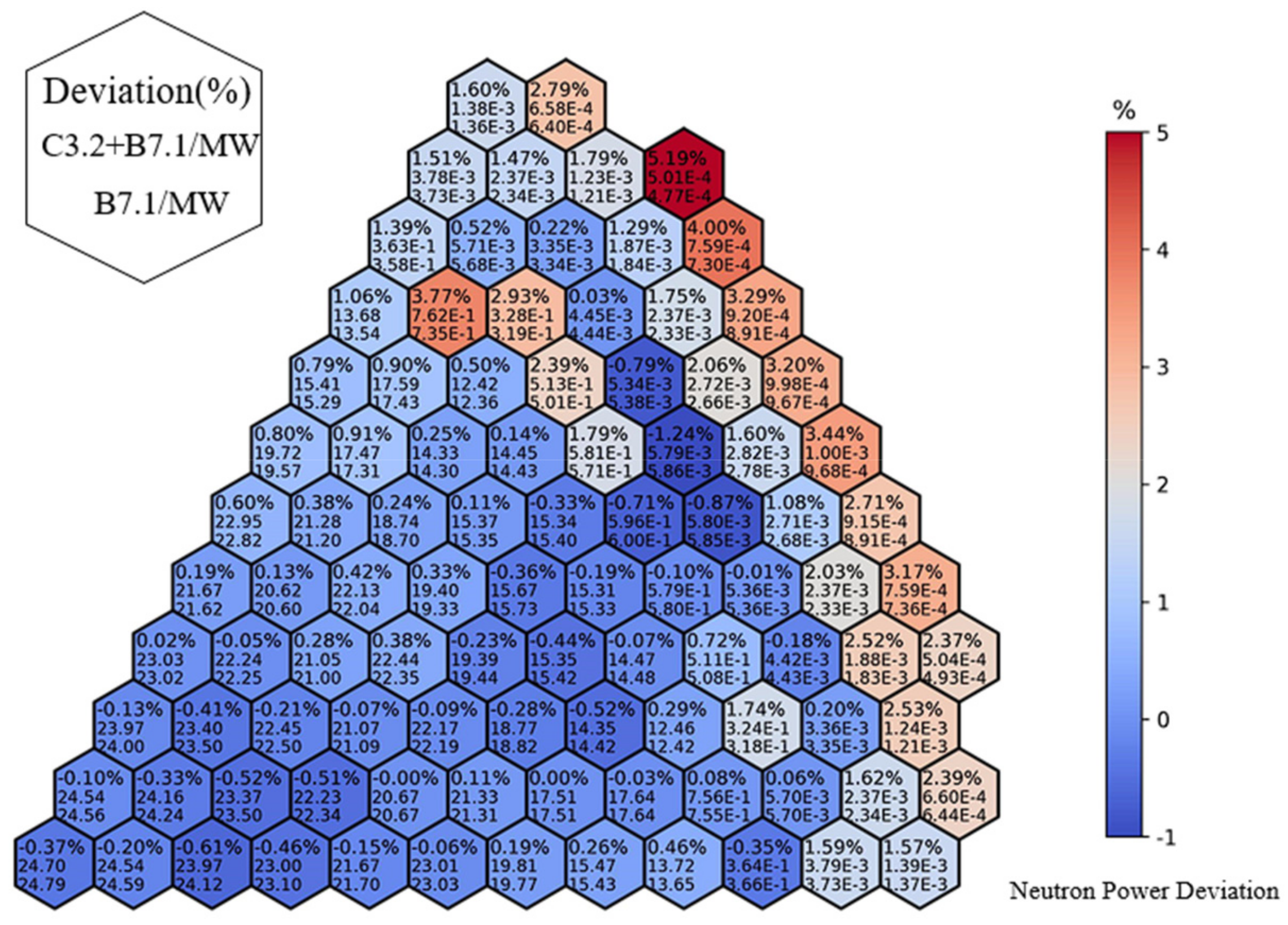
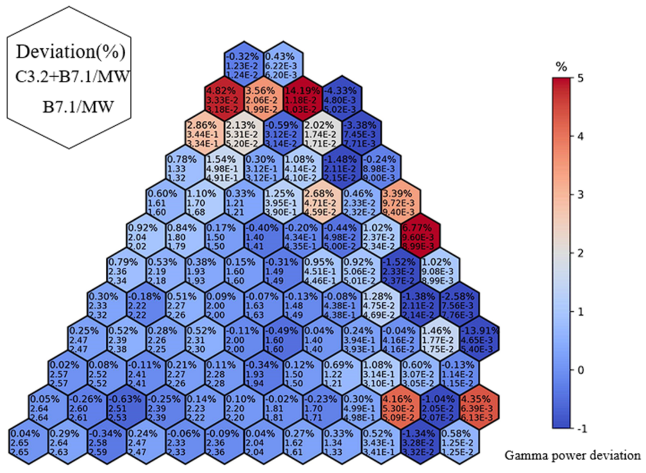
4.2. The Neutron Power Distribution Comparison

To investigate the effect of neutron KERMA factors on power distribution, the F6:N tally is used based on the available heating tallies in MCNP. It is found that when considering neutron heating using the F6:N tally, any negative KERMA factors are set to zero in MCNP. The comparison between the two cases is illustrated in Figure 8, with the total power normalized to 900 MWt. The color bar represents the deviation between the two cases, with case 1 as the baseline. As shown in Figure 8, negative KERMA factors have little impact on power calculations in the core region, with deviations of less than 1% in most assemblies and statistical errors of MCNP below 1.15%. However, in the down-comer region, where heating is derived from non-fission reactions such as elastic and inelastic scattering, the calculated results exhibit relatively larger deviations of up to 6.46%, with a statistical error of the MCNP code of 0.25%. Hence, these deviations are caused by the KERMA factors. It should be noted that these results are obtained after setting negative KERMA factors to zero. If negative KERMA factors are used, the deviation in the calculated results may be larger.
The larger deviation in the non-fuel assemblies is due to the fact that the nuclides with negative KERMA factors are major components of structural materials and coolants. After replacing the nuclides with normal KERMA factors, the neutron heating increases. In the processing of the MCNP results in this study, the total power is normalized to 900 MWt. In the case 2 results, the increased power in the outer region leads to a decrease in the inner zone due to normalization issues. However, the power of the reactor is primarily derived from the fission of fuel assemblies, and the heating of the outer region only contributes to a small portion of the total power. As a result, the deviation due to the power normalization of fuel assemblies is relatively small.

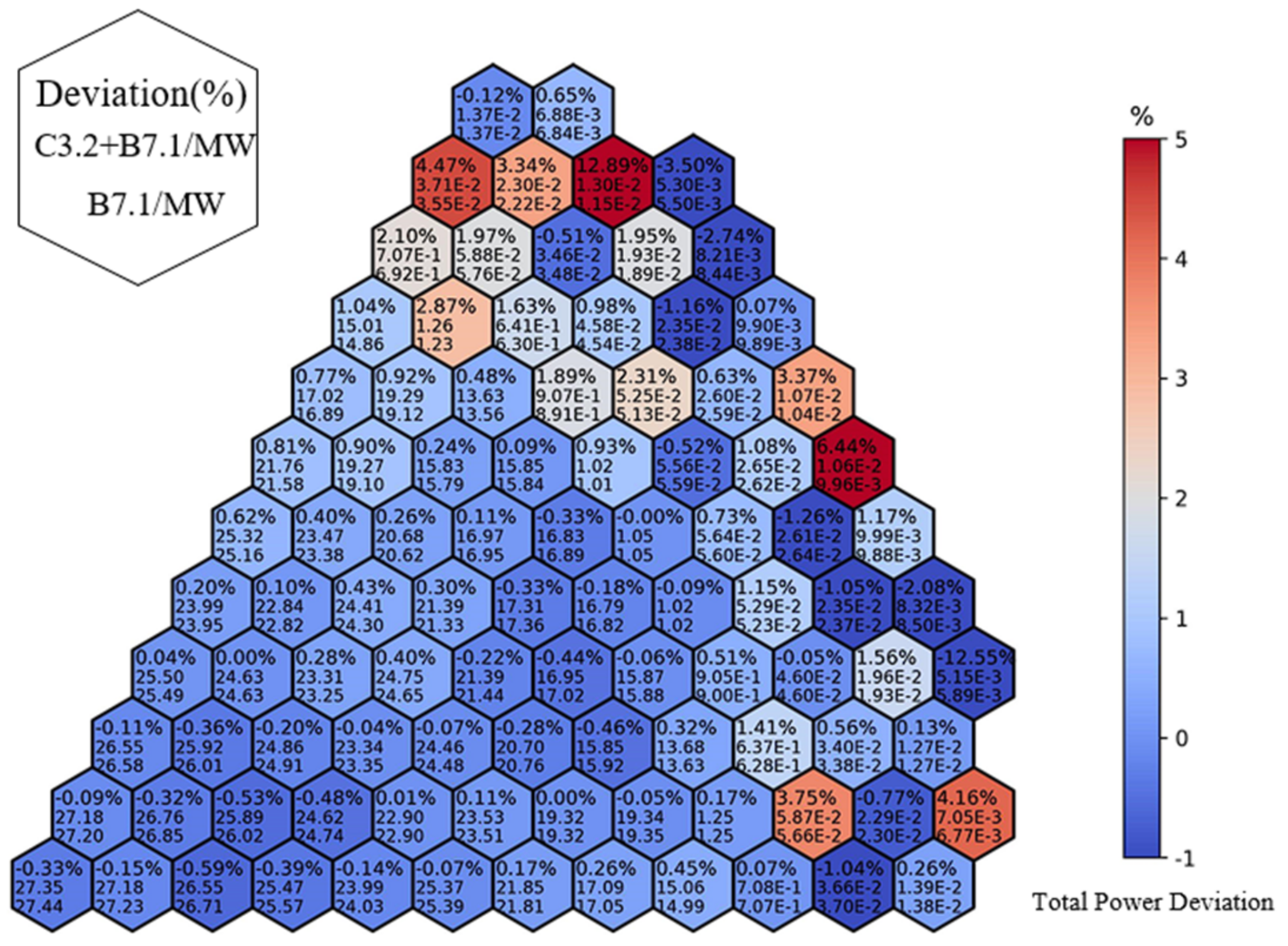
4.3. The Coupled Neutron–Photon Calculation Comparison

In the actual heating of a fast reactor, neutron heating accounts for approximately 90% [24], while gamma heating accounts for the remaining 10%. To investigate the impact of negative KERMA factors on both neutron and gamma heating, a coupled neutron–photon calculation is performed using the F6:N and F6:P tallies in the MCNP code. In this calculation, the total power is also normalized to 900 MW. The distribution of gamma power and total power is illustrated in Figure 9, Figure 10 and Figure 11, respectively.
Figure 9 displays the neutron power obtained from the coupled neutron–photon model heating calculation. As depicted, the neutron heating distribution in the coupled calculation follows the same trend as the neutron transport calculation. In the coupled calculation, neutron power accounts for 90.16%, while photon heating accounts for 9.84%. Figure 10 demonstrates that the deviations between the two cases are minimal in the fuel assemblies, while in the non-fuel assemblies, the deviations can reach a maximum of 6.77%, with a statistical error of the MCNP code of 2.1%. This discrepancy in the non-fuel assemblies is primarily caused by changes in neutron-produced photon cross-sections resulting from the replacement of cross-section files. Figure 11 presents the distribution of total power. In the core region, including the inner core, middle core, and outer core, neutron heating (mainly fission heating) dominates, while in the non-fuel assemblies, gamma heating is predominant and accounts for 80% of the total power. Thus, the deviations in gamma heating are more significant in the coupled neutron–photon heating calculation.

5. Conclusions

The effect of negative KERMA factors on reactor heating calculations is discussed. The ACE files based on ENDF/B-VII.1 (available for download on the LANL website https://nucleardata.lanl.gov/ace/endf71x, accessed on 30 November 2023) have been thoroughly examined. Subsequently, the CENDL-3.2 data are processed using the NJOY2016 code, resulting in nuclides with reasonable neutron KERMA factor data that can replace the nuclides with negative KERMA factors in the library. After replacing the nuclides with negative KERMA factors, neutron transport and coupled neutron–photon calculations are performed to analyze the deviations in neutron heating, gamma heating, and total heating of the RBEC-M benchmark. The findings are as follows: (1) negative KERMA factors have a relatively significant effect on neutron heating in non-fuel assemblies, resulting in a maximum deviation of 6.46%, whereas they have minimal impact on heating in fuel assemblies; (2) in the RBEC-M benchmark, neutron heating accounts for 90.15%, gamma heating accounts for 9.84%, and in non-fuel assemblies, gamma heating contributes to 80% of the total power; (3) negative KERMA factors have little effect on the overall heating of the fast reactor.

Author Contributions

Conceptualization of methodology, X.M. and G.J.; software, G.J.; validation, T.Z. and K.H.; writing—original draft preparation, G.J.; writing—review and editing, T.Z.; supervision, X.M.; project administration, X.M. All authors have read and agreed to the published version of the manuscript.

Funding

This research was funded by National Natural Science Foundation of China, grant number “11875128”.

Data Availability Statement

Data is contained within the article.

Conflicts of Interest

The authors declare no conflict of interest.

References

  1. Smith, G.F.; Cinotti, L. Handbook of Generation IV Nuclear Reactors, 2nd ed.; Lead-Cooled Fast Reactors (LFRs); Woodhead Publishing: Sawston, UK, 2016. [Google Scholar]
  2. Milosevic, M.; Greenspan, E.; Vujic, J. Effects of uncertainties in lead cross section data in monte carlo analysis of the rbec-m lead-bismuth cooled benchmark. In Proceedings of the Conference on Electronics, Telecommunications, Computing, Automation and Nuclear Technique-ETRAN, Palić, Serbia, 4–8 June 2007. [Google Scholar]
  3. Park, H.; Jeon, B.K.; Yang, W.S.; Smith, M.A.; Lee, C.H.; Lell, R.M. Verification and validation tests of gamma library of MC2-3 for coupled neutron and gamma heating calculation. Ann. Nucl. Energy 2020, 146, 107609. [Google Scholar] [CrossRef]
  4. Muir, D.W. Gamma Rays, Q-Values, and Kerma Factors; No. LA-6258-MS; Los Alamos Scientific Lab.: Mexico, NY, USA, 1976. [Google Scholar]
  5. Abdou, M.A.; Maynard, C.W. Calculational methods for nuclear heating-part I: Theoretical and computational algorithms. Nucl. Sci. Eng. 1975, 56, 360–380. [Google Scholar] [CrossRef]
  6. Zhang, L.; Abdou, M.A. Kerma factor evaluation and its application in nuclear heating experiment analysis. Fusion Eng. Des. 1997, 36, 479–503. [Google Scholar] [CrossRef]
  7. Farawila, Y.; Gohar, Y.; Maynard, C. KAOS-V Code: An Evaluation Tool for Neutron Kerma Factors and Other Nuclear Responses; Argonne National Lab.: Lemont, IL, USA, 1989. [Google Scholar]
  8. Saha, U.; Devan, K. Assessment of neutron kerma coefficients and its calculation methodologies using recent basic ENDF-6 libraries. Nucl. Eng. Des. 2020, 360, 110519. [Google Scholar] [CrossRef]
  9. Muir, D.W.; Boicourt, R.M.; Kahler, A.C. The NJOY Nuclear Data Processing System, Version 2012; Los Alamos National Laboratory: Los Alamos, NM, USA, 2012. [Google Scholar]
  10. Yin, W.; Zu, T.; Cao, L.; Wu, H. Remarks and improvements on neutron KERMA factors and radiation damage cross sections calculated by NECP-Atlas and NJOY21 using different evaluated nuclear data libraries. Ann. Nucl. Energy 2021, 164, 108624. [Google Scholar] [CrossRef]
  11. Abdou, M.A.; Maynard, C.W.; Wright, R.Q. MACK: A Computer Program to Calculate Neutron Energy Release Parameters (Fluence to Kerma Factors) and Multigroup Neutron Reaction Cross Sections from Nuclear Data in ENDF Format; Oak Ridge National Laboratory report ORNL-TM-3994; Oak Ridge National Lab.: Oak Ridge, TN, USA, 1973. [Google Scholar]
  12. Farawila, Y.; Gohar, Y.; Maynard, C. KAOS/LIB-V: A Library of Nuclear Response Functions Generated by KAOS-V Code from ENDF/B-V and Other Data Files; Argonne National Laboratory report, ANL/FPP/TM-241; Argonne National Lab.: Lemont, IL, USA, 1989. [Google Scholar]
  13. Konno, C.; Sato, S.; Ohta, M.; Kwon, S.; Ochiai, K. New remarks on KERMA factors and DPA cross section data in ACE files. Fusion Eng. Des. 2016, 109, 1649–1652. [Google Scholar] [CrossRef]
  14. Konno, C.; Tada, K.; Kwon, S.; Ohta, M.; Sato, S. Important comments on KERMA factors and DPA cross-section data in ACE files of JENDL-4.0, JEFF-3.2 and ENDF/B-VII.1. EDP Sci. 2017, 146, 2040. [Google Scholar] [CrossRef]
  15. Conlin, J.L.; Parsons, D.K.; Gardiner, S.J.; Kahler, A.C., III; Lee, M.B.; White, M.C.; Gray, M.G. Continuous Energy Neutron Cross Section Data Tables Based upon ENDF/B-VII.1; Tech. rep. LA-UR-13-20137; Los Alamos National Laboratory: Los Alamos, NM, USA, 2013. [Google Scholar]
  16. Chadwick, M.B.; Herman, M.; Obložinský, P.; Dunn, M.E.; Danon, Y.; Kahler, A.C.; Smith, D.L.; Pritychenko, B.; Arbanas, G.; Arcilla, R.; et al. ENDF/B-VII. 1 nuclear data for science and technology: Cross sections, covariances, fission product yields and decay data. Nucl. Data Sheets 2011, 112, 2887–2996. [Google Scholar] [CrossRef]
  17. Ge, Z.; Xu, R.; Wu, H.; Zhang, Y.; Chen, G.; Jin, Y.; Shu, N.; Chen, Y.; Tao, X.; Tian, Y.; et al. CENDL-3.2: The new version of Chinese general purpose evaluated nuclear data library. EDP Sci. 2020, 239, 9001. [Google Scholar] [CrossRef]
  18. Zhang, B.; Ma, X.B.; Hu, K.; Zhang, T.; Ma, X.; Chen, Y.X. Performance of the CENDL-3.2 and other major neutron data libraries for criticality calculations. Nucl. Sci. Technol. 2022, 33, 8. [Google Scholar] [CrossRef]
  19. MacFarlane, R.E.; Kahler, A.C. Methods for processing endf/b-vii with njoy. Nucl. Data Sheets 2010, 111, 2739–2890. [Google Scholar] [CrossRef]
  20. Werner, C.J.; Bull, J.S.; Solomon, C.J.; Brown, F.B.; McKinney, G.W.; Rising, M.E.; Dixon, D.A.; Martz, R.L.; Hughes, H.G.; Cox, L.J.; et al. MCNP User’s Manual, Code Version 6.2; LA-UR-17-29981; Los Alamos National Laboratory: Los Alamos, NM, USA, 2017. [Google Scholar]
  21. Stanisz, P.; Oettingen, M.; Cetnar, J. Monte Carlo modeling of Lead-Cooled Fast Reactor in adiabaticequilibrium state. Nucl. Eng. Des. 2016, 301, 341–352. [Google Scholar] [CrossRef]
  22. Sienicki, J.J.; Moisseytsev, A.; Yang, W.S.; Wade, D.C.; Nikiforova, A.; Hanania, P.; Ryu, H.J.; Kulesza, K.P.; Kim, S.J.; Halsey, W.G.; et al. Status Report on the Small Secure Transportable Autonomous Reactor (SSTAR)/Lead-cooled Fast Reactor (LFR) and Supporting Research and Development; Argonne National Lab.: Argonne, IL, USA, 2008. [Google Scholar]
  23. Peterson-Droogh, L.; Howard, R.H. Current Neutronic Calculation Techniques for Modeling the Production of Ir-192 in HFIR; Oak Ridge National Lab.: Oak Ridge, TN, USA, 2018. [Google Scholar]
  24. Lüthi, A.; Chawla, R.; Rimpault, G. Improved gamma-heating calculational methods for fast reactors and their validation for plutonium-burning configurations. Nucl. Sci. Eng. 2001, 138, 233–255. [Google Scholar] [CrossRef]
Figure 1. KERMA factors of 92Mo form different ENDFs.
Jne 05 00001 g001
Figure 2. KERMA factors of 98Mo form different ENDFs.
Jne 05 00001 g002
Figure 3. KERMA factors of 92Zr form different ENDFs.
Jne 05 00001 g003
Figure 4. KERMA factors of 94Zr form different ENDFs.
Jne 05 00001 g004
Figure 5. KERMA factors of 96Zr form different ENDFs.
Jne 05 00001 g005
Figure 6. RBEC-M core configuration.
Jne 05 00001 g006
Figure 7. RBEC-M assembly and geometry dimension in the axial direction.
Jne 05 00001 g007
Figure 8. Deviations (%) in neutron power of case 2 from those of case 1 (E-3 means × 103).
Jne 05 00001 g008
Figure 9. Deviations (%) in neutron power of case 2 from those of case 1 (E-3 means × 103).
Jne 05 00001 g009
Figure 10. Deviations (%) in gamma power of case 2 from those of case 1 (E-3 means × 103).
Jne 05 00001 g010
Figure 11. Deviations (%) in total power of case 2 from those of case 1 (E-3 means × 103).
Jne 05 00001 g011
Table 1. Nuclides with negative KERMA factors based on ENDF/B-VII.1 and ENDF/B-VIII.0 but with positive factors based on CENDL-3.2 when processing using NJOY2016.
Nuclide Name
33S93Nb145Nd174Hf
36S92Mo147Nd176Hf
92Zr94Mo147Sm177Hf
93Zr96Mo149Sm178Hf
94Zr97Mo151Sm179Hf
95Zr98Mo155Gd180Hf
96Zr133Cs165Ho209Bi
Table 2. Nuclear densities of components of physical zones.
NuclideCore 1Core 2Core 3Axial Blanket 1Axial Blanket 2Axial Blanket 3
TRU feed
Pu2381.33524 × 10−51.58166 × 10−52.18910 × 10−5
Pu2396.07226 × 10−47.19290 × 10−49.95539 × 10−4
Pu2402.43311 × 10−42.88214 × 10−43.98905 × 10−4
Pu2418.31945 × 10−59.85480 × 10−51.36396 × 10−4
Pu2424.92603 × 10−55.83513 × 10−58.07615 × 10−5
Am2418.08633 × 10−69.57866 × 10−61.32574 × 10−5
Uranium Feed
U2356.42536 × 10−67.61116 × 10−61.05343 × 10−57.47095 × 10−68.84971 × 10−61.22485 × 10⁻⁵
U2386.35962 × 10−37.53328 × 10−31.04265 × 10−27.36921 × 10−38.72919 × 10−31.20817 × 10⁻²
N Content
N-144.96797 × 10−45.88481 × 10−48.14492 × 10−44.97216 × 10−45.88976 × 10−48.15178 × 10−4
N-156.87368 × 10−38.14221 × 10−31.12693 × 10−36.87947 × 10−38.14907 × 10−31.12788 × 10−2
Coolant
Bi2091.04654 × 10−29.59466 × 10−37.46809 × 10−31.04654 × 10−29.59466 × 10−37.46809 × 10⁻³
Pb2062.06859 × 10−31.89648 × 10−31.47615 × 10−32.06859 × 10−31.89648 × 10−31.47615 × 10⁻³
Pb2071.89696 × 10−31.73913 × 10−31.35367 × 10−31.89696 × 10−31.73913 × 10−31.35367 × 10⁻³
Pb2084.49772 × 10−34.12351 × 10−33.20957 × 10−34.49772 × 10−34.12351 × 10−33.20957 × 10⁻³
Structure
C7.25829 × 10−57.75886 × 10−58.69743 × 10−57.25829 × 10−57.75886 × 10−58.69743 × 10⁻⁵
Si2.23105 × 10−42.38491 × 10−42.67341 × 10−42.23105 × 10−42.38490 × 10−42.97341 × 10⁻⁴
V3.74360 × 10−54.00178 × 10−54.48587 × 10−53.74360 × 10−54.00178 × 10−54.48587 × 10⁻⁵
Cr1.15270 × 10−31.23220 × 10−31.38125 × 10−31.15270 × 10−31.23220 × 10−31.38125 × 10⁻³
Mn6.44665 × 10−56.89124 × 10−57.72486 × 10−56.44665 × 10−56.89124 × 10−57.72486 × 10⁻⁵
Fe8.22862 × 10−38.79611 × 10−39.86016 × 10−38.22862 × 10−38.79611 × 10−39.86016 × 10⁻³
Ni6.03452 × 10−56.45069 × 10−57.23102 × 10−56.03452 × 10−56.45069 × 10−57.23102 × 10⁻⁵
Nb1.75942 × 10−51.88076 × 10−52.10827 × 10−51.75942 × 10−51.88076 × 10−52.10827 × 10⁻⁵
Mo4.25946 × 10−54.55322 × 10−55.10401 × 10−54.25946 × 10−54.55322 × 10−55.10401 × 10⁻⁵
W1.92638 × 10−52.05924 × 10−52.30834 × 10−51.92638 × 10−52.05924 × 10−52.30834 × 10⁻⁵
Table 3. Nuclear densities of components of physical zones (cont.).
Lateral
Blanket
Top of Fuel
Assembly
Gas PlenumTop of LB
Assembly
DowncomerChimney
Uranium Feed
U2351.05171 × 10−5
U2381.03738 × 10−2
NContent
N-146.99943 × 10⁻⁴
N-159.68440 × 10⁻³
Coolant
Bi2099.46070 × 10−39.52768 × 10−39.52768 × 10−39.46070 × 10−31.50701 × 10−21.66609 × 10⁻²
Pb2061.87001 × 10−31.88324 × 10−31.88324 × 10−31.87001 × 10−32.97877 × 10−33.29320 × 10⁻³
Pb2071.71485 × 10−31.72699 × 10−31.72699 × 10−31.71485 × 10−32.73162 × 10−33.01995 × 10⁻³
Pb2084.06593 × 10−34.09472 × 10−34.09472 × 10−34.06593 × 10−36.47671 × 10−37.16036 × 10⁻³
Structure
C5.88172 × 10−57.75886 × 10−52.22000 × 10−45.88172 × 10−56.25714 × 10−53.12857 × 10⁻⁶
Si1.80792 × 10−42.38491 × 10−42.38491 × 10−41.80792 × 10−41.92332 × 10−49.61659 × 10⁻⁶
V3.03361 × 10−54.00178 × 10−54.00178 × 10−53.03361 × 10−53.22724 × 10−51.61362 × 10⁻⁶
Cr9.34084 × 10−41.23220 × 10−31.23220 × 10−39.34084 × 10−49.93706 × 10−44.96853 × 10⁻⁵
Mn5.22401 × 10−56.89124 × 10−56.89124 × 10−55.22401 × 10−55.55745 × 10−52.77873 × 10⁻⁶
Fe6.66802 × 10−38.79611 × 10−38.79611 × 10−36.66802 × 10−37.09364 × 10−33.54682 × 10⁻⁴
Ni4.89004 × 10−56.45069 × 10−56.45069 × 10−54.89004 × 10−55.20217 × 10−52.60109 × 10⁻⁶
Nb1.42574 × 10−51.88076 × 10−51.88076 × 10−51.42574 × 10−51.51674 × 10−57.58370 × 10⁻⁷
Mo3.45163 × 10−54.55322 × 10−54.55322 × 10−53.45163 × 10−53.67195 × 10−51.83598 × 10⁻⁶
W1.56104 × 10−52.05924 × 10−52.05924 × 10−51.56104 × 10−51.66068 × 10−58.30338 × 10⁻⁷
Table 4. Nuclides replaced by those in CENDL-3.2.
209Bi93Nb92Mo94Mo96Mo97Mo98Mo
Table 5. keff results for using different library.
Librarykeff
ENDF/B-VII.1 (case1)1.00960 ± 0.00004
ENDF/B-VII.1 + CENDL3.2 (case 2)1.00613 ± 0.00003
Disclaimer/Publisher’s Note: The statements, opinions and data contained in all publications are solely those of the individual author(s) and contributor(s) and not of MDPI and/or the editor(s). MDPI and/or the editor(s) disclaim responsibility for any injury to people or property resulting from any ideas, methods, instructions or products referred to in the content.

