
Plutonium Signatures in Molten-Salt Reactor Off-Gas Tank and Safeguards Considerations
 , and
, and
Abstract
:1. Introduction
2. Background
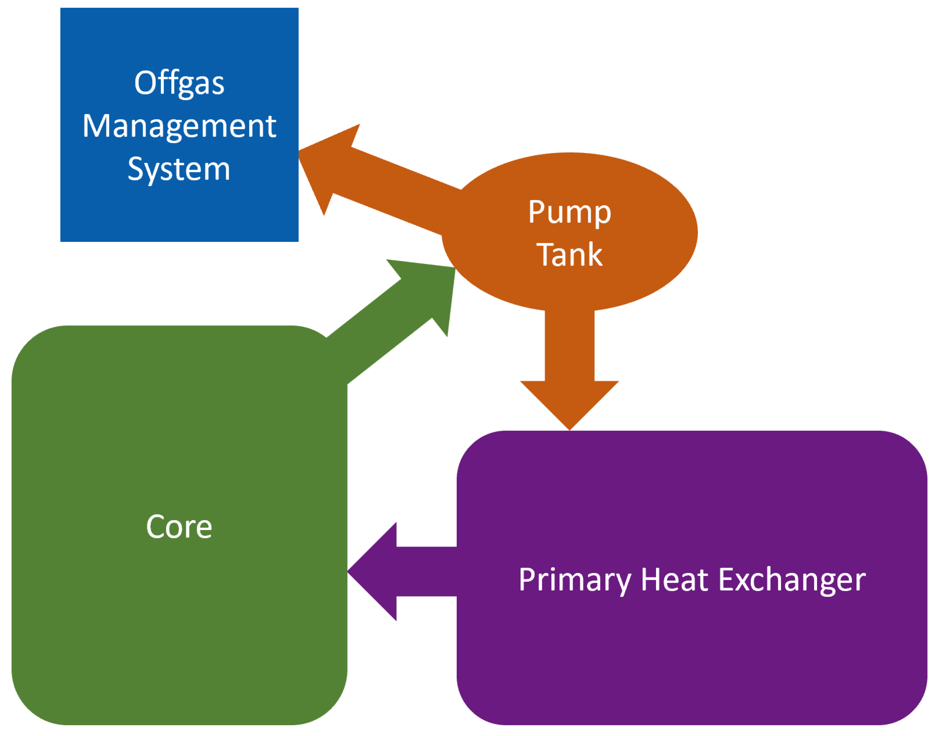
Off-Gas Management and Analysis
3. Process Monitoring Using Off-Gas
3.1. Safeguards Relevance
3.2. System Monitoring
4. Methodology
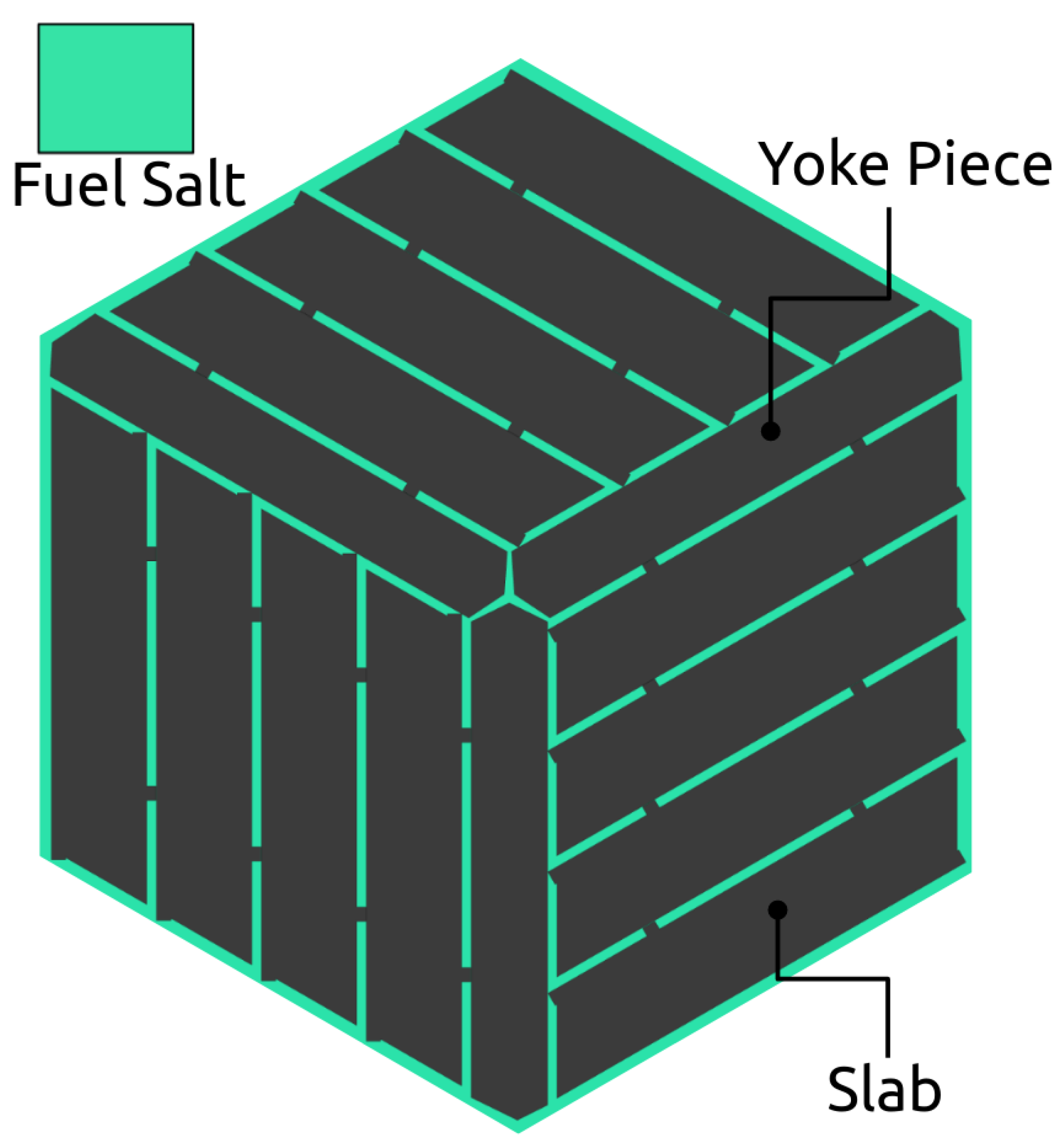
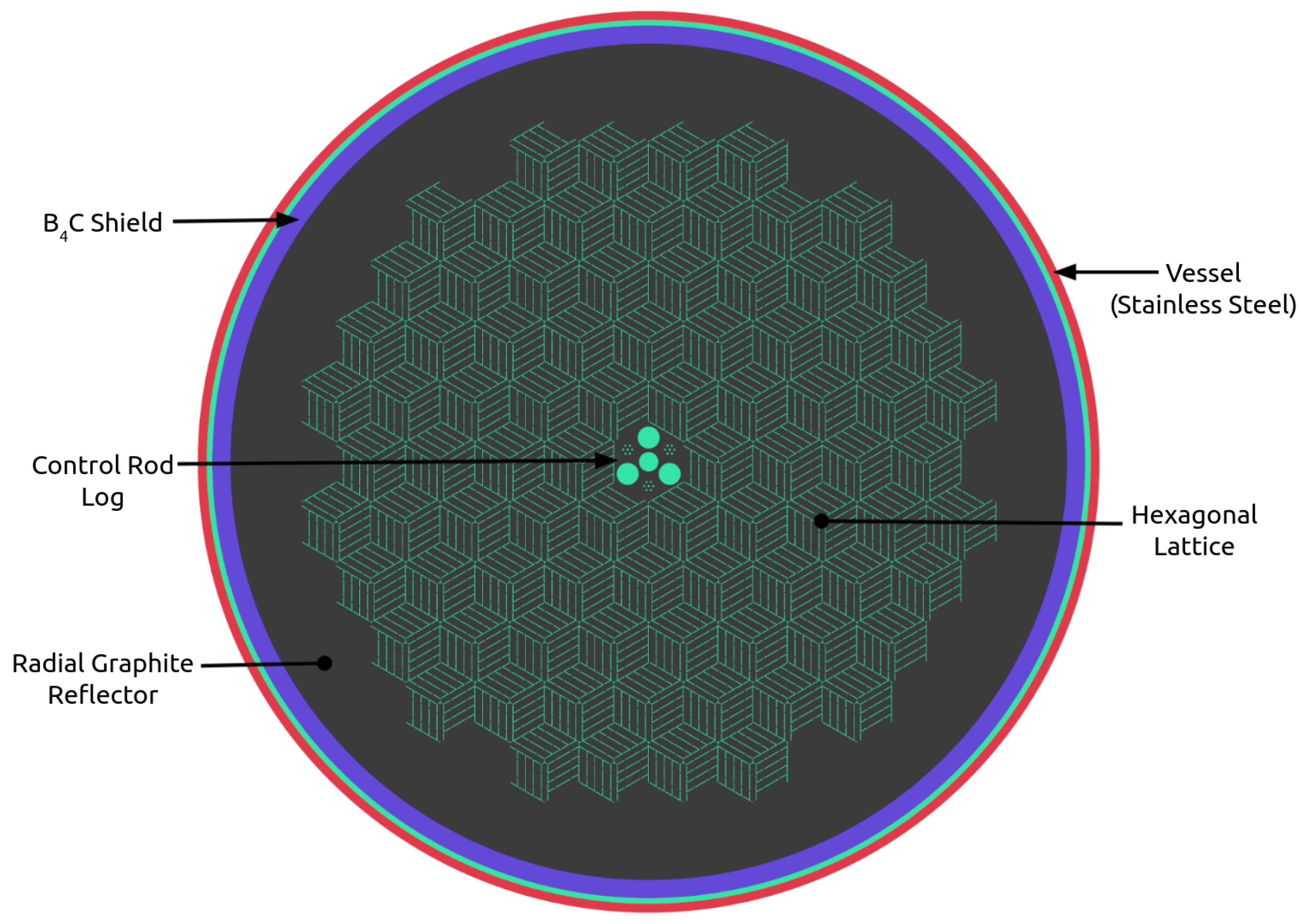
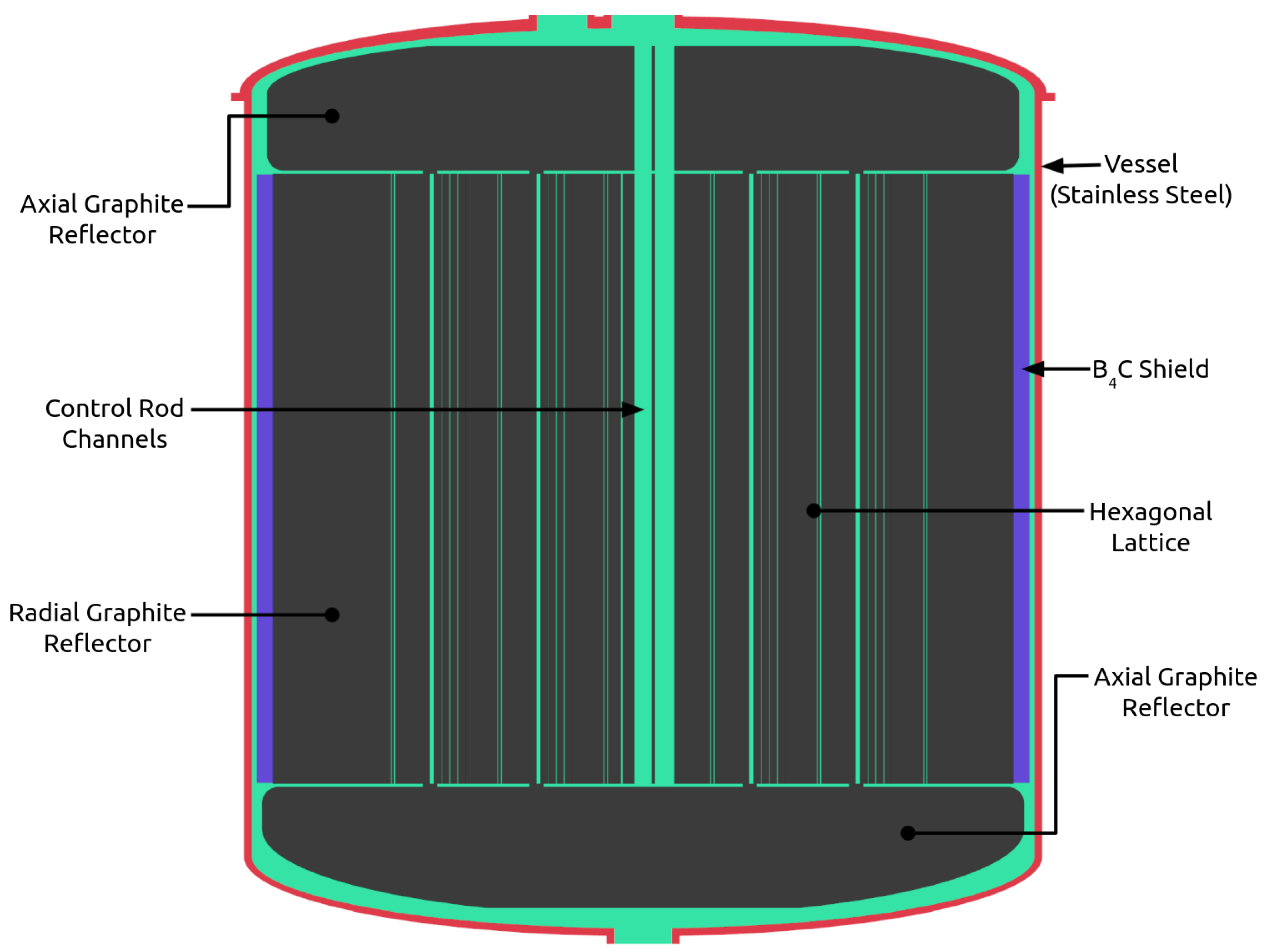
4.1. NERTHUS Neutronics Model
4.2. Fuel Evolution
4.3. Isotopes of Interest
5. Results
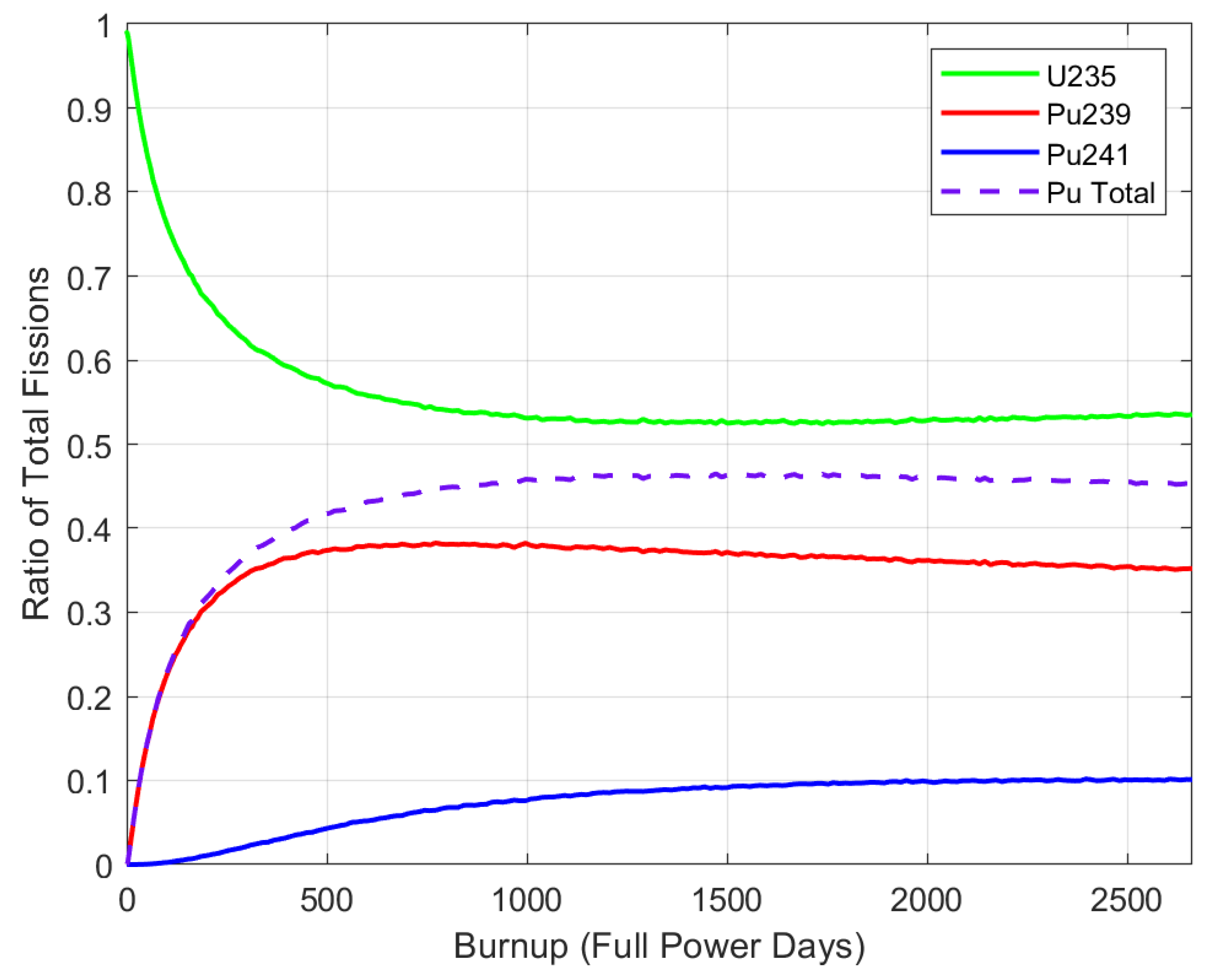
5.1. Fission Participation Ratio
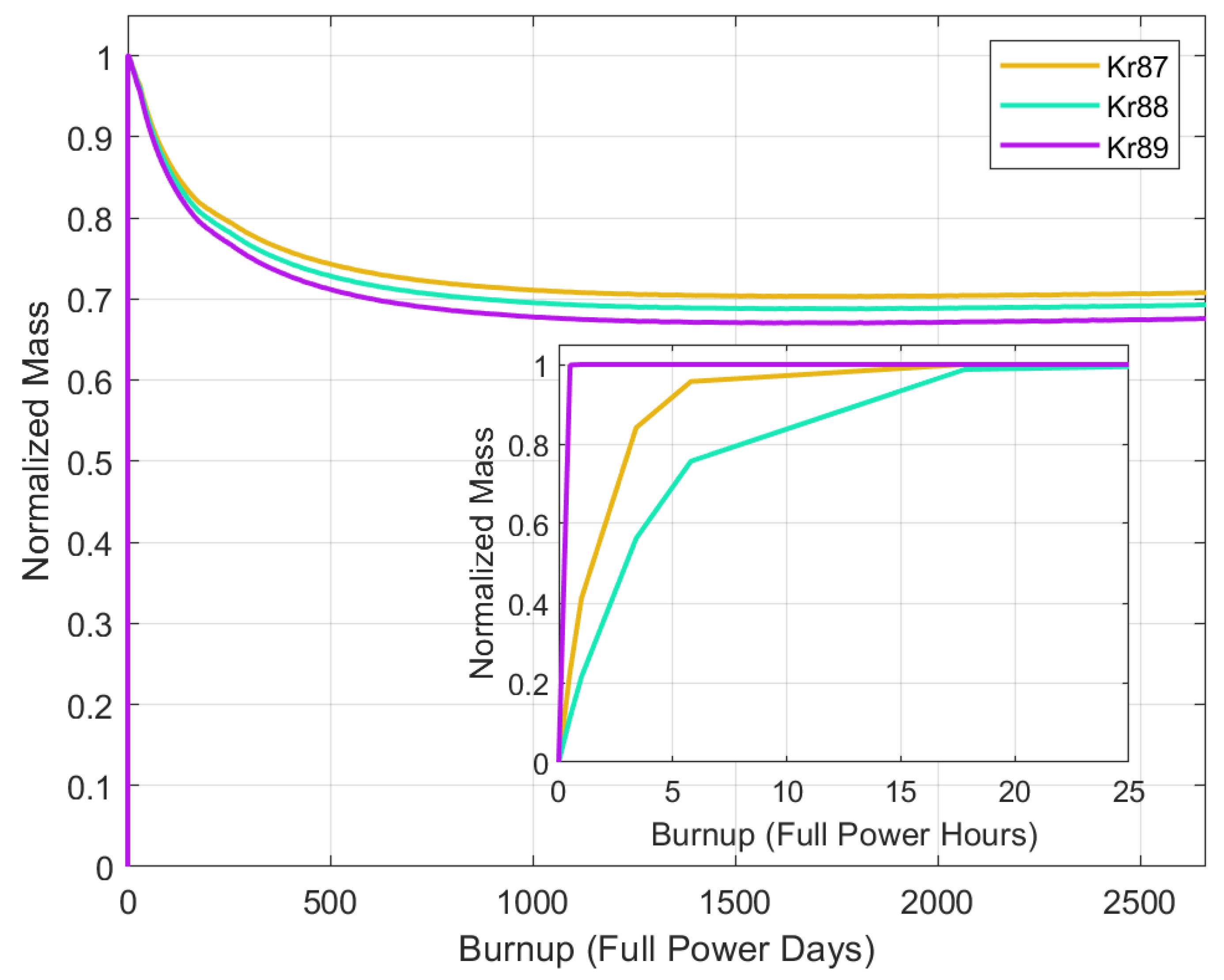
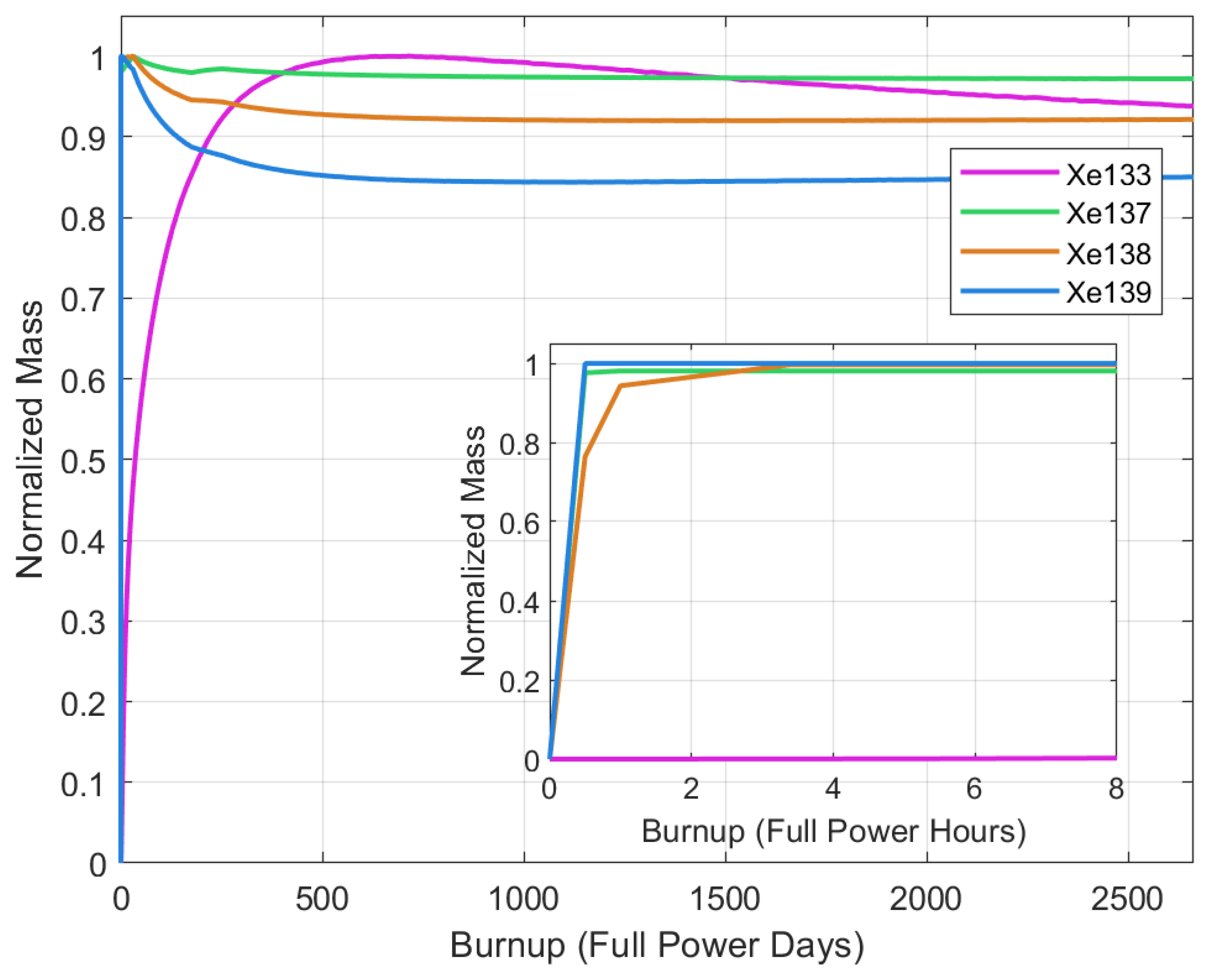
5.2. Mass Buildup
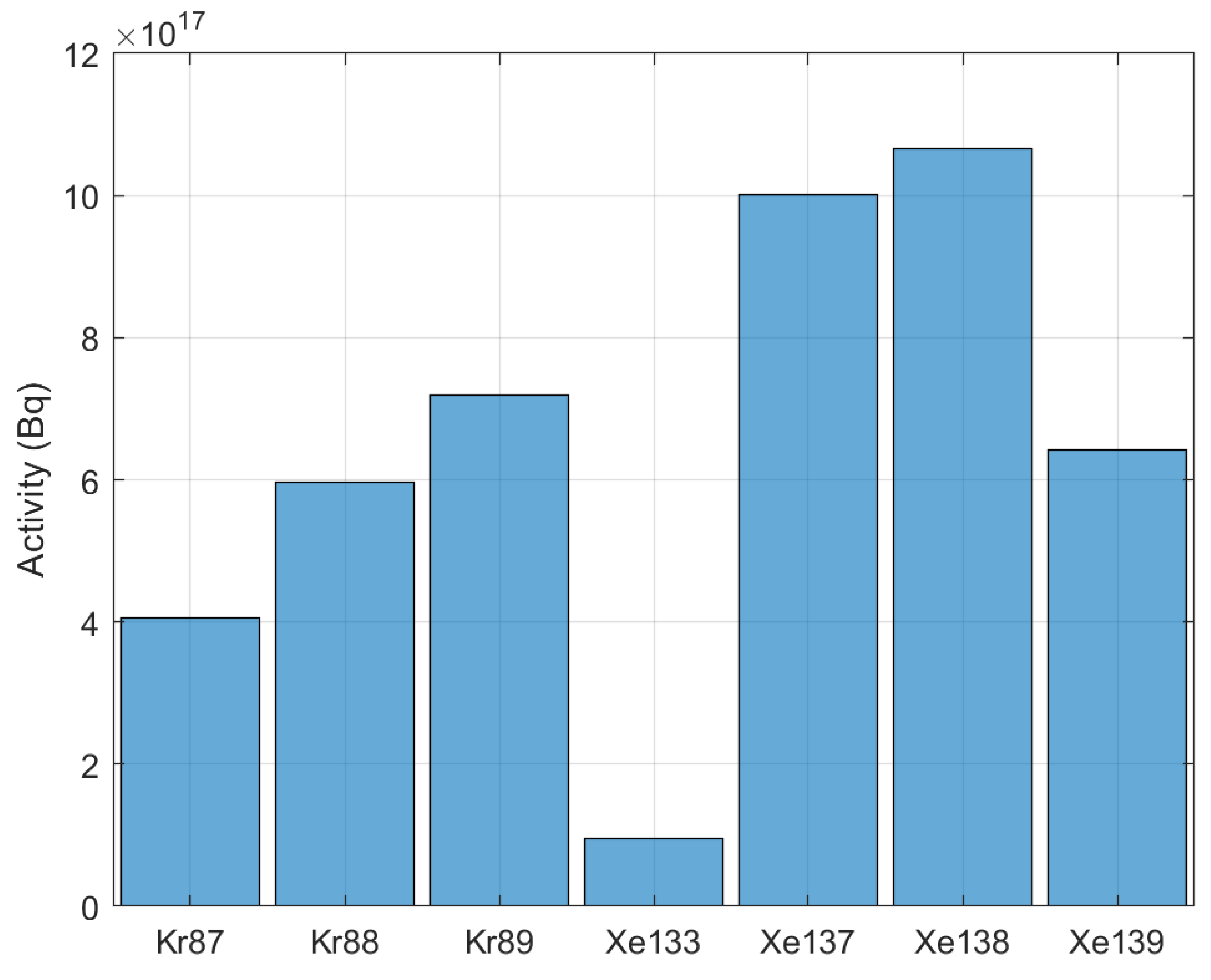
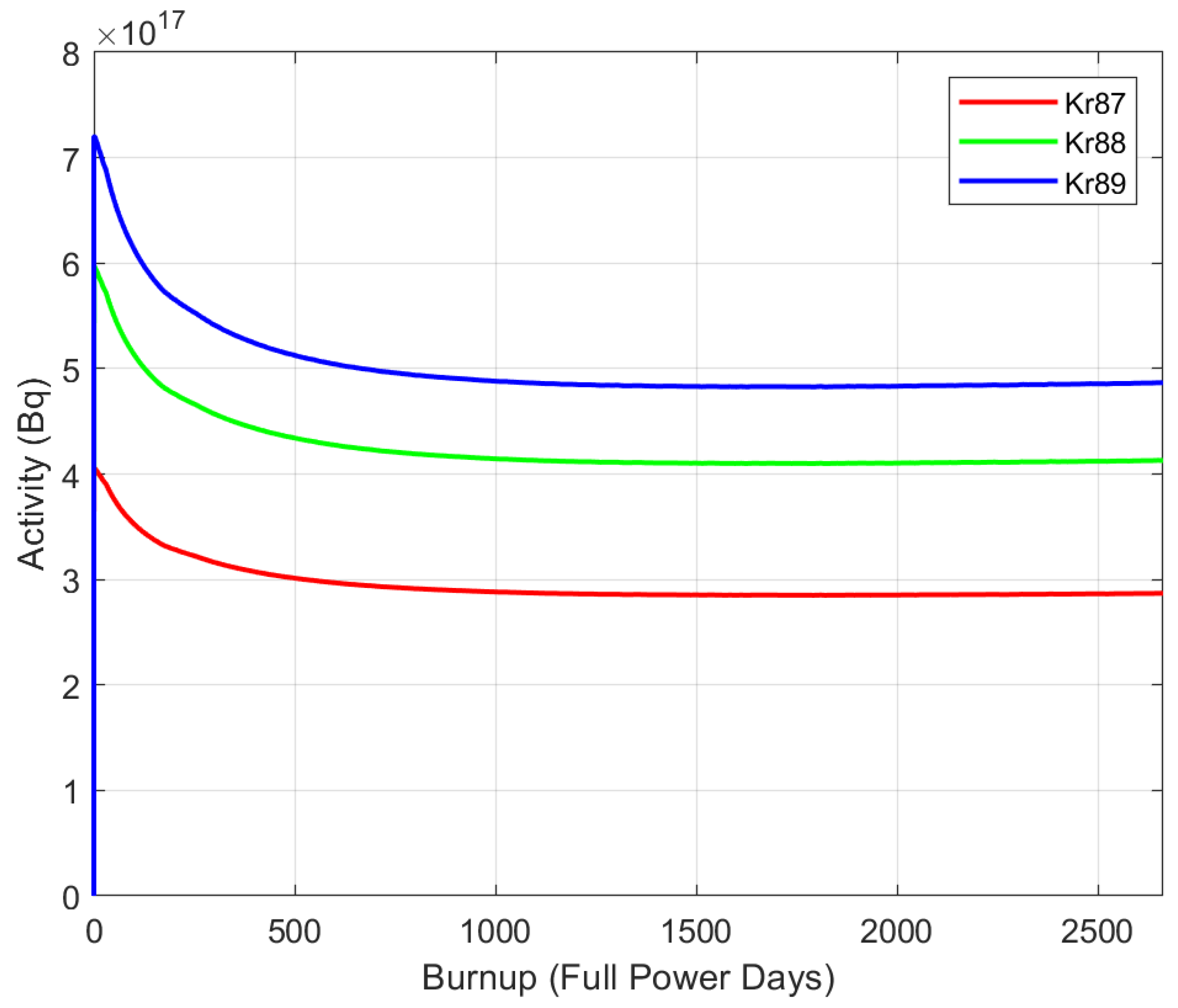
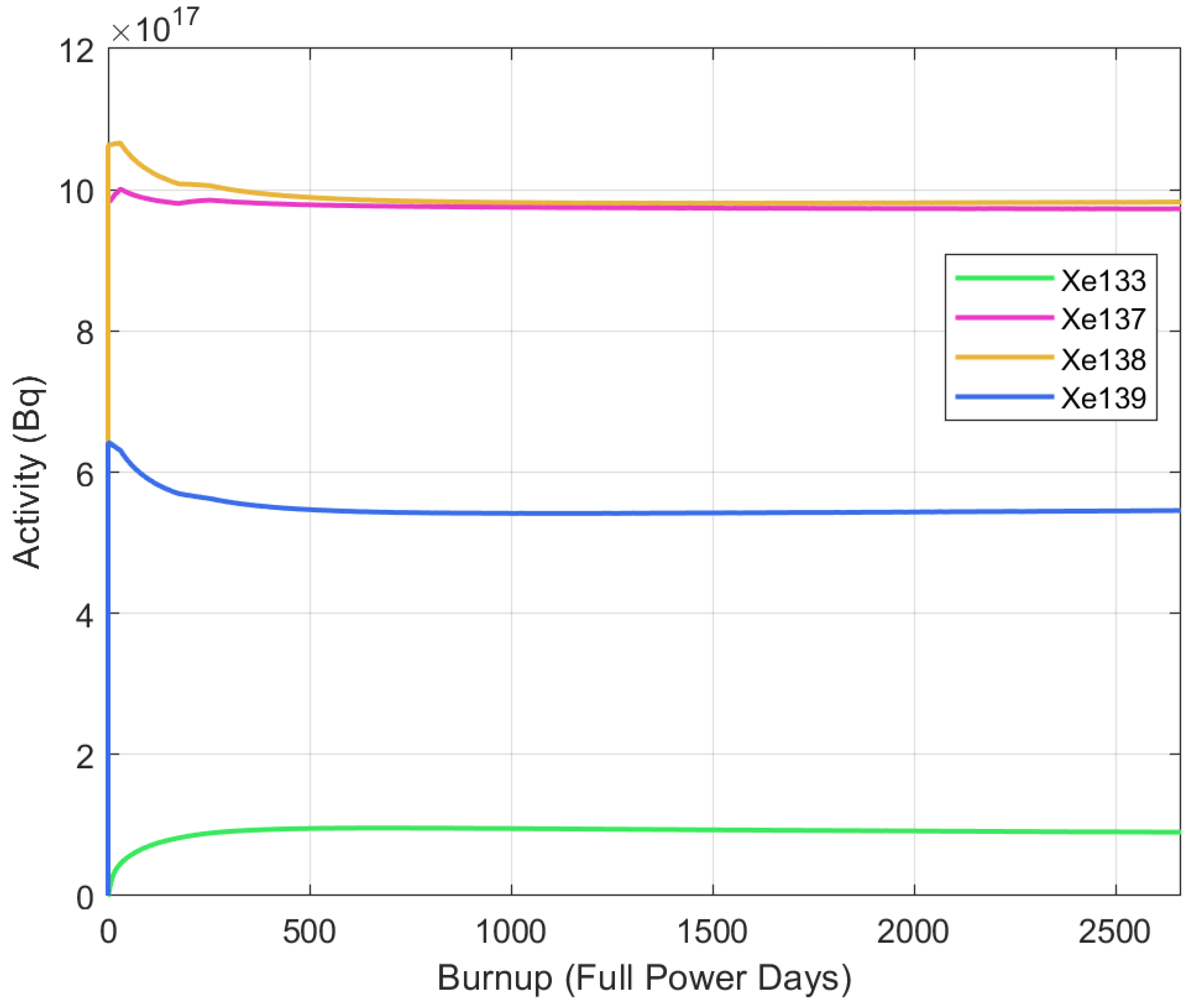
5.3. Activity
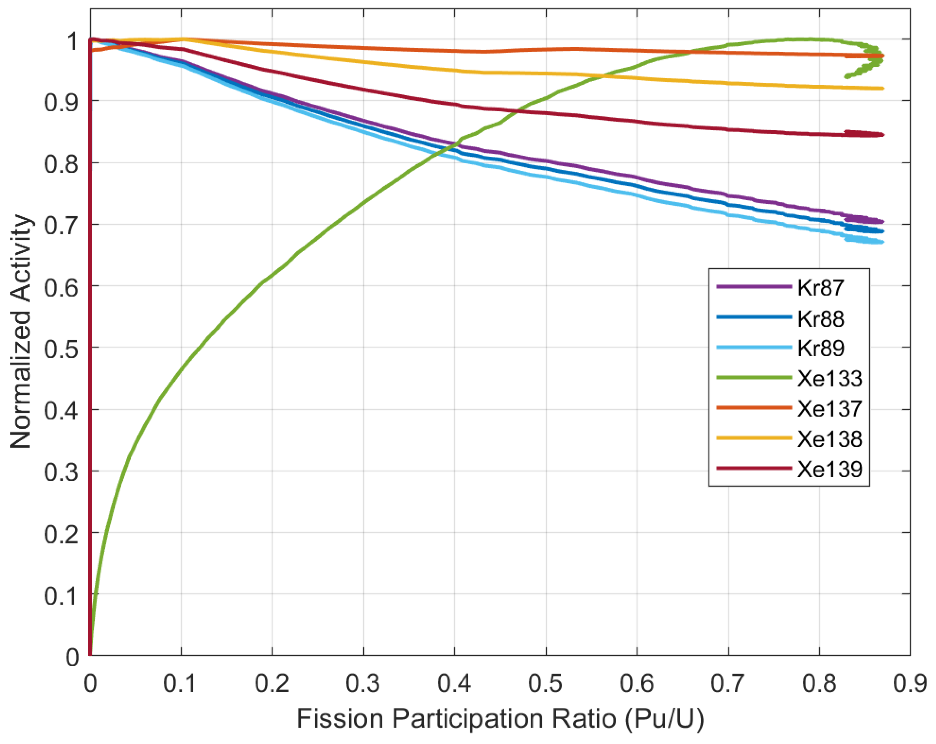
5.4. Activity Relationship to Fission Participation
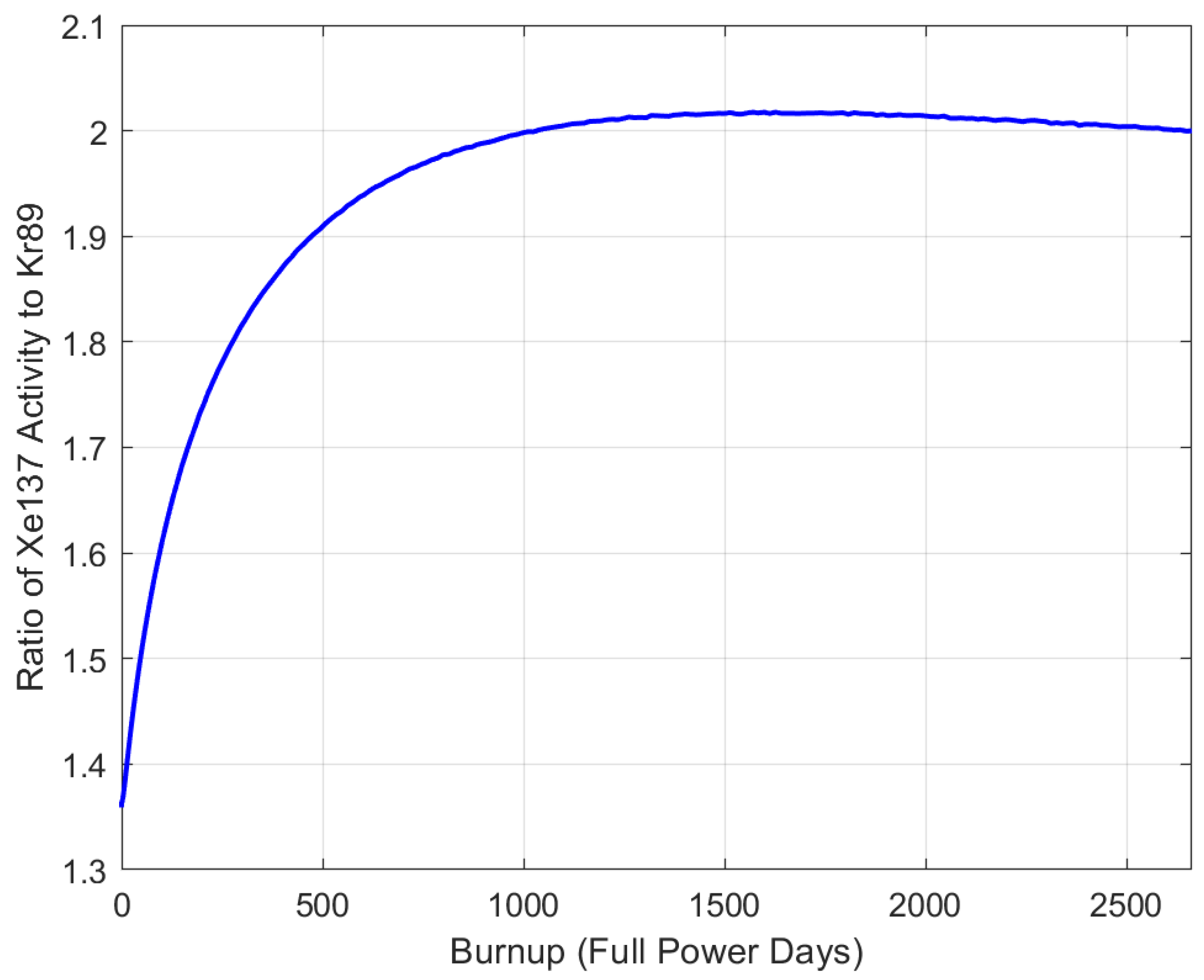
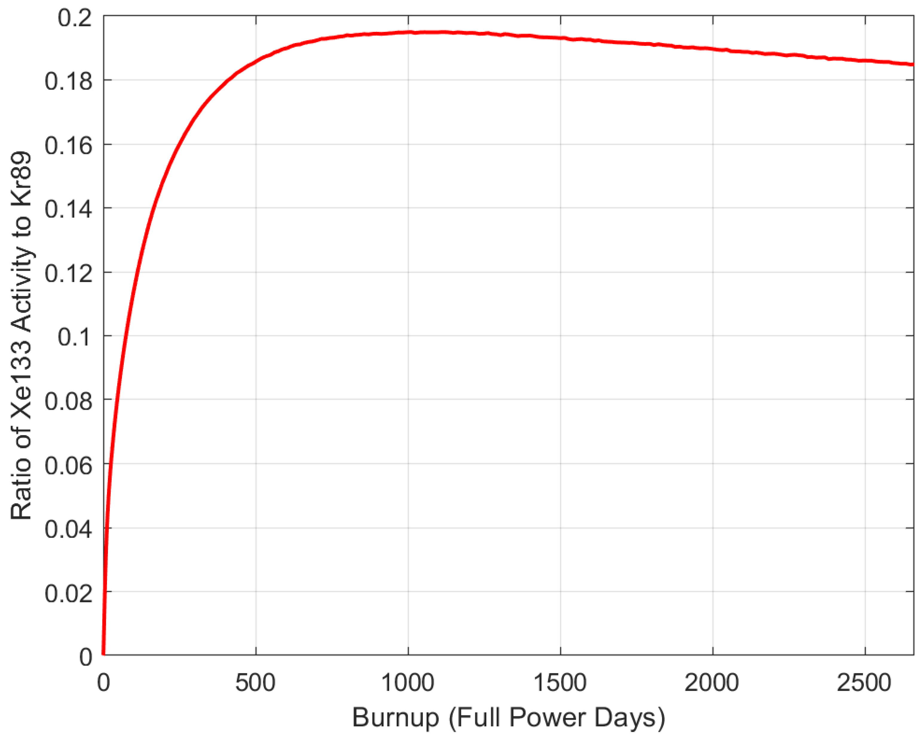
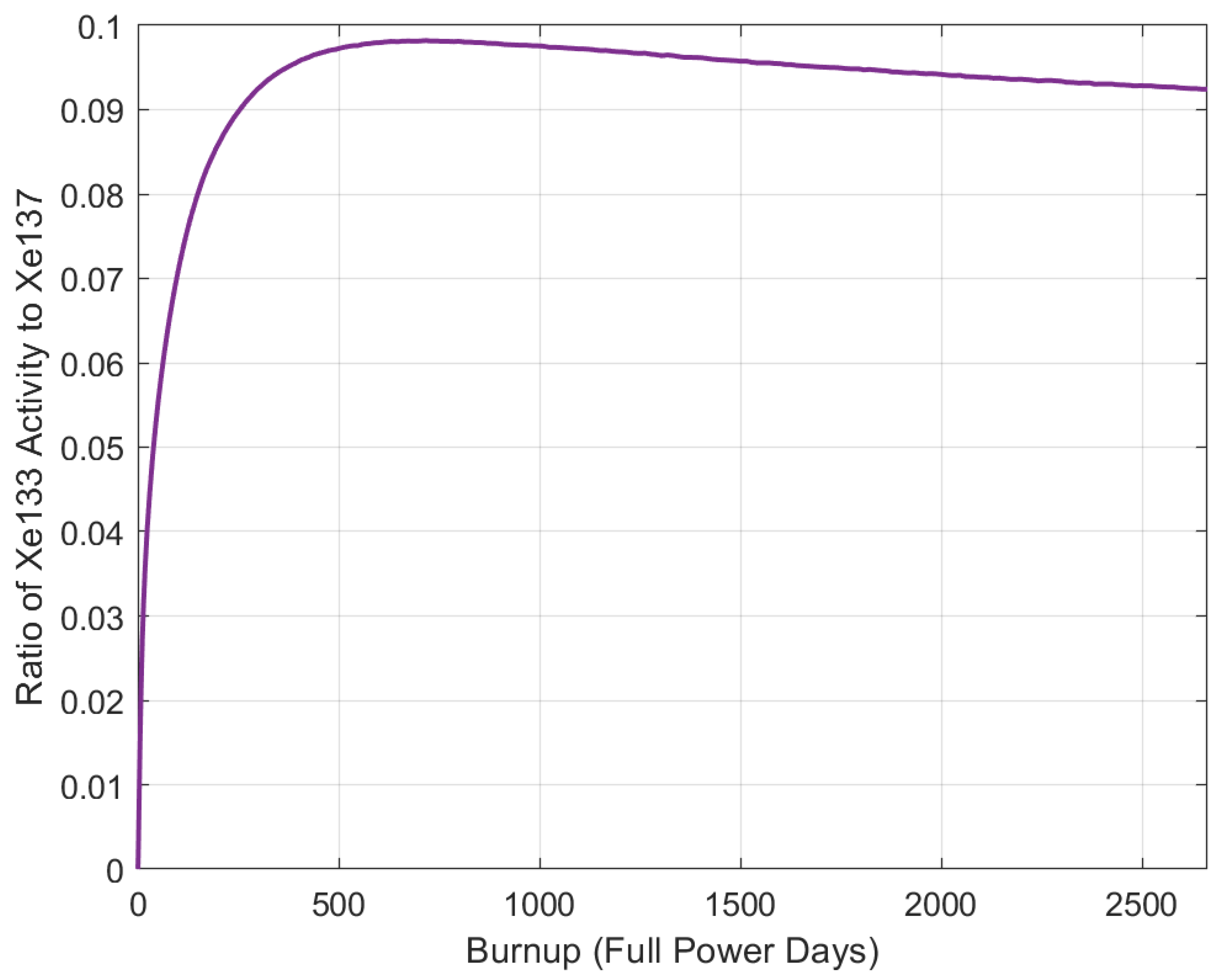
5.5. Isotope Pairs
6. Conclusions
Author Contributions
Funding
Conflicts of Interest
References
- Dunkle, N.; Chvala, O. Safeguards By Design Considerations For Modular Molten Salt Reactors. In Proceedings of the INMM/ESARDA Joint Annual Meeting, INMM, Online, 21–26 August 2021; Available online: https://resources.inmm.org/annual-meeting-proceedings/safeguards-design-considerations-modular-molten-salt-reactors (accessed on 2 May 2023).
- Leppanen, J. Serpent—A Continuous-energy Monte Carlo Reactor Physics Burnup Calculation Code. 2015, Volume 6. Available online: https://usermanual.wiki/Document/Serpentmanual.1526141273/view (accessed on 2 May 2023).
- Wheeler, A.M.; Chvála, O.; Skutnik, S. Signatures of plutonium diversion in Molten Salt Reactor dynamics. Ann. Nucl. Energy 2021, 160, 108370. [Google Scholar] [CrossRef]
- Dunkle, N.J.; Richardson, J.; Pathirana, V.; Wheeler, A.; Chvala, O.; Skutnik, S.E. NERTHUS Thermal Spectrum Molten Salt Reactor Neutronics and Dynamic Model. Nucl. Eng. Des. 2022. Available online: https://papers.ssrn.com/sol3/papers.cfm?abstract_id=4351209 (accessed on 2 May 2023).
- Dunkle, N.; Chvala, O. Effect of Xenon Removal Rate on Load Following in High Power Thermal Spectrum Molten-Salt Reactors (MSRs). Nucl. Eng. Des. 2023, 409, 112329. Available online: https://www.sciencedirect.com/science/article/pii/S0029549323001784 (accessed on 2 May 2023). [CrossRef]
- MacPherson, H.G. The Molten Salt Reactor Adventure. Nucl. Sci. Eng. 1985, 90, 374–380. [Google Scholar] [CrossRef]
- Li, R.; Wang, S.; Rineiski, A.; Zhang, D.; Merle-Lucotte, E. Transient analyses for a molten salt fast reactor with optimized core geometry. Nucl. Eng. Des. 2015, 292, 164–176. [Google Scholar] [CrossRef]
- Mausolff, Z.; DeHart, M.; Goluoglu, S. Design and assessment of a molten chloride fast reactor. Nucl. Eng. Des. 2021, 379, 111181. [Google Scholar] [CrossRef]
- Felmy, H.M.; Clifford, A.J.; Medina, A.S.; Cox, R.M.; Wilson, J.M.; Lines, A.M.; Bryan, S.A. On-Line Monitoring of Gas-Phase Molecular Iodine Using Raman and Fluorescence Spectroscopy Paired with Chemometric Analysis. Environ. Sci. Technol. 2021, 55, 3898–3908. [Google Scholar] [CrossRef] [PubMed]
- Hughey, K.D.; Bradley, A.M.; Felmy, H.M.; Clifford, A.J.; Cox, R.M.; Lines, A.M.; Bryan, S.A.; Johnson, T.J. Quantitative far-infrared band strengths of iodine monochloride (ICl), a molten salt off-gas product. In Chemical, Biological, Radiological, Nuclear, and Explosives (CBRNE) Sensing XXI; Guicheteau, J.A., Howle, C.R., Eds.; International Society for Optics and Photonics, SPIE: Washington, DC, USA, 2020; Volume 11416, p. 114160Q. [Google Scholar] [CrossRef]
- Hughey, K.D.; Bradley, A.M.; Tonkyn, R.G.; Felmy, H.M.; Blake, T.A.; Bryan, S.A.; Johnson, T.J.; Lines, A.M. Absolute Band Intensity of the Iodine Monochloride Fundamental Mode for Infrared Sensing and Quantitative Analysis. J. Phys. Chem. A 2020, 124, 9578–9588. [Google Scholar] [CrossRef] [PubMed]
- Carpenter, M.H.; Koehler, K.; De Castro, K.; Mercer, D.; Weidenbenner, S.; Vo, D.; Sagadevan, A.; Henzlova, D.; Menlove, H.; Croce, M.; et al. Experimental validation of nda capabilities for msr safeguards: First results. In Proceedings of the INMM & ESARDA Joint Virtual Annual Meeting, Online, 21–26 August 2021. [Google Scholar]
- Graham, A.M.; Taylor, Z.; Collins, B.S.; Salko, R.K.; Poschmann, M. Multiphysics Coupling Methods for Molten Salt Reactor Modeling and Simulation in VERA. Nucl. Sci. Eng. 2021, 195, 1065–1086. [Google Scholar] [CrossRef]
- Nakhleh, C.W.; Stanbro, W.D.; Hand, L.N.; Perry, R.T., Jr.; Wilson, W.B.; Fearey, B.L. Noble-gas atmospheric monitoring for international safeguards at reprocessing facilities. Sci. Glob. Secur. 1997, 6, 357–379. [Google Scholar] [CrossRef]
- Compere, E.L.; Kirslis, S.S.; Bohlmann, E.G.; Blankenship, F.F.; Grimes, W.R. Fission product behavior in the Molten Salt Reactor Experiment; Oak Ridge National Lab: Oak Ridge, TN, USA, 1975; p. 10. Available online: https://www.osti.gov/biblio/4077644 (accessed on 2 May 2023).
- Baes, C.F., Jr. The chemistry and thermodynamics of molten salt reactor fuels. J. Nucl. Mater. 1974, 51, 149–162. [Google Scholar] [CrossRef]
- Riley, B.J.; Mcfarlane, J.; DelCul, G.; Vienna, J.D.; Contescu, C.I.; Hay, L.M.; Savino, A.V.; Adkins, H.E. Identification of Potential Waste Processing and Waste Form Options for Molten Salt Reactors; Oak Ridge National Lab: Oak Ridge, TN, USA, 2018; p. 8. [CrossRef]
- Andrews, H.B.; McFarlane, J.; Chapel, A.S.; Ezell, N.D.B.; Holcomb, D.E.; de Wet, D.; Greenwood, M.S.; Myhre, K.G.; Bryan, S.A.; Lines, A.; et al. Review of molten salt reactor off-gas management considerations. Nucl. Eng. Des. 2021, 385, 111529. [Google Scholar] [CrossRef]
- McFarlane, J.; Riley, B.; Holcomb, D.E.; Lines, A.; Andrews, H.B.; Bryan, S.A.; Chapel, A.S.; Ezell, N.D.B.; Felmy, H.M.; Greenwood, M.S.; et al. Molten Salt Reactor Engineering Study for Off-Gas Management; Oak Ridge National Laboratory: Oak Ridge, TN, USA, 2020; p. 8. [CrossRef]
- Robertson, R.C. MSRE Design & Operations Report Part 1 Description of Reactor Design; ORNL-TM-728; Oak Ridge National Laboratory: Oak Ridge, TN, USA, 1965; p. 1. Available online: http://moltensalt.org/references/static/downloads/pdf/ORNL-TM-0728.pdf (accessed on 2 May 2023).
- Robertson, R.C. Conceptual Design Study of a Single-Fluid Molten-Salt Breeder Reactor; Oak Ridge National Lab: Oak Ridge, TN, USA, 1971; p. 1. [CrossRef]
- Riley, B.J.; McFarlane, J.; DelCul, G.D.; Vienna, J.D.; Contescu, C.I.; Forsberg, C.W. Molten Salt Reactor Waste and Effluent Management Strategies: A review. Nucl. Eng. Des. 2019, 345, 94–109. [Google Scholar] [CrossRef]
- Banerjee, D.; Cairns, A.J.; Liu, J.; Motkuri, R.K.; Nune, S.K.; Fernandez, C.A.; Krishna, P.; Strachan, D.M.; Thallapally, P.K. Potential of Metal–Organic Frameworks for Separation of Xenon and Krypton. Accounts Chem. Res. 2015, 48, 211–219. [Google Scholar] [CrossRef] [PubMed]
- ORNL. The Molten-Salt Reactor Experiment; United States Atomic Energy Commission: Washington, DC, USA, 1969. Available online: https://youtu.be/tyDbq5HRs0o (accessed on 2 May 2023).
- IAEA. On-Line Monitoring for Improving Performance of Nuclear Power Plants Part 2: Process and Component Condition Monitoring and Diagnostics; Number NP-T-1.2 in Nuclear Energy Series; International Atomic Energy Agency: Vienna, Austria, 2008; ISBN 978-92-0-101208-1. Available online: https://www.iaea.org/publications/7908/on-line-monitoring-for-improving-performance-of-nuclear-power-plants-part-2-process-and-component-condition-monitoring-and-diagnostics (accessed on 2 May 2023).
- Ehinger, M.H.; Pomeroy, G.D.; Budlong-Sylvester, K.W. Process Monitoring for Nuclear Safeguards. In Nuclear Fuel Cycle and Fuel Materials (S11); ORNL, INIS: Oak Ridge, TN, USA, 2009. Available online: https://inis.iaea.org/search/searchsinglerecord.aspx?recordsFor=SingleRecord&RN=43126277 (accessed on 2 May 2023).
- Lines, A.M.; Hall, G.B.; Asmussen, S.; Allred, J.; Sinkov, S.; Heller, F.; Gallagher, N.; Lumetta, G.L.; Bryan, S.A. Sensor Fusion: Comprehensive Real-Time, On-Line Monitoring for Process Control via Visible, Near-Infrared, and Raman Spectroscopy. ACS Sens. 2020, 5, 2467–2475. [Google Scholar] [CrossRef] [PubMed]
- Kovacic, D.N.; Worrall, A.; Worrall, L.G.; Flanagan, G.F.; Holcomb, D.E.; Bari, R.; Cheng, L.; Farley, D.; Sternat, M. Safeguards Challenges for Molten Salt Reactors; USDOE: Washington, DC, USA, 2018; p. 8. Available online: https://www.osti.gov/biblio/1474868 (accessed on 2 May 2023).
- Phillips, J.R. Passive Nondestructive Assay of Nuclear Materials—Irradiated Fuel Measurements. 1991; p. 3. Available online: https://www.lanl.gov/org/ddste/aldgs/sst-training/_assets/docs/PANDA/Iradiated%20Fuel%20Measurements%20Ch.%2018%20p.%20529-562.pdf (accessed on 2 May 2023).
- Beneš, O.; Capelli, E.; Morelová, N.; Colle, J.Y.; Tosolin, A.; Wiss, T.; Cremer, B.; Konings, R.J.M. Cesium and iodine release from fluoride-based molten salt reactor fuel. Phys. Chem. Chem. Phys. 2021, 23, 9512–9523. [Google Scholar] [CrossRef] [PubMed]
- Geng, J.; Zhao, Z.; Cheng, Z.; Li, W.; Dou, Q.; Li, Q. Activity measurement of iodine fission products in 2lif-bef2 salt and its application in redox potential surveillance for a thorium molten salt reactor. Inorg. Chem. 2022, 61, 7406–7413. [Google Scholar] [CrossRef] [PubMed]
- ThorCon USA Inc. Thorcon Documents. 2021. Available online: https://thorconpower.com/documents (accessed on 2 May 2023).
- Wheeler, A.M.; Chvála, O. Molten Salt Reactor Sourdough Refueling and Waste Management Strategy. J. Nucl. Eng. 2021, 2, 471–483. [Google Scholar] [CrossRef]
- Chadwick, M.B.; Obložinský, P.; Herman, M.; Greene, N.M.; McKnight, R.D.; Smith, D.L.; Young, P.G.; MacFarlane, R.E.; Hale, G.M.; Frankle, S.C.; et al. ENDF/B-VII. 0: Next generation evaluated nuclear data library for nuclear science and technology. Nucl. Data Sheets 2006, 107, 2931–3060. [Google Scholar] [CrossRef]
- Coastal Chemical Co. LLC. Hitec® Heat Transfer Salt. Available online: http://stoppingclimatechange.com/MSR%20-%20HITEC%20Heat%20Transfer%20Salt.pdf (accessed on 2 May 2023).
- Gehin, J.C.; Powers, J.J. Liquid fuel molten salt reactors for thorium utilization. Nucl. Technol. 2016, 194, 152–161. Available online: https://www.osti.gov/pages/servlets/purl/1254086 (accessed on 2 May 2023). [CrossRef]
- England, T.R.; Rider, B.F. Evaluation and Compilation of Fission Product Yields; Los Alamos National Lab: Los Alamos, NM, USA, 1994. Available online: https://www-nds.iaea.org/endf349/ (accessed on 2 May 2023).


| Thermal Power | 557 MW |
| Avg Core Inlet Temp | 617 C |
| Avg Core Outlet Temp | 682 C |
| Fuel | Uranium |
| Uranium Enrichment | 2.09% |
| Moderator | Graphite |
| Primary Fluid | LiF-BeF-ZrF-UF |
| Secondary Fluid | LiF-BeF |
| Tertiary Fluid | Hitec Salt [35] |
| Core Residency Time | 15 s |
| PHX Residency Time | 11.6 s |
| Out-of-Core Total Loop Time | 14.6 s |
| Q | U | Pu | Pu | ||||
|---|---|---|---|---|---|---|---|
| Isotope | Half-Life | (MeV) | Yield | Yield | Ratio to U | Yield | Ratio to U |
| Kr | 76.30 m | 3.888 | 0.02558 | 0.00989 | 0.3866 | 0.00751 | 0.2936 |
| Kr | 169.5 m | 2.918 | 0.03553 | 0.01272 | 0.3580 | 0.00976 | 0.2747 |
| Kr | 3.150 m | 5.177 | 0.04511 | 0.01453 | 0.3221 | 0.01148 | 0.2545 |
| Xe | 5.280 d | 0.427 | 0.06700 | 0.07016 | 1.0472 | 0.06729 | 1.0043 |
| Xe | 3.818 m | 4.162 | 0.06129 | 0.06010 | 0.980 | 0.06558 | 1.0700 |
| Xe | 14.14 m | 2.915 | 0.06297 | 0.05171 | 0.8212 | 0.06258 | 0.9938 |
| Xe | 39.68 s | 5.057 | 0.05039 | 0.03086 | 0.6124 | 0.04921 | 0.9766 |
| Isotope | Maximum Mass (g) |
|---|---|
| Kr | 0.3864 |
| Kr | 1.2833 |
| Kr | 0.0290 |
| Xe | 13.8307 |
| Xe | 0.0752 |
| Xe | 0.2977 |
| Xe | 0.0085 |
Disclaimer/Publisher’s Note: The statements, opinions and data contained in all publications are solely those of the individual author(s) and contributor(s) and not of MDPI and/or the editor(s). MDPI and/or the editor(s) disclaim responsibility for any injury to people or property resulting from any ideas, methods, instructions or products referred to in the content. |
© 2023 by the authors. Licensee MDPI, Basel, Switzerland. This article is an open access article distributed under the terms and conditions of the Creative Commons Attribution (CC BY) license (https://creativecommons.org/licenses/by/4.0/).
Share and Cite
Dunkle, N.; Wheeler, A.; Richardson, J.; Bogetic, S.; Chvala, O.; Skutnik, S.E. Plutonium Signatures in Molten-Salt Reactor Off-Gas Tank and Safeguards Considerations. J. Nucl. Eng. 2023, 4, 391-411. https://doi.org/10.3390/jne4020028
Dunkle N, Wheeler A, Richardson J, Bogetic S, Chvala O, Skutnik SE. Plutonium Signatures in Molten-Salt Reactor Off-Gas Tank and Safeguards Considerations. Journal of Nuclear Engineering. 2023; 4(2):391-411. https://doi.org/10.3390/jne4020028
Chicago/Turabian StyleDunkle, Nicholas, Alex Wheeler, Jarod Richardson, Sandra Bogetic, Ondrej Chvala, and Steven E. Skutnik. 2023. "Plutonium Signatures in Molten-Salt Reactor Off-Gas Tank and Safeguards Considerations" Journal of Nuclear Engineering 4, no. 2: 391-411. https://doi.org/10.3390/jne4020028