Communication

Application of Np–Am Mixture in Production of 238Pu in a VVER-1000 Reactor and the Reactivity Effect Caused by Loss-of-Coolant Accident in the Central Np–Am Fuel Assembly

by
Anatoly N. Shmelev
,
Nikolay I. Geraskin
,
Vladimir A. Apse
,
Vasily B. Glebov
*,
Evgeny G. Kulikov
and
Andrey A. Krasnoborodko
Institute of Nuclear Physics and Engineering, National Research Nuclear University MEPhI, Kashirskoe Shosse 31, Moscow 115409, Russia
*
Author to whom correspondence should be addressed.
J. Nucl. Eng. 2023, 4(2), 412-420; https://doi.org/10.3390/jne4020029
Submission received: 3 March 2023 / Revised: 16 May 2023 / Accepted: 19 May 2023 / Published: 1 June 2023

Abstract

:
This paper presents the results obtained from numerical evaluations for the possibility of large-scale 238Pu production in the light-water VVER-1000 reactor and the reactivity effect caused by the loss-of-coolant accident in the central fuel assembly of the reactor core. This fuel assembly containing the Np–Am-component of minor actinides was placed in the center of the reactor core and intended for intense production of 238Pu. Optimal conditions were found for large-scale production of plutonium with an isotope composition suitable for application in radioisotope thermoelectric generators. The reactivity effect from the loss-of-coolant accident in the central Np–Am fuel assembly was evaluated, and the perturbation theory was used to determine the contributions of some neutron processes (leakage, absorption, and moderation) to the total variation of the effective neutron multiplication factor.

1. Introduction

Plutonium isotope 238Pu is characterized by a series of specific properties [1] that make it a valuable source of thermal and electrical energy in radioisotope thermoelectric generators (RITEG). The main subject of the present paper is a feasibility study for large-scale plutonium production [2] with an isotope composition suitable for RITEG [3] of spacecrafts in the light-water power reactor VVER-1000. In Russia, the production of 238Pu-based RITEG for navigation services was completely halted. However, 238Pu-based RITEG represents a significant component of cosmic programs for further exploration of outer space. Production Association (PA) “Mayak” is a leading Russian producer of 238Pu [4]. Some publications (for instance, references [5,6]) are devoted to a thorough analysis of possibilities for 238Pu production in US research reactors. The thermal neutron spectra in the research reactors ATR (Idaho National Laboratory [5]) and HFIR (Oak Ridge National Laboratory [6]) are able to intensify the fruitful 237Np(n,γ)238Pu reaction and, at the same time, suppress the undesirable 237Np(n,2n)236Pu reaction, which can only be initiated by fast neutrons with energies above 6 MeV.
In our previous article [7], the challenge of large-scale production of plutonium was addressed with the application of neptunium dioxide NpO2 as a starting material. This paper analyzes the possibility of extended inclusion of minor actinides in the starting material. Fractions of neptunium–americium from the composition of transuranic radioactive wastes (TRUW) were used as a starting material. A number of works [8,9] have been devoted to the analysis of technologies for the extraction of MA from VVER spent nuclear fuel. In the present paper, the following values were taken as TRUW generation rate in light-water VVER-type reactors [9]:
237Np − 20.4 kg/GWe∙year; 241Am − 1.3 kg/GWe∙year; 243Am − 2.5 kg/GWe∙year.
It should be mentioned that a significant number of works [10,11,12] are devoted to the neutron-induced incineration of MA as a main component of TRUW. In the present paper, neutron irradiation of the Np–Am-fraction makes it possible to generate a fruitful material (plutonium) and, at the same time, to exterminate some part of TRUW. The irradiation device (ID) that was placed in the center of the reactor core represented the fuel assembly (FA), surrounded by six special assemblies. In the central fuel assembly of the ID, conventional uranium dioxide fuel was replaced by a mixture of neptunium and americium dioxides (Figure 1).
As it is known, MA are relatively weaker neutron absorbers (for instance, in comparison with 235U) in the thermal and intermediate energy ranges, while in the high-energy range, MA are well-fissile isotopes [13]. The curves presented in Figure 2 demonstrate a remarkable growth in the effective quantity of secondary neutrons per fission νeff for neptunium and americium isotopes at incident neutron energies above 100 keV. In connection with the circumstances mentioned above, the loss-of-coolant accident in the central Np–Am-FA can shift the neutron spectrum towards the higher energy range and produce a positive reactivity effect caused by the better neutron-multiplying properties and the weaker neutron absorption by MA isotopes.
The perturbation theory was used in the numerical studies to evaluate the contributions given by some neutron processes to the total reactivity effect caused by the loss-of-coolant accident in the Np–Am-FA that was placed in the center of the VVER-1000 reactor core.

2. Materials and Methods

2.1. Capabilities of Plutonium Production in Np–Am-FA

This paper presents numerical evaluations of scales for the production of RITEG-suitable plutonium (above 80% 
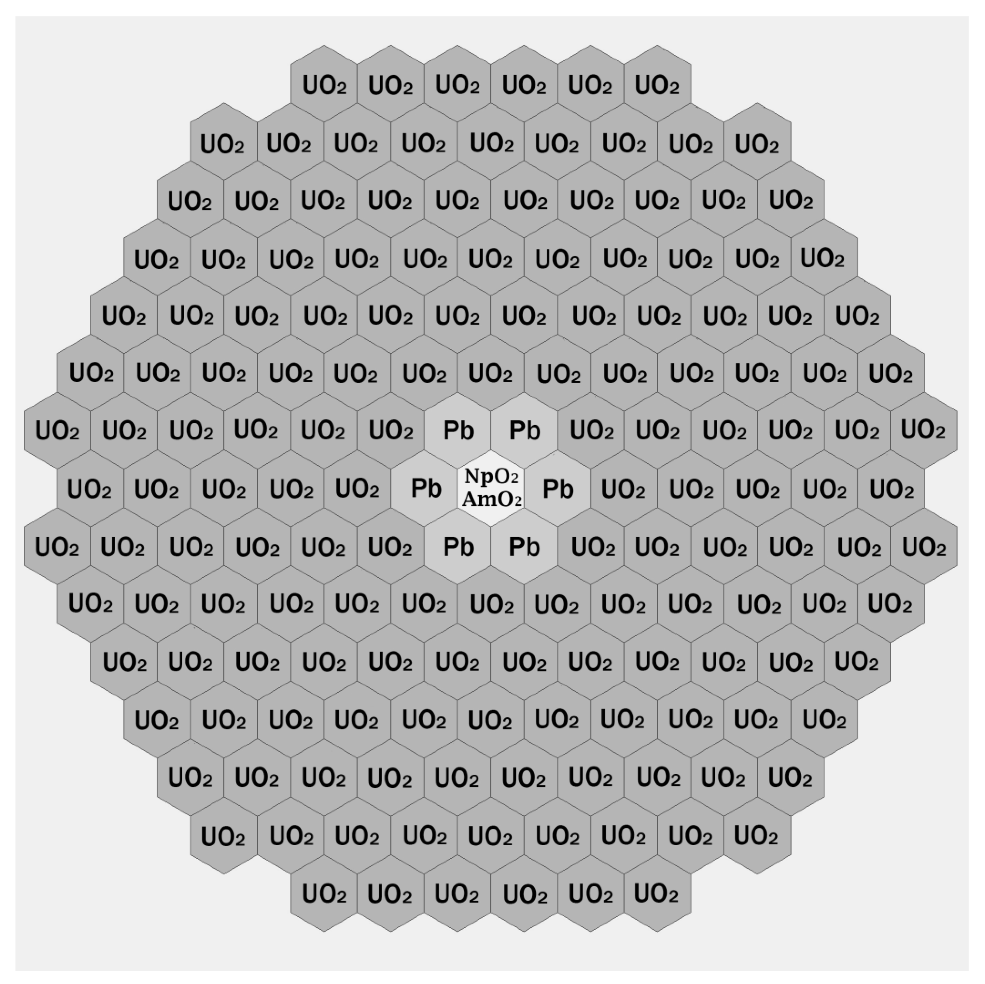
238Pu and below 2 ppm 236Pu) in the Np–Am-FA of the VVER-1000 reactor. The irradiation device consists of seven fuel assemblies. The central FA is a standard VVER-1000 assembly where enriched uranium dioxide was replaced by neptunium–americium dioxide NpO2–AmO2 (Figure 3). Np–Am-O2-rods consisted of only neptunium–americium dioxide in Zr–Nb cladding without any additions. The composition of six surrounding FAs was chosen in such a way as to intensify the 238Pu production rate in the central FA. The design of the irradiated assemblies with NpO2 and a Np–Am-O2-mixture was assumed to be the same (see Figure 3).
There are many commercial and exploratory codes that were used to analyze neutron-physical processes in the VVER-1000 reactor. For instance, the software packages KASKAD (product of the National Research Center—Kurchatov Institute [14]) and SERPENT [15] were used. Nevertheless, for these exploratory studies, the diffusion code TIME26 was chosen because it is the most accessible and long-term used by the authors of this work. The computer code TIME26 is able to determine the time-dependent evolution of neutron flux and fuel isotope composition. The initial isotope composition of the reactor core was used to solve the neutron diffusion equations and compute the space-energy distribution of neutron flux. The obtained distribution of neutron flux was used to solve the fuel burn-up equations for the determination of new fuel isotope composition after a certain time interval of reactor operation. By repeating these step-by-step computations, the code was able to find the time dependency of the fuel isotope composition, including the amount of plutonium and its isotope composition. The main neutron-physical parameters and time dependency of the fuel isotope composition were determined for the cylindrical model of the VVER-1000 reactor core in a 26-group diffusion approximation. Micro cross-sections of neutron reactions were taken and processed from the evaluated nuclear data file ABBN-78 [16,17].
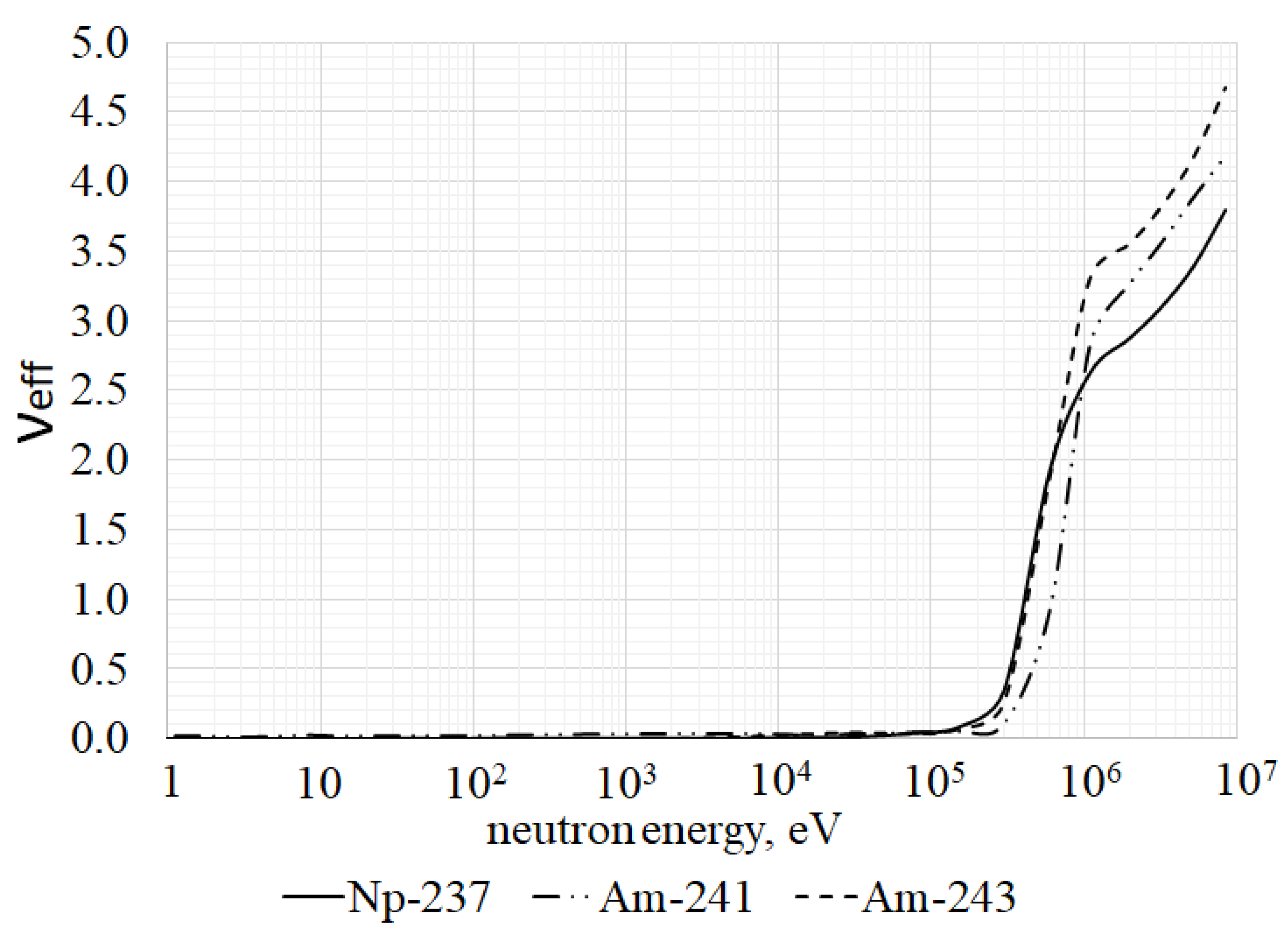
Two isotope compositions of the Np–Am-fraction were used in the numerical evaluations. The first composition was 100% 237Np, while the second one was a mixture of neptunium and americium isotopes (84.3% 237Np, 5.4% 241Am, and 10.3% 243Am). The second variant corresponded to the isotope composition of MA extracted from spent fuel in light-water VVER-type reactors.
The best conditions for the production of RITEG-suitable plutonium were provided by relatively wide lattices of Np–Am fuel elements with an encirclement of the central Np–Am-FA by six fuel assemblies filled up with natural lead or radiogenic lead (100% 208Pb). The larger volume fraction of coolant in the wider lattice of the Np–Am fuel elements can soften the neutron spectrum and, as a consequence, promote the generation of the target isotope 238Pu through the 237Np(n,γ)238Pu reaction. The lead layer around the central Np–Am-FA can weaken the fast neutron flux from the neighboring UO2-FA and inhibit the generation of the undesirable isotope 236Pu through the threshold 237Np(n,2n)236Pu reaction. The main results on plutonium production rates and plutonium isotope compositions are presented in Table 1 and Table 2.

2.2. Application of the Perturbation Theory for Evaluation of the Reactivity Effect Caused by the Loss-of-Coolant Accident in the Central Np–Am-FA

A loss-of-coolant accident (LOCA) in light-water power reactors can be caused by the rupturing of coolant pipelines, depressurization of the primary circuit, and intense coolant leakage through defective components of the heat removal system. A detailed description of the possible causes and model of a LOCA can be found in the books [17,18].
The computer code TIME26 is able to evaluate the LOCA effect in the central Np–Am-FA. For this purpose, the TIME26 code performed the subsequent solution to the following two neutron-physical problems: the solution for the direct neutron transport equation for the space-energy distribution of neutron flux φ ( r ) and the solution for the adjoint neutron transport equation for the space-energy distribution of the neutron importance function φ + ( r ) . This feature made it possible to apply the perturbation theory (PT) for the evaluation of the contributions made by various neutron processes to the reactivity effect caused by any variations of the reactor composition. In the case under consideration here, the reactor composition was changed by the accidental loss of coolant in the central Np–Am-FA of the reactor core.
The algorithm that was used to evaluate the reactivity effects is described below. At first, the computer code solves the adjoint neutron transport equation and determines the space-energy distribution of the neutron importance function for the initial (unperturbed) reactor state:
L ^ + ( r )   ·   φ + ( r ) = 1 k e f f Q ^ + ( r )   ·   φ + ( r )
Afterwards, the computer code solves the direct neutron transport equation and determines the space-energy distribution of neutron flux for the perturbed reactor state:
L ^ ( r )   ·   φ ( r ) = 1 k e f f Q ^ ( r )   ·   φ ( r )
where the operator L ^ describes the processes related to neutron transport, absorption, and moderation, while the operator Q ^ describes the processes related to the generation of fission neutrons. Dimension of vectors φ + ( r ) and φ ( r ) is equal to the number of neutron energy groups ND.
The following sequence of mathematical operations, namely multiplication of Equation (1) by neutron flux φ ( r ) , multiplication of Equation (2) by neutron importance function φ + ( r ) , and integration over space and energy variables, will lead to the PT formula for perturbation of the effective neutron multiplication factor k e f f :
( 1 k e f f ) = 1 k e f f 1 k e f f = { φ + , δ L ^   φ } 1 k e f f { φ + , δ Q ^   φ } I F N  
where the importance of fission neutrons (IFN) is determined as
I F N = i = 1 N I k = 1 N D χ k , i i = 1 N D ν Σ f , l , i Δ R i φ k + ( r ) · φ l ( r ) · r d r
where NI is the number of radial zones.
Equation (3) allowed us to determine the contributions of various neutron processes to the total perturbation of the effective neutron multiplication factor.
The contribution from variation in radial neutron leakage:
δ ( 1 k e f f ,   j r ) = 1 I F N   i = 1 N I k = 1 N D δ D k , i   Δ R i φ k +   ( r ) φ k ( r )   r   d r
The contribution from variation in axial neutron leakage:
δ ( 1 k e f f ,   j z ) = 1 I F N   i = 1 N I k = 1 N D ω k , i 2   δ D k , i   Δ R i φ k + ( r )   φ k ( r )   r   d r
where ω2 is the axial Laplacian.
The contribution from variation in radiative neutron capture:
δ ( 1 k e f f ,   Σ c ) = 1 I F N   i = 1 N I k = 1 N D δ Σ c , k , i   Δ R i φ k + ( r )   φ k ( r )   r   d r
The contribution from variation of neutron absorption by fission reaction:
δ ( 1 k e f f ,   Σ f ) = 1 I F N   i = 1 N I k = 1 N D δ Σ f , k , i   Δ R i φ k + ( r )   φ k ( r )   r   d r
The contribution from variation in neutron multiplication:
δ ( 1 k e f f ,   ν Σ f ) = 1 I F N   i = 1 N I k = 1 N D χ k , i l = 1 N D δ ( ν Σ f ) l , i Δ R i φ k + ( r )   φ l ( r )   r   d r
The contributions from variation of neutron moderation (spectral effect):
δ ( 1 k e f f ,   Σ l k ) = 1 I F N   i = 1 N I k = 1 N D δ Σ d , k , i Δ R i φ k + ( r )   φ k ( r )   r   d r l = 1 k 1 δ Σ l k , i Δ R i φ k + ( r )   φ l ( r )   r   d r
The determined variation δ ( 1 k e f f ) opens a way towards a simple determination of the appropriate variation of k e f f as
Δ k e f f = k e f f · k e f f · δ ( 1 k e f f )
In principle, the PT formulas were able to evaluate the contributions made not only by the various neutron processes but also the contributions from any isotopes, spatial zones, and energy groups to the total variation of the effective neutron multiplication factor.

3. Results and Discussion

3.1. Results on the Determination of the Reactivity Effect Caused by a Loss-of-Coolant Accident in Central Np–Am-FA

The computations of the reactivity effects caused by a loss-of-coolant accident were carried out to compare the following variants. The first variant assumed the placement of a standard UO2-FA in the center of the reactor core. The alternative variants assumed the placement of Np–Am-FA in the center of the reactor core. The computations were carried out for two isotope compositions of the Np–Am-fraction (pure 237Np and Np–Am mixture) and for two encirclements of the central Np–Am-FA by natural lead and radiogenic lead. The alternative computations analyzed the variants with the best results on plutonium production rate and plutonium isotope composition (see Table 1 and Table 2). The results of all these computations are presented in Table 3, Table 4, Table 5, Table 6 and Table 7.

3.2. Discussion of the Results

As seen in Table 1 and Table 2, the encirclement of the central Np–Am-O2-FA with a lead layer showed that the RITEG-suitable plutonium production rate was larger by about 10% when radiogenic lead was used instead of natural lead. In these cases, the main parameters of plutonium isotope compositions (content of 236Pu and 238Pu) underwent relatively slight variations in the transfer from natural lead to radiogenic lead. Radiogenic lead is more transparent for neutrons coming from the neighboring UO2-FA, which is able to increase plutonium production rates.
As for the reactivity effects caused by the loss-of-coolant accident in the central FA (standard UO2-FA, NpO2-FA, and Np–Am-O2-FA), the application of the perturbation theory made it possible to determine the contribution given by various neutron processes to the total reactivity effects (Table 3, Table 4, Table 5, Table 6 and Table 7). It was shown that the replacement of standard UO2-FA by NpO2-FA or Np–Am-O2-FA with lead encirclement could convert the negative reactivity effect in UO2-FA to a positive reactivity effect in NpO2-FA and Np–Am-O2-FA. In all cases, the main competition was between the changed neutron absorption (positive reactivity effect) and the changed neutron spectrum (negative reactivity effect).

4. Conclusions

The numerical results obtained in the computations allowed us to draw the following conclusions:
  • Extended inclusion of minor actinides in a starting material slightly changes the scale and quality of plutonium and, at the same time, increases the ability to exterminate TRUW.
  • Accidental loss of coolant in the central UO2-FA caused a negative reactivity effect. The main competition takes place between the decreased neutron absorption (elevation of reactivity) and the neutron spectrum shifting towards higher energies (reduction of reactivity). The positive reactivity effect from the lower neutron absorption lost out to the negative spectral effect.
  • Accidental loss of coolant in the central Np–Am-FA caused a positive reactivity effect in all the considered variants. The same competition takes place between the decreased neutron absorption and the neutron spectrum shifting towards higher energies. The negative spectral reactivity effect lost out to the positive reactivity effect from the lower neutron absorption. Nevertheless, the total reactivity effect remained substantially lower than the effective fraction of delayed neutrons. Such small positive reactivity effects represent no danger for safe reactor operation.
  • Application of mixed Np–Am-fraction instead of pure Np-fraction resulted in an insignificant elevation of the positive reactivity effect. However, in all cases, the reactivity effect caused by a loss-of-coolant accident in the central Np–Am fuel assembly is many times smaller than βeff.
  • The authors would also like to point out that the computations that applied a 26-group diffusion approximation for a one-dimensional cylindrical model of VVER-type reactors may be considered only as a preliminary evaluation of a possible profitable effect for further precision computations with the application of sophisticated computer codes (for example, Monte Carlo code SERPENT).

Author Contributions

Conceptualization, A.N.S. and N.I.G.; methodology, A.N.S. and V.A.A.; software, V.A.A.; analysis, and writing—original draft preparation, E.G.K. and V.B.G.; revision of the paper and visualization, A.A.K. All authors have read and agreed to the published version of the manuscript.

Funding

The works have been performed within the frames of the grant given by the Russian Scientific Fund, Project No. 22-22-00287.

Institutional Review Board Statement

Not applicable.

Informed Consent Statement

Not applicable.

Data Availability Statement

Not applicable.

Conflicts of Interest

The authors declare no conflict of interest.

References

  1. Benedict, M.; Pigford, T.H.; Levi, H.W. Nuclear Chemical Engineering; McGraw-Hill Series in Nuclear Engineering; McGraw-Hill Education: New York, NY, USA, 1981. [Google Scholar]
  2. Shmelev, A.N.; Geraskin, N.I.; Kulikov, G.G.; Kulikov, E.G.; Apse, V.A.; Glebov, V.B. The problem of large-scale production of plutonium-238 for autonomous energy sources. J. Phys. Conf. Ser. 2020, 1689, 012030. [Google Scholar] [CrossRef]
  3. Radioisotope Thermoelectric Generator. The Free Encyclopedia (Wikipedia). Available online: https://en.wikipedia.org/wiki/Radioisotope_thermoelectric_generator (accessed on 21 April 2023).
  4. Production Association. “Mayak” Started Designing the Newest Research Reactor. Available online: https://tass.ru/ural-news/2304431 (accessed on 26 April 2023). (In Russian).
  5. Colvin, E.; Rhodes, J.; Kajihara, T.; Kuczek, J. Optimization of Plutonium-238 Production in the Advanced Test Reactor for Radioisotope Thermoelectric Generaators in Deep Space Exploration Applications. Available online: https://www.researchgate.net/publication/332182780_Optimization_of_Plutonium-238_Production_in_the_Advanced_Test_Reactor_for_Radioisotope_Thermoelectric_Generators_in_Deep_Space_Exploration_Apublication (accessed on 21 April 2023).
  6. Betzler, B.R.; Chandler, D.; Evans, T.M.; Davidson, G.G.; Daily, C.R.; Wilson, S.C.; Mosher, S.W. As-Built Simulation of the High Flux Isotope Reactor †. J. Nucl. Eng. 2021, 2, 28–34. [Google Scholar] [CrossRef]
  7. Shmelev, A.N.; Geraskin, N.I.; Apse, V.A.; Glebov, V.B.; Kulikov, G.G.; Kulikov, E.G. A Possibility for Large-Scale Production of 238Pu in Light-Water Reactor VVER-1000. J. Nucl. Eng. 2022, 3, 263–276. [Google Scholar] [CrossRef]
  8. DePaoli, D.; Benker, D.; Latitia Delmau, L.; Sherman, S.; Riley, F.; Bailey, P.; Colins, E.; Wham, R. Process Development for Plutonium-238 Production at Oak Ridge National Laboratory. In Proceedings of the Nuclear and Emerging Technologies for Space, American Nuclear Society Topical Meeting, Richland, WA, USA, 25–28 February 2019; Available online: http://anstd.ans.org/NETS-2019-Papers/Track-5--Radioisotope-Power-Systems/abstract-80-0.pdf (accessed on 26 April 2023).
  9. Gromov, B.V.; Savelieva, V.I.; Shevchenko, V.B. Chemical Technology of Spent Nuclear Fuel; Eneroatomizdat: Moscow, Russia, 1983. [Google Scholar]
  10. Mukaiyama, T.; Yoshida, H.; Ogawa, T. Minor actinide transmutation in fission reactors and fuel cycle considerations. In Proceedings of the International Specialists Meeting “Use of Fast Reactors for Actinide Transmutation”, Obninsk, Russia, 22–24 September 1992. [Google Scholar]
  11. Shmelev, A.N.; Kulikov, G.G.; Apse, V.A.; Glebov, V.B.; Tsurikov, D.F.; Morozov, A.G. Radiowaste transmutation in nuclear reactors. In Proceedings of the International Specialists Meeting “Use of Fast Reactors for Actinide Transmutation”, Obninsk, Russia, 22–24 September 1992. [Google Scholar]
  12. Shmelev, A.N.; Apse, V.A.; Kulikov, G.G. On the main objectives of transmutation cycles for long-lived fission products and minor actinides. Prog. Nucl. Energy 2000, 37, 235–240. [Google Scholar] [CrossRef]
  13. Khorasanov, G.L.; Blokhin, A.I. Incineration of minor actinides in high-energy neutron spectra. Communications of Higher Schools. Nucl. Power 2013, 96–103. [Google Scholar]
  14. Lazarenko, A.P.; Aleshin, S.S.; Tomilov, M.Y.; Bikeev, A.S.; Shkarovsky, D.A. Software Package KASKAD for Neutronic Calculation of VVER Cores. Status and Features. Available online: https://inis.iaea.org/collection/NCLCollectionStore/_Public/50/006/50006661.pdf (accessed on 24 April 2023).
  15. The on-Line User Manual for Serpent 2. Available online: http://serpent.vtt.fi/mediawiki/index.php/Main_Page (accessed on 24 April 2023).
  16. Abagyan, L.P.; Bazazyanc, N.O.; Nickolaev, M.N.; Tsibulya, A.M. Group-Wise Constants for Analysis of Nuclear Reactors and Radiation Shielding; Energoatomizdat: Moscow, Russia, 1981. (In Russian) [Google Scholar]
  17. Kuzmin, A.M.; Shmelev, A.N.; Apse, V.A. Modelling of Physical Processes in Nuclear Power Reactors on Fast Neutrons; Publishing House of Moscow Power Engineering Institute: Moscow, Russia, 2015. (In Russian) [Google Scholar]
  18. Sidorenko, V.A. Problems for Safe Operation of VVER-Type Reactors; Atomizdat: Moscow, Russia, 1977. (In Russian) [Google Scholar]
Figure 1. ID disposition in the VVER-1000 reactor core.
Jne 04 00029 g001
Figure 2. Energy dependencies of the effective fission neutron quantity for neptunium and americium isotopes.
Jne 04 00029 g002
Figure 3. Design of the irradiation assembly with the NpO2–AmO2 mixture (t—lattice pitch).
Jne 04 00029 g003
Table 1. Central Np–Am-FA surrounded by natural lead. Pitch of Np–Am-lattice—41 mm.
237Np(Np–Am)-Mixture
Pu, kg/year3.002.72
238Pu/Pu, %93.691.9
236Pu/Pu, ppm1.981.99
Table 2. Central Np–Am-FA surrounded by radiogenic lead. Pitch of Np–Am-lattice—40 mm.
237Np(Np–Am)-Mixture
Pu, kg/year3.343.02
238Pu/Pu, %93.191.6
236Pu/Pu, ppm1.992.00
Table 3. Standard UO2-FA in the center of the reactor core.
Time, DaysΔKeff, pcmΔKeff(jr), pcmΔKeff(jz), pcmΔKeffc), pcmΔKeffl→k), pcmβeff
0−208+0.41−6.50+21,220−21,4208.62 × 10−3
60−98.8−0.12−3.24+10,490−10,5908.27 × 10−3
120−67.4−0.177−2.26+7280−73408.03 × 10−3
180−55.9−0.155−1.87+6010−60607.81 × 10−3
240−56.2−0.121−1.85+5910−59607.60 × 10−3
300−60.9−0.091−1.95+6230−62907.39 × 10−3
360−66.3−0.064−2.08+6620−66907.19 × 10−3
Table 4. Encirclement of central NpO2-FA by natural lead.
Time, DaysΔKeff, pcmΔKeff(jr), pcmΔKeff(jz), pcmΔKeffc), pcmΔKeffl→k), pcmβeff
0+120−23.3−4.88+1770−16208.60 × 10−3
60+101−19.5−4.12+1490−13608.28 × 10−3
120+79.9−15.3−3.26+1170−10808.02 × 10−3
180+70.9−13.5−2.92+1050−9607.78 × 10−3
240+69.5−13.2−2.88+1030−9507.56 × 10−3
300+73.0−13.8−3.06+1100−10107.35 × 10−3
360+79.3−15.0−3.35+1210−11107.15 × 10−3
Table 5. Encirclement of central Np–Am-O2-FA by natural lead.
Time, DaysΔKeff, pcmΔKeff(jr), pcmΔKeff(jz), pcmΔKeffc), pcmΔKeffl→k), pcmβeff
0+123−22.3−4.59+1640−14908.60 × 10−3
60+109−19.6−4.11+1460−13308.28 × 10−3
120+83.6−15.0−3.21+1140−10408.02 × 10−3
180+80.1−14.3−3.11+1100−10107.78 × 10−3
240+75.6−13.5−2.97+1050−9607.56 × 10−3
300+76.2−13.5−3.03+1080−9807.35 × 10−3
360+82.0−14.5−3.31+1180−10807.15 × 10−3
Table 6. Encirclement of central NpO2-FA by radiogenic lead.
Time, DaysΔKeff, pcmΔKeff(jr), pcmΔKeff(jz), pcmΔKeffc), pcmΔKeffl→k), pcmβeff
0+136−32.8−7.29+2210−20308.60 × 10−3
60+110−26.5−5.89+1780−16408.28 × 10−3
120+83.9−20.0−4.49+1350−12408.01 × 10−3
180+73.5−17.4−3.95+1190−10907.78 × 10−3
240+70.9−16.7−3.84+1150−10607.56 × 10−3
300+74.6−17.5−4.07+1220−11307.35 × 10−3
360+78.5−18.3−4.33+1300−12007.15 × 10−3
Table 7. Encirclement of central Np–Am-O2-FA by radiogenic lead.
Time, DaysΔKeff, pcmΔKeff(jr), pcmΔKeff(jz), pcmΔKeffc), pcmΔKeffl→k), pcmβeff
0+141−31.4−6.84+2030−18508.60 × 10−3
60+121−26.8−5.93+1760−16008.28 × 10−3
120+98.7−21.6−4.88+1440−13208.01 × 10−3
180+85.4−18.7−4.27+1260−11607.78 × 10−3
240+77.7−16.9−3.93+1160−10707.56 × 10−3
300+78.7−17.1−4.03+1190−10907.35 × 10−3
360+82.1−17.8−4.26+1260−11607.15 × 10−3
Disclaimer/Publisher’s Note: The statements, opinions and data contained in all publications are solely those of the individual author(s) and contributor(s) and not of MDPI and/or the editor(s). MDPI and/or the editor(s) disclaim responsibility for any injury to people or property resulting from any ideas, methods, instructions or products referred to in the content.

