Article

Bulk Tungsten Fiber-Reinforced Tungsten (Wf/W) Composites Using Yarn-Based Textile Preforms

1
Forschungszentrum Jülich GmbH, Institut für Energie- und Klimaforschung-Plasmaphysik, 52425 Jülich, Germany
2
Department of Ceramics, RWTH Aachen University, 52074 Aachen, Germany
3
Department of Engineering Physics, University of Wisconsin-Madison, Madison, WI 53706, USA
4
Department of Mechanical, Automotive and Aeronautical Engineering, University of Applied Sciences Munich, 80335 Munich, Germany
5
Max-Planck-Institut für Plasma Physik, 85748 Garching, Germany
6
Fusion Safety Program, Idaho National Laboratory, Idaho Falls, ID 83415, USA
7
University of Applied Sciences Bremerhaven, 27568 Bremerhaven, Germany
*
Authors to whom correspondence should be addressed.
J. Nucl. Eng. 2023, 4(2), 375-390; https://doi.org/10.3390/jne4020027
Submission received: 29 March 2023 / Revised: 25 April 2023 / Accepted: 27 April 2023 / Published: 4 May 2023

Abstract

:
The use of tungsten fiber-reinforced tungsten composites (Wf/W) has been demonstrated to significantly enhance the mechanical properties of tungsten (W) by incorporating W-fibers into the W-matrix. However, prior research has been restricted by the usage of single fiber-based textile fabrics, consisting of 150 µm warp and 50 µm weft filaments, with limited homogeneity, reproducibility, and mechanical properties in bulk structures due to the rigidity of the 150 µm W-fibers. To overcome this limitation, two novel textile preforms were developed utilizing radial braided W-yarns with 7 core and 16 sleeve filaments (R.B. 16 + 7), with a diameter of 25 µm each, as the warp material. In this study, bulk composites of two different fabric types were produced via a layer-by-layer CVD process, utilizing single 50 µm filaments (type 1) and R.B. 16 + 7 yarns (type 2) as weft materials. The produced composites were sectioned into KLST-type specimens based on DIN EN ISO 179-1:2000 using electrical discharge machining (EDM) and subjected to three-point bending tests. Both composites demonstrated enhanced mechanical properties with pseudo-ductile behavior at room temperature and withstood over 10,000 load cycles between 50–90% of their respective maximum load without sample fracture in three-point cyclic loading tests. Furthermore, a novel approach to predict the fatigue behavior of the material under cyclic loading was developed based on the high reproducibility of the composites produced, especially for the composite based on type 1. This approach provides a new benchmark for upscaling endeavors and may enable a better prediction of the service life of the produced components made of Wf/W in the future. In comparison, the composite based on fabric type 1 demonstrated superior results in manufacturing performance and mechanical properties. With a high relative average density (>97%), a high fiber volume fraction (14–17%), and a very homogeneous fiber distribution in the CVD-W matrix, type 1 shows a promising option to be further tested in high heat flux tests and to be potentially used as an alternative to currently used materials for the most stressed components of nuclear fusion reactors or other potential application fields such as concentrated solar power (CSP), aircraft turbines, the steel industry, quantum computing, or welding tools. Type 2 composites have a higher layer spacing compared to type 1, resulting in gaps within the matrix and less homogeneous material properties. While type 2 composites have demonstrated a notable enhancement over 150 µm fiber-based composites, they are not viable for industrial scale-up unlike type 1 composites.

1. Introduction

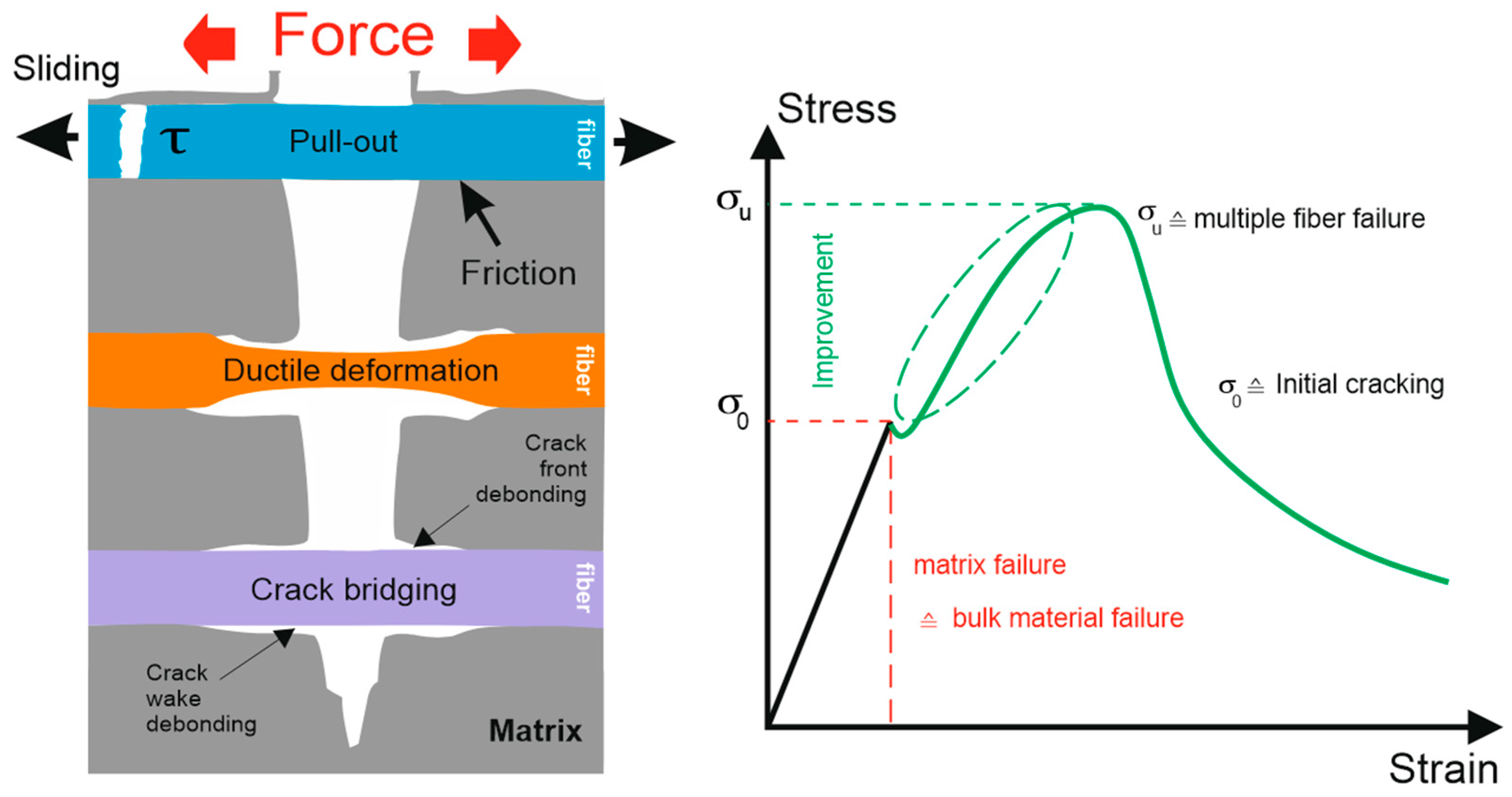
1.1. Mechanical Properties of Tungsten and Wf/W Composites

Tungsten (W) is currently the prime candidate material for the first wall armor and in particular for the highly loaded components such as the divertor of future nuclear fusion reactors. However, pure tungsten is inherently brittle below the ductile–brittle transition temperature (DBTT), and cracking could lead to a complete loss of function of the respective wall component [1,2,3,4,5,6,7]. Another issue for the mechanical properties of tungsten is the randomly distributed ultimate tensile strength (UTS). The weakest point in the component determines the fracture toughness, and therefore the material’s lifetime is difficult to predict [8,9,10,11]. To mitigate this problem and to improve the toughness and reproducibility of tungsten-based components, tungsten fiber-reinforced tungsten (Wf/W) metal matrix composites are being developed [10,12,13,14,15,16,17,18,19,20,21,22]. As shown in Figure 1, extrinsic toughening mechanisms such as fiber pull-out, ductile deformation, and/or crack bridging are applied to promote a pseudo-ductile behavior that significantly increases the application range of Wf/W composites compared to brittle tungsten. More information can be found in [6,13,23,24].

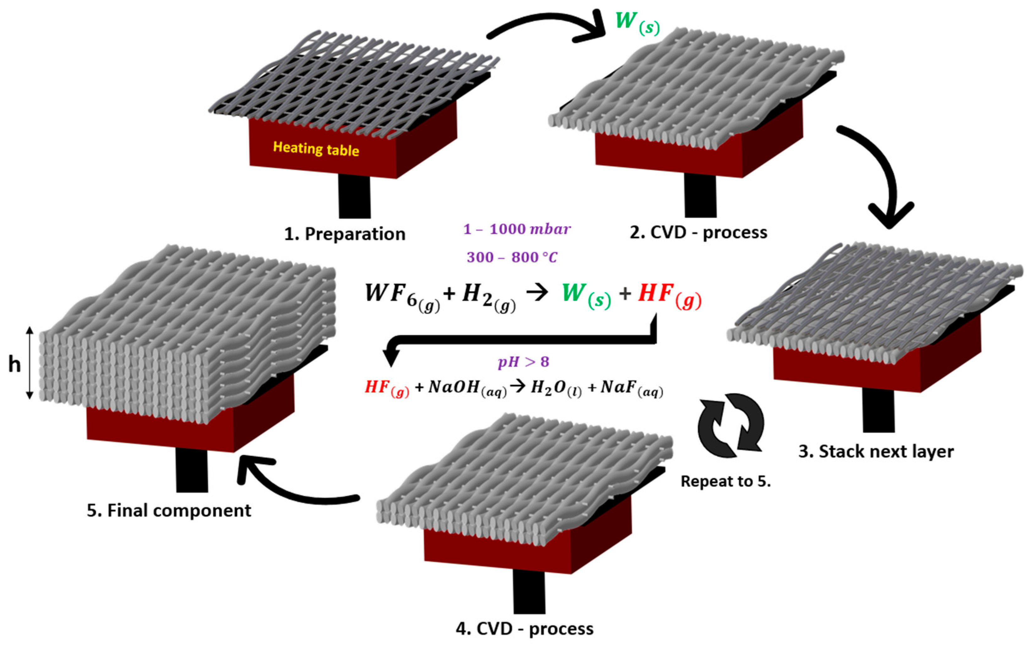
1.2. Production of Wf/W via Chemical Vapor Deposition (CVD)

One of the most reliable methods to produce a dense Wf/W composite is the use of the heterogeneous reaction between tungsten hexafluoride (WF6) and hydrogen (H2), forming solid tungsten on the W-fibers and gaseous hydrogen fluoride (HF). The toxic HF is extracted and neutralized with an alkalic sodium hydroxide solution. The process conditions for the chemical vapor deposition vary between 300–800 °C and 1–1000 mbar in a vacuum reaction chamber, using argon gas to prevent oxidation. The modelling of the highly sensitive reaction kinetics and the influence of each production parameter has been studied and is further described in [26,27,28,29]. Based on this knowledge and a series of process optimizations such as the integration of a preheating system, it is now possible to deposit pure tungsten very reproducibly on the fiber surfaces in a layer-by-layer process. Here, the theoretical and practical deposition rates show very high agreement.
A visual representation of the layer-by-layer technique is provided in Figure 2, which illustrates how the required composite thickness (h) is achieved.
In order to maintain the performance of the material under fusion conditions and to improve the mechanical properties even further, an oxide–ceramic interface, e.g., yttria interface, is necessary [5,6,7,25,30,31,32,33,34]. To merely demonstrate the advantages of the fiber-reinforcement, the application of an interlayer is not essential for initial experiments since the samples are not tested in a fusion environment. Therefore, the samples used in this work were obtained without an interlayer to reduce the fabrication effort.

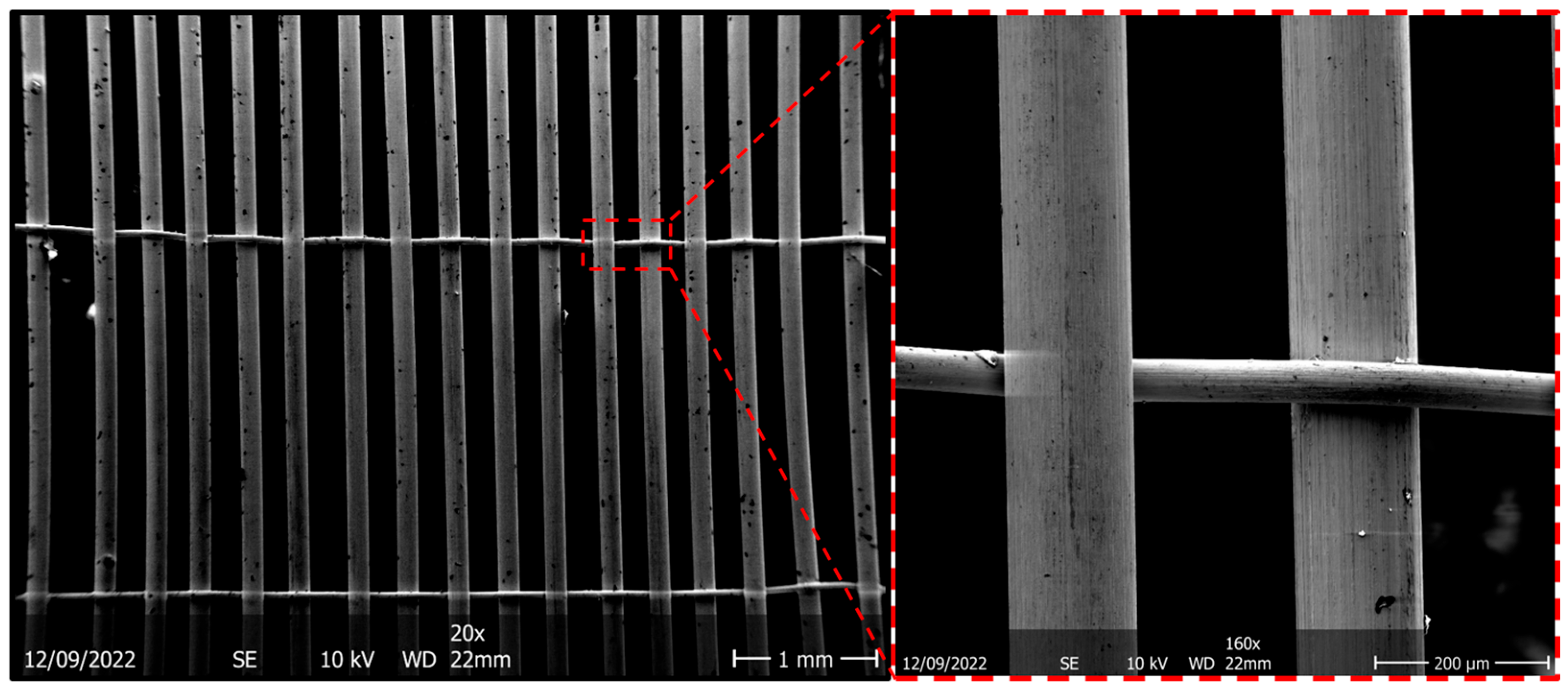
1.3. Development of New Tungsten Preforms

Up to now, the state of the art has been the usage of preforms, which are depicted in Figure 3. These preforms are based on single filaments of potassium-doped tungsten wires with diameters of 150 µm warp and 50 µm weft filaments [17,35].
In Figure 4, 25 layers of these base fabrics have been stacked with the CVD process to reach the geometrical range of the potential application field. Despite having remarkable mechanical properties, as presented in [17], single wire-based fabrics are not suitable for an industrial scale-up when stacked layer-by-layer due to the high risk of delamination between each individual layer caused by the high stiffness of the 150 µm fibers. Therefore, the layer-spacing is not homogeneously distributed, which makes it challenging to achieve consistent mechanical properties.
In order to enhance the mechanical properties of the base fabrics, the utilization of higher strength fiber bundles was targeted through the introduction of two new yarn-based textile preforms, as detailed in [36,37]. These preforms, as illustrated in Figure 5, were constructed using 20 µm W-fibers, with the goal of increasing the flexibility of the base fabrics and ensuring sufficient flattening of each layer.
Both fabrics use radial braided yarns with 7 core and 16-sleeve filaments (R.B. 16 + 7) for the warp material. This yarn was selected due to its superior mechanical properties after infiltration with CVD-W, a high fiber volume fraction, high microstructure homogeneity, and an increased flexibility compared to single fibers with a diameter of 150 µm [16]. As a weft material, the fabric type 1 (a) uses a single filament with a diameter of 50 µm, and type 2 (b) uses the yarn R.B. 16 + 7. In order to upscale Wf/W composites for industrial use, it is important to determine which new fabric type performs best and results in the best mechanical properties when processed into a solid composite. Additionally, it is important to investigate if the yarn-based fabrics represent an appropriate base material for a layer-by-layer CVD-process. To evaluate the mechanical properties of the fibers, mechanical cyclic loading tests must be conducted to demonstrate that Wf/W does not exhibit brittle fracture behavior under cyclic loading.

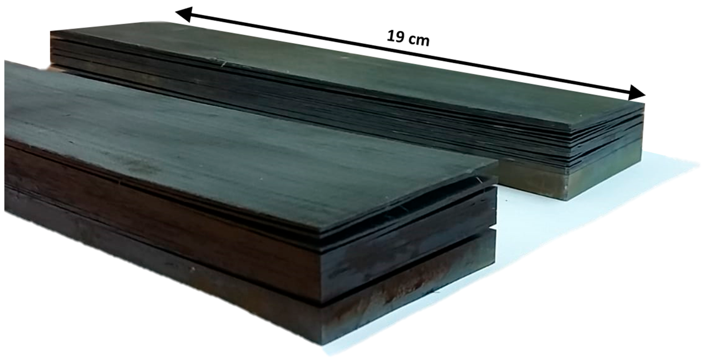
2. Comparison of Bulk Wf/W Using Yarn-Based Preforms
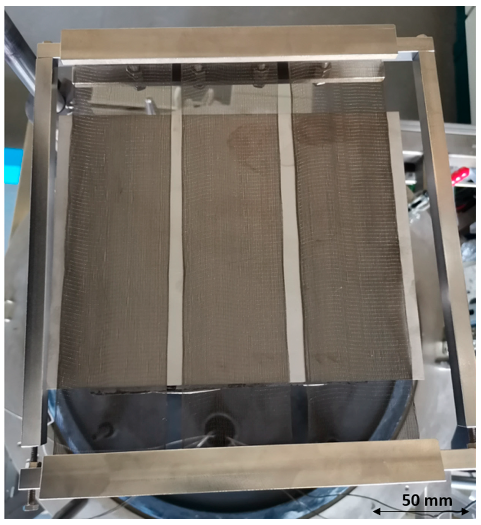
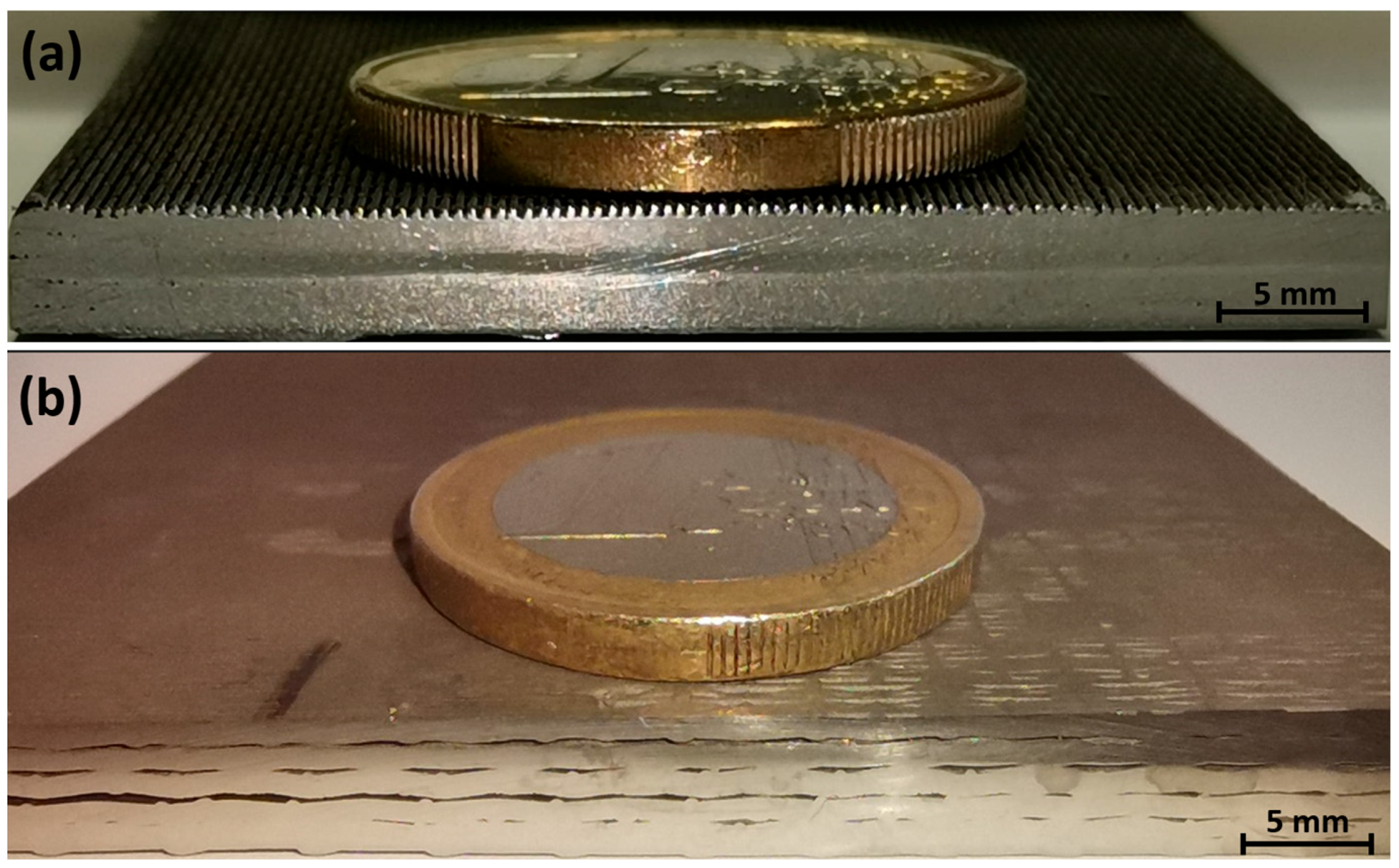
2.1. Production

The two new base fabrics depicted in Figure 5 were cut into pieces measuring 5.8 × 19.5 cm2 using electrical discharge machining (EDM). After cutting, the preforms were cleaned and dried before being clamped in a specimen holder as shown in Figure 6 to stretch and smooth the fabrics as much as possible. Here, it can be seen that three fabrics can be coated in parallel, but only one multi-layer sample for each fabric type could be produced due to the limited amount of the base material.
For all batches, the heating table was maintained at a temperature of 540 °C, and the reaction chamber was kept at an absolute pressure of 120 mbar.
A gas flow rate of 12,500 sccm for hydrogen and 1000 sccm for WF6 (with a H2:WF6 ratio of 12.5:1) was utilized. The use of a weft yarn in the manufacturing process resulted in an inhomogeneous spacing between the warp and weft materials. In order to ensure, that any 2D gaps between the warp and weft materials were closed with CVD-W, a higher process time of 3 h for type 2 was selected compared to 2.5 h for type 1.

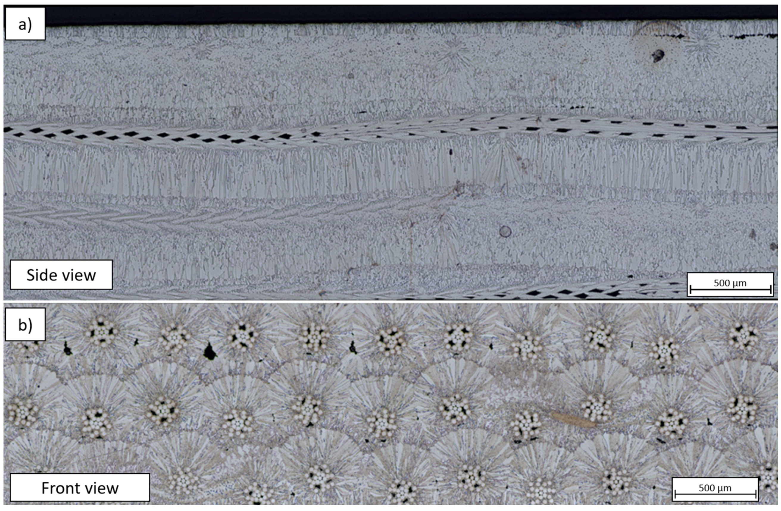
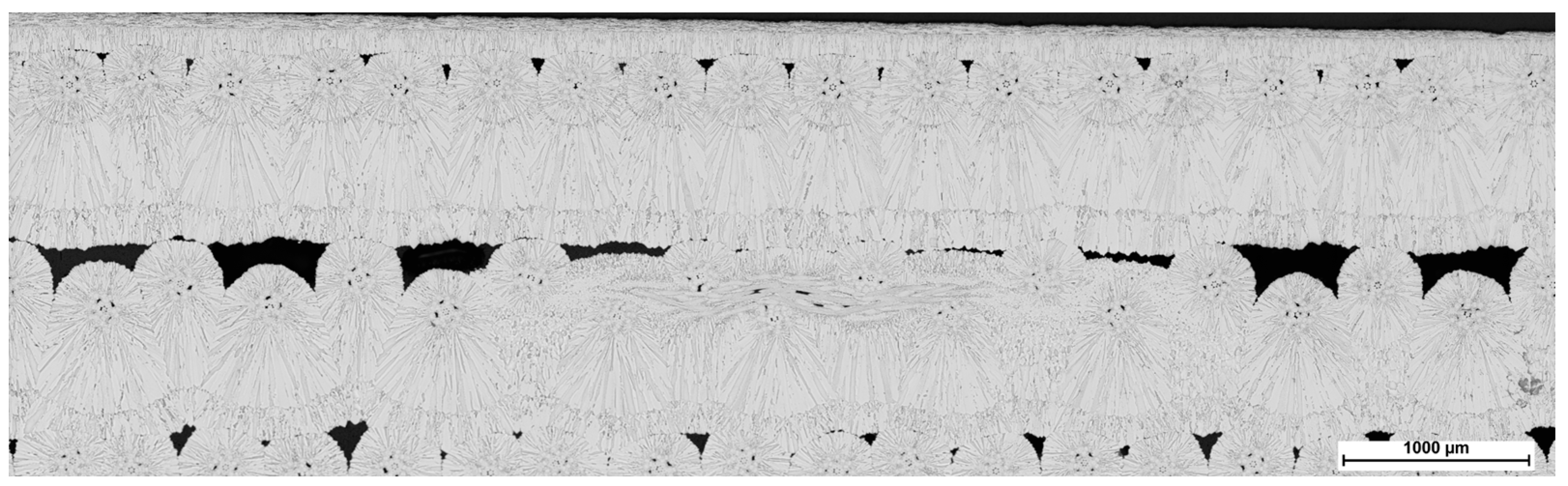
2.2. Optical Analysis, Density and Fiber Volume Fraction

Figure 7 shows a representative top and side view of the bulk materials produced, based on the example of type 2. It can be seen in the upper picture that the 2D surface of each batch could be closed completely. This shows that the chosen parameters are suitable to produce a homogenous matrix.
Figure 8 shows a comparison of the cross-sectional surface of bulk composite type 1 (a) and type 2 (b) on a macroscopic scale. The cross-sectional microstructure of each sample is shown in Figure 9 for fabric type 1 and in Figure 10 for the type 2.
The composite material comprised of fabric type 1 fabrics exhibit a macroscopic resemblance to solid tungsten blocks. However, upon close examination through larger magnification, it is revealed that the material displays small, perforated structures within each yarn. Here, both the constituent yarns and fabric layers exhibit a homogeneous distribution throughout the material. Conversely, the interlayer spacing in type 2 composites is relatively wide, leading to noticeable macroscopic gaps. Since composite type 1 had a shorter deposition time, the thickness of CVD-W between each layer was lower compared to type 2. This results in a significantly higher fiber volume fraction, ranging between 14–17%, in contrast to 7–10% in type 2. Despite the higher fiber volume fraction, the measured relative average density of the type 1 composite, determined using the Archimedean principle with five cut specimens, was only slightly higher at 97.14 ± 0.3% compared to 96.59 ± 0.5% for type 2. It is important to note, that the cut specimens for Type 2 had a more similar appearance to those of type 1 than those depicted in Figure 8b. Cutting specimens at more inhomogeneous areas of the produced composite, as depicted in Figure 8b, would likely result in a lower density. To conduct a statistically significant analysis, several specimens from different areas should be cut and tested. Nonetheless, the measured average densities are, especially for type 1, significantly higher than the maximum relative density of 92% realized for the single-fiber based fabrics presented in [17].

2.3. Mechanical Characterization

In order to investigate which material performs better under mechanical stress, KLST-type specimens were cut according to DIN EN ISO 179-1:2000 from each of the composites produced using EDM and further subjected to monotonic and cyclic three-point bending tests. A tensile testing machine equipped with a 5 kN load cell (TIRAtest 2820, Nr. R050/01 from TIRA GmbH, integrated with OPTO ENGINEERING-TC4 M004-C) was utilized for all mechanical tests described below. The setup is shown in Figure 11. Here, the camera objective, the test samples, and the stamp of the testing machine can be seen. For evaluation, the testing time, absolute force, machine displacement, and video images were captured at room temperature.

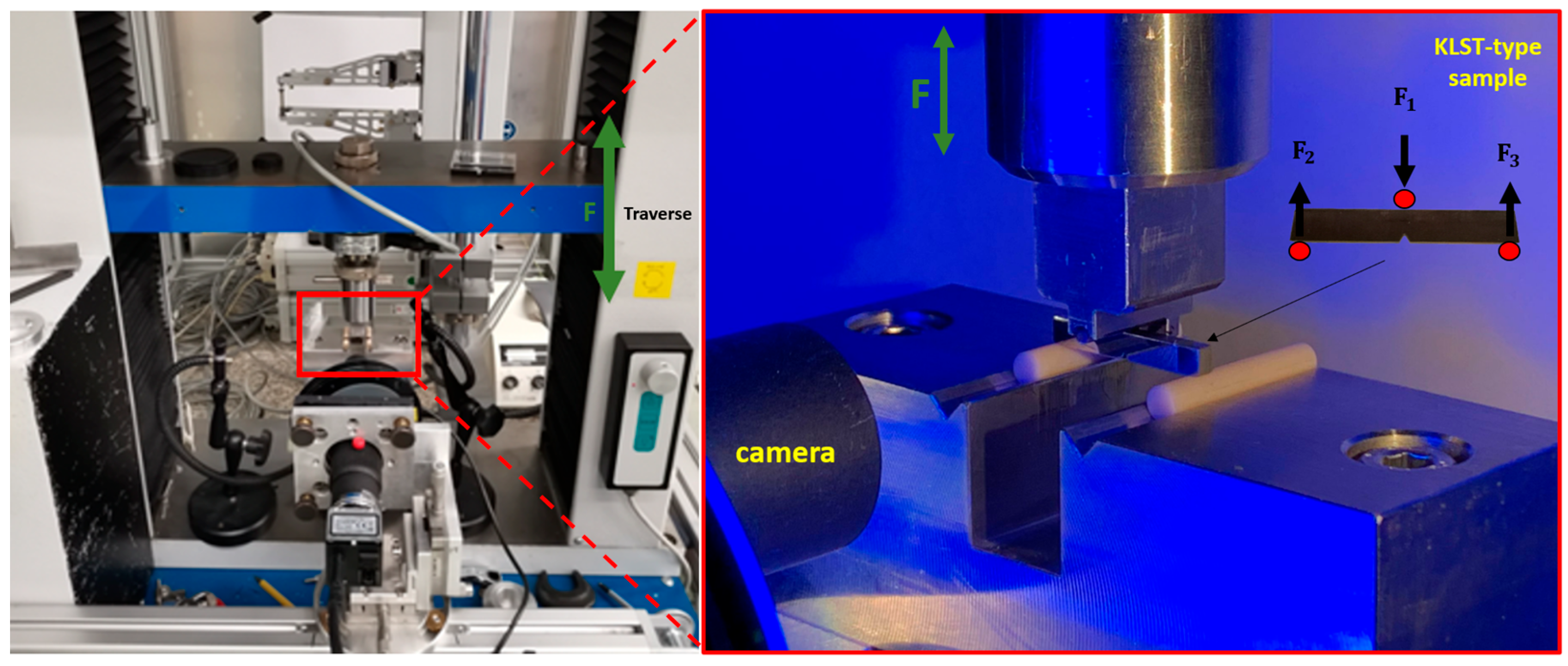
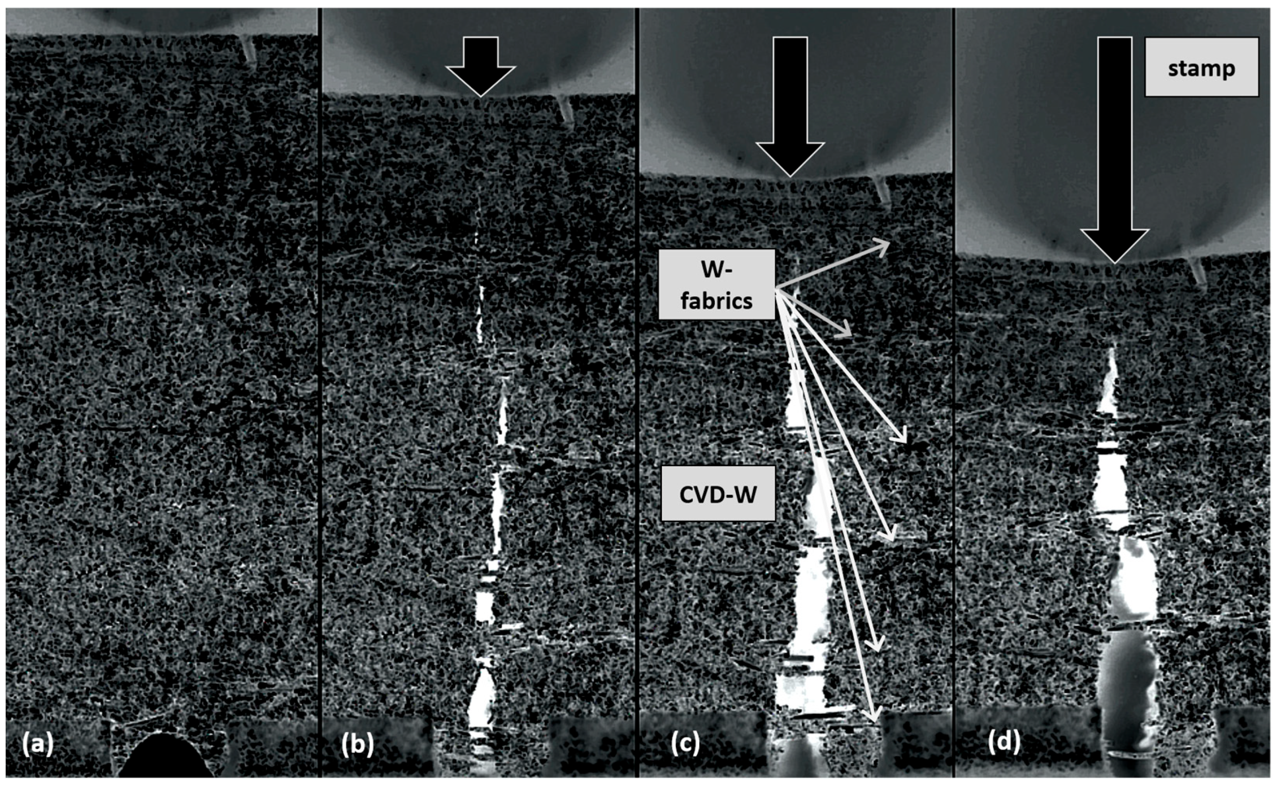
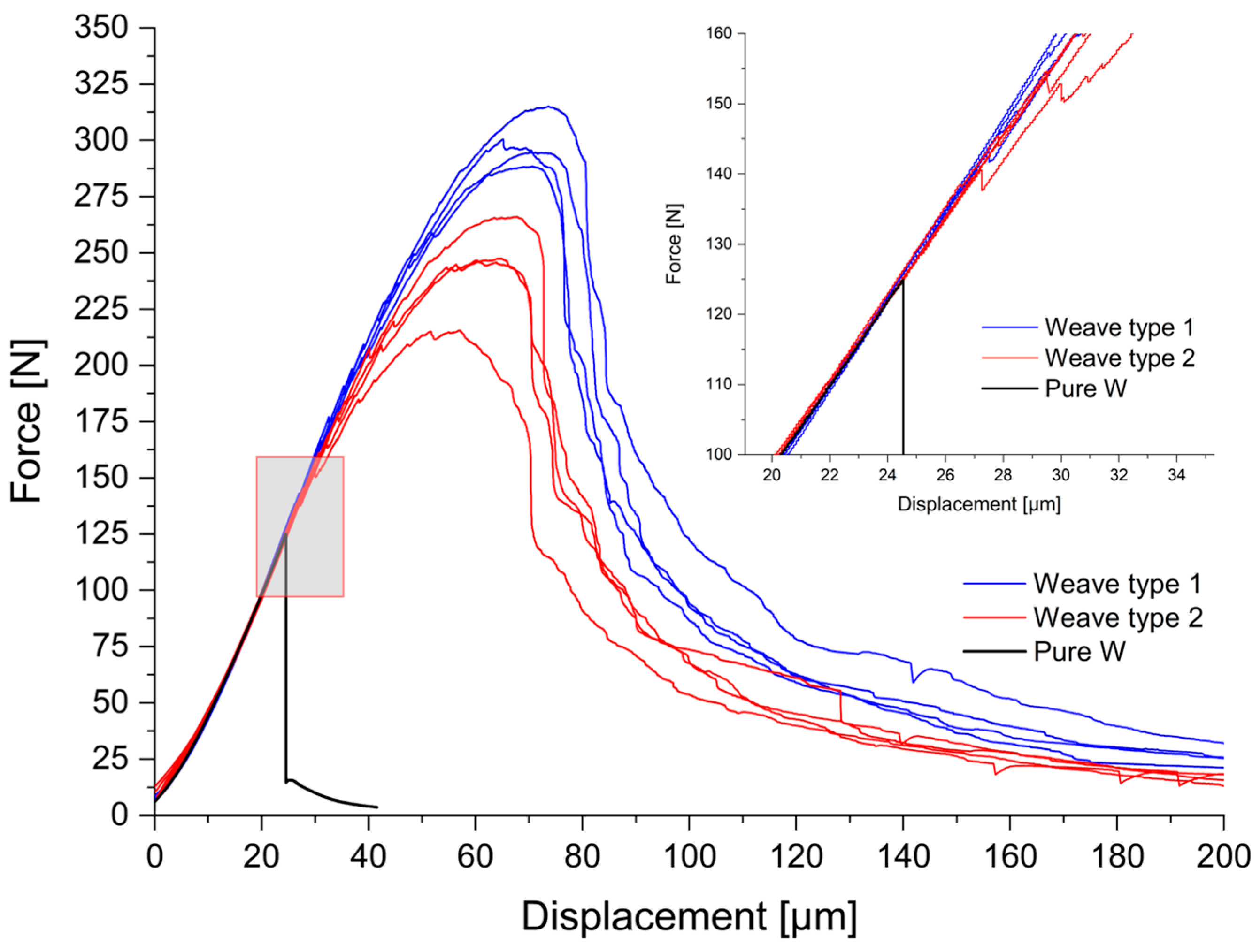
2.3.1. Monotonic Three-Point Bending Tests with KLST-Type Samples

In Figure 12, a representative crack behaviour of one of the samples is depicted, starting unloaded in (a) to fully broken in (d).
In Figure 13, the obtained force–displacement curves of all samples are presented and compared to pure, field-assisted, sintered W-powders, sintered at 1900 °C and 50 MPa with a 93% rel. density.
The results presented in Figure 13 and the accompanying fracture images in Figure 12 provide convincing evidence for the theoretical pseudo-ductile mechanisms outlined in Figure 1. In particular, the crack bridging mechanism can be clearly observed on the macroscopic scale. In order to further examine the microstructure of the broken composites, Figure 14 presents two SEM-images: the left image (a) illustrates the crack bridging mechanism in detail. The right image (b) highlights, that some fibers display ductile necking (marked in green), while others exhibit brittle fracture (marked in red).
Although not all fibers exhibit ductile necking, the load–displacement curves in Figure 13 do not show abrupt failure. At this point, it has to be highlighted again that the composites were produced without an yttria interface, which would decrease the fiber matrix adhesion and should further improve the performance of the material and, e.g., the necking behavior [5,6,7]. It appears that as the number of fibers within the matrix increases, so does the likelihood of contributing to the mechanisms of pseudo-ductile materials. As a result, the reproducibility of mechanical properties improves with a higher number of W-fibers in the CVD-W matrix, but this hypothesis needs to be confirmed through further experiments. The produced composite type 1 demonstrates a superior performance with a significantly higher mean maximum load capacity of 299.74 N compared to 243.96 N for type 2. The reproducibility of the load–displacement curves is also superior for type 1, which can be attributed to the more homogeneous fabric distribution as observed in Figure 9 and Figure 10. Upon examination of the enlarged area in the upper right corner of Figure 13, initial cracking can be observed in the same range as for pure, sintered tungsten without fiber reinforcement. However, instead of a brittle fracture behavior as seen for the sintered sample, both of the composites show a stable crack growth, resulting in an increase of the maximum load capacity.

2.3.2. Cyclic Tests with KLST-Type Samples

In order to evaluate the KLST-type specimen under cyclic loading, the average maximum load was firstly measured for each composite type. Subsequently, 10,000 load cycles were applied between 50–90% of the avg. respective maximum load, with a frequency of 1 Hz, on each material. Figure 15 shows a representative overview for composite type 1 before (a) and after (b) cyclic loading, highlighting the crack growth in yellow. It can be seen, that the specimen remained consistent without the occurrence of complete failure after the experiment.
However, due to the high number of cycles and corresponding high amount of data, only the beginning and the end of cyclic loading were captured in images. During the experimental investigation, it was observed that the cracks in the matrix responded to changes in the load with a slight opening and closing behavior. This cyclic loading resulted in the propagation of cracks, which became more pronounced with an increasing number of loading cycles, which leads to the question, at which number of cycles the material would break completely.

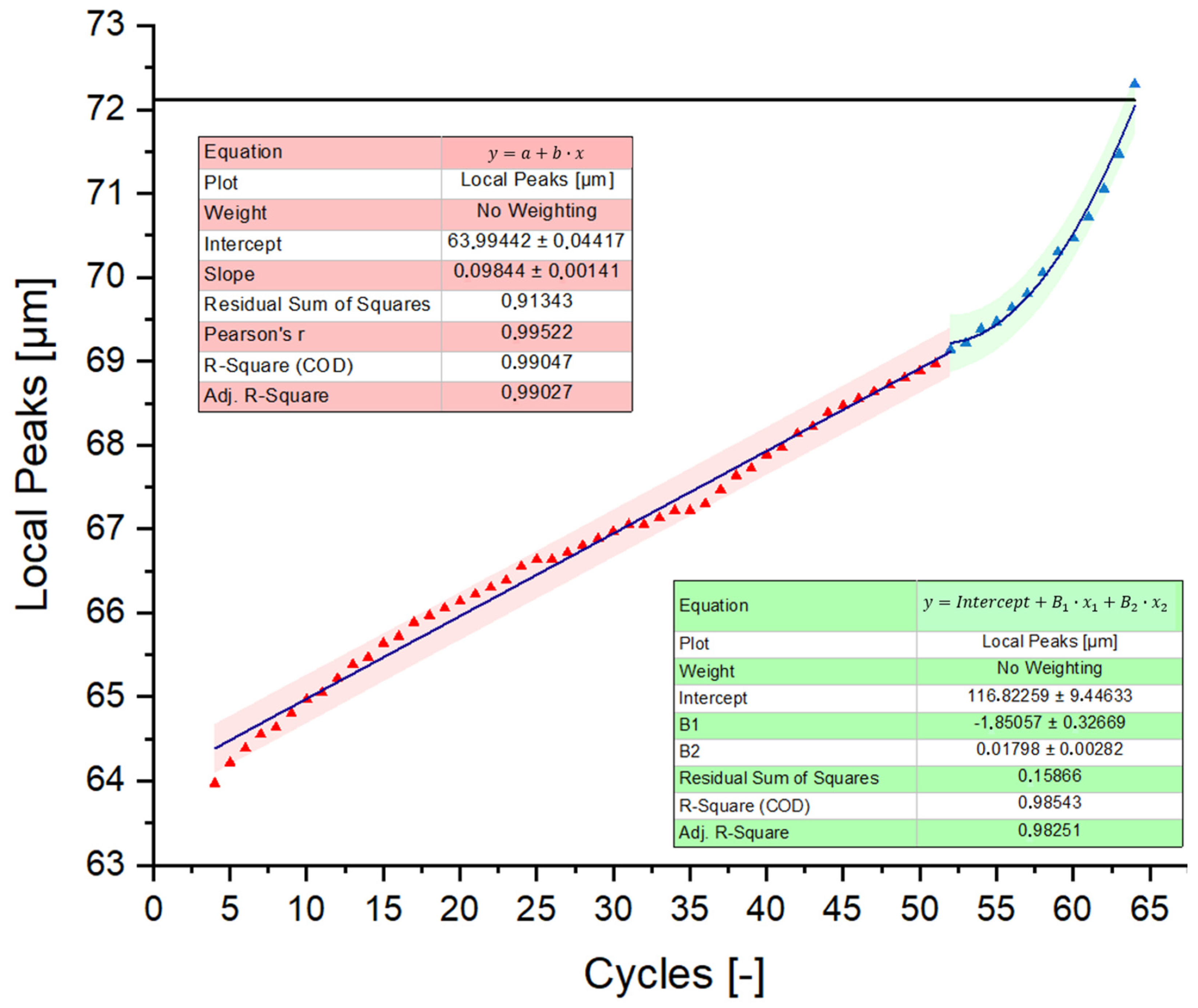
2.3.3. Prediction of the Fatigue Behavior

It can be seen in Figure 16 that the displacement over the total number of cycles for the 10,000 load cycles is not constant, which means that the sample shows signs of fatigue over time.
In the literature, fatigue behavior prediction is often achieved through the measurement of the crack length over a given number of cycles [38,39]. As mentioned above, the amount of data for such a high number of cycles does not allow the evaluation with this approach. Therefore, the goal in this work is to extrapolate the displacement movement over the total number of cycles instead. In order to demonstrate that the trend can be extrapolated up to the point of critical displacement, which was measured first hand by monotonic three-point bending tests, the average critical displacement value of the better performing composite type 1 was initially determined with the data presented in Figure 13 and averaged to a value of 72.11 ± 1.95 μm. Following that, the upper boundary of the mechanical load cycles was further increased from 90% to 95% (150–285 N) in order to reduce the necessary number of cycles to break the samples. This cyclic load range was applied at a frequency of 1 Hz until the material experienced complete failure. Figure 17 shows the corresponding displacement in micrometers over the time in seconds. The red marks indicate the maximum peaks of the sinusoids, and the black line shows the average critical displacement, which was determined from the fully broken samples in initial tests. It is evident that once the predicted critical displacement of the sample is exceeded, a complete failure of the sample occurs in the next cycle. This supports the assumption, that cyclic loading tests and classic three-point bending tests have matching critical displacement limits, and therefore the fatigue behavior over time can be extrapolated for cyclic loading. To predict the fatigue behavior, a linear regression was performed on the entire dataset. In Figure 18, the red marks represent the displacement maxima of each sinusoid in Figure 17, plotted against the number of cycles. The fit of the blue trendline describes the trend with an adjusted R-square of 85.99%.
Therefore, it seems, that a simple linear regression can be used to make initial predictions of the number of mechanical load cycles for each load range. Using the same critical displacement limit and the data in Figure 16 with the specimen that had been tested for 10,000 cycles between 50–90% of the rel. maximum load, a linear regression suggests that the cycling load could potentially be increased to approx. 58,000 cycles for this load range.
In order to improve the accuracy of the fatigue behavior predictions, the function can be split into two parts. The data suggest, that as the displacement trend approaches the point of critical displacement, the linear trend function shifts towards an exponential growth function. By separating the data into ranges below and above 96% of the relative critical displacement value, the coefficient of determination (adjusted R-square fit) shows that below 96%, the data fits 99.03% to that of a linear function, and above 96%, an exponential growth function fits with 98.25% to the dataset. This behavior is illustrated in Figure 19. Therefore, the simple linear regression can be further improved if needed.

3. Conclusions and Outlook

The results show that the usage of yarn-based fabrics for CVD stacking are not just increasing the fiber volume fractions and densities of Wf/W composites, but also increasing the reproducibility compared to the results presented in [17] for 150 µm single fiber-based fabrics. In Table 1, the material properties of each composite material produced are shown in an overview. The improvement can be explained with a significant increase of the total number of fibers per volume unit (one yarn has 23 fibers with a total diameter of approx. 190 µm), an improved processability, and a more homogeneous fiber distribution within the CVD-W matrix. This applies in particular for type 1, where the layer spacing is lower due to the reduced thickness of the weft material. Therefore, the usage of W-yarns as a warp material in combination with single weft fiber is a promising combination for the scale-up of Wf/W.
It should be emphasized that the application of an interface should further reduce the fiber–matrix adhesion and enhance the pseudo-ductile mechanisms such as the “pull-out” effect. The presented method to predict the fatigue behavior under cyclic mechanical loading tests might also pose an option to predict the lifetime under different stress conditions, such as thermal cyclic loading. However, the developed method needs to be further validated and investigated on further test samples.
Future efforts will focus on developing a more efficient manufacturing process that allows for the same or better material properties at significantly lower production costs and times. Alternative production approaches such as the combination of the field-assisted sintering technology with the CVD process or the infiltration of stacked fabrics (CVI) are currently under investigation and will be presented in the future.

Author Contributions

Conceptualization, A.L., J.W.C., M.T. and H.G.; Methodology, A.L., J.W.C., D.S., Y.M., J.R. and A.T.; Software, L.R. and H.G.; Validation, J.W.C. and J.R.; Formal analysis, A.L., T.H., L.R. and B.G.; Investigation, A.L., D.S., L.R. and A.T.; Data curation, J.W.C., Y.M., B.G. and J.G.-J.; Writing—original draft, A.L.; Writing—review & editing, J.W.C., J.R., L.R., H.G., C.L., K.T.-B. and J.G.-J.; Visualization, A.L.; Supervision, J.W.C., C.L., K.T.-B. and J.G.-J.; Project administration, C.L. All authors have read and agreed to the published version of the manuscript.

Funding

This work has been funded by the European Union via the Euratom Research and Training Programme (Grant Agreement No. 101052200—EUROfusion).

Data Availability Statement

Please contact the corresponding authors for further information.

Acknowledgments

This work has been carried out within the framework of the EUROfusion Consortium, funded by the European Union via the Euratom Research and Training Programme (Grant Agreement No. 101052200—EUROfusion). Views and opinions expressed are, however, those of the author(s) only and do not necessarily reflect those of the European Union or the European Commission. Neither the European Union nor the European Commission can be held responsible for them.

Conflicts of Interest

The authors declare no conflict of interest.

References

  1. Pitts, R.; Carpentier, S.; Escourbiac, F.; Hirai, T.; Komarov, V.; Lisgo, S.; Kukushkin, A.; Loarte, A.; Merola, M.; Naik, A.S.; et al. A full tungsten divertor for ITER: Physics issues and design status. J. Nucl. Mater. 2013, 438, S48–S56. [Google Scholar] [CrossRef]
  2. Linsmeier, C.; Rieth, M.; Aktaa, J.; Chikada, T.; Hoffmann, A.; Houben, A.; Kurishita, H.; Jin, X.; Li, M.; Litnovsky, A.; et al. Development of advanced high heat flux and plasma-facing materials. Nucl. Fusion 2017, 57, 092007. [Google Scholar] [CrossRef]
  3. Philipps, V. Tungsten as material for plasma-facing components in fusion devices. J. Nucl. Mater. 2011, 415, S2–S9. [Google Scholar] [CrossRef]
  4. Coenen, J.W. Fusion Materials Development at Forschungszentrum Jülich. Adv. Eng. Mater. 2020, 22, 1901376. [Google Scholar] [CrossRef]
  5. Evans, A.; Zok, F.; Davis, J. The Role of Interfaces in Fiber-Reinforced Brittle Matrix Composites. Compos. Sci. Technol. 1991, 42, 3–24. [Google Scholar] [CrossRef]
  6. Mao, Y.; Coenen, J.; Riesch, J.; Sistla, S.; Almanstötter, J.; Jasper, B.; Terra, A.; Höschen, T.; Gietl, H.; Linsmeier, C.; et al. Influence of the interface strength on the mechanical properties of discontinuous tungsten fiber-reinforced tungsten composites produced by field assisted sintering technology. Compos. Part A Appl. Sci. Manuf. 2018, 107, 342–353. [Google Scholar] [CrossRef]
  7. Shu, R.; Mao, Y.; Coenen, J.W.; Terra, A.; Liu, C.; Schönen, S.; Riesch, J.; Linsmeier, C.; Broeckmann, C. Interface and mechanical properties of the single-layer long fiber reinforced Wf/W composites fabricated via field assisted sintering technology. Mater. Sci. Eng. A 2022, 857, 144098. [Google Scholar] [CrossRef]
  8. Gandhi, C.; Ashby, M. Fracture-Mechanism Maps for Materials Which Cleave—Fcc, Bcc and Hcp Metals and Ceramics. Acta Metall. Mater. 1979, 27, 1565–1602. [Google Scholar] [CrossRef]
  9. Gietl, H.; Olbrich, S.; Riesch, J.; Holzner, G.; Höschen, T.; Coenen, J.; Neu, R. Estimation of the fracture toughness of tungsten fibre-reinforced tungsten composites. Eng. Fract. Mech. 2020, 232, 107011. [Google Scholar] [CrossRef]
  10. Mao, Y.; Coenen, J.W.; Riesch, J.; Sistla, S.K.; Almanstötter, J.; Reiser, J.; Terra, A.; Chen, C.; Wu, Y.; Raumann, L.; et al. Fracture behavior of random distributed short tungsten fiber-reinforced tungsten composites. Nucl. Fusion 2019, 59, 086034. [Google Scholar] [CrossRef]
  11. Zinkle, S.; Ghoniem, N. Operating temperature windows for fusion reactor structural materials. Fusion Eng. Des. 2000, 51–52, 55–71. [Google Scholar] [CrossRef]
  12. Zhang, L.; Jiang, Y.; Fang, Q.; Zhang, T.; Wang, X.; Liu, C. Toughness and microstructure of tungsten fibre net-reinforced tungsten composite produced by spark plasma sintering. Mater. Sci. Eng. A 2016, 659, 29–36. [Google Scholar] [CrossRef]
  13. Zhang, L.; Jiang, Y.; Fang, Q.; Xie, Z.; Miao, S.; Zeng, L.; Zhang, T.; Wang, X.; Liu, C. Microstructure and mechanical properties of tungsten composite reinforced by fibre network. Front. Mater. Sci. 2017, 11, 190–196. [Google Scholar] [CrossRef]
  14. Zhang, L.; Jiang, Y.; Fang, Q.; Liu, R.; Xie, Z.; Zhang, T.; Wang, X.; Liu, C. Comparative Investigation of Tungsten Fibre Nets Reinforced Tungsten Composite Fabricated by Three Different Methods. Metals 2017, 7, 249. [Google Scholar] [CrossRef]
  15. Mao, Y.; Coenen, J.W.; Riesch, J.; Sistla, S.; Chen, C.; Wu, Y.; Raumann, L.; Neu, R.; Linsmeier, C.; Broeckmann, C. Spark Plasma Sintering Produced W-Fiber-Reinforced Tungsten Composites. In Spark Plasma Sintering of Materials: Advances in Processing and Applications; Springer Nature: Cham, Switzerland, 2019; pp. 239–261. [Google Scholar] [CrossRef]
  16. Treitz, M. Development of Production Routines for Fibre Reinforced Metal Matrix Composites. Master’s Thesis, University of Applied Sciences Munich, Munich, Germany, 2019. [Google Scholar]
  17. Schwalenberg, D.; Coenen, J.W.; Riesch, J.; Hoeschen, T.; Mao, Y.; Lau, A.; Gietl, H.; Raumann, L.; Huber, P.; Linsmeier, C.; et al. Large-Scale Tungsten Fibre-Reinforced Tungsten and Its Mechanical Properties. J. Nucl. Eng. 2022, 3, 306–320. [Google Scholar] [CrossRef]
  18. Zhao, S.X.; Liu, F.; Qin, S.G.; Song, J.P.; Luo, G.N. Preliminary Results of W Fiber Reinforced W (Wf/W) Composites Fabricated with Powder Metallurgy. Fusion Sci. Technol. 2013, 64, 225–229. [Google Scholar] [CrossRef]
  19. Riesch, J.; Höschen, T.; Linsmeier, C.; Wurster, S.; You, J.-H. Enhanced toughness and stable crack propagation in a novel tungsten fibre-reinforced tungsten composite produced by chemical vapour infiltration. Phys. Scr. 2014, T159, 014031. [Google Scholar] [CrossRef]
  20. Riesch, J.; Han, Y.; Almanstötter, J.; Coenen, J.W.; Höschen, T.; Jasper, B.; Zhao, P.; Linsmeier, C.; Neu, R. Development of tungsten fibre-reinforced tungsten composites towards their use in DEMO—Potassium doped tungsten wire. Phys. Scr. 2016, T167, 014006. [Google Scholar] [CrossRef]
  21. Mao, Y.; Coenen, J.; Sistla, S.; Liu, C.; Terra, A.; Tan, X.; Riesch, J.; Hoeschen, T.; Wu, Y.; Broeckmann, C.; et al. Design of tungsten fiber-reinforced tungsten composites with porous matrix. Mater. Sci. Eng. A 2021, 817, 141361. [Google Scholar] [CrossRef]
  22. Mao, Y.; Coenen, J.W.; Sistla, S.; Tan, X.; Riesch, J.; Raumann, L.; Schwalenberg, D.; Höschen, T.; Chen, C.; Wu, Y.; et al. Development of tungsten fiber-reinforced tungsten with a porous matrix. Phys. Scr. 2020, T171, 014030. [Google Scholar] [CrossRef]
  23. Terentyev, D.; Riesch, J.; Lebediev, S.; Bakaeva, A.; Coenen, J. Mechanical properties of as-fabricated and 2300 °C annealed tungsten wire tested up to 600 °C. Int. J. Refract. Met. Hard Mater. 2017, 66, 127–134. [Google Scholar] [CrossRef]
  24. Zhao, P.; Riesch, J.; Höschen, T.; Almanstötter, J.; Balden, M.; Coenen, J.; Himml, R.; Pantleon, W.; von Toussaint, U.; Neu, R. Microstructure, mechanical behaviour and fracture of pure tungsten wire after different heat treatments. Int. J. Refract. Met. Hard Mater. 2017, 68, 29–40. [Google Scholar] [CrossRef]
  25. Coenen, J.W.; Antusch, S.; Aumann, M.; Biel, W.; Du, J.; Engels, J.; Heuer, S.; Houben, A.; Hoeschen, T.; Jasper, B.; et al. Materials for DEMO and reactor applications—Boundary conditions and new concepts. Phys. Scr. 2015, T167, 014002. [Google Scholar] [CrossRef]
  26. Raumann, L.; Coenen, J.W.; Riesch, J.; Mao, Y.; Gietl, H.; Höschen, T.; Linsmeier, C.; Guillon, O. Modeling and validation of chemical vapor deposition of tungsten for tungsten fiber reinforced tungsten composites. Surf. Coat. Technol. 2019, 381, 124745. [Google Scholar] [CrossRef]
  27. Gietl, H.; Riesch, J.; Coenen, J.; Höschen, T.; Neu, R. Production of tungsten-fibre reinforced tungsten composites by a novel continuous chemical vapour deposition process. Fusion Eng. Des. 2019, 146, 1426–1430. [Google Scholar] [CrossRef]
  28. Raumann, L.; Coenen, J.; Riesch, J.; Mao, Y.; Schwalenberg, D.; Wegener, T.; Gietl, H.; Hoschen, T.; Linsmeier, C.; Guillon, O. Modeling and experimental validation of a W-f/W-fabrication by chemical vapor deposition and infiltration. Nucl. Mater. Energy 2021, 28, 101048. [Google Scholar] [CrossRef]
  29. Raumann, L.; Coenen, J.; Riesch, J.; Mao, Y.; Schwalenberg, D.; Gietl, H.; Linsmeier, C.; Guillon, O. Improving the W Coating Uniformity by a COMSOL Model-Based CVD Parameter Study for Denser W-f/W Composites. Metals 2021, 11, 1089. [Google Scholar] [CrossRef]
  30. You, J.; Visca, E.; Bachmann, C.; Barrett, T.; Crescenzi, F.; Fursdon, M.; Greuner, H.; Guilhem, D.; Languille, P.; Li, M.; et al. European DEMO divertor target: Operational requirements and material-design interface. Nucl. Mater. Energy 2016, 9, 171–176. [Google Scholar] [CrossRef]
  31. Mao, Y.; Engels, J.; Houben, A.; Rasinski, M.; Steffens, J.; Terra, A.; Linsmeier, C.; Coenen, J. The influence of annealing on yttrium oxide thin film deposited by reactive magnetron sputtering: Process and microstructure. Nucl. Mater. Energy 2017, 10, 1–8. [Google Scholar] [CrossRef]
  32. Garrison, L.; Katoh, Y.; Snead, L.; Byun, T.; Reiser, J.; Rieth, M. Irradiation effects in tungsten-copper laminate composite. J. Nucl. Mater. 2016, 481, 134–146. [Google Scholar] [CrossRef]
  33. Coenen, J.; Berger, M.; Demkowicz, M.; Matveev, D.; Manhard, A.; Neu, R.; Riesch, J.; Unterberg, B.; Wirtz, M.; Linsmeier, C. Plasma-wall interaction of advanced materials. Nucl. Mater. Energy 2017, 12, 307–312. [Google Scholar] [CrossRef]
  34. Palaniyappan, S.; Trautmann, M.; Mao, Y.; Riesch, J.; Gowda, P.; Rudolph, N.; Coenen, J.W.; Neu, R.; Wagner, G. Yttria-Coated Tungsten Fibers for Use in Tungsten Fiber-Reinforced Composites: A Comparative Study on PVD vs. CVD Routes. Coatings 2021, 11, 1128. [Google Scholar] [CrossRef]
  35. Gietl, H.; von Muller, A.; Coenen, J.; Decius, M.; Ewert, D.; Hoschen, T.; Huber, P.; Milwich, M.; Riesch, J.; Neu, R. Textile pre-forms for tungsten fibre-reinforced composites. J. Compos. Mater. 2018, 52, 3875–3884. [Google Scholar] [CrossRef]
  36. Coenen, J.W.; Huber, P.; Lau, A.; Raumann, L.; Schwalenberg, D.; Mao, Y.; Riesch, J.; Terra, A.; Linsmeier, C.; Neu, R. Tungsten fiber reinforced tungsten (Wf/W) using yarn based textile preforms. Phys. Scr. 2021, 96, 124063. [Google Scholar] [CrossRef]
  37. Coenen, J.; Treitz, M.; Gietl, H.; Huber, P.; Hoeschen, T.; Raumann, L.; Schwalenberg, D.; Mao, Y.; Riesch, J.; Terra, A.; et al. The use of tungsten yarns in the production for W-f/W. Phys. Scr. 2020, T171, 014061. [Google Scholar] [CrossRef]
  38. Hertzberg, R.; Vinci, R.; Hertzberg, J. Deformation and Fracture Mechanics of Engineering Materials, 6th ed.; Wiley: Hoboken, NJ, USA, 2020. [Google Scholar]
  39. Meyers, M.; Chawla, K. Mechanical Behavior of Materials, 2nd ed.; Cambridge University Press: Cambridge, UK; New York, NY, USA, 2009. [Google Scholar]
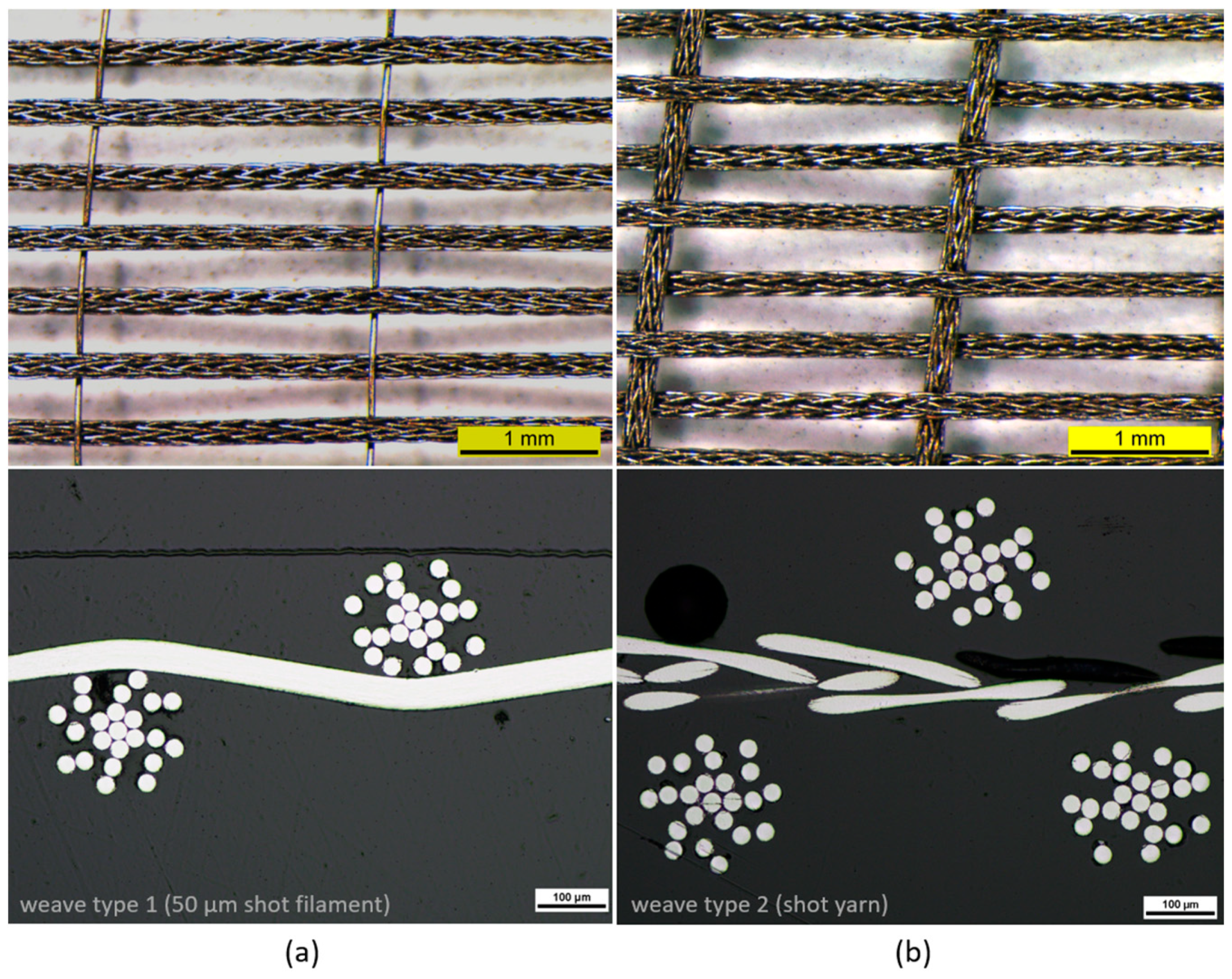
Figure 1. Energy dissipation mechanisms in a fiber-based metal matrix composite: pull-out of fibers, ductile deformation, crack bridging and crack wake, and front debonding of the applied ceramic oxide-based interface [20,25].
Jne 04 00027 g001
Figure 2. Layer-by-layer CVD process principle.
Jne 04 00027 g002
Figure 3. Preform type based on single-fibers microscopic structure. Image was obtained with scanning electron microscope (SEM) Carl Zeiss LEODSM982.
Jne 04 00027 g003
Figure 4. CVD stacking of 25 layers of single wire-based preforms [17].
Jne 04 00027 g004
Figure 5. Comparison: (a) Fabric type 1 with 50 µm weft filament; (b) fabric type 2 with weft yarn. Top pictures show the tungsten fabrics as fabricated and were obtained via Zeiss optical microscope. Button images show metallographic cuts of each type and were made with a Nikon Eclipse LV 150 NL.
Jne 04 00027 g005
Figure 6. CVD process applied on three parallel coated fabrics.
Jne 04 00027 g006
Figure 7. Representative images of top and side view for both WfW composites after CVD stacking (type 2).
Jne 04 00027 g007
Figure 8. Solid composites of six layers via CVD: Fabric 1 (a), Fabric 2 (b).
Jne 04 00027 g008
Figure 9. Wf/W composite based on type 1. Image obtained with a Zeiss optical microscope. (a) shows the side view of the composite, (b) shows the front view.
Jne 04 00027 g009
Figure 10. Front view of the Wf/W composite based on type 2. Image obtained with a Zeiss optical microscope.
Jne 04 00027 g010
Figure 11. TIRAtest 2820, Nr. R050/01 setup with KLST-type Wf/W samples for three-point bending tests and cyclic loading tests.
Jne 04 00027 g011
Figure 12. Crack behaviour during three-point bending test from (a) unloaded state, (b) initial cracking, (c) clear cracking, and (d) almost full broken sample.
Jne 04 00027 g012
Figure 13. Force over displacement curves of KLST-type samples of fabric type 1, type 2, and sintered W-sample (Pure W powders 5 µm, field-assisted sintering at 1900 °C, 50 MPa, 93% rel. density).
Jne 04 00027 g013
Figure 14. Representative fracture images of type 2 for both composites, images taken with SEM Carl Zeiss LEO DSM 982. (a) illustrates crack bridging, and (b) depicts ductile necking in the green-marked region and brittle fracture in the red-marked region.
Jne 04 00027 g014
Figure 15. Cyclic mechanical loading tests of composite type 1 before (a) and after (b) 10,000 load cycles between 50–90% of the rel. max. load capacity. The crack growth is highlighted in yellow.
Jne 04 00027 g015
Figure 16. Cyclic loading tests between 50–90% of the avg. max. load. Representative overview for both composites.
Jne 04 00027 g016
Figure 17. Cyclic loading tests between 50–95% of the avg. max. load of composite type 1.
Jne 04 00027 g017
Figure 18. Maxima of each sinusoid displacement [µm] over the total number of mechanical load cycles [−]. The red dots show each maximum, the blue line shows the trendline of a linear regression.
Jne 04 00027 g018
Figure 19. Split function of the displacement [µm] over total numbers of cycles [−]. The green marked area shows the values below 96% of the critical displacement value as a linear trend, and the red marked area describes the values above 96% as an exponential growth.
Jne 04 00027 g019
Table 1. Comparison table.
AspectType 1Type 2
Weft materialYarn R.B. 16 + 7Yarn R.B. 16 + 7
Warp material50 µm filamentYarn R.B. 16 + 7
Avg. relative density97.14%96.59%
Fiber volume fraction14–17%7–10%
Processing Multilayervery goodmacroscopic gaps
Avg. max. load (KLST-type samples)299.74 N243.96 N
10,000 cycles between 50–90% of rel. max. loadSample intact—prediction possibleSample intact—prediction not possible
ReproducibilityVery goodOK
Disclaimer/Publisher’s Note: The statements, opinions and data contained in all publications are solely those of the individual author(s) and contributor(s) and not of MDPI and/or the editor(s). MDPI and/or the editor(s) disclaim responsibility for any injury to people or property resulting from any ideas, methods, instructions or products referred to in the content.

