Article

The Double-Disk Diamond Window as Backup Broadband Window Solution for the DEMO Electron Cyclotron System

1
Institute for Applied Materials (IAM), Karlsruhe Institute of Technology (KIT), 76344 Eggenstein-Leopoldshafen, Germany
2
Institute for Pulsed Power and Microwave Technology (IHM), Karlsruhe Institute of Technology (KIT), 76344 Eggenstein-Leopoldshafen, Germany
*
Author to whom correspondence should be addressed.
J. Nucl. Eng. 2022, 3(4), 342-351; https://doi.org/10.3390/jne3040021
Submission received: 10 October 2022 / Revised: 10 November 2022 / Accepted: 11 November 2022 / Published: 15 November 2022

Abstract

:
The second variant of the electron cyclotron heating and current drive system in DEMO considers the deployment of 2 MW power Gaussian microwave beams to the plasma by frequency steering. Broadband optical grade chemical vapor deposition diamond windows are thus required. The Brewster-angle window represents the primary choice. However, in the case of showstoppers, the double-disk window is the backup solution. This window concept was used at ASDEX Upgrade for injection of up to 1 MW at four frequencies between 105 and 140 GHz. This paper shows computational fluid dynamics conjugated heat transfer and structural analyses of such a circumferentially water-cooled window design aiming to check whether it might be used for DEMO microwave beam scenarios. This design was then characterized with respect to different parameters. Temperature and thermal stress results showed that it is a feasible window solution for DEMO, but safety margins against limits shall be increased by introducing design features able to make the fluid more turbulent. A first design change is proposed, showing that, in combination with a higher inlet flow rate, the maximum temperature in the disks can be reduced from 238 to 186 °C, leading, therefore, to lower thermal gradients and stresses in the window.

1. Introduction

Two design options are currently under investigation for the electron cyclotron heating and current drive (EC H&CD) system required in the European DEMO to heat up the plasma and to control the magneto-hydrodynamic (MHD) instabilities, especially the neoclassical tearing modes (NTMs), and also the thermal instability of the plasma [1]. In the first option, the angular steering concept, consisting of antenna launchers with mirrors steered by dedicated actuators, is used to deploy the electron cyclotron (EC) power at different positions in the plasma. On the contrary, the second option features fixed-angle antenna launchers connected to frequency step-tunable gyrotrons [2]. The frequency steering concept is used for a different radial EC power deposition by tuning the gyrotron frequency in the range of a few seconds. The target is the tuning in steps of 2–3 GHz over a range of ±10 GHz around the main two frequencies to be selected among 136, 170 and 204 GHz [3].
Broadband diamond window solutions are thus required both on the torus and gyrotron sides of the EC H&CD system. The chemical vapor deposition (CVD) diamond Brewster-angle window is the primary choice, with a minimum diameter of 180 mm of the disk, required for a 63.5 mm aperture allowing 2 MW continuous wave (CW) propagation. Until 2020, several diamond growth experiments were carried out by Diamond Materials [4] aiming at a target of an optical grade disk with 180 mm diameter and 2 mm thickness [5,6]. Excellent results were obtained with reference to the diamond deposition, polishing and quality (represented by loss tangent measurements). In addition, the design of such a window has been advanced with reference to cooling layout and characterized by a consistent and parametric set of analyses in view of the window prototyping activity foreseen in the European DEMO conceptual design phase (2021–2027) [6].
However, in case of showstoppers, the double-disk diamond window is the backup broadband solution. This window concept was used to design and manufacture a torus window in the context of the EC H&CD system at ASDEX Upgrade for injection up to 1 MW microwaves at four selected frequencies between 105 and140 GHz [7,8]. In this paper, first, the possibility of using the double-disk diamond window within the boundary conditions of the EC H&CD system in DEMO was investigated by computational fluid dynamics (CFD) conjugated heat transfer analyses in order to check the fluid behavior and the thermal performance of the window with respect to the reference microwave beam scenario of 2 MW at 204 GHz (worst scenario). Subsequently, the sensitivity of the design with respect to different mass flow rate, loss tangent (tanδ), beam radius and frequency was checked. Last, the resulting temperature distribution was transferred to a FEM structural analysis to validate the design against the allowable limits.
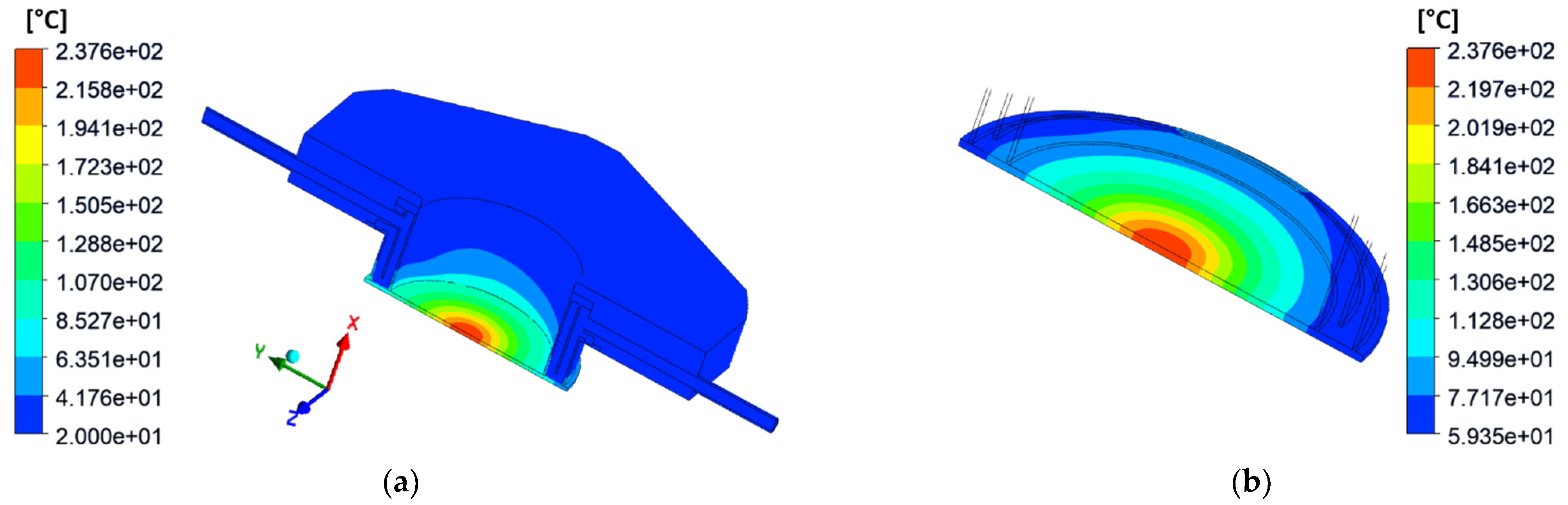
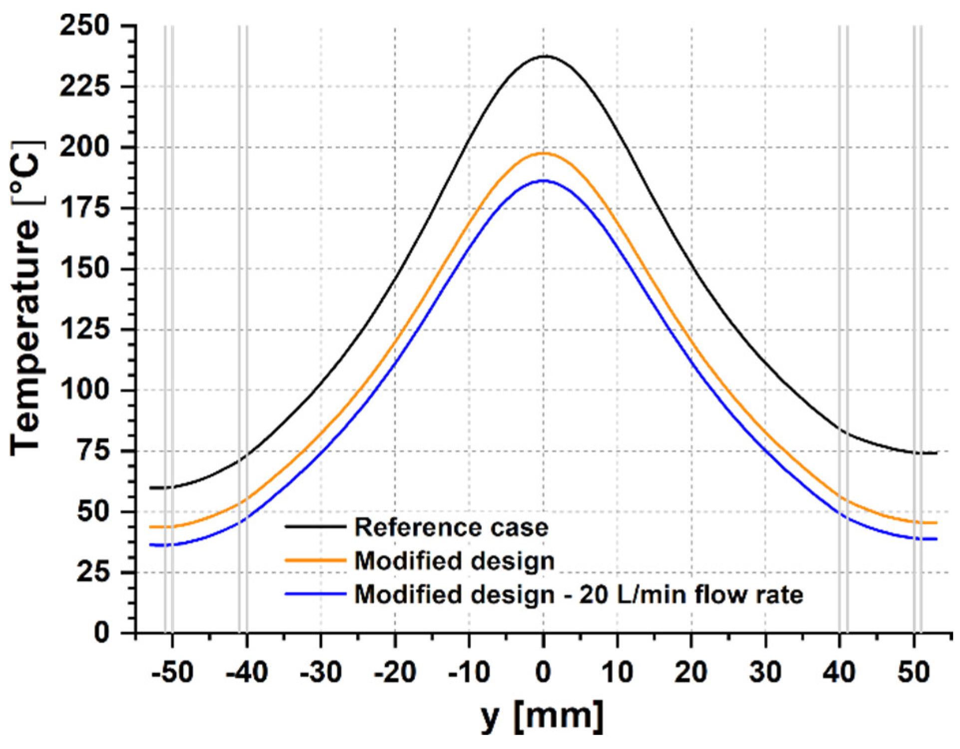
Temperature and thermal stress results showed that the double disk window is a feasible window solution for DEMO, but safety margins against limits shall be increased by introducing design features able to make the fluid more turbulent. A first design change is proposed, showing that, in combination with a higher inlet flow rate, the maximum temperature in the disks can be reduced from 238 to 186 °C, leading, therefore, to lower thermal gradients and stresses in the window.

2. Geometry of the Window

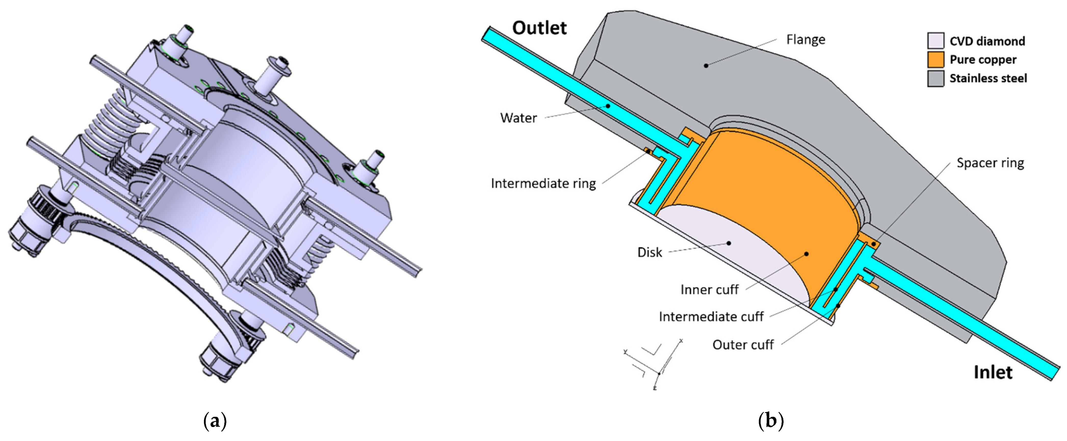
The double disk window designed and manufactured for ASDEX Upgrade is shown in Figure 1a. It consists of two parallel diamond disks of 106 mm diameter facing each other with a tunable gap of about 5 mm and having the resonant thickness of 1.80 mm for the frequency range limits of 105 and 140 GHz. The window has an aperture of 80 mm. Setting the gap to values in the range of 4.1 to 6 mm, EC power can be transmitted at other two intermediate frequencies with minimum reflected power (around 115 and 125 GHz). Each disk is integrated in a subsystem, forming a housing with the counterpart subsystem. Fine tuning of the disk interspace is performed by dedicated helical springs.
With reference to each subsystem, the disk is brazed to two copper cuffs of 1 mm thickness, allowing cooling only on one side by direct contact with water. These cuffs, named inner and outer cuffs, are brazed to a steel flange by a copper ring and spacer. An intermediate cuff is also used to force the water in the vicinity of the disk. The flange contains inlet and outlet pipes with 6 mm inner diameter and connections to the housing.
Thanks to the symmetry regarding the cooling path in the two subsystems of the window, only half of a subsystem was considered for the DEMO window analyses. The geometry for these analyses is shown in Figure 1b. The thickness of the disk was increased to 1.85 mm, being in resonant condition with the main frequencies 136, 170 and 204 GHz currently of interest for DEMO. Small geometrical simplifications, not affecting the overall results, were introduced for better quality of the mesh to generate.
Figure 1. (a) Geometry of the double-disk window designed and manufactured for ASDEX Upgrade; (b) geometry of the window used in the analyses. Reference system, nomenclature of the main parts and materials are shown.
Jne 03 00021 g001

3. Method: CFD-Conjugated Heat Transfer Analysis

Steady-state CFD conjugated heat transfer analysis was first carried out as a reference case to investigate the cooling and the thermal performance of the window shown in Figure 1b with respect to the foreseen worst beam scenario, i.e., 2 MW at 204 GHz. The code ANSYS CFX 2021 R1 was used for the analyses. Temperature-dependent properties for pure copper, CVD diamond and steel were taken from [9,10,11], while the properties directly from CFX’s library were used for the water coolant. A fine mesh was generated for the window geometry with 13.3 × 10⁶ elements. In particular, a mesh size of 0.5 mm was applied to the disk and cuffs, while, in the fluid model, a size of 0.4 mm was adopted and a very fine mesh (inflation layer with first element size of 10 µm) was generated at the boundary layer to model properly the near wall interactions (heat transfer). For the latter reason, in the analysis settings, the k-omega shear stress transport (SST) model was selected as the turbulence model.
Symmetry was applied to the xy plane (Figure 1b). A mass flow rate of 0.167 kg s−1 (10 L/min) was assumed for the inlet (0.0833 kg s−1 in the symmetric model), while a reference pressure of 0 Pa was applied to the outlet. The inlet temperature of the water was set to 20 °C. A Gaussian mm-wave beam was considered as the analysis refers to a gyrotron output window. First, the absorbed power Pabs in one disk was calculated by [12]:
P abs = P beam   π   f   t   tan δ   1 + ε r c 0
where Pabs is the absorbed power, Pbeam = 2 MW is the beam power, f = 204 GHz is the beam frequency, t = 1.85 mm is the disk thickness, tanδ = 3.5 × 10⁻⁵ is the reasonable assumed loss tangent, εr = 5.67 is the dielectric constant of diamond and c0 is the speed of light in vacuum. It turned out an absorbed power of 1847 W. As a benchmark, it is interesting to observe that, in the Brewster-angle disk configuration, with the same geometrical features and properties, using the appropriate formula also provided in [12], the absorbed power in the disk only would have been 1430 W. It means that, due to the resonance thickness, there is higher absorption in the window planar configuration of about 1.3 times. The heat load was then applied to the disk in terms of volumetric power density along the radial coordinate q (r) in W m−3 by:
  q   r = 2   P abs π   w 0 2   t e 2   r 2 w 0 2
where Pabs = 1847 W is the absorbed power in the disk, r is the radial coordinate and w0 = 20 mm is the assumed beam radius. The Gaussian distribution was normalized in order to obtain in the disk the calculated absorbed power of 1847 W.
The average y+ (the non-dimensional distance) at the cooling interface lower than 1 and average residuals of the solved equations lower than default target of 1 × 10⁻⁴, used in many engineering applications, provided confidence in the accuracy of the performed analysis. In addition, an analysis run with a much finer mesh than the reference case showed the grid independency of the results. In fact, with a mesh of 25 × 106 elements, i.e., having almost a double number of elements, no changes occurred in the results.
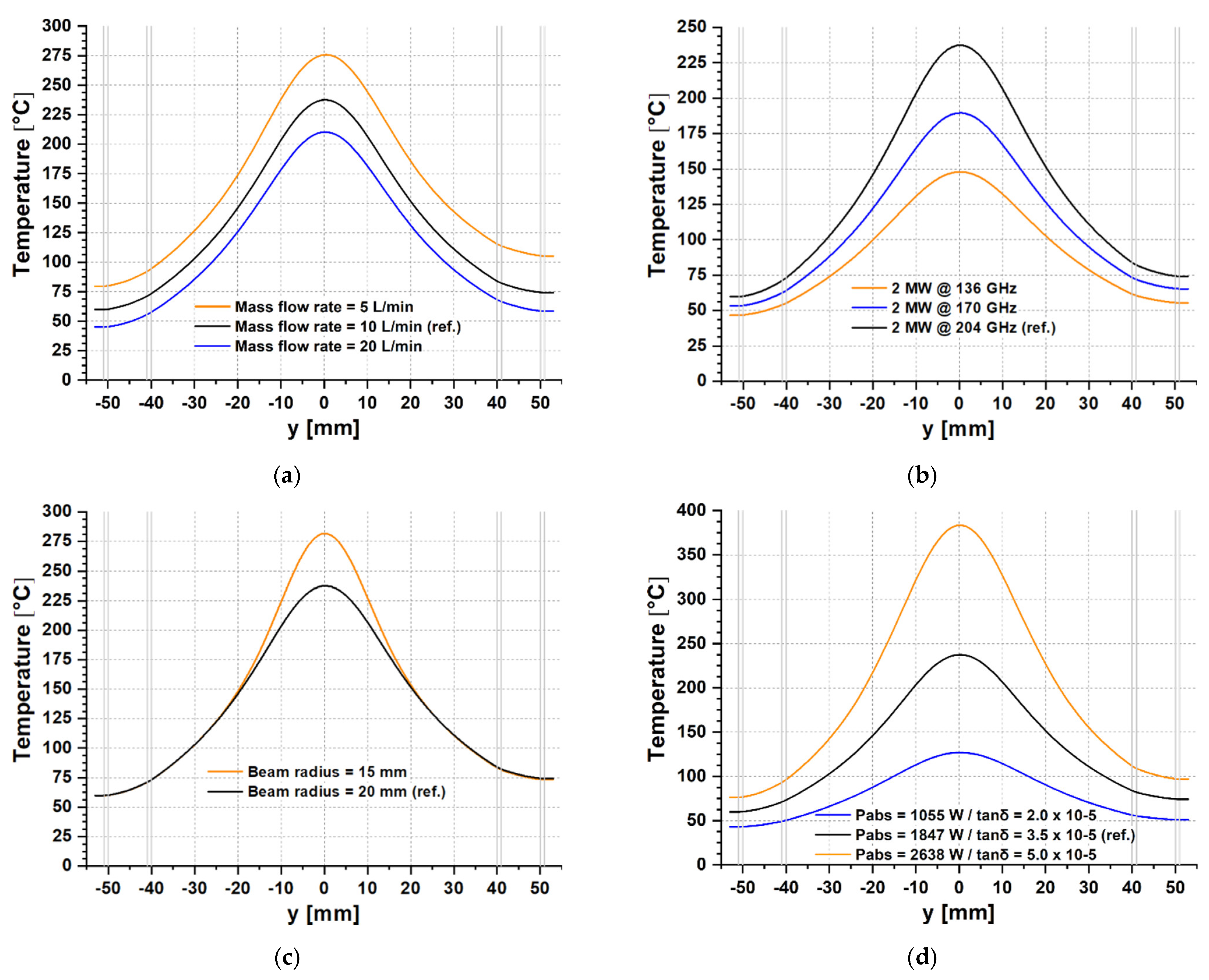
Then, additional CFD conjugated heat transfer analyses were carried out to investigate the sensitivity of this double-disk window design with respect to different mass flow rate, loss tangent, beam radius and frequency.
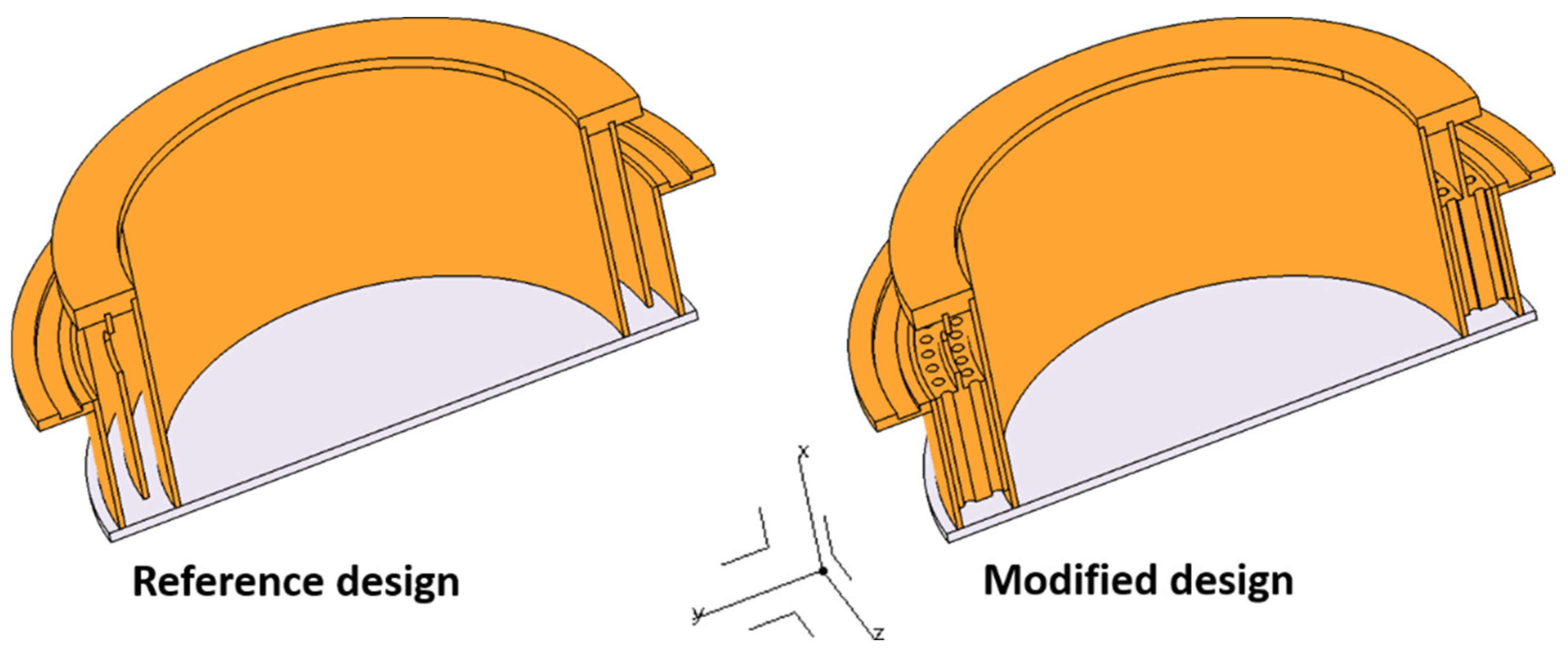
Last, a first conceptual design change was introduced to increase the fluid turbulence along the cooling path in order to improve the heat exchange and obtain lower temperatures in the window. The design change was checked by CFD conjugated heat transfer analysis to evaluate the impact on the safety margin with respect to the reference case. As shown in Figure 2, the intermediate cuff was simply modified by increasing its thickness between the inner and outer cuffs and introducing a series of holes having a diameter of 2 mm. In this way, for the same flow rate, the velocity of the fluid along the cooling path is increased with the aim to make the heat removal more effective.

4. Method: Structural Analysis

A structural analysis was performed by the code ANSYS Workbench 2021 R1 to check, in the reference case, the thermal stresses generated in the window by the beam power absorption. The residual stresses due to the brazing process are not considered. The geometry in Figure 1b (without the coolant) was used with the boundary conditions shown in 
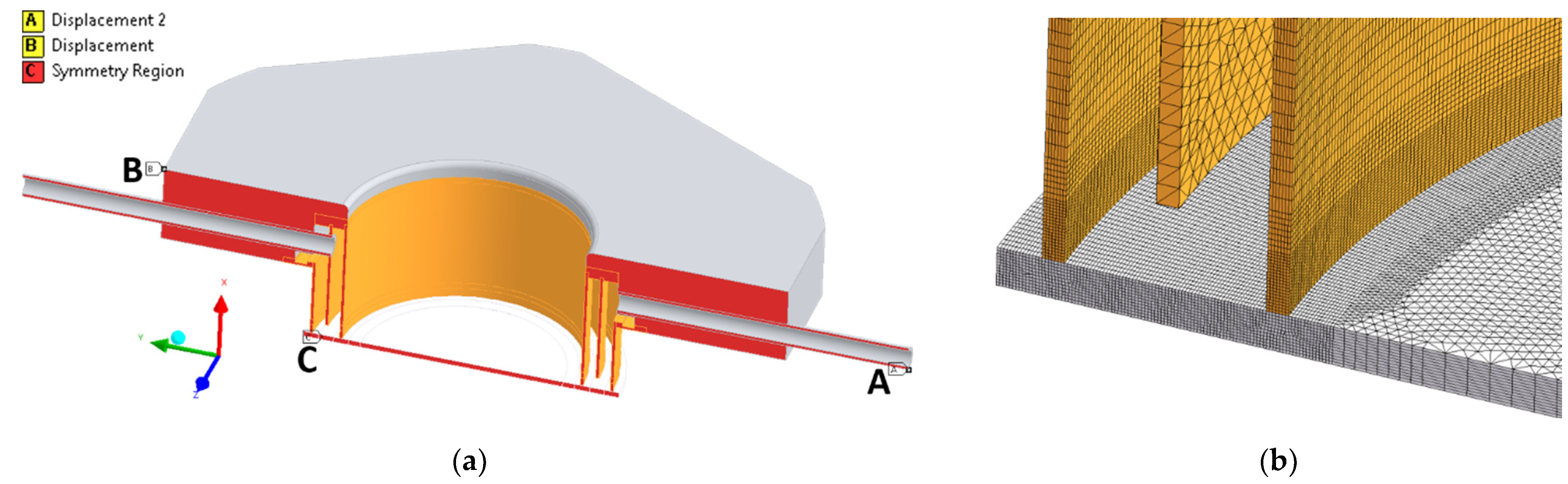
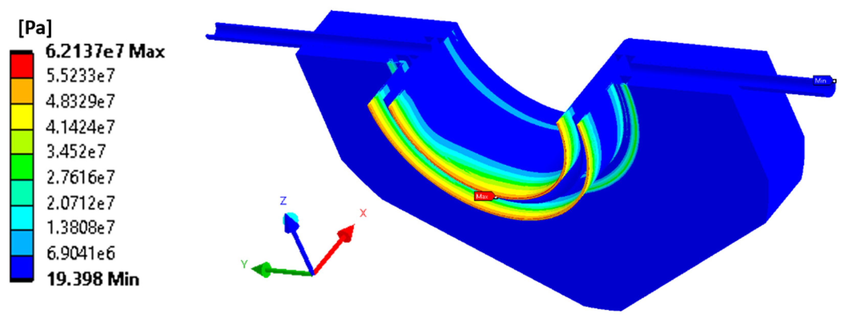
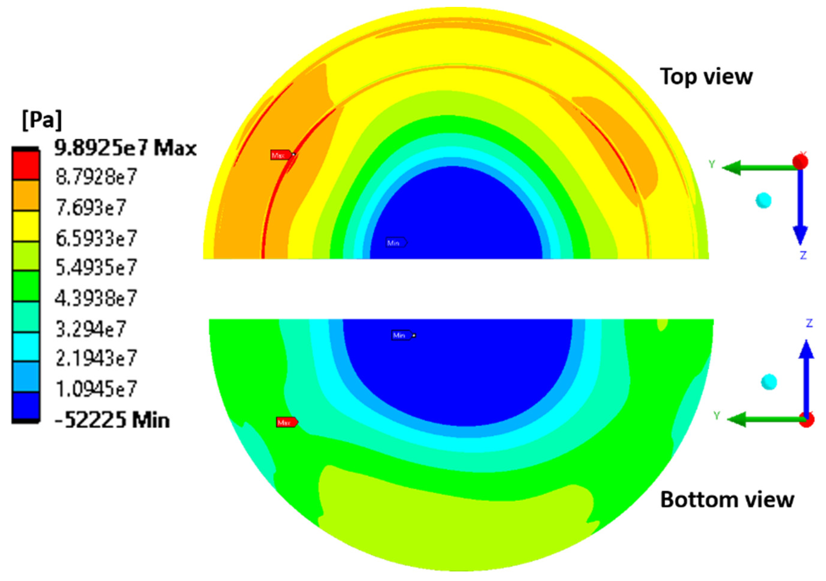
Figure 3a. Again, symmetry was applied in the xy plane, and the structure was made isostatic by applying a condition of zero displacement to all three coordinates at point B and zero displacement only to the x coordinate at the point A. The temperature distribution was applied as load and the stresses were taken in terms of first principal stresses for diamond and equivalent von Mises stresses for the metallic parts.
An accurate mesh was generated, especially at the critical regions where high stresses are expected, i.e., at the interface copper–diamond (Figure 3b). The inner and outer cuffs at the interface with the disk experience plastic deformation as the stresses become close to the yield strength of copper for the temperature range of interest (minimum yield strength of copper for plate products is 57 MPa at 80 °C [9]). A plastic steady-state structural analysis was, therefore, carried out with the temperature-dependent properties for pure copper, CVD diamond and steel taken from [9,10,11]. The multilinear isotropic hardening was used as plasticity material model for copper with stress–strain curves given for plate products at different temperatures (up to 250 °C).
Figure 3. (a) Boundary conditions applied in the structural analysis for the reference case; (b) details of the mesh generated at the disk interface with inner and outer cuffs.
Jne 03 00021 g003

5. Results and Discussion

5.1. CFD Analysis: Reference Case

Figure 4 shows the temperature distribution in the window. As expected, the maximum temperature is located at the disk center and amounts to 238 °C, with cooling water of 20 °C at the inlet. This temperature can be accepted, but it is close to the limit of 250 °C generally assumed for CVD diamond (beyond 250 °C, worsening of thermal conductivity and increasing loss tangent lead to higher losses in diamond). For instance, the limit might already be achieved in the case of a warmer coolant at the inlet. It is important to remind that, with respect to the usual window configurations, the heat is removed only on one side of the disk, leading, therefore, to higher temperatures in the system. It was calculated that the maximum temperature would decrease by about 50 °C in the case of symmetric cooling on both disk sides.
The cuffs experience a maximum temperature in the range 70–89 °C in the region in contact with the disk. The temperature distribution along the diameter at the symmetry xy plane is slightly non-axial-symmetric, with a temperature difference between the two disk edges of circa 14 °C (see Section 5.2). The difference between the center and the edge of about 170 °C provides instead the order of magnitude of the high thermal gradients generated in the diamond disk. Finally, the pressure drop in the cooling circuit amounts to 0.38 bar and the temperature increase of the water at the outlet results in 2.6 °C only.
Figure 4. (a) Contour plot of the temperature distribution in the window; (b) detailed view of the temperature distribution in the diamond disk.
Jne 03 00021 g004

5.2. CFD Analysis: Parametric Study

Figure 5 shows the results of the sensitivity study regarding the window design and Table 1 summarizes the main results for the parametric study related to the flow rate.
It immediately turns out that the assumed value of 10 L/min in the reference case (2 MW at 204 GHz) represents a kind of minimum boundary condition at the inlet. In fact, going to 5 L/min, the maximum temperature increases to 276 °C, beyond the limit for diamond (Figure 5a). On the other side, it might be beneficial to increase the flow rate to 20 L/min as temperature reduces by about 30 °C. However, due to higher turbulent flow, the pressure drop would increase by a factor of 4 (Table 1).
Currently, the main frequencies of interest for DEMO are 136, 170 and 204 GHz at 2 MW. When the lower frequencies of 170 and 136 GHz are selected, the absorbed power in the disk decreases, respectively, from 1847 W to 1539 W and 1231 W, resulting in maximum temperatures of 190 and 148 °C, as shown in Figure 5b. As expected, the safety margin with respect to the temperature limit increases with resulting lower thermal gradients in the disk. Then, with respect to beam radius, the 20 mm value in the reference case already represents an upper boundary limit as the aperture radius of the window is 40 mm. Reducing the beam radius to 15 mm, the maximum temperature increases by 20% (282 °C), well beyond the limit (Figure 5c).
Finally, the thermal response of the window was checked with reference to the tanδ. This is a crucial parameter as its variation highly affects the absorbed power in the disk and thus the temperatures achieved in the structure. Unfortunately, the brazing process carried out to join the disk to the cuffs causes a certain degradation of the initial tanδ measured in the bare disk, as well as, potentially, also the manufacturing process of the window itself. Thanks to the high-quality CVD diamond yielded by the state-of-the-art industrial production, with a bare diamond disk having a tanδ of circa 1.0 × 10⁻⁵, the assumption of tanδ = 3.5 × 10⁻⁵ conducted in the reference case can be considered quite reasonable to account for the above-mentioned factors.
As described in §3, this tanδ value leads to an absorbed power of 1847 W and a maximum temperature of 238 °C, close to the limit for diamond. Figure 5d shows that, in the case of higher tanδ, assuming a conservative value of 5.0 × 10⁻⁵, the disk would experience a maximum temperature of 384 °C (corresponding to 2638 W absorbed power), well above the limit. For completeness of information, in the optimistic case of tanδ = 2.0 × 10⁻⁵, the temperature would be 127 °C only.

5.3. CFD Analysis: Conceptual Design Change

The thermal results in §5.1 showed that the double-disk window with the geometry in Figure 1b can work for the DEMO worst beam scenario, even if it is close to the temperature limit of diamond and there is no actual safety margin to counteract, e.g., a higher tanδ degradation or even a higher water temperature at the inlet. Figure 6 shows the comparison of the thermal results between the reference case and the design change described in Figure 2.
It can be observed that the maximum temperature in the disk decreases from 238 °C to 198 °C, i.e., by 17%, showing that features aiming to increase the fluid turbulence can really be useful in increasing the safety margins of the window. In addition, based on the outcome from the parametric analysis, this effect of design change was combined with the beneficial effect of increasing the mass flow rate to 20 L/min by running further analysis. This was the only possible combination as, for instance, the value of beam radius is already at its upper boundary limit. It can be concluded from Figure 6 that it is possible to achieve a maximum temperature of 186 °C, well below the limit assumed for diamond. For completeness of information, the pressure drop in the circuit amounts to 0.41 bar for the modified design and to 1.52 bar when the flow rate of 20 L/min is considered in the modified design. As expected, the fluid being more turbulent, the pressure drop in the cooling circuit increases, but the comparison with the correspondent values in Table 1 shows only a slight increase.

5.4. Structual Analysis

The stress results are shown in Figure 7 and Figure 8. As expected, the power being absorbed by the disk, maximum stresses are in the disk and the regions of inner and outer cuffs close to the diamond.
A stress of 48–62 MPa occurs in the copper cuffs up to a distance of circa 1.5 mm from the disk. It can be safely accepted if compared to the minimum ultimate tensile strength of pure copper (177 MPa at 80 °C [9]). In reality, the analysis and the comparison with the limits shall be conducted with stress–strain curves and ultimate tensile strength determined for copper subjected to the temperature cycle of the brazing process. However, this information is not yet available, still being in the DEMO conceptual design phase (2021–2027).
Regarding the diamond disk shown in Figure 8, it is clear that high stresses occur on the top surface due to joining with copper. In the outer region, the stress is in the range 66–88 MPa, with maximum values of 88–99 MPa in the brazing area. This is particularly the case on the outlet side of the disk (temperature difference between disk edges in the symmetry plane of 14 °C). On the bottom side, the stress is in the range 44–55 MPa in the outer region, with maximum values of 55–64 MPa in the central part.
These stress results are below the allowable limit of 150 MPa generally assumed for CVD diamond. An ultimate bending strength of 280 ± 30 MPa was measured on the growth side of 1.89 mm thick CVD diamond samples (1.85 mm is the disk thickness in the double-disk window), while the strength turned out to be 690 ± 95 MPa on the nucleation side of the sample (stronger side due to the smaller grain size) [13].

6. Conclusions

The double-disk CVD diamond window is the broadband backup window solution for DEMO. It was characterized by CFD-conjugated heat transfer and structural analyses for the 2 MW at 204 GHz worst beam scenario, also considering the impact of changing inlet mass flow rate, the frequency and radius of the beam and the tanδ of diamond. The temperature and consequent stress results showed that it is a feasible window solution for DEMO, but safety margins against limits shall be increased by introducing features aiming to make the fluid more turbulent. This would allow counteracting factors such as potential higher tanδ degradation during disk brazing.
A first conceptual design change was introduced and showed that, e.g., in combination with a higher flow rate, a maximum temperature of 186 °C might be achieved in the diamond disk, leading to lower thermal gradients and thus stresses in the window. In the near future, the double disk window shall be characterized for DEMO from the perspective of radio frequency beam transmission. This is important, for instance, to determine, depending on the possible distance to set between the two parallel diamond disks, the intermediate frequencies at which minimum reflection conditions are met (beyond the frequencies that already fulfil the resonant condition with the thickness of the two disks).

Author Contributions

Conceptualization, G.A.; Data curation, S.S.; Formal analysis, G.A.; Funding acquisition, J.J. and D.S.; Investigation, G.A.; Methodology, G.A.; Project administration, G.G., J.J., T.S. and D.S.; Resources, A.M.; Software, G.A.; Supervision, T.S. and D.S.; Validation, G.A.; Visualization, G.A.; Writing—original draft, G.A.; Writing—review and editing, M.T. All authors have read and agreed to the published version of the manuscript.

Funding

This work has been carried out within the framework of the EUROfusion Consortium, funded by the European Union via the Euratom Research and Training Programme (Grant Agreement No 101052200—EUROfusion). Views and opinions expressed are, however, those of the authors only and do not necessarily reflect those of the European Union or the European Commission. Neither the European Union nor the European Commission can be held responsible for them.

Institutional Review Board Statement

Not applicable.

Informed Consent Statement

Not applicable.

Data Availability Statement

Not applicable.

Conflicts of Interest

The authors declare no conflict of interest. The funders had no role in the design of the study; in the collection, analyses or interpretation of data; in the writing of the manuscript or in the decision to publish the results.

References

  1. Franke, T.; Aiello, G.; Avramidis, K.; Bachmann, C.; Baiocchi, B.; Baylard, C.; Bruschi, A.; Chauvin, D.; Cufar, A.; Chavan, R.; et al. Integration concept of an Electron Cyclotron System in DEMO. Fusion Eng. Des. 2021, 168, 112653. [Google Scholar] [CrossRef]
  2. Gantenbein, G.; Samartsev, A.; Avramidis, K.A.; Dammertz, G.; Thumm, M.; Jelonnek, J. Efficient frequency step-tunable megawatt-class D-band gyrotron. IEEE Trans. Electron. Devices 2015, 62, 2327–2332. [Google Scholar] [CrossRef]
  3. Avramidis, K.A.; Aiello, G.; Alberti, S.; Brücker, P.T.; Bruschi, A.; Chelis, I.; Franke, T.; Gantenbein, G.; Garavaglia, S.; Genoud, J.; et al. Overview of recent gyrotron R&D towards DEMO within EUROfusion work package heating and current drive. Nucl. Fusion 2019, 59, 066014. [Google Scholar] [CrossRef] [Green Version]
  4. Diamond Materials GmbH & Co. KG, Hans-Bunte-Str. 19, 79108 Freiburg, Germany. Available online: https://www.diamond-materials.com/en/ (accessed on 2 March 2022).
  5. Aiello, G.; Schreck, S.; Avramidis, K.; Franke, T.; Gantenbein, G.; Jelonnek, J.; Meier, A.; Scherer, T.; Strauss, D.; Thumm, M.; et al. Towards large area CVD diamond disks for Brewster-angle windows. Fusion Eng. Des. 2020, 157, 111818. [Google Scholar] [CrossRef]
  6. Aiello, G.; Avramidis, K.A.; Franke, T.; Gantenbein, G.; Jelonnek, J.; Meier, A.; Scherer, T.; Schreck, S.; Strauss, D.; Thumm, M.; et al. Large area diamond disk growth experiments and thermomechanical investigations for the broadband Brewster window in DEMO. IEEE Trans. Electron. Devices 2021, 68, 4669–4674. [Google Scholar] [CrossRef]
  7. Danilov, I.; Heidinger, R.; Meier, A.; Thumm, M. Design and thermo-mechanical analysis of a double disk window for step-tuneable gyrotrons. In Proceedings of the Displays and Vacuum Electronics, ITG Report 183, Garmisch-Partenkirchen, Germany, 3–4 May 2004. [Google Scholar]
  8. Heidinger, R.; Danilov, I.; Meier, A.; Arnold, A.; Flamm, J.; Thumm, M.; Leuterer, F.; Stober, J.; Wagner, D. Low power mm-wave transmission characteristics of a frequency tuneable double disk CVD-diamond window. In Proceedings of the 32nd International Conference on Infrared, Millimeter and Terahertz Waves, Cardiff, UK, 2–9 September 2007. [Google Scholar] [CrossRef]
  9. Properties for Pure Annealed Copper; ITER Material Properties Handbook: Cadarache, France, 2017.
  10. Pai, A. Properties of Diamond Produced by Chemical Vapour Deposition Process for ITER Diagnostic Window Assembly Applications; ITER Integrated Document Management: Cadarache, France, 2016. [Google Scholar]
  11. Properties for Annealed Stainless Steel 316L(N) ITER Grade; ITER Material Properties Handbook: Cadarache, France, 2017.
  12. Yang, X.; Dammertz, G.; Heidinger, R.; Koppenburg, K.; Leuterer, F.; Meier, A.; Piosczyk, B.; Wagner, D.; Thumm, M. Design of an ultra-broadband single-disk output window for a frequency step-tunable 1 MW gyrotron. Fusion Eng. Des. 2005, 74, 489–493. [Google Scholar] [CrossRef]
  13. Davies, A.; Field, J.; Takahashi, K.; Hada, K. Tensile and fatigue strength of free-standing CVD diamond. Diam. Relat. Mater. 2005, 14, 6–10. [Google Scholar] [CrossRef]
Figure 2. Conceptual design change in the window design.
Jne 03 00021 g002
Figure 5. Temperature profiles along the disk diameter at the symmetry plane xy for different values of the (a) inlet mass flow rate; (b) beam frequency; (c) beam radius; (d) loss tangent.
Jne 03 00021 g005
Figure 6. Temperature profiles along the disk diameter at the symmetry plane xy for the conceptual design change with respect to the reference case.
Jne 03 00021 g006
Figure 7. Equivalent von Mises stress distribution in the metallic parts of the window for the reference case.
Jne 03 00021 g007
Figure 8. First principal stress distribution in the diamond disk for the reference case.
Jne 03 00021 g008
Table 1. Pressure and temperature results obtained from the sensitivity analysis regarding the inlet mass flow rate.
Mass Flow
[L/min]
Pressure Drop
[bar]
ΔT Coolant
[°C]
Max T Disk
[°C]
Max T Cuffs
[°C]
ΔT Disk Edges
[°C]
50.105.227611425
100.382.62388914
201.451.32107113
Publisher’s Note: MDPI stays neutral with regard to jurisdictional claims in published maps and institutional affiliations.

