Article

An Exploration of Safety Measures in Hydrogen Refueling Stations: Delving into Hydrogen Equipment and Technical Performance

by
Matteo Genovese
1,*,
David Blekhman
2,3 and
Petronilla Fragiacomo
1
1
Department of Mechanical, Energy and Management Engineering, University of Calabria, Arcavacata di Rende, 87036 Cosenza, Italy
2
Department of Technology, Hydrogen Research and Fueling Facility, California State University Los Angeles, Los Angeles, CA 90032, USA
3
Hydrogen Research and Fueling Facility, California State University Los Angeles, Los Angeles, CA 90032, USA
*
Author to whom correspondence should be addressed.
Hydrogen 2024, 5(1), 102-122; https://doi.org/10.3390/hydrogen5010007
Submission received: 9 January 2024 / Revised: 13 February 2024 / Accepted: 14 February 2024 / Published: 17 February 2024

Abstract

:
The present paper offers a thorough examination of the safety measures enforced at hydrogen filling stations, emphasizing their crucial significance in the wider endeavor to advocate for hydrogen as a sustainable and reliable substitute for conventional fuels. The analysis reveals a wide range of crucial safety aspects in hydrogen refueling stations, including regulated hydrogen dispensing, leak detection, accurate hydrogen flow measurement, emergency shutdown systems, fire-suppression mechanisms, hydrogen distribution and pressure management, and appropriate hydrogen storage and cooling for secure refueling operations. The paper therefore explores several aspects, including the sophisticated architecture of hydrogen dispensers, reliable leak-detection systems, emergency shut-off mechanisms, and the implementation of fire-suppression tactics. Furthermore, it emphasizes that the safety and effectiveness of hydrogen filling stations are closely connected to the accuracy in the creation and upkeep of hydrogen dispensers. It highlights the need for materials and systems that can endure severe circumstances of elevated pressure and temperature while maintaining safety. The use of sophisticated leak-detection technology is crucial for rapidly detecting and reducing possible threats, therefore improving the overall safety of these facilities. Moreover, the research elucidates the complexities of emergency shut-off systems and fire-suppression tactics. These components are crucial not just for promptly managing hazards, but also for maintaining the station’s structural soundness in unanticipated circumstances. In addition, the study provides observations about recent technical progress in the industry. These advances effectively tackle current safety obstacles and provide the foundation for future breakthroughs in hydrogen fueling infrastructure. The integration of cutting-edge technology and materials, together with the development of upgraded safety measures, suggests a positive trajectory towards improved efficiency, dependability, and safety in hydrogen refueling stations.

Graphical Abstract

1. Introduction

The growing acknowledgment of hydrogen as a feasible substitute for traditional fuels has resulted in an increasing number of hydrogen refueling stations (HRSs) in different geographical areas [1]. The observed increase might be seen as a manifestation of the worldwide transition towards environmentally friendly and enduring energy alternatives [2,3]. Ensuring the operational safety of hydrogen refueling stations is crucial for the widespread acceptance and integration of hydrogen, particularly in the automobile sector. The spatial allocation of HRSs serves not only as a practical requirement for facilitating the operation of hydrogen-fueled cars, but also as a symbolic representation of a more environmentally conscious and sustainable trajectory. The expansion in question may be attributed to the collective endeavors of governmental bodies, industry participants, and local communities that share a common goal of achieving a society that is carbon neutral [4]. The densification of HRS networks is of paramount importance as it effectively addresses the issue of “range anxiety” experienced by prospective purchasers of hydrogen vehicles, therefore expediting the widespread acceptance and utilization of hydrogen-powered transportation [5]. The presence of strategically located refueling stations enhances the appeal of hydrogen-powered cars as a viable alternative for customers, offering a level of refueling convenience that is equivalent to that of gasoline-powered vehicles [6]. Moreover, the possibility of on-site hydrogen generation is very promising for a reliable supply chain [7,8,9,10].
Furthermore, the proliferation of HRSs is frequently accompanied by breakthroughs in technology related to hydrogen generation, storage, and dispensing [11]. The geographical distribution of hydrogen technologies fosters technical innovation by exposing diverse locations to distinct difficulties and opportunities, hence promoting the advancement of hydrogen technologies that are both more efficient and safer [12]. Figure 1 presents the geographical distribution of HRS installations as a percentage of the worldwide total of 540 in the year 2020. Europe represents 35.18% of the installations, demonstrating a significant commitment to the development of hydrogen infrastructure. Asia dominates other areas with a share of 51.85%, underscoring its prominent position in the hydrogen industry, which may be ascribed to significant investments and government efforts. North America, representing 12.59% of the global market, has a rising inclination towards hydrogen infrastructure, but at a more gradual rate compared to Asia and Europe. South America and Australia each account for a negligible 0.19% portion, indicating that the development of hydrogen fueling infrastructure is either in its early stages or not a current focus in these areas.
For example, ongoing research and development efforts are focused on enhancing electrolyzer technologies [13,14], optimizing compression systems [15], and refining storage solutions [16] to guarantee that HRSs are equipped with cutting-edge technology to facilitate safe and efficient operations. Moreover, the proliferation of HRSs may be seen as a tangible representation of the increasing investment in hydrogen infrastructure by both public and private entities [17]. The outreach efforts of HRSs further serve to foster the emergence of novel employment prospects, therefore making a valuable contribution to local economies. The emergence of hydrogen fuel as a viable alternative has created opportunities for the development of a novel industry [18,19]. This industry involves several aspects, including the establishment of refueling stations as well as the upstream and downstream sectors of the hydrogen economy [20,21]. Finally, the widespread distribution of HRSs creates an environment conducive to the promotion of public education and awareness concerning hydrogen fuel. The infrastructure facilitates the engagement and comprehension of hydrogen technology within communities, therefore dismantling misconceptions and promoting an educated discourse on the practical advantages and problems linked to hydrogen fuel. Therefore, the expansion of HRSs is a complex phenomenon that drives the advancement of the hydrogen economy, while simultaneously intersecting with several dimensions of society, economy, and education. This is a significant step forward in the pursuit of a sustainable and environmentally friendly energy future, in line with international endeavors to address the consequences of climate change.
This study aims to integrate the safety measures outlined in the previous literature, examining the results and limitations via the analysis of up-to-date academic research data. The objective is to enhance the understanding of existing safety practices in HRSs and to identify areas of expertise as well as possible deficiencies that may need additional research or the implementation of improved safety protocols. The research introduces new contributions:
  • The present manuscript enhances the comprehension of HRS safety operations by connecting the current safety regulations with the changing demands of contemporary hydrogen fuel infrastructure.
  • It provides a thorough analysis of the technical efficiency of crucial HRS equipment, with a particular focus on the function of each component in ensuring station safety.
  • The research provides an evaluation of new safety measures, including advanced fire suppression, improved leak detection, and emergency response tactics, to thoroughly analyze the safety infrastructure of HRSs.
Having a clear knowledge of this is crucial, as it forms the basis for complying with regulatory requirements and strengthening public trust in hydrogen as a feasible alternative fuel. The innovative aspects of this research have the following intentions:
  • Support the current efforts to develop hydrogen as a reliable and eco-friendly energy source, representing a major advancement in the transition to clean energy.
  • Address the existing lack of research on HRS safety: this study introduces a new approach to evaluating equipment and procedures. This will provide the foundation for future improvements in safety.
Each item highlighted represents a unique element of the larger research puzzle, adding to the current knowledge base with new perspectives and facilitating the creation of stronger and more precise safety measures for HRSs.

2. Materials and Methods

The methodology outlined in this section offers a systematic strategy for performing a thorough literature study and subsequent analysis to assess the safety measures implemented in HRSs. The rigorous procedure guarantees a comprehensive analysis of the available literature in order to obtain a strong comprehension of the current safety protocols, their efficacy, and any constraints. The objective of this study is to provide a foundation for researchers and practitioners to reproduce, expand upon, and enhance the knowledge acquired through this research.
The literature review process is a crucial component of academic research since it involves a systematic examination and analysis of existing scholarly works relevant to a particular research topic. The major database utilized for this literature analysis is Scopus, due to its comprehensive collection of peer-reviewed publications across several fields and its powerful search functionalities. The search query employed to filter pertinent articles was “hydrogen AND (refueling OR refuelling) AND station AND safety.” The formulation of this search query was carefully designed to guarantee a thorough retrieval of publications relevant to the safety protocols in the field of HRSs. The search was performed within the title, abstract, and keywords of the publications to obtain a targeted yet thorough retrieval of pertinent papers, as shown in Figure 2.
The criteria for inclusion consisted of articles that had undergone peer review, as well as conference papers and technical reports that had been published in the English language. The main emphasis was placed on articles that examined safety measures, technologies, and protocols in the field of hydrogen stations. However, articles that lacked direct relevance to the safety of HRSs or were not accessible in the English language were omitted from consideration.
As a result of the literature review analysis, which will be extensively discussed in the following sections, the analysis uncovered a wide range of crucial safety-related areas in HRSs in terms of relative procedures, research activities, and best practices. These topics cover seven essential aspects, as shown in Figure 3: guaranteeing controlled hydrogen dispensing to vehicles, detecting and monitoring unintended hydrogen leaks, precisely measuring hydrogen flow during refueling, implementing emergency shutdown systems for swift operational cessation in emergencies, establishing fire-suppression mechanisms, managing hydrogen distribution and pressure through gas management panels, and maintaining proper hydrogen storage and cooling to ensure safe filling.

3. Analysis and Results

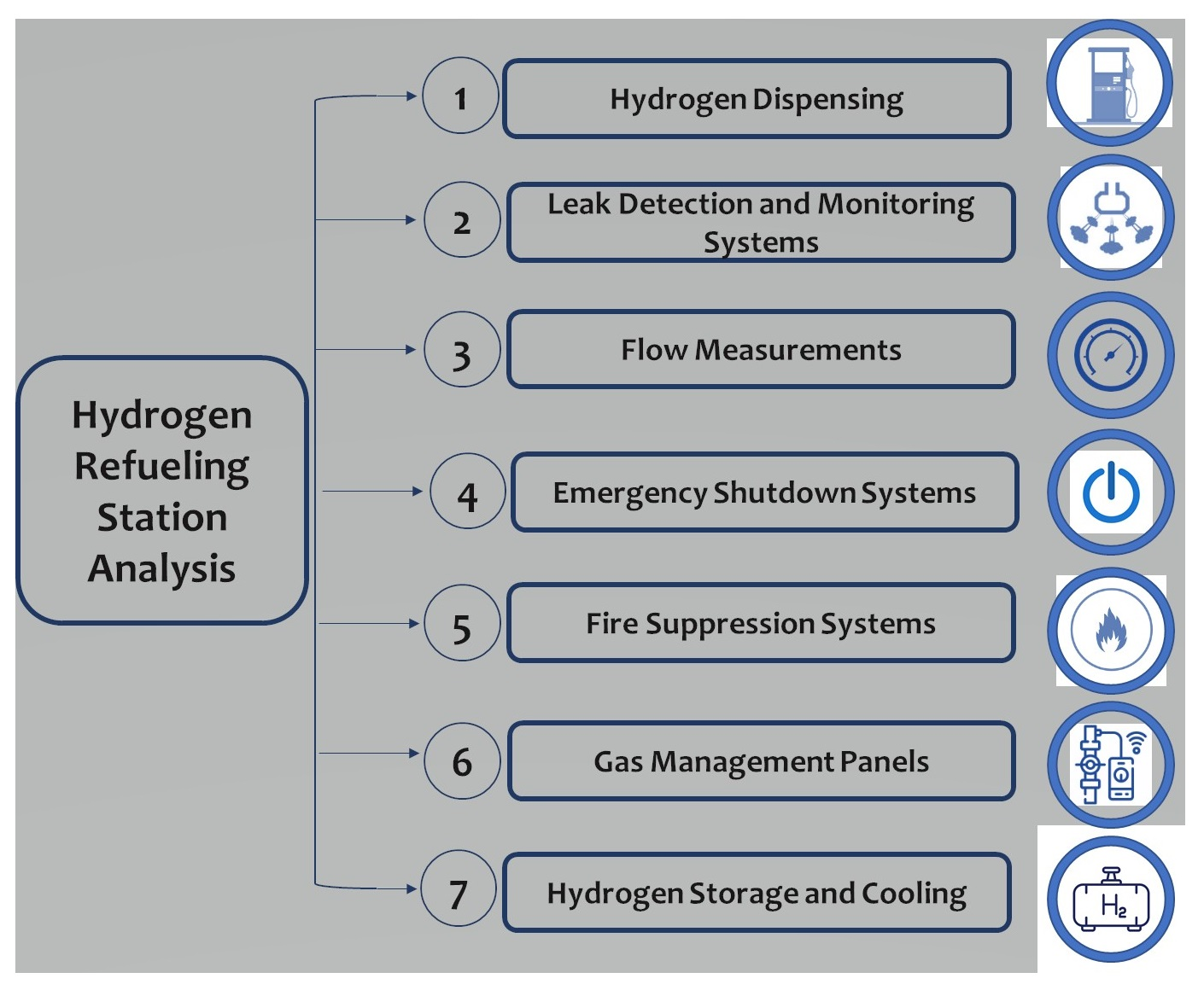
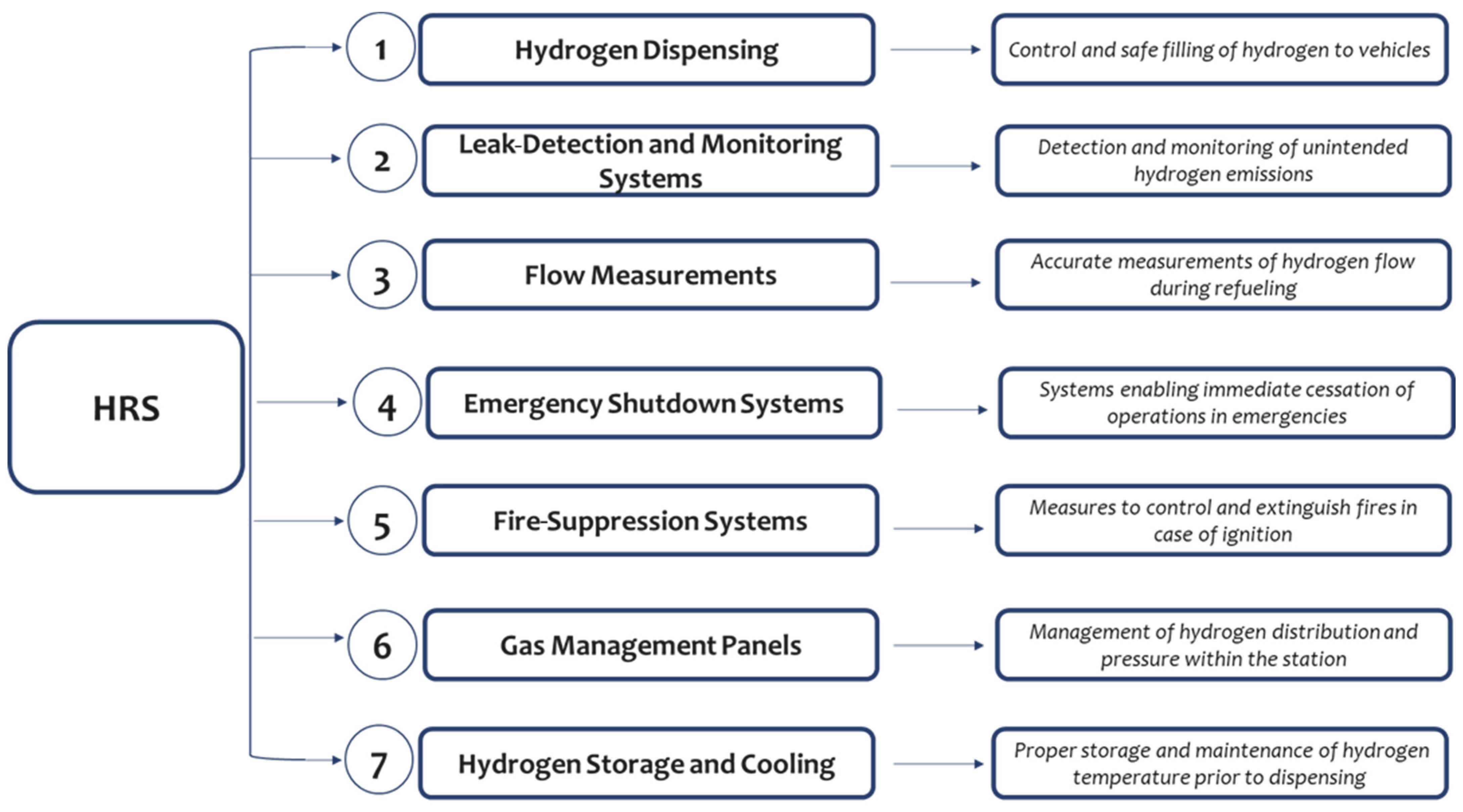
The growing recognition of hydrogen as a feasible substitute for conventional fuels has resulted in the widespread establishment of HRSs. The prioritization of operational safety inside these stations is crucial for promoting public acceptability and compliance with regulatory criteria. An extensive examination of the scholarly literature uncovers many essential safety measures and considerations that have been developed and applied throughout HRSs. The safety procedures outlined in the literature primarily focus on mitigating the occurrence of hydrogen leaks and effectively managing possible sources of ignition. The principal safety measures encompass seven main areas: hydrogen dispensing, leak-detection and monitoring systems, flow measurements, emergency shutdown systems, fire-suppression systems, gas management panels, and hydrogen storage and cooling.

3.1. Hydrogen Dispenser Design and Maintenance

Hydrogen dispensers play a crucial role in hydrogen refueling stations, as they are specifically designed with numerous safety features to accommodate the distinctive properties of hydrogen [22]. The safety of these dispensers is achieved through a sophisticated combination of factors, including the careful selection of materials, effective pressure control, precise nozzle design, the integration of advanced sensors, the incorporation of safety mechanisms such as breakaway couplings, grounding to prevent electrostatic discharge, and the use of explosion-proof components [23,24]. Every one of these characteristics plays a crucial part in guaranteeing secure refueling operations. Stainless steel is primarily utilized in construction because of its compatibility with hydrogen, which prevents chemical reactions and degradation [25]. The nozzles are intricately engineered with safety interlocks to prevent unintended hydrogen release, while integrated sensors continuously monitor crucial parameters such as temperature and pressure to guarantee operational safety. Moreover, the dispensers are outfitted with automatic shut-off valves that have a vital function in halting the flow of hydrogen in the event of malfunction, thereby substantially diminishing the likelihood of accidents [26].
Ensuring the safe operation of hydrogen dispensers is equally important to their design, making maintenance a critical aspect. Regular maintenance entails a methodical approach to examining, evaluating, and upgrading the dispensing equipment. Regular inspections need to be conducted to detect possible leaks, indications of deterioration, and any harm to vital elements such as hoses and nozzles. Pressure testing is a crucial aspect of maintenance, as it guarantees that the dispensers are capable of safely managing the high-pressure circumstances necessary for hydrogen refueling. The regular calibration of sensors and measuring instruments is performed to uphold their accuracy, which is crucial for ensuring operational safety. Ensuring the cleanliness and proper functioning of filters is crucial for preserving the purity of dispensed hydrogen. Regular inspections are conducted on electrical systems, including grounding mechanisms, to mitigate any potential hazards related to electrostatic discharges. In addition to these technical aspects, the software that manages the dispensers is regularly updated to improve their functionality and safety. In addition, maintenance personnel receive regular training to keep up with safe handling practices and emergency procedures. Maintaining comprehensive documentation of all maintenance activities is a crucial practice that aids in monitoring the condition of the dispensers over time and predicting potential problems. The main aspects of hydrogen dispenser safety are summarized in Table 1.
Pressure rating and temperature requirements are vital considerations in the design and maintenance of hydrogen dispensers, as they have a substantial impact on operational safety and efficiency. The pressure rating of hydrogen dispensers is a crucial design parameter that directly impacts their safety and functionality. Hydrogen is commonly distributed at elevated pressures to enhance the effectiveness of fueling and storage. There are two established pressure ratings for hydrogen dispensers, specifically designed to accommodate various types of vehicles. Light-duty vehicles commonly utilize dispensers with a rating of 700 bar [27], whereas heavy-duty vehicles may employ dispensers with a rating of 350 bar [28,29]. High pressures are essential for effectively compressing hydrogen to attain the desired energy density in the fuel tank of the vehicle. Dispensers are designed to effectively and securely manage these elevated pressures. This entails the development of durable pipes, hoses, and connectors that can endure the operational pressure without any leakage or malfunctions. The materials employed must uphold their structural integrity amidst these elevated pressure conditions. Safety valves and pressure relief mechanisms are essential components of dispenser design, serving to ensure safety and prevent excessive pressure buildup. These components are essential for averting excessive pressure and for safely discharging pressure in the event of system malfunctions.
Effective temperature control in hydrogen dispensers is a crucial aspect due to the unique properties of hydrogen and the thermodynamics involved in its compression and dispensing process:
  • The compression or dispensing of hydrogen can result in a substantial increase in its temperature [30]. Dispensers are designed with temperature management and control systems to ensure that the temperature increase remains within safe limits.
  • The materials utilized in the dispenser, particularly in seals and hoses, must possess the ability to endure temperature fluctuations without undergoing degradation [31]. This guarantees prolonged resilience and security.
  • The dispensers are equipped with integrated temperature sensors that offer real-time data, enabling the monitoring and control of hydrogen temperature while refueling. Ensuring safe operation is crucial, as excessively high temperatures can present safety hazards [32].
Protocols for maintenance specifically target pressure and temperature issues [33]. Hydrogen dispenser maintenance protocols involve periodic inspections and adjustments pertaining to pressure and temperature [34]. Routine pressure tests are conducted to verify that the dispenser is capable of safely withstanding its designated pressure [35]. This entails conducting inspections to detect any leaks and ensuring the appropriate operation of pressure relief valves [36,37]. The maintenance procedure involves the inspection and calibration of temperature sensors to guarantee their precise monitoring and the control of hydrogen temperature during the dispensing process. Seals and hoses, which experience strain as a result of changes in pressure and temperature, undergo regular inspections to identify any signs of wear or damage. Safety valve testing is performed periodically to verify their proper functioning during instances of excessive pressure.
It is crucial to integrate these strict pressure and temperature specifications into the design and maintenance of hydrogen dispensers to ensure the secure and effective functioning of hydrogen refueling stations. These measures aid in reducing risks related to high-pressure hydrogen fueling and guarantee adherence to pertinent safety standards and regulations [38].
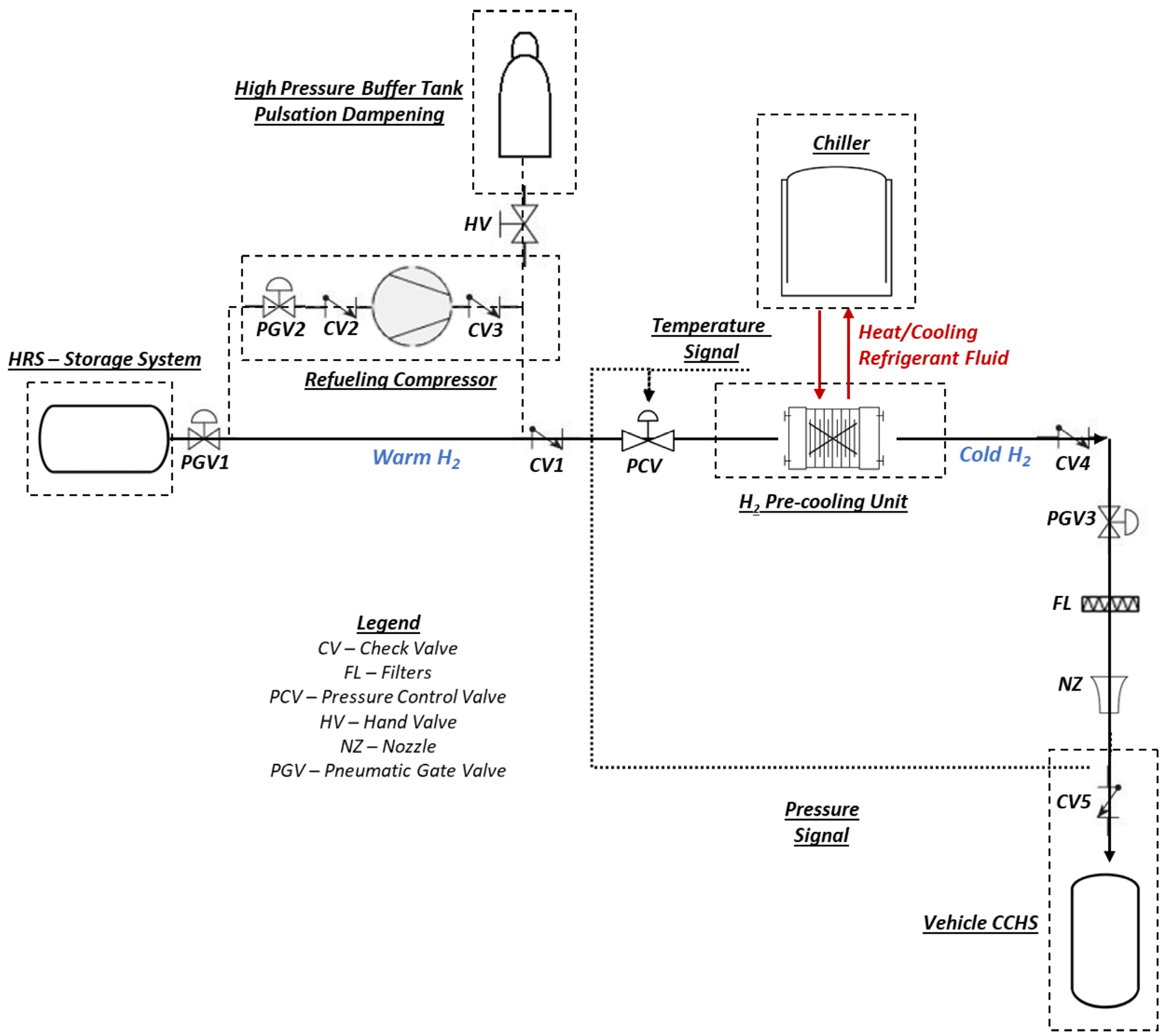
The hydrogen refueling process commences by utilizing hydrogen stored within a storage tank that operates at high pressure, as shown in Figure 4. The HRS supplies hydrogen from its main storage system, which is then transferred into the vehicle’s tank via a cascading process. If the storage pressure of the HRS is lower than that of the vehicle’s compressed hydrogen storage system (CHSS), a compressor is used to provide the necessary refueling pressure. To avoid excessive heat in the CHSS, hydrogen is subjected to a cooling process in a pre-cooling unit before entering the CHSS. The pressure control valve (PCV) is crucial for controlling the pace at which the pressure increases, which in turn affects the amount of mass flow into the vehicle’s tank.
The hydrogen is transported through high-pressure piping to the dispenser. A compressor can be employed to elevate the pressure of hydrogen. Subsequently, the pressure regulator fine-tunes the hydrogen to a suitable level for dispensing. The dispenser unit, equipped with a hose and nozzle specifically designed for safe and reliable attachment to vehicles, enables the process of refueling. The presence of safety valves, temperature and pressure sensors, and a breakaway mechanism on the hose guarantees both the safety and efficiency of the refueling process. Grounding and electrostatic discharge (ESD) protection are essential components of this process.

3.2. Leak-Detection Systems in Hydrogen Stations

Ensuring the detection of leaks in hydrogen stations is of utmost importance because hydrogen possesses a high susceptibility to catching fire and is difficult to see [40]. State-of-the-art technologies are utilized to efficiently and precisely identify leaks, thereby improving safety in these settings [41,42]. The main technology is centered around sensors capable of detecting hydrogen at extremely low concentrations [43,44,45]. These sensors function based on principles such as thermal conductivity, electrochemical reactions, and semiconductor-based detection [46,47].
Thermal conductivity sensors exploit the disparity in thermal conductivity between hydrogen and air. The sensor is capable of detecting a change in conductivity and subsequently activating an alarm when hydrogen is detected. Electrochemical sensors function by undergoing a chemical reaction with hydrogen, resulting in the generation of an electric current that is directly proportional to the concentration of hydrogen. This current serves as an indication of the existence of a leak. Conversely, sensors that rely on semiconductors exhibit alterations in their electrical resistance when hydrogen is present. The sensors are incorporated into the safety system of the station and strategically positioned in areas prone to leaks, such as in proximity to dispensers, storage tanks, and pipelines.
The efficacy of leak-detection systems in hydrogen stations can be evaluated based on various criteria, such as sensitivity, response time, and environmental adaptability:
  • The sensitivity of a leak-detection system is crucial. Hydrogen sensors must be capable of detecting extremely low levels of hydrogen in order to ensure the prompt detection of leaks. Semiconductor-based sensor systems are generally characterized by their high sensitivity, enabling them to detect hydrogen at concentrations as low as parts per million (ppm).
  • Swift detection is crucial for ensuring safety. Electrochemical sensors are renowned for their rapid response, frequently detecting hydrogen leaks within a matter of seconds. The timely identification of this prompt is crucial for implementing safety measures promptly to reduce risks.
  • Environmental adaptability is crucial for leak-detection systems, as they need to function consistently and effectively in diverse environmental circumstances. Thermal conductivity sensors are durable and less affected by changes in the environment, whereas semiconductor sensors may need frequent calibration and are more responsive to fluctuations in temperature and humidity.
The effectiveness of the sensors is also influenced by their maintenance requirements and operational lifespan. Electrochemical sensors, although they offer high sensitivity and rapid response, tend to have a shorter operational life and necessitate more frequent replacement when compared to thermal conductivity sensors. The financial implications of installing and maintaining leak-detection technology can significantly influence the decision-making process. Despite their susceptibility to environmental factors, semiconductor-based sensors are widely favored due to their cost-effectiveness in comparison to alternative types. Based on this evaluation and contrast, it is evident that no individual technology outperforms others in every aspect. However, a blend of diverse sensor types can offer a thorough and efficient system for detecting leaks in hydrogen stations. Every type adds its unique strengths, forming a complex safety mechanism that is essential for these hazardous environments, as summarized in Table 2.

3.3. Flow Measurements in Hydrogen Refueling Stations

Flow measurements in hydrogen refueling stations are crucial for accurately quantifying the fuel dispensed and maintaining safety. Precise flow measurement is crucial for monitoring and regulating the rate of hydrogen transfer, which is vital to avoid excessive pressure and ensure effective and secure refueling operations [48]. Various technologies are utilized for measuring the flow in these stations, each possessing distinct characteristics.
The Coriolis flow meter utilizes the Coriolis effect to measure the mass flow of hydrogen by detecting the impact of this effect on a vibrating tube [49,50]. The device offers exceptional precision and enables the precise measurement of mass flow, making it particularly advantageous in high-pressure settings such as hydrogen stations. An ultrasonic flow meter is a device that determines flow rate by measuring the time it takes for ultrasonic pulses to travel. These devices are unobtrusive and devoid of any mechanical components, rendering them resilient and requiring no upkeep. Nevertheless, the precision of their measurements can be affected by the physical characteristics of the gas. Electromagnetic flow meters are primarily used for measuring liquid flow, but they can also be utilized for gases as long as the gases have conductivity. Flow is quantified by assessing the voltage produced when the fluid traverses a magnetic field. The limitation of using hydrogen lies in its non-conductive nature, which poses a challenge. A differential pressure flow meter is a device that determines the rate of flow by measuring the decrease in pressure caused by an obstruction in the flow path. Although commonly employed and economically efficient, their precision can be influenced by variations in pressure and temperature.
The selection of flow measurement technology in hydrogen refueling stations is contingent upon factors such as precision, expense, and compatibility with high-pressure hydrogen environments [51,52]. Coriolis flow meters are renowned for their remarkable precision and dependability, making them the preferred option for situations where accuracy is of utmost importance. Nevertheless, they have a higher cost compared to alternative flow meters. Ultrasonic flow meters provide the benefits of being non-invasive and requiring no maintenance, although their precision may be slightly inferior in comparison to Coriolis meters. Hydrogen’s non-conductive nature makes electromagnetic flow meters less prevalent in hydrogen applications, and they typically provide moderate accuracy. Differential pressure flow meters are economical and commonly employed, although they may not provide the same degree of precision as Coriolis or ultrasonic meters, particularly under fluctuating pressure and temperature circumstances.
As shown in Table 3, Coriolis and ultrasonic flow meters are typically more precise and appropriate for hydrogen refueling stations. However, differential pressure flow meters provide a cost-effective alternative with reasonably accurate results. The selection of technology frequently involves weighing the requirement for accuracy against financial limitations and the particular demands of each hydrogen refueling station.

3.4. Emergency Shut-off Mechanisms in Hydrogen Refueling Stations

Emergency shut-off mechanisms are vital safety components in hydrogen refueling stations [53,54]. They are specifically engineered to promptly cease the flow of hydrogen in case of an emergency, such as a leak, fire, or system failure. These mechanisms are essential for mitigating potential hazards related to hydrogen, which is highly combustible and can undergo explosive reactions under specific circumstances.
The main categories of emergency shut-off mechanisms utilized in hydrogen refueling stations consist of manual emergency shut-off, automatic emergency shut-off, and breakaway couplings, as summarized in Table 4:
  • Manual emergency shut-off: This refers to a tangible system for shutting off operations, typically in the form of a button or switch, conveniently located for station operators and occasionally accessible to customers as well. Depressing this button during an emergency will promptly terminate the hydrogen supply from its source, thereby mitigating the potential hazards associated with hydrogen.
  • Automatic emergency shut-off: These systems are activated automatically by the safety systems of the station. They are triggered in reaction to particular perilous circumstances, such as sensing a hydrogen leakage, excessive pressure accumulation, or a fire. The station is equipped with sensors that detect these conditions and activate the shut-off mechanism automatically when required.
  • Breakaway couplings are installed on hydrogen hoses to securely detach the hose from the dispenser or vehicle in the event of accidental drive-offs or excessive force. This detachment effectively seals both ends of the hose, thereby preventing any hydrogen from escaping.
During an emergency, these shut-off mechanisms quickly stop the release of hydrogen, thereby minimizing the chances of ignition and explosion. The manual emergency shut-off is initiated by a human operator who manually activates the system upon identifying a dangerous situation. Automated emergency shut-off systems are significantly more advanced. They depend on sensor input to detect perilous conditions. As an illustration, when a hydrogen leak is detected, a leak-detection sensor transmits a signal to the control system, which subsequently triggers the shut-off valve. Breakaway couplings function through mechanical means. In the event that a vehicle drives away while the nozzle is still connected, the design of the coupling enables it to fracture at a predetermined location. This break is efficient and guarantees the prompt closure of both ends of the hose, halting the flow of hydrogen.

3.5. Fire-Suppression Techniques for Hydrogen Fires

Hydrogen fires pose distinct difficulties because of the gas’s elevated flammability and the imperceptible quality of the flame fire [55,56,57,58]. Specialized and highly effective fire-suppression techniques are necessary for hydrogen refueling stations. Commonly employed methods encompass water mist systems, dry chemical suppressants, and gas-based suppression systems [59,60,61].
Water mist systems are systems that release small water droplets that absorb heat and displace oxygen, effectively reducing the temperature and depriving the fire of oxygen, thus extinguishing it. Water mist systems are highly efficient in suppressing hydrogen fires by minimizing the likelihood of reignition, a prevalent concern associated with hydrogen flames. The typical dry chemicals utilized comprise powders such as monoammonium phosphate or sodium bicarbonate. These agents function by disrupting the chemical reaction of the fire. They possess high efficacy in rapidly extinguishing flames, although they may not be capable of preventing reignition in the event of hydrogen presence. Gas-based suppression systems utilize gases such as carbon dioxide or clean agents like FM-200 to either displace oxygen or hinder the chemical reactions that support the fire. Hydrogen fires are less frequent because of the potential for hydrogen to reignite and the requirement for airtight conditions for optimal effectiveness.
The efficacy of these fire-suppression methods varies depending on multiple factors, such as the severity of the fire, environmental circumstances, and the speed at which the system is deployed, as shown in Table 5.
Water mist systems are commonly favored for extinguishing hydrogen fires because they possess the capability to effectively tackle the distinctive difficulties associated with such fires, even though every fire-suppression technique has its own advantages. Nevertheless, the selection of a system is contingent upon the particular environmental circumstances and the configuration of the hydrogen refueling station. Employing various methodologies can also serve as a tactic to guarantee extensive fire extinguishment coverage [62,63,64].

3.6. Gas Management Panels

Gas management panels play a crucial role in hydrogen refueling stations, acting as central control systems for regulating the movement and force of hydrogen gas. Their responsibility in guaranteeing safety and operational efficiency is diverse and crucial for the seamless operation of these stations. This function is crucial in order to mitigate the risk of over-pressurization, which is a major hazard in the handling of hydrogen. By regulating pressure within acceptable thresholds, these panels prevent potential dangers. In addition, they are frequently incorporated into the station’s leak-detection systems. If a leak-detection alert occurs, the gas management panel can automatically activate protocols to stop the hydrogen flow, thus playing a vital role in promptly mitigating the hazard.
Gas management panels play a crucial role in emergency responses when it comes to safety. These systems are usually designed to promptly react in critical situations, such as triggering emergency shut-off valves and activating fire-suppression systems upon detecting a fire or leak. An important characteristic is the incorporation of safety interlocks. The purpose of these interlocks is to avert inadvertent or unauthorized operation, guaranteeing that hydrogen dispensing takes place solely under regulated and secure circumstances. Gas management panels regulate the flow rate of hydrogen to the dispensers on the operational front. This control is crucial not only for optimizing refueling efficiency but also for preserving the structural integrity of the vehicle’s hydrogen storage system. The panels make a substantial contribution to the station’s overall operational efficiency. They reduce hydrogen waste and guarantee efficient delivery, which is essential for the financial sustainability of the station.
Moreover, these panels frequently come with the ability to monitor and record data. They monitor and document crucial operational variables such as flow rates, pressure, and temperature [65,66]. These data are extremely valuable for regular maintenance, problem solving, and enhancing station performance. The gas management panels’ user interface is another crucial attribute. It offers operators immediate access to data and the ability to control the system in real time, which is crucial for ensuring both the safety and efficiency of station operation. As summarized in Table 6, gas management panels play a crucial role in hydrogen refueling stations by ensuring compliance with safety regulations while meeting operational needs. Their capacity to control, oversee, and react to diverse circumstances renders them essential for the secure and efficient administration of hydrogen fuel distribution.

3.7. Hydrogen Storage and Hydrogen Pre-Cooling Units

The efficiency and functionality of HRSs are greatly influenced by the design of hydrogen storage systems. Both the orientation of hydrogen storage tanks and the role of buffer tanks are pivotal in this context. The selection of either vertical or horizontal hydrogen storage tanks is contingent upon various site-specific considerations.
Vertical storage refers to the practice of storing items in a vertical position, typically using shelves or racks that are arranged vertically. This method maximizes the use of vertical space, allows for efficient organization, and is generally more space-efficient due to having a smaller footprint, making it advantageous in areas with limited space. Additionally, this method provides enhanced drainage as a result of gravitational forces, which contributes to easier upkeep and increased safety. Vertical tanks may necessitate enhanced structural reinforcement to withstand vertical forces. Tanks in a horizontal orientation are generally more accessible and easier to maintain because of their reduced height. Due to their reduced center of gravity, they exhibit greater stability. However, their larger footprint can pose constraints in specific locations. Horizontal tanks offer greater versatility in installation, particularly in situations where there is limited vertical space.
The choice between vertical and horizontal tanks is influenced by factors such as the availability of space, ease of access, structural considerations, and land costs.
Additionally, buffer tanks play a crucial role in improving the functionality of HRSs. Demand management involves the task of maintaining a stable supply of hydrogen by effectively managing the fluctuations in demand, particularly during periods of high refueling activity. Pressure maintenance is essential for sustaining the necessary dispensing pressure. Buffer tanks play a vital role in enhancing the efficiency of the refueling process, particularly for high-pressure demands [67]. Operational efficiency is enhanced by storing hydrogen at pressures that are suitable for immediate dispensing. This reduces the burden on primary compressors, thereby improving the overall efficiency and lifespan of the system. The presence of buffer tanks enables expedited refueling by minimizing the duration required to pressurize hydrogen for individual vehicles. Buffer tanks, regardless of their position, are essential for controlling variations in demand and ensuring optimal performance at HRSs. Their presence is crucial for maintaining a consistent and expedited hydrogen refueling capacity. Table 7 summarizes the role of each storage system, and it can be concluded that storage tanks are positioned based on a careful evaluation of factors such as space optimization, ease of access, and stability.
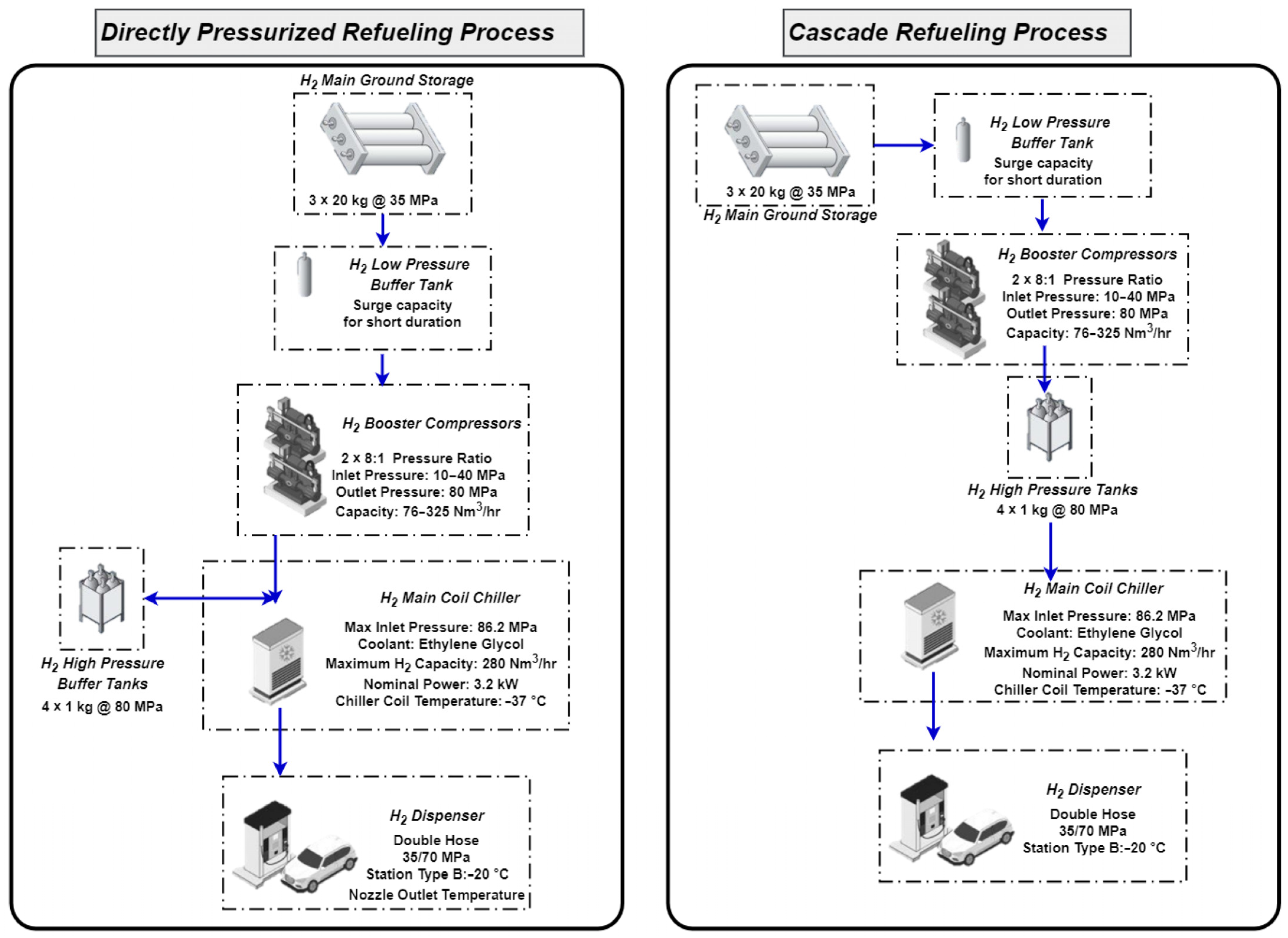
HRSs can refuel vehicles using various methods, such as directly pressurized systems with a compressor or cascade storage systems [12], as shown in Figure 5. Every method possesses unique attributes, benefits, and drawbacks, particularly in relation to achieving pulsation-free operation.
Directly pressurized refueling using a compressor for refueling provides a consistent source of hydrogen by directly increasing the pressure from storage to the vehicle. This method has the ability to scale, allowing for the accommodation of varying levels of demand. It also has the potential to incorporate larger compressors in order to achieve higher throughput. The design is relatively simple, requiring a reduced number of storage tanks and valves. Nevertheless, it can cause fluctuations in flow [67], resulting in a less seamless refueling process, and prolonged usage can lead to heightened deterioration and elevated energy usage. On the other hand, cascade storage systems offer operation without pulsation and are highly efficient in situations with high demand [69,70,71,72,73]. They achieve this by using multiple tanks to ensure a consistent pressure. This system minimizes the dependence on compressors, thereby potentially reducing the occurrence of wear and tear. However, these systems are inherently intricate because they require multiple tanks operating at varying pressure levels and advanced flow control systems. Additionally, they necessitate a larger amount of physical area and may encounter difficulties in effectively utilizing the ultimate phases of the cascade, which could result in inefficiencies.
Ultimately, the decision between a directly pressurized system and a cascade system hinges on the precise operational requirements and limitations of the HRS. Compressors provide simplicity and a constant supply, while cascade systems are particularly effective in delivering smooth operation without pulsations and high efficiency in situations with high demand. The decision frequently entails weighing these factors in relation to the availability of space, patterns of demand, and the complexity of operations. An overall comparison between these two refueling methods is presented in Table 8.
Hydrogen pre-cooling units are vital in contemporary HRSs, especially those operating at elevated pressures, such as 700 bar. The main purpose of these units is to lower the temperature of the hydrogen gas prior to its release into the fuel tank of a vehicle. The cooling process is crucial for multiple reasons:
  • The significance of hydrogen pre-cooling for temperature control during refueling lies in the fact that when hydrogen is compressed and dispensed, it undergoes a natural increase in temperature as a result of the Joule–Thomson effect. The elevated temperature resulting from this heat can significantly increase the hydrogen’s temperature, which may potentially give rise to safety concerns and diminish the efficiency of fuel transfer.
  • To ensure optimal utilization of the storage capacity, it is important to maintain fuel quality by storing cooler hydrogen, which is denser and allows for greater fuel storage within the same volume.
  • Vehicle hydrogen tanks are engineered to function within designated temperature thresholds. Pre-cooling the hydrogen is beneficial in avoiding the overheating of the vehicle’s tank while refueling.
  • Compliance with international standards, such as SAE J2601 [36], mandates specific temperature boundaries for hydrogen fuel during the process of refueling. Pre-cooling units assist in meeting these standards, guaranteeing secure and uniform refueling across various stations.
Hydrogen pre-cooling units employ a refrigeration cycle to reduce the temperature of the hydrogen gas by having a refrigerant absorb its heat. The process of heat exchange involves the passage of hydrogen gas through a heat exchanger, where it indirectly interacts with the refrigerant that is at a lower temperature. The thermal energy from the hydrogen is transferred to the refrigerant, resulting in the cooling of the hydrogen. The hydrogen’s temperature is consistently monitored to verify that it falls within the specified range prior to being introduced into the vehicle’s tank. The cooling capacity of the pre-cooling unit can be modified to accommodate various refueling conditions, such as ambient temperature or refueling speed [74,75].
Although hydrogen pre-cooling units are essential for ensuring safe and efficient refueling, they also bring about added intricacy and expenses to the hydrogen refueling station. Efficiency optimization is crucial for the design and functioning of these units, particularly with regard to energy consumption. Ensuring reliable and consistent cooling performance requires proper maintenance of the refrigeration system to keep it in optimal working condition [76]. Hydrogen pre-cooling units have undergone substantial advancements as hydrogen fueling technology progresses. These units are crucial for ensuring the safety and efficiency of hydrogen refueling, particularly under high pressures. The primary progress in this field centers on enhancing the efficiency of cooling, minimizing energy usage, and improving the reliability of the system [77]. Contemporary pre-cooling units frequently utilize sophisticated refrigeration technologies that are both more efficient and environmentally sustainable [78]. These systems may employ sophisticated refrigerants that have reduced global warming potential and enhanced heat transfer properties [79]. Advancements in heat exchanger technology have led to a substantial increase in the efficiency of pre-cooling units. Progress in materials and design enables enhanced heat transfer, which is crucial for rapidly and evenly cooling hydrogen [80,81,82,83]. Recent designs prioritize compactness and modularity, facilitating the integration of pre-cooling units into various hydrogen refueling stations, including those with limited space.
The standard temperature range for pre-cooling units in hydrogen stations is specifically engineered to lower the temperature of hydrogen gas to approximately −40 °C to −10 °C. This range is adequate to prevent excessive heating during the refueling process, particularly for high-pressure refueling at 700 bar. Advancements in design also prioritize durability of the units and ease of maintenance, guaranteeing long-term dependable functioning with minimal periods of inactivity. The primary advancements in hydrogen pre-cooling units revolve around the integration of more effective refrigeration technologies, enhancing the performance of heat exchangers, improving the adaptability of systems, and creating compact and modular designs. These advancements are designed to address the growing need for hydrogen refueling solutions that are efficient, dependable, and environmentally sustainable.
Hydrogen cooling systems at refueling stations can be classified into two types: active and passive cooling. Active cooling can be also classified into two categories: direct cooling and indirect cooling. The direct cooling technique utilizes a diffusion-bonded heat exchanger to directly decrease the temperature of the hydrogen. It is frequently utilized because of its effectiveness. Indirect cooling involves the use of a cooling medium, such as a mixture of water and glycol, to cool the hydrogen. This method is generally discouraged due to its relatively low efficiency. On the contrary, the passive cooling method involves utilizing a hydrogen heat exchanger that possesses a substantial thermal mass, thereby enabling the use of a more compact refrigeration system. It is advisable to use lower back-to-back fillings for cars.
The efficiency and suitability of each method for hydrogen refueling stations depend on specific requirements, such as the frequency of back-to-back refuelings [84] or the quantity of hydrogen dispensed per refueling. Every method possesses distinct applications and varying levels of efficiency. Direct cooling is favored due to its high efficiency in situations with high demand. Indirect cooling, although less efficient, can be employed in certain specific contexts. Passive cooling is appropriate for stations that require refueling less frequently, providing a condensed solution. To obtain a comprehensive understanding and practical implementation, it is essential to assess each technology according to the distinct needs and operational characteristics of the station. Table 9 and Table 10 summarize the features of the discussed cooling methods.

4. Conclusions

This paper has highlighted the utmost significance of safety in the rapidly changing field of hydrogen fueling technology. This study has explored multiple facets, encompassing the intricate configuration of hydrogen dispensers and resilient leak-detection systems, as well as the efficacy of emergency shut-off mechanisms and fire-suppression techniques. The research emphasized that the safety and effectiveness of hydrogen refueling stations depend greatly on the accuracy of the design and upkeep of hydrogen dispensers, as well as marked the necessity of materials and systems that can endure extreme conditions of high pressure and temperature without compromising safety. The incorporation of sophisticated leak-detection technologies is proven to be essential in promptly identifying and minimizing potential hazards, thereby improving the overall safety of these facilities.
Moreover, the study highlighted the complexity of emergency shut-off mechanisms and fire-suppression techniques. These components are essential not only for immediate hazard control but also for maintaining the integrity of the station during unexpected events. Moreover, the paper provided a perceptive summary of recent technological progress in the field. These advancements not only tackle existing safety challenges but also lay the groundwork for future advancements in hydrogen fueling infrastructure. The incorporation of advanced technologies and materials, along with the development of updated safety protocols, suggests a favorable trend toward enhanced efficiency, dependability, and safety in hydrogen refueling stations.
In conclusion, the present paper offered a thorough outlook on the safety protocols implemented in hydrogen refueling stations, emphasizing their importance in the wider effort to promote hydrogen as a sustainable and secure substitute for fuel. The findings from this research can play a crucial role in shaping the advancement of safer and more efficient hydrogen refueling infrastructures, which are essential for the expanding hydrogen economy and the global transition towards cleaner energy solutions.

Author Contributions

Conceptualization, M.G., D.B. and P.F.; methodology, M.G., D.B. and P.F.; software, M.G., D.B. and P.F.; validation, M.G., D.B. and P.F.; formal analysis, M.G., D.B. and P.F.; investigation, M.G., D.B. and P.F.; resources, M.G., D.B. and P.F.; data curation, M.G., D.B. and P.F.; writing—original draft preparation, M.G., D.B. and P.F.; writing—review and editing, M.G., D.B. and P.F.; visualization, M.G., D.B. and P.F.; supervision, M.G., D.B. and P.F.; project administration, M.G., D.B. and P.F. All authors have read and agreed to the published version of the manuscript.

Funding

This research received no external funding.

Data Availability Statement

All data and materials are available on request from the corresponding author. The data are not publicly available due to ongoing researches using a part of the data.

Conflicts of Interest

The authors declare no conflicts of interest.

References

  1. Dagdougui, H.; Sacile, R.; Bersani, C.; Ouammi, A. An Overview of Hydrogen Economy. In Hydrogen Infrastructure for Energy Applications; Academic Press: Cambridge, MA, USA, 2018. [Google Scholar]
  2. Mukelabai, M.D.; Wijayantha, U.K.G.; Blanchard, R.E. Renewable Hydrogen Economy Outlook in Africa. Renew. Sustain. Energy Rev. 2022, 167, 112705. [Google Scholar] [CrossRef]
  3. BDI Department Energy and Climate Policy. Bringing a European Hydrogen Economy to Scale. 2020. Available online: https://english.bdi.eu/publication/news/bringing-a-european-hydrogen-economy-to-scale/ (accessed on 1 December 2023).
  4. Abe, J.O.; Popoola, A.P.I.; Ajenifuja, E.; Popoola, O.M. Hydrogen Energy, Economy and Storage: Review and Recommendation. Int. J. Hydrogen Energy 2019, 44, 15072–15086. [Google Scholar] [CrossRef]
  5. Huijts, N.M.A.; Van Wee, B. The Evaluation of Hydrogen Fuel Stations by Citizens: The Interrelated Effects of Socio-Demographic, Spatial and Psychological Variables. Int. J. Hydrogen Energy 2015, 40, 10367–10381. [Google Scholar] [CrossRef]
  6. Lin, R.-H.; Ye, Z.-Z.; Wu, B.-D. A Review of Hydrogen Station Location Models. Int. J. Hydrogen Energy 2020, 45, 20176–20183. [Google Scholar] [CrossRef]
  7. Şahin, M. An Efficient Solar-Hydrogen DC-DC Buck Converter System with Sliding Mode Control. El-Cezeri Fen. Mühendislik Derg. 2019, 6, 558–570. [Google Scholar] [CrossRef]
  8. Jahangiri, M.; Mostafaeipour, A.; Rahman Habib, H.U.; Saghaei, H.; Waqar, A. Effect of Emission Penalty and Annual Interest Rate on Cogeneration of Electricity, Heat, and Hydrogen in Karachi: 3E Assessment and Sensitivity Analysis. J. Eng. 2021, 2021, 6679358. [Google Scholar] [CrossRef]
  9. Omid, M.A.; Şahin, M.E.; Cora, Ö.N. Challenges and Future Perspectives on Production, Storage Technologies, and Transportation of Hydrogen: A Review. Energy Technol. 2024, 2300997. [Google Scholar] [CrossRef]
  10. Jahangiri, M.; Rezaei, M.; Mostafaeipour, A.; Goojani, A.R.; Saghaei, H.; Hosseini Dehshiri, S.J.; Hosseini Dehshiri, S.S. Prioritization of Solar Electricity and Hydrogen Co-Production Stations Considering PV Losses and Different Types of Solar Trackers: A TOPSIS Approach. Renew. Energy 2022, 186, 889–903. [Google Scholar] [CrossRef]
  11. Wang, X.; Fu, J.; Liu, Z.; Liu, J. Review of Researches on Important Components of Hydrogen Supply Systems and Rapid Hydrogen Refueling Processes. Int. J. Hydrogen Energy 2022, 48, 1904–1929. [Google Scholar] [CrossRef]
  12. Genovese, M.; Fragiacomo, P. Hydrogen Refueling Station: Overview of the Technological Status and Research Enhancement. J. Energy Storage 2023, 61, 106758. [Google Scholar] [CrossRef]
  13. Kotowicz, J.; Węcel, D.; Jurczyk, M. Analysis of Component Operation in Power-to-Gas-to-Power Installations. Appl. Energy 2018, 216, 45–59. [Google Scholar] [CrossRef]
  14. Vidas, L.; Castro, R. Recent Developments on Hydrogen Production Technologies: State-of-the-Art Review with a Focus on Green-Electrolysis. Appl. Sci. 2021, 11, 11363. [Google Scholar] [CrossRef]
  15. Khan, T.O.; Young, M.A.; Mackinnon, C.B.; Layzell, C.B. The Techno-Economics of Hydrogen Compression. Transit. Tech. Briefs 2021, 1, 1–36. [Google Scholar]
  16. Amirante, R.; Cassone, E.; Distaso, E.; Tamburrano, P. Overview on Recent Developments in Energy Storage: Mechanical, Electrochemical and Hydrogen Technologies. Energy Convers. Manag. 2017, 132, 372–387. [Google Scholar] [CrossRef]
  17. Samsun, R.C.; Rex, M.; Antoni, L.; Stolten, D. Deployment of Fuel Cell Vehicles and Hydrogen Refueling Station Infrastructure: A Global Overview and Perspectives. Energies 2022, 15, 4975. [Google Scholar] [CrossRef]
  18. Kurtz, J.; Sprik, S.; Bradley, T.H. Review of Transportation Hydrogen Infrastructure Performance and Reliability. Int. J. Hydrogen Energy 2019, 44, 12010–12023. [Google Scholar] [CrossRef]
  19. Kurtz, J.; Sprik, S.; Peters, M.; Bradley, T.H. Retail Hydrogen Station Reliability Status and Advances. Reliab. Eng. Syst. Saf. 2020, 106823. [Google Scholar] [CrossRef]
  20. Li, L.; Manier, H.; Manier, M.A. Hydrogen Supply Chain Network Design: An Optimization-Oriented Review. Renew. Sustain. Energy Rev. 2019, 103, 342–360. [Google Scholar] [CrossRef]
  21. Li, L.; Manier, H.; Manier, M.-A. Integrated Optimization Model for Hydrogen Supply Chain Network Design and Hydrogen Fueling Station Planning. Comput. Chem. Eng. 2020, 134, 106683. [Google Scholar] [CrossRef]
  22. Zheng, J.; Zhao, L.; Ou, K.; Guo, J.; Xu, P.; Zhao, Y.; Zhang, L. Queuing-Based Approach for Optimal Dispenser Allocation to Hydrogen Refueling Stations. Int. J. Hydrogen Energy 2014, 39, 8055–8062. [Google Scholar] [CrossRef]
  23. Hirayama, M.; Shinozaki, H.; Kasai, N.; Otaki, T. Comparative Risk Study of Hydrogen and Gasoline Dispensers for Vehicles. Int. J. Hydrogen Energy 2018, 43, 12584–12594. [Google Scholar] [CrossRef]
  24. Hirayama, M.; Ito, Y.; Kamada, H.; Kasai, N.; Otaki, T. Simplified Approach to Evaluating Safety Distances for Hydrogen Vehicle Fuel Dispensers. Int. J. Hydrogen Energy 2019, 44, 18639–18647. [Google Scholar] [CrossRef]
  25. Dwivedi, S.K.; Vishwakarma, M. Hydrogen Embrittlement in Different Materials: A Review. Int. J. Hydrogen Energy 2018, 43, 21603–21616. [Google Scholar] [CrossRef]
  26. Hajji, Y.; Bouteraa, M.; Bournot, P.; Bououdina, M. Assessment of an Accidental Hydrogen Leak from a Vehicle Tank in a Confined Space. Int. J. Hydrogen Energy 2022, 47, 28710–28720. [Google Scholar] [CrossRef]
  27. Reddi, K.; Elgowainy, A.; Rustagi, N.; Gupta, E. Impact of Hydrogen SAE J2601 Fueling Methods on Fueling Time of Light-Duty Fuel Cell Electric Vehicles. Int. J. Hydrogen Energy 2017, 42, 16675–16685. [Google Scholar] [CrossRef]
  28. Klopčič, N.; Regenfelder, R.; Hafner, T.; Winkler, F.; Rasche, C.; Rink, M.; Trattner, A. Refuelling Tests of a Hydrogen Tank for Heavy-Duty Applications. Int. J. Hydrogen Energy 2024, 49, 1237–1249. [Google Scholar] [CrossRef]
  29. de las Nieves Camacho, M.; Jurburg, D.; Tanco, M. Hydrogen Fuel Cell Heavy-Duty Trucks: Review of Main Research Topics. Int. J. Hydrogen Energy 2022, 47, 29505–29525. [Google Scholar] [CrossRef]
  30. Xu, Z.; Dong, W.; Yang, K.; Zhao, Y.; He, G. Development of Efficient Hydrogen Refueling Station by Process Optimization and Control. Int. J. Hydrogen Energy 2022, 47, 23721–23730. [Google Scholar] [CrossRef]
  31. Yu, W.; Dianbo, X.; Jianmei, F.; Xueyuan, P. Research on Sealing Performance and Self-Acting Valve Reliability in High-Pressure Oil-Free Hydrogen Compressors for Hydrogen Refueling Stations. Int. J. Hydrogen Energy 2010, 35, 8063–8070. [Google Scholar] [CrossRef]
  32. Kurtz, J.; Bradley, T.; Gilleon, S. Hydrogen Station Prognostics and Health Monitoring Model. Int. J. Hydrogen Energy 2024, 49, 287–302. [Google Scholar] [CrossRef]
  33. Genovese, M.; Cigolotti, V.; Jannelli, E.; Fragiacomo, P. Current Standards and Configurations for the Permitting and Operation of Hydrogen Refueling Stations. Int. J. Hydrogen Energy 2023, 48, 19357–19371. [Google Scholar] [CrossRef]
  34. Deng, S.; Li, F.; Luo, H.; Yang, T.; Ye, F.; Chahine, R.; Xiao, J. Lumped Parameter Modeling of SAE J2601 Hydrogen Fueling Tests. Sustainability 2023, 15, 1448. [Google Scholar] [CrossRef]
  35. Schneider, J.; Meadows, G.; Mathison, S.R.; Veenstra, M.J.; Shim, J.; Immel, R.; Wistoft-Ibsen, M.; Quong, S.; Greisel, M.; McGuire, T.; et al. Validation and Sensitivity Studies for SAE J2601, the Light Duty Vehicle Hydrogen Fueling Standard. SAE Int. J. Altern. Powertrains 2014, 3, 257–309. [Google Scholar] [CrossRef]
  36. SAE J2601(2016); Fueling Protocols for Light Duty Gaseous Hydrogen Surface Vehicles. Society of Automotive Engineers (SAE): Warrendale, PA, USA, 2016.
  37. Chochlidakis, C.-G.; Rothuizen, E.D. Overall Efficiency Comparison between the Fueling Methods of SAEJ2601 Using Dynamic Simulations. Int. J. Hydrogen Energy 2020, 45, 11842–11854. [Google Scholar] [CrossRef]
  38. Bennici, M.B.; Ntnu, M. Risk Control in Hydrogen Fueling Stations. Master’s Thesis, Norwegian University of Science and Technology, Trondheim, Norway, 2023. [Google Scholar]
  39. Genovese, M.; Cigolotti, V.; Jannelli, E.; Fragiacomo, P. Hydrogen Refueling Process: Theory, Modeling, and In-Force Applications. Energies 2023, 16, 2890. [Google Scholar] [CrossRef]
  40. Sakamoto, J.; Sato, R.; Nakayama, J.; Kasai, N.; Shibutani, T.; Miyake, A. Leakage-Type-Based Analysis of Accidents Involving Hydrogen Fueling Stations in Japan and USA. Int. J. Hydrogen Energy 2016, 41, 21564–21570. [Google Scholar] [CrossRef]
  41. Hermkens, R.; Van Der Stok, E.; Valk, R.; Jansma, S. Leak Tightness of PVC Fittings with Hydrogen. 2022. Available online: https://www.netbeheernederland.nl/_upload/Files/Rapport_Leak_tightness_of_PVC_fittings_with_hydrogen_254.pdf (accessed on 1 December 2023).
  42. Yang, N.; Deng, J.; Wang, C.; Bai, Z.; Qu, J. High Pressure Hydrogen Leakage Diffusion: Research Progress. Int. J. Hydrogen Energy 2024, 50, 1029–1046. [Google Scholar] [CrossRef]
  43. Schmidt, H. Anatomy of an Incident: A Hydrogen Gas Leak Showcases the Need for Antifragile Safety Systems. J. Chem. Health Saf. 2019, 26, 36–39. [Google Scholar] [CrossRef]
  44. Zhou, C.; Yang, Z.; Chen, G.; Li, X. Optimizing Hydrogen Refueling Station Layout Based on Consequences of Leakage and Explosion Accidents. Int. J. Hydrogen Energy 2024, 54, 817–836. [Google Scholar] [CrossRef]
  45. Qian, J.; Li, X.; Gao, Z.; Jin, Z. A Numerical Study of Hydrogen Leakage and Diffusion in a Hydrogen Refueling Station. Int. J. Hydrogen Energy 2020, 45, 14428–14439. [Google Scholar] [CrossRef]
  46. Hübert, T.; Boon-Brett, L.; Palmisano, V.; Bader, M.A. Developments in Gas Sensor Technology for Hydrogen Safety. Int. J. Hydrogen Energy 2014, 39, 20474–20483. [Google Scholar] [CrossRef]
  47. Buttner, W.J.; Post, M.B.; Burgess, R.; Rivkin, C. An Overview of Hydrogen Safety Sensors and Requirements. Int. J. Hydrogen Energy 2011, 36, 2462–2470. [Google Scholar] [CrossRef]
  48. Pope, J.G.; Wright, J.D. Hydrogen Field Test Standard: Laboratory and Field Performance. Flow. Meas. Instrum. 2015, 46, 112–124. [Google Scholar] [CrossRef] [PubMed]
  49. Morioka, T. Performance Evaluation Test of Coriolis Flow Meters for Hydrogen Metering at High Pressure. Measurement 2023, 221, 113549. [Google Scholar] [CrossRef]
  50. Büker, O.; Stolt, K.; de Huu, M.; MacDonald, M.; Maury, R. Investigations on Pressure Dependence of Coriolis Mass Flow Meters Used at Hydrogen Refueling Stations. Flow. Meas. Instrum. 2020, 76, 101815. [Google Scholar] [CrossRef]
  51. Maury, R.; Auclercq, C.; Devilliers, C.; de Huu, M.; Büker, O.; MacDonald, M. Hydrogen Refuelling Station Calibration with a Traceable Gravimetric Standard. Flow. Meas. Instrum. 2020, 74, 101743. [Google Scholar] [CrossRef]
  52. de Huu, M.; Tschannen, M.; Bissig, H.; Stadelmann, P.; Büker, O.; MacDonald, M.; Maury, R.; Neuvonen, P.T.; Petter, H.T.; Rasmussen, K. Design of Gravimetric Primary Standards for Field-Testing of Hydrogen Refuelling Stations. Flow. Meas. Instrum. 2020, 73, 101747. [Google Scholar] [CrossRef]
  53. Sun, K.; Li, Z. Development of Emergency Response Strategies for Typical Accidents of Hydrogen Fuel Cell Electric Vehicles. Int. J. Hydrogen Energy 2021, 46, 37679–37696. [Google Scholar] [CrossRef]
  54. Li, H.; Welsh, R.; Morris, A. Emergency Responders’ Perceptions of Hydrogen Fuel Cell Vehicle: A Qualitative Study on the U.K. Fire and Rescue Services. Int. J. Hydrogen Energy 2021, 46, 32750–32761. [Google Scholar] [CrossRef]
  55. Makarov, D.; Shentsov, V.; Kuznetsov, M.; Molkov, V. Hydrogen Tank Rupture in Fire in the Open Atmosphere: Hazard Distance Defined by Fireball. Hydrogen 2021, 2, 134–146. [Google Scholar] [CrossRef]
  56. Molkov, V.V.; Cirrone, D.M.C.; Shentsov, V.V.; Dery, W.; Kim, W.; Makarov, D.V. Dynamics of Blast Wave and Fireball after Hydrogen Tank Rupture in a Fire in the Open Atmosphere. Int. J. Hydrogen Energy 2021, 46, 4644–4665. [Google Scholar] [CrossRef]
  57. Shentsov, V.; Kim, W.; Makarov, D.; Molkov, V. Numerical Simulations of Experimental Fireball and Blast Wave from a High-Pressure Tank Rupture in a Fire. 2016. Available online: https://pure.ulster.ac.uk/ws/portalfiles/portal/11583668/160311_BW%26FB_Shentsov-final.pdf (accessed on 1 December 2023).
  58. Kashkarov, S.; Makarov, D.; Molkov, V. Performance of Hydrogen Storage Tanks of Type IV in a Fire: Effect of the State of Charge. Hydrogen 2021, 2, 386–398. [Google Scholar] [CrossRef]
  59. Grasso, N.; Pilo, F.; Ciannelli, N.; Carcassi, M.N.; Mattei, N.; Ceccherini, F. Fire Prevention Technical Rule for Gaseous Hydrogen Transport in Pipelines. Int. J. Hydrogen Energy 2009, 34, 4675–4683. [Google Scholar] [CrossRef]
  60. Grasso, N.; Ciannelli, N.; Carcassi, M.; Ceccherini, F. Fire Prevention Technical Rule for Gaseous Hydrogen Refuelling Stations. In Proceedings of the International Conference on Hydrogen Safety, Pisa, Italy, 8–10 September 2005. [Google Scholar]
  61. Molkov, V. Hydrogen Safety Research: State-of-the-Art. In Proceedings of the 5th International Seminar on Fire and Explosion Hazards, Edinburgh, UK, 23–27 April 2007. [Google Scholar]
  62. Molkov, V. Fundamentals of Hydrogen Safety Engineering I. 2012. ISBN 9788740302264. Available online: https://www.arma.org.au/wp-content/uploads/2017/03/fundamentals-of-hydrogen-safety-engineering-i.pdf (accessed on 1 December 2023).
  63. Molkov, V. Fundamentals of Hydrogen Safety Engineering II. 2012. Available online: https://www.arma.org.au/wp-content/uploads/2017/03/fundamentals-of-hydrogen-safety-engineering-ii.pdf (accessed on 1 December 2023).
  64. Molkov, V. 4.04—Hydrogen Safety Engineering and Standards. In Comprehensive Renewable Energy, 2nd ed.; Letcher, T.M., Ed.; Elsevier: Oxford, UK, 2022; pp. 86–118. ISBN 978-0-12-819734-9. [Google Scholar]
  65. Genovese, M.; Blekhman, D.; Dray, M.; Fragiacomo, P. Hydrogen Losses in Fueling Station Operation. J. Clean. Prod. 2020, 248, 119266. [Google Scholar] [CrossRef]
  66. Genovese, M.; Blekhman, D.; Dray, M.; Fragiacomo, P. Multi-Year Energy Performance Data for an Electrolysis-Based Hydrogen Refueling Station. Int. J. Hydrogen Energy 2024, 52, 688–704. [Google Scholar] [CrossRef]
  67. Genovese, M.; Blekhman, D.; Xie, C.; Dray, M.; Fragiacomo, P. Assuring Pulsation-Free Flow in a Directly Pressurized Fuel Delivery at a Retail Hydrogen Station. Int. J. Hydrogen Energy 2018, 43, 16623–16637. [Google Scholar] [CrossRef]
  68. Genovese, M.; Blekhman, D.; Dray, M.; Piraino, F.; Fragiacomo, P. Experimental Comparison of Hydrogen Refueling with Directly Pressurized vs. Cascade Method. Energies 2023, 16, 5749. [Google Scholar] [CrossRef]
  69. Rogié, B.; Wen, C.; Kærn, M.R.; Rothuizen, E. Optimisation of the Fuelling of Hydrogen Vehicles Using Cascade Systems and Ejectors. Int. J. Hydrogen Energy 2021, 46, 9567–9579. [Google Scholar] [CrossRef]
  70. Sadi, M.; Deymi-Dashtebayaz, M. Hydrogen Refueling Process from the Buffer and the Cascade Storage Banks to HV Cylinder. Int. J. Hydrogen Energy 2019, 44, 18496–18504. [Google Scholar] [CrossRef]
  71. Oh, J.; Yoo, S.; Chae, C.; Shin, D. Dynamic Simulation and Optimization of Hydrogen Fueling Operated by N-Bank Cascade Fueling Method. Int. J. Hydrogen Energy 2024, 49, 276–286. [Google Scholar] [CrossRef]
  72. Yu, Y.; Lu, C.; Ye, S.; Hua, Z.; Gu, C. Optimization on Volume Ratio of Three-Stage Cascade Storage System in Hydrogen Refueling Stations. Int. J. Hydrogen Energy 2022, 47, 13430–13441. [Google Scholar] [CrossRef]
  73. Park, B.H.; Joe, C.H. Investigation of Configuration on Multi-Tank Cascade System at Hydrogen Refueling Stations with Mass Flow Rate. Int. J. Hydrogen Energy 2024, 49, 1140–1153. [Google Scholar] [CrossRef]
  74. Sadiq, M.; Saeed, M.; Mayyas, A.T.; Mezher, T.; El Fadel, M. Pre-Cooling Systems for Hydrogen Fueling Stations: Techno-Economic Analysis for Scaled Enactment. Energy Convers. Manag. X 2023, 18, 100369. [Google Scholar] [CrossRef]
  75. Elgowainy, A.; Reddi, K.; Lee, D.-Y.; Rustagi, N.; Gupta, E. Techno-Economic and Thermodynamic Analysis of Pre-Cooling Systems at Gaseous Hydrogen Refueling Stations. Int. J. Hydrogen Energy 2017, 42, 29067–29079. [Google Scholar] [CrossRef]
  76. Wu, Y.; Guo, Y.; Yu, H.; Chen, J.; Shao, S. Energetic Assessment on a Dual-Temperature Evaporation Refrigeration System for Hydrogen Pre-Cooling. Int. J. Refrig. 2024, 159, 264–275. [Google Scholar] [CrossRef]
  77. Luo, H.; Xiao, J.; Bénard, P.; Chahine, R.; Yang, T. Multi-Objective Optimization of Cascade Storage System in Hydrogen Refuelling Station for Minimum Cooling Energy and Maximum State of Charge. Int. J. Hydrogen Energy 2022, 47, 10963–10975. [Google Scholar] [CrossRef]
  78. Elgowainy, A.; Reddi, K. Hydrogen Fueling Station. Pre-Cooling Analysis. In Proceedings of the 2016 DOE Hydrogen and Fuel Cells Program Annual Merit Review, Washington, DC, USA, 6–10 June 2016. [Google Scholar]
  79. Li, S.; Guo, J.; Lv, X.; Deng, T.; Cao, B.; Wang, J. Research on High-Pressure Hydrogen Pre-Cooling Based on CFD Technology in Fast Filling Process. Processes 2021, 9, 2208. [Google Scholar] [CrossRef]
  80. Xu, W.; Yu, Z.; Mu, Q.; Peng, B.; Li, Q. Study of an Integrated Vortex Tube Used in Hydrogen Pre-Cooling System. Int. J. Hydrogen Energy 2024, 54, 971–978. [Google Scholar] [CrossRef]
  81. Piraino, F.; Blekhman, D.; Dray, M.; Fragiacomo, P. Empirically Verified Analysis of Dual Pre-Cooling System for Hydrogen Refuelling Station. Renew. Energy 2021, 163, 1612–1625. [Google Scholar] [CrossRef]
  82. Genovese, M.; Blekhman, D.; Dray, M.; Fragiacomo, P. Improving Chiller Performance and Energy Efficiency in Hydrogen Station Operation by Tuning the Auxiliary Cooling. Int. J. Hydrogen Energy 2022, 47, 2532–2546. [Google Scholar] [CrossRef]
  83. Jensen, J.K.; Rothuizen, E.D.; Markussen, W.B. Exergoeconomic Optimization of Coaxial Tube Evaporators for Cooling of High Pressure Gaseous Hydrogen during Vehicle Fuelling. Energy Convers. Manag. 2014, 85, 740–749. [Google Scholar] [CrossRef]
  84. Genovese, M.; Blekhman, D.; Dray, M.; Fragiacomo, P. Hydrogen Station in Situ Back-to-Back Fueling Data for Design and Modeling. J. Clean. Prod. 2021, 329, 129737. [Google Scholar] [CrossRef]
Figure 1. Hydrogen refueling stations in the world at the end of 2020.
Hydrogen 05 00007 g001
Figure 2. Literature review in Scopus database.
Hydrogen 05 00007 g002
Figure 3. Main areas of interest found in the literature review process.
Hydrogen 05 00007 g003
Figure 4. Schematic representation of hydrogen refueling process [39].
Hydrogen 05 00007 g004
Figure 5. Schematic representation of directly pressurized refueling process and cascade refueling process [68].
Hydrogen 05 00007 g005
Table 1. Key aspects of hydrogen dispenser safety.
AspectDescription
Material selectionUse of hydrogen-compatible materials like stainless steel to prevent chemical reactions.
Pressure managementDesign to handle high-pressure hydrogen safely.
Nozzle designSafety interlocks to prevent accidental hydrogen release.
Sensor integrationMonitoring of temperature, pressure, and flow rate for safety.
Safety mechanismsBreakaway couplings and automatic shut-off valves for emergency situations.
Grounding and ESD ProtectionPrevention of electrostatic discharge to avoid ignition risks.
Explosion-proof componentsEnsuring electrical components do not cause sparks.
Regular inspectionsChecking for leaks, wear, and damage.
Pressure testingEnsuring dispensers can handle operational pressures.
CalibrationMaintaining accuracy of sensors and instruments.
Filter maintenanceRegular cleaning/replacement for hydrogen purity.
Electrical system checksInspecting grounding and electrical components.
Software updatesEnhancing dispenser functionality and safety.
Personnel trainingEquipping maintenance staff with up-to-date safety knowledge.
Record keepingDetailed documentation of maintenance activities for tracking dispenser health.
Table 2. Comparison of leak-detection technologies.
TechnologySensitivityResponse TimeEnvironmental AdaptabilityMaintenanceCost Effectiveness
Thermal ConductivityModerate
(500 ppm—4%)
Moderate (<15 s)HighLowModerate
ElectrochemicalModerate
(up to 4%)
Moderate (<30 s)ModerateModerateHigh
SemiconductorHigh
(1 ppm—2%)
Fast (<2 s)LowHighLow
Table 3. Comparison of flow measurement technologies.
TechnologyAccuracySuitability for HydrogenCost
Coriolis Flow MeterVery HighExcellentHigh
Ultrasonic Flow MeterHighGoodModerate
Electromagnetic Flow MeterModerateLimitedModerate
Differential Pressure Flow MeterModerateGoodLow
Table 4. Comparison of emergency shut-off mechanisms.
Mechanism TypeActivation MethodPrimary FunctionSpeed of Activation
Manual Emergency Shut-offHuman-operatedCuts off hydrogen supply manuallyImmediate upon activation
Automatic Emergency Shut-offSensor-triggeredAutomatically cuts off supply in hazardous conditionsImmediate upon detection of hazard
Breakaway CouplingsMechanically triggered (e.g., by force)Seals hose ends upon accidental detachmentInstantaneous upon exceeding force threshold
Table 5. Comparison of fire-suppression techniques.
TechniqueEffectivenessSuitable EnvironmentsLimitations
Water Mist SystemsHighEnclosed and open areasDependent on water supply, less effective in windy conditions
Dry Chemical SuppressantsModerate to HighOpen and accessible areasVisibility reduction, does not prevent reignition
Gas-Based SystemsModerateEnclosed areasLimited in open environments, does not cool the area
Table 6. Gas management panels’ role in safety and operation.
AspectRole in SafetyRole in Operation
Pressure Regulation and MonitoringPrevents over-pressurization to avert potential hazards, ensuring that hydrogen is maintained within safe pressure limits.Ensures hydrogen is delivered at the correct pressure for efficient refueling and maintaining vehicle hydrogen storage system integrity.
Leak-Detection IntegrationAutomatically shuts off hydrogen flow in response to leak detection, mitigating risk of fire or explosion.Minimizes operational disruptions and potential wastage of hydrogen due to leaks.
Emergency ResponseActivates emergency shut-off valves and fire-suppression systems during emergencies, such as detected leaks or fires.Maintains operational integrity and prevents escalation of emergency situations.
Safety InterlocksPrevents accidental or unauthorized operation, ensuring hydrogen is dispensed only under safe conditions.Ensures controlled dispensing, aligning with operational protocols and standards.
Flow ControlPrimarily an operational traitRegulates the flow rate of hydrogen to dispensers for efficient refueling.
Data Monitoring and LoggingFacilitates safety audits and incident analysis through recorded data.Provides valuable information for station maintenance, troubleshooting, and performance optimization.
User InterfaceAllows operators to monitor safety parameters and respond quickly to any safety alerts.Provides real-time control and data to operators for efficient management of the station.
Table 7. Hydrogen storage systems at HRSs.
Storage SystemAdvantagesConsiderations
Vertical Storage TanksSpace-efficient, better drainageRequire robust structural support
Horizontal Storage TanksEasier access and maintenance, more stableRequire more ground space
Buffer TanksThey balance demand, maintain pressure, and enhance efficiencyEssential for rapid refueling and operational consistency
Table 8. Comparison table: directly pressurized vs. cascade system.
AspectDirectly Pressurized with CompressorCascade System
PulsationCan introduce pulsationsProvides pulsation-free operation
Design ComplexitySimpler designMore complex with multiple tanks
MaintenanceHigher, due to compressor wearLower, less reliance on compressors
Energy EfficiencyLess energy-efficientMore efficient in high-demand scenarios
ScalabilityEasily scalableRequires additional tanks for scaling up
Space RequirementLess space-intensiveRequires more space for multiple tanks
Consistency of SupplyContinuous supplySteady supply, efficient for peak demand
Table 9. Comparison table of hydrogen cooling methods.
TechnologyDescription
Direct CoolingUses a diffusion-bonded heat exchanger to cool hydrogen directly. It is efficient and common in modern systems, and especially suitable for high-volume refueling scenarios.
Indirect CoolingEmploys a cooling medium, like water/glycol, to indirectly cool hydrogen. It is generally less efficient and not recommended for most applications.
Passive CoolingUtilizes a hydrogen heat exchanger with high thermal mass, reducing the size of the refrigeration system. Recommended for stations with low back-to-back fillings.
Table 10. Key performance indicators (KPIs) of hydrogen cooling methods.
KPIsDirect CoolingIndirect CoolingPassive Cooling
Size of Heat ExchangerCompact Larger due to additional glycol cycleModerate
Size of Chiller SystemLargeLargestSmallest
Energy ConsumptionModerateHighLow
Connection LoadHighHigherLower
CAPEXModerateHighLower
Back-to-Back Fillings RateHighModerateLow
Cooling SystemEfficient for high demandSuitable for special applicationsIdeal for fewer fillings
Disclaimer/Publisher’s Note: The statements, opinions and data contained in all publications are solely those of the individual author(s) and contributor(s) and not of MDPI and/or the editor(s). MDPI and/or the editor(s) disclaim responsibility for any injury to people or property resulting from any ideas, methods, instructions or products referred to in the content.

