Review

Hydrogen from Waste Gasification

by
Reinhard Rauch
1,*,
Yohannes Kiros
2,
Klas Engvall
2,
Efthymios Kantarelis
2,
Paulo Brito
3,
Catarina Nobre
3,
Santa Margarida Santos
3 and
Philipp A. Graefe
1
1
Engler-Bunte-Insitut, Karlsruhe Institute of Technology (KIT), Engler-Bunte-Ring 1, 76131 Karlsruhe, Germany
2
Department of Chemical Engineering, KTH Royal Institute of Technology, Teknikringen 42, SE-10044 Stockholm, Sweden
3
VALORIZA—Research Center for Endogenous Resource Valorization, Campus Politécnico, 10, 7300-555 Portalegre, Portugal
*
Author to whom correspondence should be addressed.
Hydrogen 2024, 5(1), 70-101; https://doi.org/10.3390/hydrogen5010006
Submission received: 8 January 2024 / Revised: 31 January 2024 / Accepted: 8 February 2024 / Published: 10 February 2024

Abstract

:
Hydrogen is a versatile energy vector for a plethora of applications; nevertheless, its production from waste/residues is often overlooked. Gasification and subsequent conversion of the raw synthesis gas to hydrogen are an attractive alternative to produce renewable hydrogen. In this paper, recent developments in R&D on waste gasification (municipal solid waste, tires, plastic waste) are summarised, and an overview about suitable gasification processes is given. A literature survey indicated that a broad span of hydrogen relates to productivity depending on the feedstock, ranging from 15 to 300 g H2/kg of feedstock. Suitable gas treatment (upgrading and separation) is also covered, presenting both direct and indirect (chemical looping) concepts. Hydrogen production via gasification offers a high productivity potential. However, regulations, like frame conditions or subsidies, are necessary to bring the technology into the market.

1. Introduction

Environmentally benign fuels, which can replace today’s fossil-based fuels, such as oil, natural gas, and coal for combustion, either in stationary or traction applications, are of the utmost importance. One such fuel is hydrogen, which is the fuel of the future. Hydrogen is an energy carrier and energy storage medium, maintaining potential applications in many industrial processes and power generations. Hydrogen has gained momentum in recent years as a potential fuel for aviation, vehicles, and domestic heating requirements, either by direct combustion or in so-called “cold combustion” in fuel cells to realize a sustainable world. The introduction of hydrogen in our societies would mean a paradigm shift in the use renewable energy sources, leading principally to the decarbonization of the energy sector and ecosystem and, hence, a substantial decrease in greenhouse gases. Owing to its abundance bound in the form of compounds and complexes, it is estimated that over 75% of the mass of the universe is primarily hydrogen [1]. The combustion product of hydrogen practically being water makes it strategically important for clean and sustainable energy production. The calorific value for hydrogen combustion is 120 MJ/kg (LHV), showing its superior quality compared to gasoline [2]. However, currently, 96% of the global hydrogen production relies mainly on industrial processes derived from fossil fuel feedstocks [3]. Biomass with its huge sources and diverse compositions, waste products, and water have been considered as an alternative source of hydrogen production by thermolysis, biolysis, photolysis, and electrolysis. Hydrogen produced by valorization of waste materials provides both a clean energy vector and sustainable waste management compared to landfill and incineration methods [4]. Thus, waste-to-energy (WtE) and/or waste-to-hydrogen (WtH) processes or syngas have the potential to be utilized as a reliable transition from fossil fuel, globally emitting 900 Mt CO2 associated with hydrogen production [5]. Currently, there are several different “colors” of hydrogen, which give the production pathway and, indirectly, the sustainability of the produced hydrogen. They are summarised in Table 1. Hydrogen from waste does not have its own color but can be classified as green hydrogen.
Waste management, as one of the most crucial societal challenges with the ever-growing discharge of municipal solid waste (MSW), waste products from industries, agroresidues, sewage sludge, and animal manure, is closely related to welfare, hygiene, health, and bionomical issues. With the global surge of population, economic development, and standard of living, there is a remarkable increase in and disposal of MSW from cities and towns, plastics, and tires, with enormous impacts on health, economy, and environment.Thus, annual generation and production increased to 2.01 billion tons of global waste and 460 million tons of plastic in 2019 [6,7]. A significant volume of these waste products is poorly managed and ends up in landfills, leading to the resistance of biological and chemical degradation or emission of leachate and gases as well as the requirement of huge acreages with large-scale environmental concerns. At the global scale, only a quarter of the MSW, 15 wt% of plastics, and 17 MT of tires were collected and recycled for the respective years, showing the magnitude of waste management [7,8]. Though waste with its inhomogeneity is composed of biodegradable and non-degradable contents, its organic fraction as an economic and renewable resource has great potential for energy recovery technologies in the form of heat, power, and chemicals. EU Directive 2008/98/EC establishes a legal framework of waste hierarchy for (i) prevention, (ii) reuse, (iii) recycling, (iv) recovery (energy, etc.), and (v) disposal in a bid to protect the environment and human health. Therefore, appropriate policy measures and interventions are key roadmaps for the utilization of waste as useful and sustainable fuel and products with considerable effects on the circular economy and, at the same time, decreasing the negative role on living organisms and the environment.
Biomass and its derivatives in the form of organic waste are readily converted to their final products by a set of different technologies, including mechanical, chemical, biochemical, and thermochemical processes. Among these, thermochemical methods by combustion, pyrolysis, gasification, and liquefaction have gained increased attention for the conversion of biomass and waste, with a high proportion of hydrocarbon content in renewable fuel for energy and product retrieval [9,10,11,12,13,14,15]. These technologies differ substantially in reactor configurations, particle size of feedstock, heating rate, residence time, type and yield of product, reactor temperature intervals and pressures, product treatment and enrichment, type of reactant, and use of catalyst. Although the combustion of biomass and solid waste to CO2 and H2O has shown to effectively reduce the mass and volume of the MSW by 80–95% to be used in power and heat generations, it is essentially associated with emissions of toxic substances, such as furans, dioxins, NOx, SOx, and particulate matter, compared to gasification [16,17,18]. The pyrolysis and gasification of wastes (municipal, tires and plastics) are among the most mature technologies, showing different reaction products and operating at different temperatures, as shown in Figure 1.
Although gasification is a mature technology with large-capacity plants generating syngas/fuel gas in many countries [12], its successful implementation for the production of WtH or syngas as an alternative and renewable fuel is closely related to the release of byproducts, such as ash, sulfur, alkali metals, particulates, and tar, and the subsequent product cleanup systems. Tar as condensable organic molecules is especially challenging, affecting operational and environmental problems during gasification by settling in filters and downstream flow in equipment, resulting in interruptions [19,20,21]. Different approaches for the containment of tars and related byproducts are used in the form of physical, thermal, and catalytic processes for achieving high-purity hydrogen and/or syngas. The present work focuses on the available literature for the generation of hydrogen, i.e., waste to hydrogen (WtH) or syngas, as a valuable source replacing the current fossil fuel-based production. It is a primary aim of this coverage not only to dwell on municipal waste but also on plastics and tires by implementing the gasification technology for conversion and valorization of the waste products generated in huge amounts as renewable sources for sustainable energy use. Although plasma gasification has been shown to be a viable technology to convert MSW, plastics, and rubber with various challenges remaining to be addressed [22], the focus of this review is mainly on conventional gasification technologies.

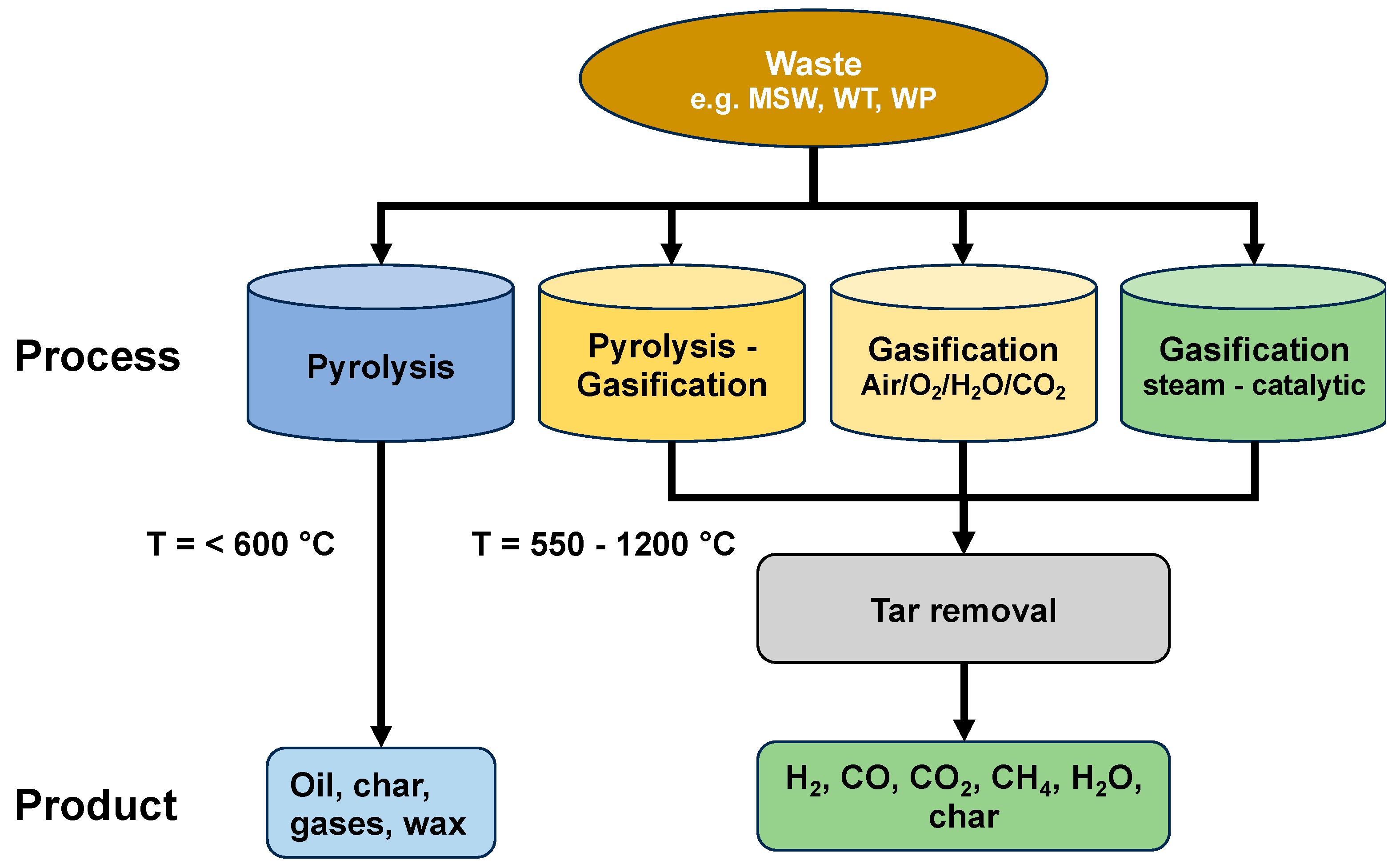
2. Gasification to produce Hydrogen from Waste

2.1. Gasification Basics

Gasification is a process where solid carbonaceous materials are converted to combustible gases (H2, CO, CH4, and CO2) in a reaction with a co-reactant (gasification agent/medium) in a temperature range of 550–1000 °C [23]. However, byproducts of tar as a mixture of high-molecular-weight aromatic and oxygenated hydrocarbons, C2–C3 hydrocarbons, solid residues of char, ash with metals, and minerals are formed [19,20,23]. Depending on the gasifying agent, the producer gas heating values can vary significantly, being 4–7 MJ/Nm3 for air due to dilution with nitrogen, 10–12 MJ/Nm3 for pure oxygen, and 15–20 MJ/Nm3 for steam [13]. CO2 is also used as an agent for gasification and has resulted in reduced energy input to the reactor with efficient gasification of the solid fuel [23,24]. The product gas can be upgraded to a syngas (mainly, CO and H2 but sometimes also CO2) used for synthesis processes or further upgraded to, e.g., pure hydrogen gas.
The gasification of biomass and solid waste occurs often not delineated in a reactor through a set of complex endothermic and exothermic reactions, consisting of (i) dehydration by drying the biomass with its inherent moisture, (ii) pyrolysis (thermal decomposition) in the absence of oxidant, (iii) partial oxidation or gasification, and (iv) reduction zone [25]. The set of complex heterogeneous and homogeneous reactions is shown in Table 2 [18,26]. Gasification involves reactions with different phases, such as gas–liquid, gas–solid, liquid–solid, and gas–gas, where diverse phenomena such as chemical reactions and transport phenomena (heat, mass and momentum transfer) between the gasification agent and feedstock take place.
In most processes for increased hydrogen or syngas production, steam is the most preferred gasifying agent for increased hydrogen or syngas production, albeit the energy requirement is high, as shown by Equations (6) (reverse), (10), and (12). In Table 2, the oxidation (1, 2, 5, 8, and 9) and methanation (3) reactions are exothermic, implying that reactor temperatures beyond 900 °C can maintain the autothermal reactions of the gaseous products within the reactor regime, validating Le Chatelier’s principle of favorable reactants and products in exothermic and endothermic reactions, respectively. Steam addition as an agent allows the tars to react via steam reforming, as shown in Equation (13). Tars can also decompose by increasing the equivalence ratio (ER-oxygen used for gasification), higher temperatures, and gas residence time as well as by using catalysts for higher-purity hydrogen or syngas production.

2.2. Gasification Research on Waste to Hydrogen

To increase the combustible part and, thus, also the energy content, unsorted waste such as MSW passes a mechanical and biological treatment installation (MBT) to recover recyclable materials separating inert and wet organic wastes to a fuel termed RDF (refuse-derived fuel). There is, however, no quality requirement for RDF, and, therefore, the gasification research presented below is for MSW. As special waste types, tires and waste plastics are also included [14,27,28].

2.2.1. Municipal Solid Waste

MSW with typical physical compositions varies significantly according to geographical location, socioeconomic factors, and society, where more than half of the organic waste is generated across all regions, except for Europe, Central America, and North America having higher portions of dry waste [6]. These waste products contain different combustible materials with high energy content, including polymeric materials, rubber, cardboard, paper, textiles, food waste, and biomass as their main components [14,29]. The physicochemical characterizations by proximate and ultimate analyses of various studies [22,27,29,30,31,32,33,34,35] according to standard methods are presented in Table 3 showing the non-uniformity of the MSW samples, deriving from various proportions of the residual source.
The status of MSW in gasification technology is mostly used for CHP, power, fuel gases, and biofuels, except for hydrogen generation from plastics by Showa Denko in Japan [12]. MSW gasification technology to produce hydrogen has been researched in various studies looking into different reactor configurations and process parameters, such as temperatures, gasifying agents with or without co-mixtures, particle sizes, heating rate, and residence time.
The moisture content is usually removed by heating at temperatures above 100 °C as this influences the overall calorific value of the feedstock and must be suppressed for increasing the conversion efficiency. However, the presence of high moisture content without a high input of steam is regarded as beneficial for in situ downstream gasification and hydrogen and syngas production [37,38]. The volatile matter is an indication of the formation of syngas (CO, H2, CH4, CO2), H2O, and tar after the devolatilization step in the pyrolysis zone [39]. The fixed carbon or char and total carbon originate with more than half as biogenic and the rest as fossil-based, which together with hydrogen defines the usable heating value of the fuel, while the fuel reactivity of the fuel increases with the contents of hydrogen and oxygen [40,41]. The fuel during gasification has an ash content related to the fuel quality and the quantity of the volatile matter along with the presence of inorganic materials. The oxygen contained in the fuel is part of the gasification process and, as such, also defines the important parameter of the equivalence ratio (ER) (actual air/fuel ratio to the stoichiometric air/fuel ratio) for syngas production. The mass fraction of hydrogen has high relevance regarding hydrogen production, as 6–7 wt% in biomass is equivalent to 0.67–0.90 Nm3 gaseous hydrogen in 1 kg biomass [42,43]. Thus, any increment or reduction in the fuel hydrogen content in MSW or any waste influences the yield of hydrogen gas and/or syngas.
A summary of operating process conditions with the respective gasifier type and hydrogen and CO production of MSW is given in Table 4. Most experiments were performed at bench-scale, from micro to batch level fixed-bed reactors, except a few with a continuous fluidized bed and pilot plant, with a feed capacity of feedstock at 100 kg/h. Steam gasification has shown increased H2 concentration and yield (g/kg MSW), primarily due to the set of gas-phase reactions involving Equations (5), reverse (6), (10), (12), and (14). Higher temperatures would also entail the discharge of H2 of the rather hard-to-crack endothermic reactions of char and tars, with high carbon conversion efficiency [44]. Thus, the increase in the syngas yields of H2 and CO as a building block for the application in chemical processes from an indigenous resource of municipal solid waste as a fuel source has significant bearing capacity. This applies to improving pollution in cities by ‘green’ strategies across societies by mitigating climate change, increasing national revenues through the introduction of innovative technologies, replacement of fossil-derived fuels and independency from unstable regions, and insecurity on energy supply. The implementation of gasification technology on MSW by harnessing H2 production fulfils the bulk of the UN 2030 Agenda for Sustainable Development.
Ma et al. [32] studied MSW by varying the temperature in a range of 700–900 °C, ER 0.2 to 0.3, and residence time of 10 to 30 min and found out that the maximum yield of H2 was 41.36 mol% (~32 g/kg MSW) in conditions of 757.7 °C, 0.241, and 22.26 min for temperature, ER, and residence time, respectively. This study was based on response surface methodology (RSM) as central composite design (CCD) to optimize the effect of process variables on the final product. Ying et al. [30] varied temperatures at 1000–1100 °C and the CO2/steam ratio in a range of 0.5–3, with the CO2 derived from gasification and reused. The experiments showed that the Boudouard reaction (Equation (7)) dominates above 700 °C, where CO2 reacts with the solid char to produce CO. An optimal CO2/steam ratio of 2.5 at 1000 °C resulted in a H2 yield of 37.7 g/kg MSW and 338.9 g/kg MSW of CO. Seo et al. [27] carried out a comparative study of gasifiers with downdraft fixed bed (DFB) and bubbling fluidized bed (BFB) performed in terms of ER in a range of 0.2 to 0.6, gas yield, and composition as well as the important parameters of carbon conversion efficiency (CCE) and cold gas efficiency (CGE). CGE is expressed as total reacted carbon in the system (kg)/total carbon fed into the system and CCE as LHV of fuel gas × fuel gas production/LHV feed [31,49]. The results obtained in BFB showed a higher syngas composition of 72.53 mol% (H2 + CO), 63.70% CCE, and 67.31% CGE at ER 0.4 and at 900 °C. Ma et al. [27] utilized experimental validation using statistical methods to analyze the effects of temperatures (700, 800, 900 °C), particle sizes in mm (1, 2.5, 3.5), and heating rates in °C/min (5, 1, 15). They were able to obtain optimum H2 production of 45.8 mol% with H2 + CO of 72.8 mol% with lower tar and char contents at 703.49 °C, particle size of 3.21 mm, and a heating rate of 5 °C/min. The H2 production rate was believed to increase with the reaction temperatures from 700 to 900 °C by both steam-reforming (reverse Equation (6)) and water-gas shift (WGS) (Equation (5)) and the endothermic reaction of Equations (8) and (10). Campoy et al. [36] compared various wastes (orujillo, meat, and bone meal, dried sewage sludge (DSS) and MSW) in a 100 kWth fluidized-bed pilot plant and showed that the H2 content of MSW was greater than the other wastes, depending on process parameters.
One of the approaches receiving increased attention without the need for increased temperature, displaying selectivity for tar removal by catalytic cracking, steam reforming of hydrocarbons, and absorption of byproducts during gasification of MSW, is catalysts and sorbents. He et al. [31] studied steam gasification of MSW in a bench-scale downstream fixed-bed reactor, using a calcined dolomite (CaMg(CO3)2) as a catalyst. The tar decomposition was complete at a temperature of 950 °C with a H2 yield of 77.3 g/kg MSW but achieved a maximum potential yield of 140.4 g H2/kg MSW at 900 °C. This high yield was attributed to the catalytic effect of dolomite in steam gasification of both tar and char, where the steam-to-MSW ratio was held at 0.77 for a weight hourly space velocity of 1.29 h−1. Likewise, dolomite as a catalyst was studied, where the influence of the steam-to-MSW ratio was varied between 0.39 and 1.04 and weight hourly space velocity in the range of 1.22–1.51 h−1 at 900 °C by He et al. [31]. The highest H2 content of 53.2 mol% and hydrogen yield of 86 g/kg MSW with a hydrogen potential yield of 119.8 g/kg MSW was at the level of 1.04 steam-to-MSW ratio.
CaO has been applied both for in situ CO2 adsorption and as a catalyst in MSW gasification. MSW containing four main components, plastics (43 wt%), paper (37 wt%), wood (12 wt%), and textiles (8 wt%), was studied in steam gasification using different mass ratios of CaO-to-carbon in MSW in a temperature range of 650 to 850 °C for hydrogen production [38]. The results show that in situ carbon capture increased the H2 concentration to 49.42 vol% and a H2 yield of 24.8 g/kg MSW at 750 °C and a Ca/C ratio of 0.7. A recycle looping system formed of CaCO3 and tar was used to regenerate into CaO, converting the tar into non-condensable gases in a heating chamber to be fed into the gasifier.
In a study by Zhou et al. [34], steam gasification in a batch-type fixed bed using the CaO additive at different CaO/MSW ratios at temperatures of 700–900 °C was investigated. At 800 °C, an optimum production of H2 is achieved during both the devolatilization and char gasification stages by more than 10% compared to gasification without CaO. However, the effect of CaO seems to be reduced by an increase in temperature to 900 °C.
Nickel-supported catalysts and their combinations with other metals are commonly known for their high catalytic effect and stability for steam reforming reactions of hydrocarbons with high conversions at relatively high temperatures and have been applied for MSW gasification reactions. In a study by Li et al. [46], three different reaction conditions, without catalyst, calcined dolomite and nano NiLaFe/γ-Al2O3 at 750–900 °C, catalyst particles, catalyst to MSW, and steam to MSW ratios were varied and compared in a combined fixed-bed reactor. The investigation showed that the most important factor was temperature at 900 °C and at a steam-to-MSW ratio of 1.33, rendering a significant increase in H2 by 59 mol%. % of a total of 2.40 Nm3/kg MSW for the supported tri-metallic catalyst. The effects of catalyst type (NiO/γ-Al2O3 or calcined dolomite), reactor temperature, and steam-to-carbon (S/C) ratio were investigated by Luo et al. [50]. At a temperature of 900 °C, catalytic steam gasification, performed in a fixed-bed reactor, contributes to a H2 content of 54.2 mol% and gas yield of 1.75 Nm3/kg MSW for the active γ-Al2O3 catalyst, S/C ratio of 2.41, and a higher CCE of 84.87%, with H2 dominating in the syngas production. Nano-catalysts of Ni/γ-Al2O3 and Cu/γ-Al2O3 were prepared by Gao et al. [47] for steam gasification in a micro-FB system in a temperature range of 650 to 800 °C with varying catalyst loadings for reforming reactions and char conversion. A higher yield of 32 g/kg MSW was obtained at 800 °C for 4 g loading of Ni/γ-Al2O3 with 97% conversion of char, showing the activity of the catalyst. NiO on modified dolomite was compared with NiO/γ-Al2O3 and studied for a period of 10 h to observe the lifetime test for tar reduction at different reactor temperatures [35]. The effective conversion of 99% with an increased hydrogen yield of 80.7 g/kg MSW and CCE of 76.8% was achieved with no deactivation of the catalyst at 850 °C and steam-to-MSW ratio of 1.23. Couto et al. [11] investigated MSW gasification in a semi-industrial fluidized-bed gasifier using NiO on modified dolomite. The effects of ER, rector temperature, CO2-to-MSW and steam-to-MSW ratios were investigated with mathematical modelling and experimental validation. The results show that at operating ER 0.25, steam-to-feed ratio of 1 at 900 °C and CO2-to-MSW ratio of 0.4, the H2 yield was 81.7 g/kg MSW with a H2 and CO content of 39.8 mol% and 50 mol%, respectively. It is interesting to note, however, that the effect of CO2 leads to higher concentrations of CO and CO2 with decreased H2 content due to reverse WGS reactions (Equation (5)) and Boudouard (Equation (8)), while a significant amount of the gasifying agent leaves the reactor unreacted, as observed by the authors.
Co-gasification with other biomass residues of wheat straw is another way to enhance the production of H2, as in a study by Zhao et al. [33]. The study shows an overall incremental increased H2 production of 14% when the oxygen concentration increases by 5% in the range of ER 0.2–0.5 and between 600 and 900 °C. Moreover, a ratio of 1:1 of wheat straw to MSW increased the H2 yield by 6.4%, mainly due to the reduced availability of plastics in the MSW and the presence of alkali metals (K+, Na+, Ca2+) as inherent catalysts for enhancing char oxidation [49]. However, gasification with oxygen enrichment shows a moderate increase in H2 content as more combustibles are exposed to oxidation reactions, resulting in higher concentrations of CO2. Co-gasification of switchgrass with MSW was performed by varying the ratios in a commercial-scale downdraft gasifier to increase the syngas compositions, yield, and heating values by Bhoi et al. [45]. The results show that the co-gasification ratios of 0, 20, and 40 wt% of MSW show variations in the syngas yield from 1.6 to 1.4 Nm3/kg, with 10 mol% H2 and 17 mol% CO, respectively.

2.2.2. Waste Tires (WTs)

Tires contain non-decomposable and non-biodegradable components, which, upon disposal in landfills or incineration, create toxic chemicals, solid residues, particulate matter, heavy metals, and pyrolytic oils containing polycyclic aromatic hydrocarbons, causing environmental and health issues [51]. Many countries and regions have strict regulations and legislation regarding scrap tire management and harnessing used tires in energy and material recovery. According to ETRMA (European Tire and Rubbers Manufacturers’ Association), in 2018, 91% of end-of-life tires were collected and treated for material recycling (2 Mt, 61.75%) for reuse in secondary materials and 1.25 Mt (32.85%) for energy recovery in cement kilns, urban heating, and power plants [52,53,54]. Moreover, scrap tires have also found applications as rubber powder in small amounts as flooring in sport courts, children’s playgrounds, shoe soles, gaskets, shims, ribbons, transport belts, motorway barriers, filler in asphalt for roads, artificial reefs, breakwaters, reclaim rubber, etc. [52,53]. However, considering the voluminous production rate of tires and their properties as durable and difficult to degrade with minor recycling/recovery levels, alternative routes for utilization have been considered as viable energy sources being abundant with carbon and hydrogen.
Tires have diverse contents and are composed of elastomers of natural rubber (NR), styrene-butadiene rubber (SBR), cis-polyisoprene or synthetic rubber (SR), carbon black, zinc oxide, textiles, additives, and sulphur [51,55]. Typical tire substances with different results depending mainly on the type and brand, characterized by corresponding authors of the proximations and analyses, are shown in Table 5. The sulphur content, typically 1–3 wt%, is vulcanized with raw rubber to cross-link for hardening with ZnO as an activator compounding together with carbon black to improve elasticity, thermal resistance, conductivity, support, and strengthening the abrasion resistance of the rubber. Steel cords, textiles, ZnO, S, rubber extender oils, and carbon black are blended during the tire manufacturing process. The scrap tires are treated and removed of the heavier parts, followed by shredding, grinding to be reduced and sifted to different particle sizes, and to be used as tire-derived fuel (TDF). The moisture and ash contents are relatively low, the C higher, and the FC several folds higher than in MSW. Waste tires have calorific values higher than a range of biomass (15–22 MJ/kg) [56] and different coal samples (13.49–24.88 MJ/kg) [57], making them suitable for the potential recovery of energy by waste to hydrogen, syngas, and liquid feedstock.
Pyrolysis and gasification as thermochemical conversion technologies of WT have been extensively studied for obtaining various products. Several review papers and studies [58,59,65,66,67,68] have recently covered the research progress on the pyrolysis of waste tires for the optimization of important factors in the process and the products of char, oil, and gases. Although pyrolysis has its own advantage in lower-temperature operations for the products, it is a primary focus of this work to dwell on the gasification of WT for product yields of non-condensable gases of hydrogen and other syngases, including CO. Currently, there are no large-scale gasifiers operating using TDF as a feedstock, with most research being conducted at laboratory scale [69].
The fundamental chemical reactions taking place during the gasification of WT are valid, like those described in Table 2. However, as rubber is a thermosetting polymer with different physicochemical properties, it is initially decomposed into heavy and light hydrocarbons (waste tire → heavy and light hydrocarbons + char), subsequently followed by secondary and tertiary reactions (heavy hydrocarbons → light hydrocarbons + H2 + CO + CO2; light hydrocarbons → hydrocarbons + H2 + CO) [70].
Table 6 shows the results of gasification of WT and/or combined pyrolysis–gasification, as given in the references. The types of reactors from a laboratory-scale fixed bed to rotary kilns to fluidized-bed pilot plant, where the feed varies in particle sizes from 0.14 mm to 2 cm, a temperature range of 500–1300 °C, with or without gasification agents, are key among the studies. Furthermore, dual-purpose two-stage fixed-bed reactors with different catalysts [64,71,72,73] and steam gasification and reforming reactor [63] with increased hydrogen concentration were obtained. Steam, catalysts, and high-temperature gasification seem to show promising results for hydrogen and CO production, with lower char content, implying increased tar and char reactions. The char and tar yields may depend on the optimum operating conditions of ER and tire particle sizes for higher syngas yield, gas HHV/LHV, and energy recovery ratio [52]. The use of catalysts for both reforming and shift reactions for a combined system of pyrolysis and gasification is mainly interesting for the high-rate conversion of tire products into hydrogen. However, the presence of sulphur in the fuel feed and tars makes the catalysts prone to poisoning and coke deposition on the active sites, leading to deactivation [64,71,72,73].
Based on a thermodynamic modelling study for tire oil composed of mainly limonene (C10H12), Mastral et al. [53] found that an appreciable hydrogen yield of 158 g/kg compared to what was achieved for those represented in Table 5 is also far from the maximum theoretical amount of H2 available in WT, estimated to be 387 g/kg [68]. Donatelli et al. [74] showed both in a numerical model and through experimental results of energy balance on syngas production that the available energy by combustion of gases produced compared to experimentally required energy for gasification of 1 kg of WT was 32.5 MJ. In a recent study [77] using models for WT gasification with steam and the other steam-integrated steam methane reforming unit, Ahmed et al. showed that the cost of hydrogen lies between 5.57 and 4.46 EUR/kg.
Considering the highly extractable and inexhaustible resource from the ever-increasing vehicles with pneumatic tires in traction, the high H/C ratio, and environmental remediation, WT can be potentially utilized by conversion into WtH and/or syngas for the further production of fuels and chemicals. The product distribution of gas, liquid, and appreciable amounts of char, whose high carbon content and surface areas can be used as activated carbon for different adsorption processes, catalyst support, and power sources, has a supply chain in the circular economy. Thus, there is a great incentive to dwell on research orientations for process optimizations of WT along with tar-free higher heating value fuels for sustainable value-added products for industrial processes and power generation as well as pollution and emission control by thermochemical methods.

2.2.3. Waste Plastics (WPs)

Plastics, polymers with different functional groups of monomers consisting mainly of carbon, and hydrogen chains with or without additives have become an indispensable commodity product for everyday use due to their performance, low cost, and various application areas. The production and consumption rates of plastics have shown an upsurge, culminating in 368 Mt in 2019, with a nearly 20% increase in the last 5 years. Typical sources of plastic wastes generated may encompass both low-density (LD) and high-density (HD) polyethylene (PE), polyethylene terephthalate (PET), polypropylene (PP), polystyrene (PS), and polyvinyl chloride (PVC). The release of plastics due to a lack of proper management and strategy has led to serious problems for marine and terrestrial ecosystems. An estimated 8 Mt of plastic litter has entered the world’s oceans, degrading into microplastics and nanoplastics and causing impairments for marine living organisms and humans [78,79,80]. Therefore, a multifaceted solution is needed to utilize these abundant polymeric materials by collection, treatment, and recycling through re-polymerization, energy, and chemical application.
Table 7 shows the proximate and ultimate analyses by those given in the references. The volatile contents of the samples and calorific values are by far the highest among those previously reported for MSW and WT in Table 3 and Table 5, respectively. The ash content is, likewise, low, resulting in high conversion of the feedstock for increased gas concentrations and high quality of char. There is variation among the pure polymers, often obtained from a supplier, but they are treated under different conditions of the analytical and combustion method used. However, the mixed plastics can usually be blends of pure polymers or collected from MSW mixtures and are, therefore, contaminated from the raw solid, showing higher ash contents than those of the pure plastic materials, while the oxygen content shows not-too-high deviations.
The disposal of waste plastics in landfills or by incineration for energy recovery is widely implemented around the world, though both systems contributing to leakage and emissions of toxic substances, impacting health and the environment. The status of plastic waste treatment in the EU is that 42.6% is used for energy recovery, 24.9% landfilled, and 32.5% recycled, with the aim, in the latter case, to increase it to 55% by the year 2030, as stipulated by the European Green Deal [99]. Thermochemical recycling by pyrolysis and gasification of waste plastics is among the most effective methods for the recovery of liquid compounds, solid residues, and gases. Advanced microwave-assisted reactors for the production of gasoline, jet fuel by subsequent catalysis, and other valuable products are reported in the literature [100,101,102,103,104,105]. Gasification offers a flexible means to handle mixed plastic waste blended with other mixtures of biomass and municipal waste to valorize for chemicals and other energy as well as reductions in environmental pollution [106,107].
Table 8 summarizes the hydrogen and CO production together with the operating conditions and gasifier types for some studies using waste plastics.
Wilk et al. [82] investigated different types of plastic materials in a dual-fluidized bed by superheated steam in a 100 kW gasification pilot plant with olivine as the bed material at 850 °C. Depending on the monomer used for the specific plastic (polyethylene (PE), polypropylene (PP), PE + polyethylene terephthalate (PET), PE + polystyrene (PS) and PE + PP), different reaction products were observed, yielding different rates of tars, primarily for PE, PP, and PE + PET in the range of 44 to 60 g/Nm3, while this was less pronounced for PE + PP, where alkanes and alkenes are converted during the reforming reactions. The H2 and CO concentration distributions for the various plastics, however, were in the order of PE + PS > PE + PP > PE > PP > PE + PET. A small-scale fluidized-bed pilot plant with dolomite and olivine at a gasification temperature of 850 °C and ER of 0.32–0.36 was performed on PP, with the objective of effective tar removal [86]. It was asserted that dolomite was more active in tar elimination than olivine but produced particulates purged together with the reaction products plugging downstream devices. The use of olivine showed promising results, with a tar content of 2 g/Nm3.
A two-stage gasifier comprising a fluidized bed supplied by steam and a tar cracking reactor with active carbon (AC) was assembled for the gasification of PE [85]. A tar content in gas of 0 mg/Nm3 was obtained in the presence of the high-surface-area active carbon (BET surface area 1126 m2/g) compared without AC, with a tar yield of 8.4 g/Nm3. The effect of a steam-to-feed ratio in the range of 1.5–2.5 seems not to change the syngas concentration significantly, with an almost constant H2 concentration of 65 vol%. The in situ regeneration of active carbon with steam, however, showed that the recovery rate of the surface area and total pore volume were 63% and 64%, respectively, after seven runs of gasification and tar cracking operations. PET gasification was conducted using a two-stage gasifier in a fluidized bed at ER = 0.27 at a temperature of 778 °C and a tar cracking reactor of 844 °C filled with active carbon, resulting in a minimum 7 mg/Nm3 gas [85]. The syngas production of H2 and CO was between 17–22 vol% and 18–27 vol%, respectively, compared without the presence of active carbon having 3 vol% H2 and 15 vol% CO. However, regeneration due to pore plugging of the porous structure of the active carbon might hamper long-term use for tar removal. Air gasification of PVC in a two-stage reactor comprising a fluidized-bed reactor with a tar cracking reactor and chlorine removal was studied in the presence Ni/AC and calcined Ca-based additives [87]. The temperatures for both reactors were kept at 800 °C and an ER for the gasifier at 0.32. Effective tar-free and higher HCl removals in producer gases were obtained with activated carbon and Ca from oyster shells. Furthermore, Ni as an active catalyst showed an increase in H2 content through steam reforming reactions. A conical spouted-bed reactor (SBR) was used to study the effects of temperature (800–900 °C), steam plastic ratio (0–2) with olivine, and γ-Al2O3 as bed materials and catalysts for tar removal for the gasification of HDPE. The H2/CO ratio of 2.2 with olivine having 4.8 wt% tar less than γ-Al2O3 and sand at 900 °C shows the effective use of the SBR for high heat transfer rates by steam gasification.
He et el. [108] studied the effect of temperature on the gasification of waste PE in the presence of steam using NiO/γ-Al2O3 as a catalyst to induce tar cracking. Catalytic gasification at lower temperatures instead of the high-temperature decomposition of tars containing different compounds can be an effective method for tar removal and reactions. Comparisons of H2, CO, CO2, CH4, C2H4, and C2H6 contents for pyrolysis, catalytic pyrolysis, steam gasification, and catalytic steam gasification showed a marked output for H2, while the concentrations of CH4 C2H4, C2H6, tar, and char decreased substantially due to steam reforming and water–gas shift reactions. At a reaction temperature of 900 °C, stable performances of the catalyst with all the gaseous reaction products were observed. Similarly, Yang et al. [81] studied the gasification of waste PE and PP in a fluidized-bed reactor at ER = 0.1, with sand particles at 600 °C for the production of hydrocarbons, followed by a fixed-bed catalytic reactor with Ni/Al2O3 for the co-production of hydrogen and carbon nanotubes (CNTs). Among the various Ni/Al2O3 catalysts, the one calcined under a reductive hydrogen atmosphere with nanocatalysts of Ni showed the highest H2 and CO contents, with H2 and CNT yields of 68 g/kg WP and CNT 30.5 wt%, respectively. The increase in H2 and CO and decrease in CO2 and hydrocarbons are due to the dry reforming of methane (Equation (11)) and hydrocarbons (Equation (13)).
Different types of Al2O3 supports having 30 wt% Ni catalyst loadings were studied in fixed-bed reactors for the gasification of HDPE with ER 0.2 in a catalyst bed reactor for enhanced hydrogen production [89]. Air contributes to the combustion reaction at the sub-stoichiometric level by pyrolysis. High H2 generation was observed when <50 nm sized Al2O3 was used as a support for Ni catalysts in the other structures of Al2O3. The differences in product selectivity might be attributed to the dispersion of the active catalysts on the support and textural properties of the support. However, coke deposition due to the breakup of the tars of unsaturated compounds on the catalyst and support is considered to have an impact on the long-term activity for hydrogen production. The pyrolysis and gasification of PP, PS, HDPE, and their mixtures and plastic wastes were studied at a pyrolysis temperature of 500 °C and a gasification temperature of 800 and 850 °C in the presence of Ni-Mg-Al catalysts [90]. The effect of the catalysts in the decomposition hydrocarbons (C1–C4), steam reforming, and water–gas shift reactions is enhanced. However, due to the structural properties with different monomers of the plastics, different H2 contents were obtained, as shown in Table 8.
Coke deposition in the form of filamentous carbon was found in samples for the pyrolysis–gasification system of PP, HDPE, and the plastic waste mixture. A chemical looping tar cracking–gasification process of simulated plastic waste products was investigated to produce H2 and syngas by pyrolysis with Ni-Fe-Al catalysts at a cracking temperature of 800 °C [109]. The catalysts were regenerated due to coke formation by steam. Among the catalysts tested, the coke removal efficiency was found to decrease in the following order: NiFeAl > NiFeAl2 > NiFeAl4 > NiFeAl10.
Arena et al. [91] carried out experiments on two plastic wastes, one mainly with poly-olefins and the other with a plastics-to-biomass ratio of 4:1 in a pilot-scale bubbling fluidized-bed reactor, with a feedstock capacity of 100 kg/h, a maximum thermal output of 400 kW with ER of 0.2–0.3, and a temperature of 840–930 °C. Olivine was used as a bed material for tar removal but showed a reduced tar cracking performance with 59 g/Nm3 and 34 g/Nm3 for plastics only and mixed with biomass, respectively. The results show that carbon particles and heavy condensable hydrocarbon compounds are correlated to the compositions and structures of the fuel feedstock, giving rise to particulate matter for the one blended with biomass and larger quantity of tars for plastics. The results also showed that a high-quality producer gas with 76–86% carbon conversion efficiencies seem possible.
Co-gasification on a mixture of pine sawdust and HDPE was carried out in a two-stage pyrolysis–gasification system with pyrolysis at 550 °C and a gasification temperature of 700 °C using Ni-Fe@CNF/porous carbon as a tar cracking catalyst [110]. The catalytic performances and syngas production were optimized by varying the operating temperatures and biomass/plastic ratios. The synergistic effect on gas yield from the combinations of the system shows that the tar yield was reduced with the increase in the ratio of the plastic added, with the plastic being a source of H2 and CH4, while the decrease in the biomass feedstock reduced the CO and CO2 contents due to the decrease in oxygenated compounds. The biomass/plastic ratio of 1:2 showed a positive effect, resulting in a high H2/CO ratio of 5.63. Higher-temperature operation implies that reactions (Equations (4), (5) and (11)–(13)) take place both thermally and catalytically. It was found that at 550 °C, the tar yield was 83.01 mg/g feed but was suppressed to 5.22 mg/g feed at 750 °C, a decrease of more than 90%. The effects of feedstock ratio, pyrolysis temperature, reforming temperature, water flow rate on co-pyrolysis, and gasification of pine saw dust and LDPE on Ni + CaO/C at different temperatures were studied by Gao et al. [88]. A feedstock ratio of 5:5, a flow rate of 5 mL/h, and pyrolysis and reforming temperatures of 700 and 600 °C, respectively, were found optimal for maximizing the generation of H2. The results also showed that the use of Ni for reforming and CaO for CO2 adsorption promote high H2 content and yield. The co-gasification of low-sulphur-containing lignite and waste plastics gathered from MSW was studied in a gasifier with H2O/CO2 as gasifying agents at 700–750 °C and a thermal tar reformer unit at 1200 °C [93]. The composition of the gas produced shows that the H2 and CO contents decrease from 55 vol% for lignite alone to 51.87 vol% for the 20% WP mixture and CO from 19.54 vol% to 15.55 vol%, while CO2 increases from 21.44 vol% to 27 vol% for the same cases. It was concluded from the chars analyzed by Raman spectroscopy that the ratio of disordered carbon to ordered carbon is higher for char emanating from lignite than for the mixtures of lignite and WP with disorder to be more reactive than the ordered one. Table 8 shows a review of the results obtained in studies regarding H2 and CO production via WP gasification.
Table 8. H2 and CO production of WP by gasification.
Reactor TypeAgentERT
(°C)
H2
(vol%)
CO
(vol%)
H2
(g/kg MSW)
LHV (MJ/Nm3)Ref.
Fluidized bed/Fixed bedAir0.1600/75036.8535.9165-[81]
Dual fluidized bedSteam-85051.223.386.94-[82]
Fluidized bed/Tar crackerSteam-800/85066.029.7815012.23[83]
Fluidized bed/Tar crackerAir0.27778/84422.2 b25.3 b467.27[85]
Bubbling fluidized bedAir-8509.72 b8.6 b49.165.8[86]
Fluidized bed/Tar crackerAir0.32796/80529.8 b15.5 b-7.8[87]
Two-stage fixed bed--550/75053.011.573-[110]
Fixed bedAir0.270036.2524.7 b--[89]
Two-stage fixed bedSteam-500/85066.1828.6241-[90]
Two-stage fixed bedSteam-85060.033.18196-[90]
Two-stage fixed bedSteam-85065.4525.19303-[90]
Bubbling fluidized bedAir0.2488506.3 b6 b-6.6[91]
Fluidized bedAir0.28508.63 b5.2 b16.127.78[92]
Fluidized bedSteam/CO2-90055.7324.21-11[93]
Bubbling fluidized bedAir/Steam0.2580036.434.811.516.3[94]
Bubbling fluidized bedAir/Steam0.259007.0 b16.5 b13.5-[95]
Two-stage fixed bedSteam-500/7006822258-[90]
Bubbling fluidized bedAir/Steam0.2880027.25 b7.15 b-6.11[98]
Fixed bed--80086.85.1--[109]
Bubbling fluidized bedAir0.257503.297.531265.61[111]
Two-stage fixed bedSteam-600/80053.826.490-[112]
Spouted bedSteam-90061.627.818415.5[113]
b N2 included.
In summary, depending on the monomers and physicochemical properties of the feedstock in the form of waste plastics, there is a varying degree of alterations in gasification product quality and distribution with different gasifying agents, pyrolysis stage, steam and catalytic reforming, bed material and catalysts for tar purification, and temperature interval used. Thermochemical recycling using different operating conditions has shown potential perspectives for the production of high concentrations of H2 and syngas purity along with the high heating values (5.6–16 MJ/Nm3) to be used for further chemical upgrading through synthesis (DME, ammonia, methanol, F-T diesel, fuel, etc.). The works shown in Table 8 imply the feasible application of gasification technology for small- and large-scale applications. However, high contents of volatiles suggest challenges in the final product due to tar formations, which inevitably needs in situ tar cracking beds and catalysts of dolomite, olivine, activated carbon, CaO, and supported and unsupported metals.
Han et al. [114] utilized thermodynamic modelling for simulating the potential of H2 production from different plastic waste (HDPE, PP, PS, PET, PVC) and compared the obtained results against experimental findings. All the simulation results were in agreement with experimental findings, with the H2 production being sensitive to the operating conditions applied (mainly the gasification temperature being positively correlated to H2 production, whereas pressure was negatively correlated to CGE and H2 production). H2 productivity ranged from 1.3 g/kg of feedstock to 23 g/kg feedstock, with PP being the most efficient.
Gasification has also shown its flexibility when different feedstock mixtures of plastics or plastics with lignite and biomass are used, improving the heat and mass transfer characteristics. Thus, valorization through thermochemical means establishes the circular economy and environmental sustainability of the exceedingly high-rate production and consumption of waste plastics.

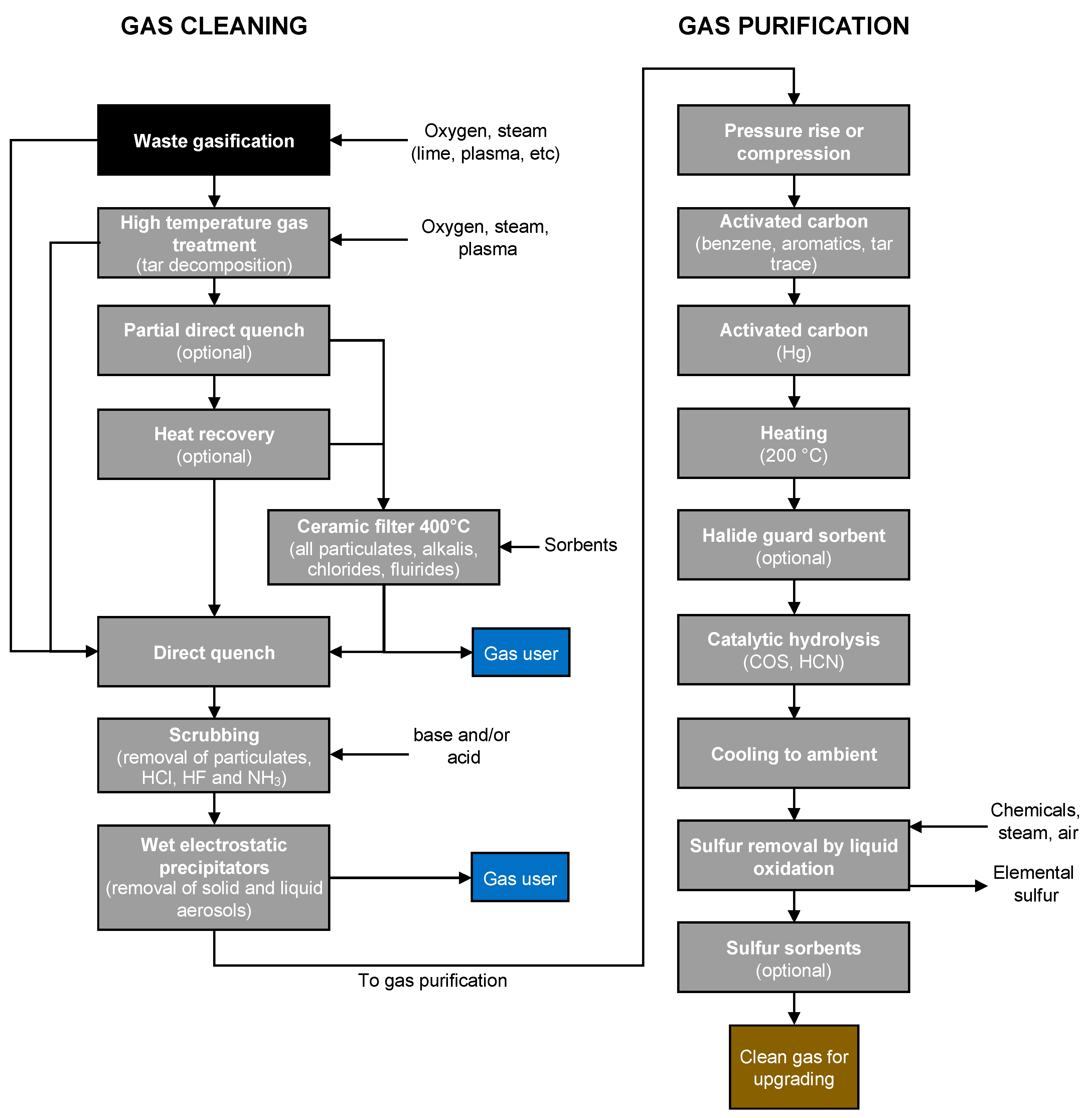
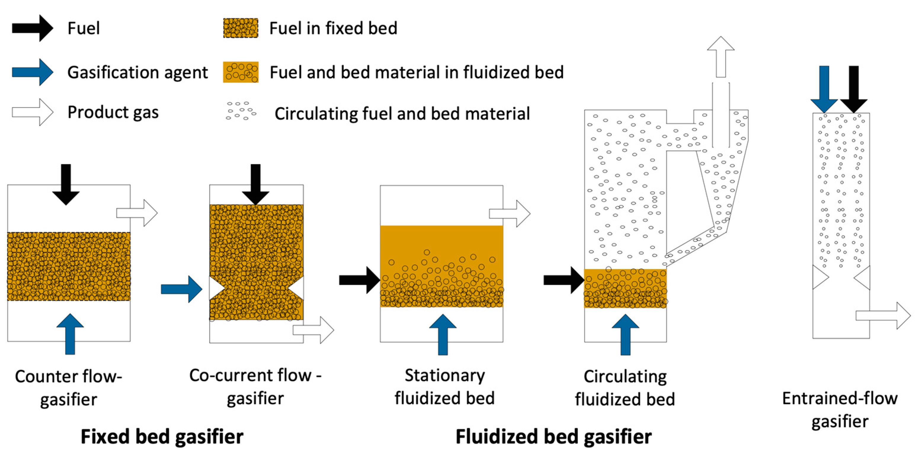
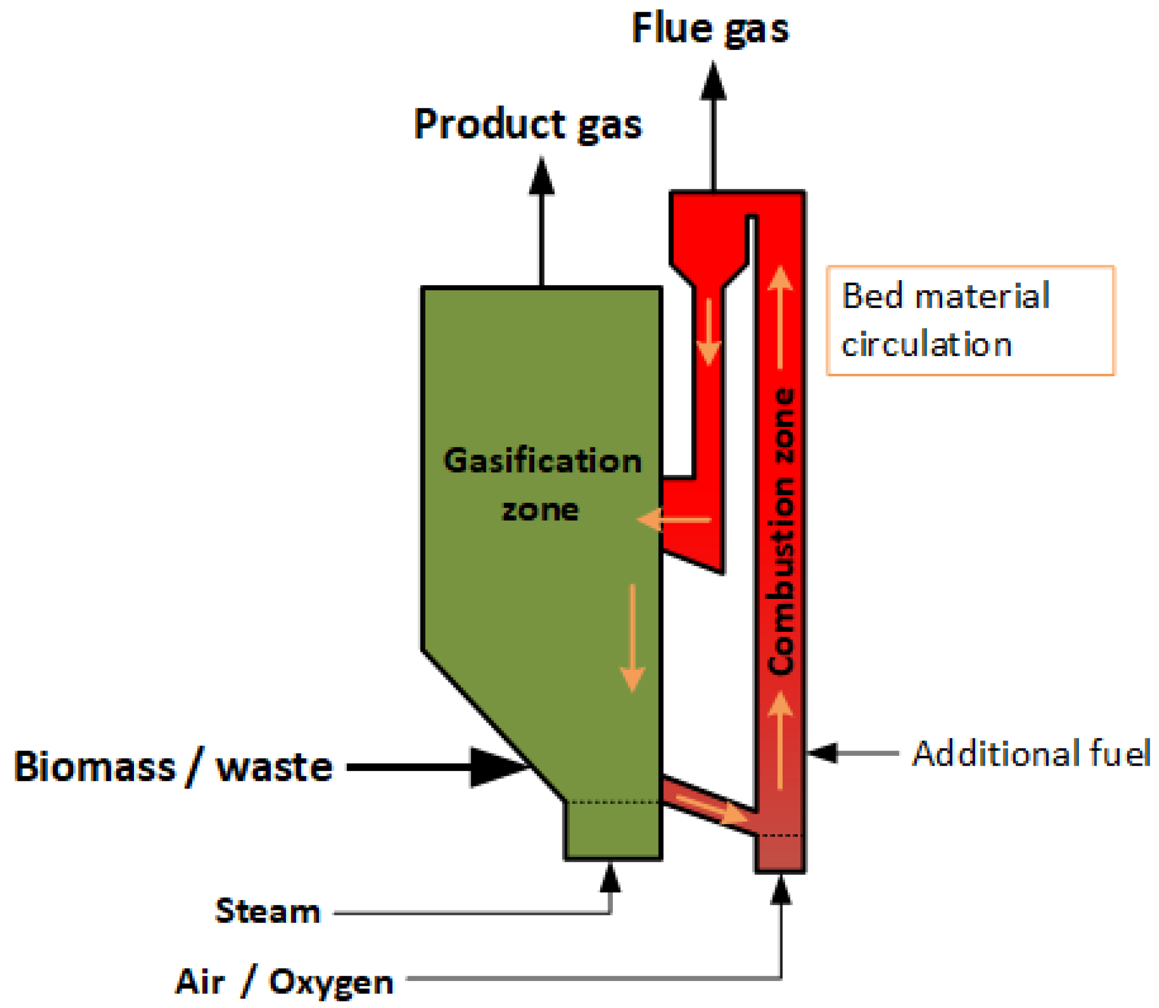
2.3. Gasification Processes

The advantage of gasification-based processes, compared to conventional combustion-based systems used today, is its ability to convert a solid fuel in such a way that specific chemical compounds can be isolated, e.g., CO and hydrogen, for use as a basis for the synthesis of chemical products or upgrading and separation to pure hydrogen. As waste contains numerous amounts of impurities, it is evident there is need for gas cleaning and upgrading, ranging from a few to several process steps, depending on the requirements of the application of the produced gas. Table 9 shows selected data for contaminants in raw product gas from waste gasification together with gas cleaning requirements related to different applications.
Figure 2 shows an example of a gas cleaning and purification train for upgrading to a synthesis gas. Note that the gas may be separated at different stages of cleaning for different application purposes and that some of the steps are optional depending on the needs for gas cleaning. Also, in the case of hydrogen production steps for upgrading by, e.g., WGS (Equation (5)), the separation of hydrogen should be added.
Prior to operation in the gasifier, the different types of waste including MSW must be prepared, sorted, and pretreated as they contain heterogeneous degradable and non-degradable mixtures in the form of food waste, yard waste, paper and cardboard, plastics, rubber, glass, electronic waste, metal, inert, and miscellaneous refuse [16,119]. Therefore, it is, in many cases, important to process the waste into structured forms of small pellets, fluffs with small particle sizes for increased bulk, and energy densities of the fuel, i.e., so-called RDF or SRF.
The next step is gasification, where the solid feedstock is converted to a combustible gas in a gasifier (various gasifier technologies are described in the subsequent section) followed by certain gas cleaning steps to convert tar and, if also needed, all other hydrocarbons, particulates, and alkali-, chloride-, fluoride-, and nitrogen-containing species. At this stage of cleaning, the produced gas may be used for heat and electricity production by, e.g., direct combustion in a boiler or in a gas engine.
In gas purification, the gas is further purified to meet the requirements of the final use of the gas by removal of trace levels of hydrocarbons, mainly aromatics, tars, and heavy metals, such as mercury, sulphur compounds, and HCN.
Figure 2 clearly shows that upgrading a raw gas, produced in waste gasification, to hydrogen is rather costly and adds significantly to the plant investment and operating costs.
Figure 2. Example of a waste gasification process for production of a clean synthesis gas. Adapted from [120]. Reproduced with permission from L. Waldheim, IEA Bioenergy, Paris, France 2019.
Hydrogen 05 00006 g002
Another option for the purification of the hydrogen is indirect processes, also called “chemical looping”. Here, the raw syngas is used to reduce a metal oxide to the metal and, in a subsequent step, the metal is then oxidized by steam, producing clean hydrogen. Several groups are working on this so-called steam–iron process, like TU Graz [121], who recently realized a 10 kW unit, or [122] demonstrated this for 250 kW or [123] 25 kW. Chemical looping for hydrogen production is based on very old methods of producing hydrogen, where one of the first patents were examined in 1911 [124]. The principle is that the fuel is gasified to a lean reducing gas, containing carbon monoxide and hydrogen. This gas reacts with iron oxides (hematite Fe2O3, magnetite Fe3O4, wuestite FeO) to produce a reduced form of iron oxide (wuestite FeO, iron Fe). The reduced iron oxide is re-oxidized with steam to form magnetite and hydrogen. In this way, very clean hydrogen can be produced from raw synthesis gas and dilution by inert gases, like nitrogen does not constitute a problem. An ongoing project in Austria converts biogas to hydrogen in the scale of 10 kW [125].

Gasifiers

There are several literature sources describing gasifier technologies and their features, and in the present review, we do not intend to be inclusive and only summarize based on information from selected sources [21,120,126,127].
Since most reactions occurring in the gasifier are endothermic, with the main exception being the oxidation of char (Equations (1) and (2)) or combustible gases (Equations (4), (8) and (9)) by oxygen, WGS (Equation (5)) and pyrolysis, which in certain temperature windows is exothermic, there is a need to supply or generate heat within the gasifier to balance the overall process. Gasifiers providing the needed heat by adding an oxidation agent, such as oxygen or air, to achieve partial oxidation of the fuel are called autothermal gasifiers or direct gasifiers. Thus, the heat produced is directly in the reactor. In case the heat is provided separately from a source outside the gasifier, it is referred to as allothermal gasifiers or indirect gasifiers. This means the heat consumed in a gasifier, where the fuel is gasified, is separated from the source of heat. Allothermal gasifiers can be divided into two main types: processes using a heat carrier, such as sand, circulating between a gasifier and combustion reactor; transfer of heat via an indirect heat exchanger where heat in, e.g., a hot flue gas, is transferred in the form of radiation and convection to the gasifier. There are certain disadvantages and advantages of the two types, as briefly outlined in Table 10.
In addition to pure autothermal and allothermal gasifiers, hybrid gasifiers also exist, as exemplified by indirect plasma gasifiers where heat from electricity is transferred via an injection of a plasma gas (most often air) as a heat carrier to the gasifier.
The type of gasifier used for the conversion greatly impacts the distribution and yield of the main reaction products of the raw product gas. Gasifiers are typically classified into three main groups viz. fixed-bed gasifiers, fluidized-bed gasifiers, and entrained-flow gasifiers, as shown in Figure 3. Table 11 shows selected characteristics for the main types of gasifiers.
Fixed-bed or moving-bed gasifiers including updraft and downdraft configurations have been used for waste gasification (Figure 3). The configuration relates to the input of feedstock and the gasifying agent. In the case of an updraft gasifier, the gasifying agent and the feedstock enter the bottom and the top of the reactor, respectively. Hot gases produced from oxidation in the bottom of the gasifier flow through the reduction zone (gasification, pyrolysis, and drying zone during its way out at the top of the reactor). This results in a subsequent decrease in the gas temperature, from high in the oxidation zone to low at the top and, as a consequence, a product gas with a high tar content (Table 11) as the tar-laden pyrolysis gas, produced in the pyrolysis zone, never passes through the high-temperature zone. The high tar content as well as the low product gas temperature are limiting factors, selecting this technology for the production of clean syngas or hydrogen as extensive tar decomposition mitigations are needed. The restricted capacity of <10 MW (Table 11) is mainly related to heat transfer and flow issues in the bed [120]. In downdraft gasifiers, the input of a gasifying agent is on the side or top of the gasifier, resulting in a different flow pattern compared to updraft gasifiers. This results in a lower tar content in the product gas as the gas passes through the high-temperature oxidation zone on its way out of the reactor. Although several studies report the use of this technology for various types of waste [129], a limiting factor is the potential capacity limited to <1 MW (Table 11). The limiting factor is the throat section of the gasifying agent inlet, where a scale up results in a bad mixing over the cross-section, causing channeling in the bed due to a less-uniform movement in the bed [120]. Waste used in moving-bed gasifiers needs be relatively uniform without too many fines and with sufficient mechanical strength to avoid the breakdown of fuel particles, caused by the weight of the bed. This is important as the bed porosity needs to be maintained to keep a realistic pressure drop.
Fluidized-bed gasifiers are mainly divided into bubbling (stationary) or circulating fluidized beds based on the principles of fluidization, where a fluidizing medium (generally a gas stream of air, steam of steam/oxygen mixtures in case of gasification) with a high enough gas velocity causes a bed material (inert or catalytically active) with a fuel to behave like a fluid. The fluidized bed provides high rates of heat and mass transfer and good mixing of the solids. This means that the temperature is relatively constant throughout the bed and that chemical reactions proceed at high rates. In the case of bubbling fluidized-bed gasifiers, the gas velocity is rather low and between 1 and 3 m/s to keep the bed material suspended by the gas. A freeboard (an enlargement in the reactor cross-section area) is used to separate particles, ejected by erupting bubbles, back to the bed. For a circulating fluidized bed, the gas velocities are much higher, 3–10 m/s, resulting in different hydrodynamics, where the solids are dispersed all over the tall riser. This allows for a long residence time for both the gas and the fine particles. The particles are, thereafter, separated from the gas in a cyclone and recycled back to the bottom of the reactor. Direct fluidized-bed gasifiers with large capacity are possible, as exemplified by the atmospheric biomass CFB gasifier at Vaskiluodon Voima in Vaasa, Finland, with a capacity of 140 MW thermal [130], but CFB boilers at even higher thermal capacities are also available. Dual-bed fluidized-bed gasifiers, as illustrated in Figure 4, are allothermal examples where two fluidized beds, any type, are combined, one acting as a gasifier and the second as a combustor [131]. They work in the same way as direct fluidized beds, but no oxidant is used in the gasifier; only steam and the heat required is supplied by hot bed material transferred from the combustor reactor. Fluidized-bed technologies have all been used for waste, but there are some specific requirements for the waste feedstock to be used. The feedstock particle size of any kind must have characteristics, such as particle size and density, to be able to sustain floating properties in the dense bed. For example, fines in the feedstock are entrained and leave the bed. In the case of waste, pre-treatment to RDF quality removing glass, metal, and other large inorganic objects is required.
Entrained-flow or suspension gasifiers are generally used for pressurized industrial large-scale coal (Table 11) gasification because of its higher availability, higher throughput, and better product gas quality [132]. In the case of coal, pulverized fuel (<1 mm) is injected together with the oxidant in a burner. The high temperatures used result in a very low content of tar and condensable gases, with methane composition close to the equilibrium. Entrained-flow gasifiers are generally not suitable for waste gasification, as either pumpable, atomizable liquid, or fine-powdered solid homogeneous feedstock is required. This restricts entrained-flow gasifiers to waste oils or potentially plastic wastes.
Other than the main gasifier types, there is also a number of other gasifier types, such as grate [133] and rotary kiln gasifiers [134], typically classified as moving-bed gasifiers, as illustrated in Figure 5. Grate and rotary kiln gasifiers are more suitable for non-uniform, compared to updraft and downdraft moving-bed gasifiers, as the movement of the bed is caused by mechanical work, improving the fuel mixing. Other examples are plasma gasifiers, which is not a basic type of gasifier but is a way to supply the heat at very high temperature to a gasifier or a downstream post-treatment reactor. The plasma is, in many cases, used in the updraft moving-bed gasifier type, where a carrier gas, e.g., air, steam, CO2, is ionized, generating a plasma in an electric arc at high temperature [133]
There are several aspects to consider when selecting a gasifier suitable for converting a solid feedstock to a gas suitable for further upgrading to chemicals or hydrogen. As waste is a fuel consisting of a variety of components, such as food waste, paper, plastic, rags, metal, glass, etc., a selected technology either needs to be able to handle the inhomogeneous waste feedstock as is, or different degrees of extensive pre-treatment of the waste are needed prior to feeding into the gasifier. There are pros and cons in both cases, as the former implies extensive gas cleaning and purification after the gasifier compared to the latter case, where some of the impurities may be mitigated in the pre-treatment process. In principle, costs related to investments in process or operation either end up before or after the gasifier. In any case, it is beneficial if both the feeding system and the gasifier can handle both course and fine materials and a varying degree of fuel quality.
Of special concern in the gasification of waste are the inorganics, particularly metallic compounds, such as heavy metals. They tend to evaporate at high temperatures and leave as aerosol particles [135]. Preferentially, they should be recovered in, e.g., the bottom ash, and this is one of the reasons many so-called waste gasifiers are operated at 400–600 °C, compared to biomass gasifiers operating at 800–900 °C [135]. However, a high gasification temperature benefits the thermal cracking of tars and hydrocarbons [44]. In any case, even when a high-grade pre-treatment of the waste is used, the non-combustible “ash” content is still higher compared to a typical biomass fuel, and, therefore, the capacity to extract ash and to control the ash inventory is important.

3. Opportunities and Risks

3.1. Potential of Hydrogen from Waste

Approximately 96% of hydrogen (H2) is currently produced by transforming fossil fuels (48% from natural gas, 30% from heavy oils and naphtha, and 18% from coal), which leads to CO2 emissions equivalent to 1.7% of the global energy-related CO2 emissions. Only 4% of the globally produced hydrogen stems from water electrolysis [136]. The H2 market is projected to grow by 50–82 metric tons by 2050 or approximately 5–10% per year [137].
The use of different feedstocks, primarily from biomass sources and wastes, would allow the full benefits of H2 to be realized as a clean, versatile, and efficient fuel, with new hydrogen-related policies emerging by 2030 [4,137]. The handling of waste as a likely source of H2 generation has attracted interest for its sustainable nature and for opening new opportunities for the comprehensive use of renewable energy sources [138]. Significant amounts of waste are produced in the agricultural, household, and industrial sectors that could be used in the production of H2 [139]. These wastes are categorized as organic wastes from food processing, crop residues, forest residues, industry, animal manure, agricultural wastes, household, and community wastes (municipal solid wastes, wastewater, etc.) [138]. Approximately 40–50 kg of hydrogen can be produced per ton of dry waste. In contrast, the amount of hydrogen can vary between 30 kg and 120 kg, depending on whether the waste mixtures contain water or moisture [140,141].
The potential of a wide variety of gaseous, liquid, and solid carbonaceous wastes has been investigated as a renewable source for hydrogen gas formation using various technologies (biological and thermochemical) [142]. Thermochemical processes such as gasification have been widely studied as promising processes for hydrogen production. Table 12 presents further results of potential hydrogen production from waste gasification using different reactors and gasifying agents.
According to a study by Khan et al. [149], steam gasification of palm kernel shells in fluidized-bed reactors produced 150 g H2/kg of H2. A similar H2 production potential (150.9 g H2/kg) was observed by Ganza and Lee [148] in microwave plasma gasification of mixed plastic waste, which is equivalent to 15 wt% of the initial sample. Lower and higher values have also been reported in other studies. In a study by Yao et al. [145], the H2 production potential through steam gasification in a dual-fluidized-bed reactor of wood chips was 39.7 g H2/kg. A higher potential of 199.6 g H2/kg was observed in the gasification of MSW in an allothermal fixed-bed downdraft gasifier [146].
Data on H2 production potential through gasification are divergent and show no patterns. This fact indicates the variability in data between different sources and even the influence of parameters in each process, so comparisons of data and information can lead to inconsistent conclusions. Nevertheless, it is possible to verify that the use of steam as a gasifying agent leads to a higher production of H2. The gasifying agents with the highest potential for H2 production have the following order: steam > mixture of steam and oxygen > oxygen.

3.2. Alternative Technologies

In addition to gasification, different production processes can be found, depending on the original source of hydrogen (e.g., wastewater, waste, and biomass). These production routes include thermochemical, electrolytic, and biological processes. However, some production methods are still under investigation [152,153]. Considering the technologies for converting waste and biomass into H2, the maturity level of the thermochemical pathways (gasification and pyrolysis) is aligned with TRL 7, whereas biological conversion is at TRL 4–5 and electrochemical conversion at TRL 2–4 [154]. Table 13 shows the main considerations for these different processes and Figure 6 represents a schematic of the different processes for producing H2 using renewable resources.
Thermochemical processes, such as gasification, pyrolysis, and steam reforming, are considered the most mature technologies and ready for application in hydrogen production [155]. Despite the low cost of the waste materials used, the high-temperature requirement is still the main limitation for these processes, particularly the steam reforming of methane (T = 1200 °C) [142]. According to Table 13, the CAPEX and hydrogen production costs of the biomass/waste gasification process are approximately 11–197.5 MEUR and 1.628–1.886 EUR/kg H2, respectively. According to Lepage et al. [154], both coal gasification and steam methane reforming of natural gas have a higher CAPEX, of 257.60 MEUR and 170.95–240.20 MEUR, respectively. The opposite effect is seen with the unit costs of hydrogen production are lower than those for biomass/waste gasification. These costs can be twice as low, ranging from 0.846 to 2.604 EUR/kg H2 for coal gasification and 0.71 EUR/kg H2 for steam methane reforming of natural gas [154]. In general, despite the lower CAPEX, H2 production via biomass/waste gasification is more expensive than using fossil resources.
For renewable raw material or waste, the costs of producing hydrogen by thermochemical processes are lower than biological processes according to Table 13. The cost of H2 production by gasification is approximately 22–31% lower than that of dark fermentation and approximately 28–37% lower than that of photo-fermentation.
Biological processes have a lower CAPEX but a high unit cost of H2 production (2364 EUR/kg H2 for dark fermentation and 2604 EUR/kg H2 for photo-fermentation). The possibility of large-scale production of H2 by biological processes is limited because of its low yield and stability [152], requiring pre-treatment processes to improve conversion performance [154]. However, biological processes are carried out by hydrogen-producing microorganisms (such as microalgae and cyanobacteria, which produce the enzymes needed to synthesize H2, including nitrogenases and hydrogenases). These microorganisms can be easily regenerated by replication, decreasing the frequency of renewal compared to chemical catalysts, which are easily deactivated during thermochemical conversions such as gasification [152,154]. In addition, biological conversion routes have the advantages of low temperature (30–60 °C), pressure (1 atm), and energy input (especially dark fermentation and enzyme-free photobiological processes) [154,155]. The main criteria for selecting waste for these biological processes are availability, cost, carbohydrate content, and biodegradability. Simple sugars, such as glucose, sucrose, and lactose, are readily biodegradable substrates and are preferred for hydrogen production [142]. For economical H2 production through biological processes, the substrate should be cheap and renewable. Substrates rich in starch and cellulose, such as plant stems or agricultural waste, or waste from the food industry are reported to support biological processes [158]. The two-stage thermophilic fermentation of three organic wastes (potato, kitchen waste, and okara, which is a bean curd manufacturing waste) was investigated by Chu et al. [159]. The H2 production rate was as follows: potato—2.1 LH2/Lfeedstock/d; garbage—1.7 LH2/Lfeedstock/d; okara—0.4 LH2/Lfeedstock/d in the continuous processes. The H2 yield was shown to be dependent not only on the proportion of carbohydrates but also on the hydrolysis pH of the organic waste, which was influenced by the nature of the organic materials in the waste [159]. Santos [160] studied the potential production of H2 through biological processes from the organic fraction of MSW. For a total of 25,758 t/year of of MSW, the author estimated the production of 411,233 m3/year of H2, corresponding to 32 vol% of the gas resulting from dark fermentation [160]. The dark fermentation of empty palm fruit clusters was studied by Gonzales et al. [161] and yields lie between 0.015 and 0.026 g H2/g biomass (169.53 and 286.98 mL H2/g biomass).
Biogas, produced from the anaerobic digestion of waste, is considered a good source of hydrogen and is an alternative to natural gas as a feedstock for methane steam reforming processes [162]. The biogas can be converted into 72% H2, resulting in a 10% reduction in costs [163]. Cudjoe et al. [164] studied the potential for H2 production from biogas produced from food waste in China’s Guangdong Province from 2004 to 2019. The authors found that 115.96 billion Nm3 of purified biogas produced during a defined period produced 26.60 billion kg of hydrogen [160]. The estimated potential for H2 production in south-western Nigeria from steam reforming of 1789.09 million Nm3/year purified biogas (methane) was 410.50 million kg H2/year, in Lagos alone, which would be 284.93 million kg H2/year [162].
Thermochemical processes generally have a significantly higher hydrogen production rate (up to 190 g H2/kg feed in the case of dry thermal gasification) than the biological process (up to 49 g H2/kg feed for the photo-biological process) [155]. Although dark fermentation has relatively low yields, experimental studies have favored it as a cheap, well-understood, and promising method that requires simple reactor designs, making it attractive among biological conversions [138,155]. Dark fermentation is the main mechanism for H2 production by biological processes [165], and integration with other systems, such as photo-fermentation and/or electrochemical systems as a secondary step, can pave the way for sustainable H2 production in large-scale systems, promoting a higher H2 yield and economic viability [166], being a potential competitor or expansion to the gasification process.
Electrochemical methods, such as electrocoagulation, indirect electrochemical oxidation, anodic oxidation, and electro-Fenton processes, have been effective for industrial wastewater treatment and H2 production [139]. Microbial electrolysis cells also have remarkable potential for wastewater treatment and the production of H2 and other value-added chemicals (e.g., methane (CH4), formic acid (HCOOH), and hydrogen peroxide), but this is still a laboratory-scale process with a low TRL (TRL 2–4). The specific energy consumption is considerably lower than the electricity consumed by the H2 production process through water electrolysis [139]. However, compared to thermochemical and biological technologies, these electrochemical conversion technologies require a huge energy input (approximately 45 kWh/kg H2 for typical electrolysis using water), have very low conversion rates, expensive catalysts, and other technological challenges; therefore, they are not competitive compared with biomass and waste gasification [155].

4. Regulations, Mandatory Recycling Quotas

The conversion of waste into hydrogen is considered very promising. However, as all the above technologies are still in research and development, there are many challenges, including technological, economic, and political aspects, that require further attention to be resolved [155]. As for policy issues, the question of mandatory recycling quotas for waste (especially plastics) and landfill reduction targets could contribute to the increased demand for technologies to convert this waste (e.g., gasification) into hydrogen and other energy carriers. However, according to an article published in the Yale School of the Environment (New Haven, Connecticut, USA), this would not be a wise solution, as it is false recycling that takes away from the political will of waste reduction. First, it is necessary to demand that the world’s largest plastic polluters reduce the amount of plastic they are pumping into the market [167].
The availability of biomass resources can also be a driving factor for the waste gasification market. It is well known that shrub areas are currently a global forest management problem, as shrubs are the main fuel for frequent forest fires in Europe [168]. Channeling this biomass, together with the use of municipal solid waste, could be a strategic measure for H2 production.
Policies should be strengthened to accelerate the deployment of clean and efficient energy technologies for hydrogen production and application [169]. The success of the market for clean hydrogen produced from wastes depends on the ability to define consistent and transparent norms, standards, and rules to facilitate its deployment. Standard settings can be an arena for geopolitical competition and international cooperation. Divergent standards can slow progress, lead to the fragmentation of the hydrogen market, and erect trade barriers. Standards should be designed to improve market quality, safety, and interoperability [170].
In 2017, only Japan had a national hydrogen strategy. More than 30 countries have now developed or are preparing hydrogen strategies, indicating a growing interest in the development of clean hydrogen value chains. The European Union (EU) published its hydrogen strategy in 2020, identifying hydrogen as a key priority for achieving the European Green Pact [170].
Some countries are implementing concrete policies, with particular emphasis on supporting commercial-scale projects for low-emission hydrogen production and infrastructure, such as the EU’s Important Projects of Common European Interest (IPCEI Hy2Tech and IPCEI Hy2Use), REPowerEU (hydrogen vouchers), the US Inflation Reduction Act, and auction systems for hydrogen procurement (German H2Global Initiative)) [5,171].
Hydrogen valleys contribute to REPowerEU’s goals by increasing the production and supply of hydrogen, thus meeting the growing demand from industry, transportation, and other sectors. Hydrogen valleys are regional ecosystems that link hydrogen production, transportation, and various end-uses, such as mobility or industrial feedstock. They enable the development of a sustainable hydrogen economy and help to create a virtuous circle between supply and demand, where large-scale production lowers costs and encourages greater demand in the same area. Co-location also reduces the immediate need for a long-haul transportation infrastructure. Even small-scale hydrogen valley projects can shed more light on the viability of a hydrogen economy that encompasses several industries simultaneously. The European Commission has allocated a Clean Hydrogen Partnership of an additional EUR 200 million through REPowerEU to double the number of hydrogen vouchers in Europe by 2025 [172,173].
Another instrument to support hydrogen technologies and drive the market is to provide financial assistance by reducing the high cost of market entry barriers. As the market matures, the nature of financial assistance provided may evolve from direct financial assistance to tax incentives and other types of subsidies [172].
In addition, phasing out fossil fuel subsidies, carbon pricing, and other market reforms can ensure appropriate price signals for hydrogen and foster the market [169].
Nevertheless, countries lack institutionalized mechanisms to monitor and identify the characteristics (origin and life-cycle emissions), production, and consumption of hydrogen. In addition, hydrogen is not accounted for in the official statistics of the total final energy consumption, and the economic value of the contribution of clean hydrogen to emission reductions is not recognized [170].
Therefore, there is not yet sufficient policy activity to create a demand for hydrogen. The lack of demand creation may hinder final investment decisions [5]. Without demand, investments are still too risky for large-scale production, which could reduce costs, but without economies of scale, the technology is still too expensive [170].

5. Conclusions

The gasification of waste is a very promising option to produce renewable hydrogen. There is significant literature available for experimental results at the lab and pilot scale. As feedstock, many different types of waste, like MSW, waste tires, or plastic waste, were investigated. Productivities of up to 300 g H2/kg feedstock have been reported, which indicates that technology may have a good basis for attractive economics. One main advantage of the gasification technology is its versatility and suitability for very different input materials, like different types and qualities of waste, and the syngas after treatment always has similar quality, independent of the quality of the feedstock.
Gas treatment is a very challenging step and can be a bottleneck for commercialization. A variety of different process arrangements (e.g., indirect processes such as chemical looping for gases with high inert content, and direct processes) can be applied, impacting the overall process performance and economics.
Overall, hydrogen from waste gasification has a high potential, as the productivity is high and waste is largely available all over the world. Competing technologies include pyrolysis, biological, or electrochemical processes, but most of them are at a lower TRL level than gasification. The main competing technology is combustion, where the energy production has a minor priority, but the main aim is to reduce the volume of the waste. Under the actual frame conditions, combustion is cheaper compared to gasification, as the energetic value is not rated, and the main aim is to remove the waste with as low costs as possible. By giving the energy in the waste a higher value, this situation could be changed, and gasification could become more competitive.
There are not only technical or economic aspects for waste gasification but also political ones. Waste conversion to energy is seen as negative in many countries, as recycling products is preferred. This is especially true for plastic waste. Conversion to hydrogen is a highly promosingoption for agricultural residues and waste streams with high contents of impurities, which are not usable for recycling. If the conversion of waste to hydrogen is accepted as chemical recycling, a much bigger market can be expected which in turn would greatly accelerate the technology development.

Author Contributions

Conceptualization, R.R.; methodology, R.R. and P.A.G.; writing—original draft preparation, Section 1 and Section 2, Y.K., K.E. and E.K.; Section 3 and Section 4, P.B., C.N. and S.M.S.; Abstract and Conclusion, R.R.; writing—review and editing, R.R. and P.A.G.; project administration, P.B.; funding acquisition, P.B. All authors have read and agreed to the published version of the manuscript.

Funding

This research was funded by the European Commission, grant number 952593. We acknowledge support by the KIT-Publication Fund of the Karlsruhe Institute of Technology.

Conflicts of Interest

The authors declare no conflicts of interest. The funders had no role in the design of the study; in the collection, analyses, or interpretation of data; in the writing of the manuscript; or in the decision to publish the results.

References

  1. Contreras, A.; Carpio, J.; Molero, M.; Veziroglu, T.N. Solar–Hydrogen: An Energy System for Sustainable Development in Spain. Int. J. Hydrogen Energy 1999, 24, 1041–1052. [Google Scholar] [CrossRef]
  2. Remón, J.; Arcelus-Arrillaga, P.; García, L.; Arauzo, J. Simultaneous Production of Gaseous and Liquid Biofuels from the Synergetic Co-Valorisation of Bio-Oil and Crude Glycerol in Supercritical Water. Appl. Energy 2018, 228, 2275–2287. [Google Scholar] [CrossRef]
  3. Kothari, R.; Buddhi, D.; Sawhney, R.L. Comparison of Environmental and Economic Aspects of Various Hydrogen Production Methods. Renew. Sustain. Energy Rev. 2008, 12, 553–563. [Google Scholar] [CrossRef]
  4. Lui, J.; Chen, W.-H.; Tsang, D.C.W.; You, S. A Critical Review on the Principles, Applications, and Challenges of Waste-to-Hydrogen Technologies. Renew. Sustain. Energy Rev. 2020, 134, 110365. [Google Scholar] [CrossRef]
  5. IEA. Global Hydrogen Review 2022; IEA: Paris, France, 2022. [Google Scholar]
  6. Kaza, S.; Yao, L.C.; Bhada-Tata, P.; Van Woerden, F. What a Waste 2.0: A Global Snapshot of Solid Waste Management to 2050; World Bank: Washington, DC, USA, 2018; ISBN 978-1-4648-1329-0. [Google Scholar]
  7. OECD. Global Plastics Outlook: Policy Scenarios to 2060; Organisation for Economic Co-operation and Development: Paris, France, 2022; ISBN 978-92-64-66764-8. [Google Scholar]
  8. Toledo, M.; Ripoll, N.; Céspedes, J.; Zbogar-Rasic, A.; Fedorova, N.; Jovicic, V.; Delgado, A. Syngas Production from Waste Tires Using a Hybrid Filtration Reactor under Different Gasifier Agents. Energy Convers. Manag. 2018, 172, 381–390. [Google Scholar] [CrossRef]
  9. Cheng, H.; Hu, Y. Municipal Solid Waste (MSW) as a Renewable Source of Energy: Current and Future Practices in China. Bioresour. Technol. 2010, 101, 3816–3824. [Google Scholar] [CrossRef] [PubMed]
  10. Chen, D.; Yin, L.; Wang, H.; He, P. Reprint of: Pyrolysis Technologies for Municipal Solid Waste: A Review. Waste Manag. 2015, 37, 116–136. [Google Scholar] [CrossRef] [PubMed]
  11. Couto, N.; Monteiro, E.; Silva, V.; Rouboa, A. Hydrogen-Rich Gas from Gasification of Portuguese Municipal Solid Wastes. Int. J. Hydrogen Energy 2016, 41, 10619–10630. [Google Scholar] [CrossRef]
  12. Jafri, Y.; Waldheim, L.; Lundgren, J. Emerging Gasification Technologies for Waste & Biomas; IEA Bioenergy: Paris, France, 2020. [Google Scholar]
  13. Belgiorno, V.; De Feo, G.; Della Rocca, C.; Napoli, R.M.A. Energy from Gasification of Solid Wastes. Waste Manag. 2003, 23, 1–15. [Google Scholar] [CrossRef]
  14. Sajid, M.; Raheem, A.; Ullah, N.; Asim, M.; Ur Rehman, M.S.; Ali, N. Gasification of Municipal Solid Waste: Progress, Challenges, and Prospects. Renew. Sustain. Energy Rev. 2022, 168, 112815. [Google Scholar] [CrossRef]
  15. Dimitriadis, A.; Bezergianni, S. Hydrothermal Liquefaction of Various Biomass and Waste Feedstocks for Biocrude Production: A State of the Art Review. Renew. Sustain. Energy Rev. 2017, 68, 113–125. [Google Scholar] [CrossRef]
  16. Nanda, S.; Berruti, F. Municipal Solid Waste Management and Landfilling Technologies: A Review. Environ. Chem. Lett. 2021, 19, 1433–1456. [Google Scholar] [CrossRef]
  17. Lombardi, L.; Carnevale, E.; Corti, A. Review of Technologies and Performances of Thermal Treatment Systems for Energy Recovery from Waste. Waste Manag. 2015, 37, 26–44. [Google Scholar] [CrossRef] [PubMed]
  18. Arena, U. Process and Technological Aspects of Municipal Solid Waste Gasification. A Review. Waste Manag. 2012, 32, 625–639. [Google Scholar] [CrossRef] [PubMed]
  19. El-Rub, Z.A.; Bramer, E.A.; Brem, G. Review of Catalysts for Tar Elimination in Biomass Gasification Processes. Ind. Eng. Chem. Res. 2004, 43, 6911–6919. [Google Scholar] [CrossRef]
  20. Milne, T.A.; Elam, C.C.; Evans, R.J. Hydrogen from Biomass: State of the Art and Research Challenges. In International Energy Agency, Agreement on the Production and Utilization of Hydrogen; IEA/H2-TR-02/001; United States Department of Energy: Washington, DC, USA, 2002. [Google Scholar] [CrossRef]
  21. Nguyen, V.G.; Nguyen-Thi, T.X.; Phong Nguyen, P.Q.; Tran, V.D.; Ağbulut, Ü.; Nguyen, L.H.; Balasubramanian, D.; Tarelko, W.; Bandh, S.A.; Khoa Pham, N.D.K. Recent Advances in Hydrogen Production from Biomass Waste with a Focus on Pyrolysis and Gasification. Int. J. Hydrogen Energy 2024, 54, 127–160. [Google Scholar] [CrossRef]
  22. Munir, M.T.; Mardon, I.; Al-Zuhair, S.; Shawabkeh, A.; Saqib, N.U. Plasma Gasification of Municipal Solid Waste for Waste-to-Value Processing. Renew. Sustain. Energy Rev. 2019, 116, 109461. [Google Scholar] [CrossRef]
  23. Klinghoffer, N.; Castaldi, M. Gasification and Pyrolysis of Municipal Solid Waste (MSW). In Waste to Energy Conversion Technology; Woodhead Publishing: Cambridge, UK, 2013; pp. 146–176. ISBN 978-0-85709-011-9. [Google Scholar]
  24. Butterman, H.C.; Castaldi, M.J. CO2 as a Carbon Neutral Fuel Source via Enhanced Biomass Gasification. Environ. Sci. Technol. 2009, 43, 9030–9037. [Google Scholar] [CrossRef]
  25. Sansaniwal, S.K.; Pal, K.; Rosen, M.A.; Tyagi, S.K. Recent Advances in the Development of Biomass Gasification Technology: A Comprehensive Review. Renew. Sustain. Energy Rev. 2017, 72, 363–384. [Google Scholar] [CrossRef]
  26. Parthasarathy, P.; Narayanan, K.S. Hydrogen Production from Steam Gasification of Biomass: Influence of Process Parameters on Hydrogen Yield—A Review. Renew. Energy 2014, 66, 570–579. [Google Scholar] [CrossRef]
  27. Park, S.-W.; Lee, J.-S.; Yang, W.S.; Alam, T.; Seo, Y.-C. A Comparative Study of the Gasification of Solid Refuse Fuel in Downdraft Fixed Bed and Bubbling Fluidized Bed Reactors. Waste Biomass Valorization 2020, 11, 2345–2356. [Google Scholar] [CrossRef]
  28. Velis, C.A.; Longhurst, P.J.; Drew, G.H.; Smith, R.; Pollard, S.J.T. Production and Quality Assurance of Solid Recovered Fuels Using Mechanical—Biological Treatment (MBT) of Waste: A Comprehensive Assessment. Crit. Rev. Environ. Sci. Technol. 2010, 40, 979–1105. [Google Scholar] [CrossRef]
  29. Jamro, I.; Chen, G.; Baloch, H.; Wenga, T.; Ma, W. Optimization of Municipal Solid Waste Air Gasification for Higher H2 Production along with the Validation via Kinetics and Statistical Approaches. Fuel 2022, 322, 124137. [Google Scholar] [CrossRef]
  30. Zheng, X.; Ying, Z.; Wang, B.; Chen, C. Hydrogen and Syngas Production from Municipal Solid Waste (MSW) Gasification via Reusing CO2. Appl. Therm. Eng. 2018, 144, 242–247. [Google Scholar] [CrossRef]
  31. He, M.; Hu, Z.; Xiao, B.; Li, J.; Guo, X.; Luo, S.; Yang, F.; Feng, Y.; Yang, G.; Liu, S. Hydrogen-Rich Gas from Catalytic Steam Gasification of Municipal Solid Waste (MSW): Influence of Catalyst and Temperature on Yield and Product Composition. Int. J. Hydrogen Energy 2009, 34, 195–203. [Google Scholar] [CrossRef]
  32. Chen, G.; Jamro, I.A.; Samo, S.R.; Wenga, T.; Baloch, H.A.; Yan, B.; Ma, W. Hydrogen-Rich Syngas Production from Municipal Solid Waste Gasification through the Application of Central Composite Design: An Optimization Study. Int. J. Hydrogen Energy 2020, 45, 33260–33273. [Google Scholar] [CrossRef]
  33. Zhao, J.; Xie, D.; Wang, S.; Zhang, R.; Wu, Z.; Meng, H.; Chen, L.; Wang, T.; Guo, Y. Hydrogen-Rich Syngas Produced from Co-Gasification of Municipal Solid Waste and Wheat Straw in an Oxygen-Enriched Air Fluidized Bed. Int. J. Hydrogen Energy 2021, 46, 18051–18063. [Google Scholar] [CrossRef]
  34. Zhou, C.; Stuermer, T.; Gunarathne, R.; Yang, W.; Blasiak, W. Effect of Calcium Oxide on High-Temperature Steam Gasification of Municipal Solid Waste. Fuel 2014, 122, 36–46. [Google Scholar] [CrossRef]
  35. Wang, J.; Cheng, G.; You, Y.; Xiao, B.; Liu, S.; He, P.; Guo, D.; Guo, X.; Zhang, G. Hydrogen-Rich Gas Production by Steam Gasification of Municipal Solid Waste (MSW) Using NiO Supported on Modified Dolomite. Int. J. Hydrogen Energy 2012, 37, 6503–6510. [Google Scholar] [CrossRef]
  36. Campoy, M.; Gomez-Barea, A.; Ollero, P.; Nilsson, S. Gasification of Wastes in a Pilot Fluidized Bed Gasifier. Fuel Process. Technol. 2014, 121, 63–69. [Google Scholar] [CrossRef]
  37. Domínguez, A.; Menéndez, J.A.; Pis, J.J. Hydrogen Rich Fuel Gas Production from the Pyrolysis of Wet Sewage Sludge at High Temperature. J. Anal. Appl. Pyrolysis 2006, 77, 127–132. [Google Scholar] [CrossRef]
  38. Hu, M.; Guo, D.; Ma, C.; Hu, Z.; Zhang, B.; Xiao, B.; Luo, S.; Wang, J. Hydrogen-Rich Gas Production by the Gasification of Wet MSW (Municipal Solid Waste) Coupled with Carbon Dioxide Capture. Energy 2015, 90, 857–863. [Google Scholar] [CrossRef]
  39. Kumar, U.; Paul, M.C. CFD Modelling of Biomass Gasification with a Volatile Break-up Approach. Chem. Eng. Sci. 2019, 195, 413–422. [Google Scholar] [CrossRef]
  40. Gohlke, O. Efficiency of Energy Recovery from Municipal Solid Waste and the Resultant Effect on the Greenhouse Gas Balance. Waste Manag. Res. J. Int. Solid Wastes Public Clean. Assoc. ISWA 2009, 27, 894–906. [Google Scholar] [CrossRef]
  41. Scala, F.; Solimene, R.; Montagnaro, F. 7—Conversion of Solid Fuels and Sorbents in Fluidized Bed Combustion and Gasification. In Fluidized Bed Technologies for Near-Zero Emission Combustion and Gasification; Scala, F., Ed.; Woodhead Publishing Series in Energy; Woodhead Publishing: Cambridge, UK, 2013; pp. 319–387. ISBN 978-0-85709-541-1. [Google Scholar]
  42. Cao, L.; Yu, I.K.M.; Xiong, X.; Tsang, D.C.W.; Zhang, S.; Clark, J.H.; Hu, C.; Ng, Y.H.; Shang, J.; Ok, Y.S. Biorenewable Hydrogen Production through Biomass Gasification: A Review and Future Prospects. Environ. Res. 2020, 186, 109547. [Google Scholar] [CrossRef] [PubMed]
  43. Lv, P.; Wu, C.; Ma, L.; Yuan, Z. A Study on the Economic Efficiency of Hydrogen Production from Biomass Residues in China. Renew. Energy 2008, 33, 1874–1879. [Google Scholar] [CrossRef]
  44. Luo, S.; Xiao, B.; Guo, X.; Hu, Z.; Liu, S.; He, M. Hydrogen-Rich Gas from Catalytic Steam Gasification of Biomass in a Fixed Bed Reactor: Influence of Particle Size on Gasification Performance. Int. J. Hydrogen Energy 2009, 34, 1260–1264. [Google Scholar] [CrossRef]
  45. Bhoi, P.R.; Huhnke, R.L.; Kumar, A.; Indrawan, N.; Thapa, S. Co-Gasification of Municipal Solid Waste and Biomass in a Commercial Scale Downdraft Gasifier. Energy 2018, 163, 513–518. [Google Scholar] [CrossRef]
  46. Li, J.; Liao, S.; Dan, W.; Jia, K.; Zhou, X. Experimental Study on Catalytic Steam Gasification of Municipal Solid Waste for Bioenergy Production in a Combined Fixed Bed Reactor. Biomass Bioenergy 2012, 46, 174–180. [Google Scholar] [CrossRef]
  47. Gao, W.; Farahani, M.R.; Rezaei, M.; Hosamani, S.M.; Jamil, M.K.; Imran, M.; Baig, A.Q. Experimental Study of Steam-Gasification of Municipal Solid Wastes (MSW) Using Ni-Cu/Γ-Al 2O3 Nano Catalysts. Energy Sources Part Recovery Util. Environ. Eff. 2017, 39, 693–697. [Google Scholar] [CrossRef]
  48. Couto, N.; Silva, V.; Monteiro, E.; Rouboa, A. Exergy Analysis of Portuguese Municipal Solid Waste Treatment via Steam Gasification. Energy Convers. Manag. 2017, 134, 235–246. [Google Scholar] [CrossRef]
  49. Mallick, D.; Mahanta, P.; Moholkar, V.S. Co-Gasification of Coal and Biomass Blends: Chemistry and Engineering. Fuel 2017, 204, 106–128. [Google Scholar] [CrossRef]
  50. Luo, S.; Zhou, Y.; Yi, C. Syngas Production by Catalytic Steam Gasification of Municipal Solid Waste in Fixed-Bed Reactor. Energy 2012, 44, 391–395. [Google Scholar] [CrossRef]
  51. Machin, E.B.; Pedroso, D.T.; de Carvalho, J.A. Energetic Valorization of Waste Tires. Renew. Sustain. Energy Rev. 2017, 68, 306–315. [Google Scholar] [CrossRef]
  52. Leung, D.Y.C.; Wang, C.L. Fluidized-Bed Gasification of Waste Tire Powders. Fuel Process. Technol. 2003, 84, 175–196. [Google Scholar] [CrossRef]
  53. Mastral, A.M.; Murillo, R.; Garcia, T.; Navarro, M.; Callén, M.; Lopez, J. Study of the Viability of the Process for Hydrogen Recovery from Old Tyre Oils. Fuel Process. Technol. 2002, 75, 185–199. [Google Scholar] [CrossRef]
  54. Home—ETRMA. Available online: https://www.etrma.org/ (accessed on 25 November 2023).
  55. Torretta, V.; Rada, E.C.; Ragazzi, M.; Trulli, E.; Istrate, I.A.; Cioca, L.I. Treatment and Disposal of Tyres: Two EU Approaches. A Review. Waste Manag. 2015, 45, 152–160. [Google Scholar] [CrossRef]
  56. Yin, C.-Y. Prediction of Higher Heating Values of Biomass from Proximate and Ultimate Analyses. Fuel 2011, 90, 1128–1132. [Google Scholar] [CrossRef]
  57. Tan, P.; Zhang, C.; Xia, J.; Fang, Q.-Y.; Chen, G. Estimation of Higher Heating Value of Coal Based on Proximate Analysis Using Support Vector Regression. Fuel Process. Technol. 2015, 138, 298–304. [Google Scholar] [CrossRef]
  58. Li, W.; Huang, C.; Li, D.; Huo, P.; Wang, M.; Han, L.; Chen, G.; Li, H.; Li, X.; Wang, Y.; et al. Derived Oil Production by Catalytic Pyrolysis of Scrap Tires. Chin. J. Catal. 2016, 37, 526–532. [Google Scholar] [CrossRef]
  59. Ayanoglu, A.; Yumrutas, R. Rotary Kiln and Batch Pyrolysis of Waste Tire to Produce Gasoline and Diesel like Fuels. Energy Convers. Manag. 2016, 111, 261–270. [Google Scholar] [CrossRef]
  60. Portofino, S.; Donatelli, A.; Iovane, P.; Innella, C.; Civita, R.; Martino, M.; Matera, D.A.; Russo, A.; Cornacchia, G.; Galvagno, S. Steam Gasification of Waste Tyre: Influence of Process Temperature on Yield and Product Composition. Waste Manag. 2013, 33, 672–678. [Google Scholar] [CrossRef] [PubMed]
  61. Nanda, S.; Sivamohan Reddy, N.; Hunter, H.; Vo, D.-V.; Kozinski, J.; Gökalp, I. Catalytic Subcritical and Supercritical Water Gasification as a Resource Recovery Approach from Waste Tires for Hydrogen-Rich Syngas Production. J. Supercrit. Fluids 2019, 154, 104627. [Google Scholar] [CrossRef]
  62. Karatas, H.; Olgun, H.; Engin, B.; Akgun, F. Experimental Results of Gasification of Waste Tire with Air in a Bubbling Fluidized Bed Gasifier. Fuel 2013, 105, 566–571. [Google Scholar] [CrossRef]
  63. Portofino, S.; Casu, S.; Iovane, P.; Russo, A.; Martino, M.; Donatelli, A.; Galvagno, S. Optimizing H2 Production from Waste Tires via Combined Steam Gasification and Catalytic Reforming. Energy Fuels 2011, 25, 2232–2241. [Google Scholar] [CrossRef]
  64. Zhang, Y.; Chunfei, W.; Nahil, M.; Williams, P. Pyrolysis-Catalytic Steam Reforming/Gasification of Waste Tires for Production of Carbon Nanotubes and Hydrogen. Energy Fuels 2015, 29, 150415125425001. [Google Scholar] [CrossRef]
  65. Zhang, X.; Wang, T.; Ma, L.; Chang, J. Vacuum Pyrolysis of Waste Tires with Basic Additives. Waste Manag. 2008, 28, 2301–2310. [Google Scholar] [CrossRef]
  66. Han, W.; Han, D.; Chen, H. Pyrolysis of Waste Tires: A Review. Polymers 2023, 15, 1604. [Google Scholar] [CrossRef]
  67. Singh, R.K.; Ruj, B.; Jana, A.; Mondal, S.; Jana, B.; Sadhukhan, A.K.; Gupta, P. Pyrolysis of Three Different Categories of Automotive Tyre Wastes: Product Yield Analysis and Characterization. J. Anal. Appl. Pyrolysis 2018, 135, 379–389. [Google Scholar] [CrossRef]
  68. Akkouche, N.; Balistrou, M.; Loubar, K.; Awad, S.; Tazerout, M. Heating Rate Effects on Pyrolytic Vapors from Scrap Truck Tires. J. Anal. Appl. Pyrolysis 2016, 123, 419–429. [Google Scholar] [CrossRef]
  69. Sathiskumar, C.; Karthikeyan, S. Recycling of Waste Tires and Its Energy Storage Application of By-Products—A Review. Sustain. Mater. Technol. 2019, 22, e00125. [Google Scholar] [CrossRef]
  70. Pattabhi Raman, K.; Walawender, W.P.; Fan, L.T. Gasification of Waste Tires in a Fluid Bed Reactor. Conserv. Recycl. 1981, 4, 79–88. [Google Scholar] [CrossRef]
  71. Elbaba, I.; Chunfei, W.; Williams, P. Hydrogen Production from the Pyrolysis–Gasification of Waste Tyres with a Nickel/Cerium Catalyst. Energy Fuels 2011, 36, 6628–6637. [Google Scholar] [CrossRef]
  72. Elbaba, I.; Williams, P. High Yield Hydrogen from the Pyrolysis–Catalytic Gasification of Waste Tyres with a Nickel/Dolomite Catalyst. Fuel 2013, 106, 528–536. [Google Scholar] [CrossRef]
  73. Elbaba, I.; Williams, P. Two Stage Pyrolysis-Catalytic Gasification of Waste Tyres: Influence of Process Parameters. Appl. Catal. B Environ. 2012, 125, 136–143. [Google Scholar] [CrossRef]
  74. Donatelli, A.; Iovane, P.; Molino, A. High Energy Syngas Production by Waste Tyres Steam Gasification in a Rotary Kiln Pilot Plant. Experimental and Numerical Investigations. Fuel 2010, 89, 2721–2728. [Google Scholar] [CrossRef]
  75. Karatas, H.; Olgun, H.; Akgun, F. Experimental Results of Gasification of Waste Tire with air&CO2, Air&steam and Steam in a Bubbling Fluidized Bed Gasifier. Fuel Process. Technol. 2012, 102, 166–174. [Google Scholar] [CrossRef]
  76. Xiao, G.; Ni, M.-J.; Chi, Y.; Cen, K.-F. Low-Temperature Gasification of Waste Tire in a Fluidized Bed. Energy Convers. Manag. 2008, 49, 2078–2082. [Google Scholar] [CrossRef]
  77. Al-Qadri, A.A.; Ahmed, U.; Abdul Jameel, A.G.; Zahid, U.; Ahmad, N.; Shahbaz, M.; Nemitallah, M.A. Technoeconomic Feasibility of Hydrogen Production from Waste Tires with the Control of CO2 Emissions. ACS Omega 2022, 7, 48075–48086. [Google Scholar] [CrossRef]
  78. Fox, J.A.; Stacey, N.T. Process Targeting: An Energy Based Comparison of Waste Plastic Processing Technologies. Energy 2019, 170, 273–283. [Google Scholar] [CrossRef]
  79. Jambeck, J.R.; Geyer, R.; Wilcox, C.; Siegler, T.R.; Perryman, M.; Andrady, A.; Narayan, R.; Law, K.L. Plastic Waste Inputs from Land into the Ocean. Science 2015, 347, 768–771. [Google Scholar] [CrossRef]
  80. Yong, C.Q.Y.; Valiyaveettil, S.; Tang, B.L. Toxicity of Microplastics and Nanoplastics in Mammalian Systems. Int. J. Environ. Res. Public Health 2020, 17, 1509. [Google Scholar] [CrossRef]
  81. Yang, R.-X.; Chuang, K.-H.; Wey, M.-Y. Effects of Nickel Species on Ni/Al2O3 Catalysts in CNTs and Hydrogen Production by Waste Plastics Gasification: Bench-Scale and Pilot-Scale Tests. Energy Fuels 2015, 29, 8178–8187. [Google Scholar] [CrossRef]
  82. Wilk, V.; Hofbauer, H. Conversion of Mixed Plastic Wastes in a Dual Fluidized Bed Steam Gasifier. Fuel 2013, 107, 787–799. [Google Scholar] [CrossRef]
  83. Jeong, Y.-S.; Park, K.-B.; Kim, J.-S. Hydrogen Production from Steam Gasification of Polyethylene Using a Two-Stage Gasifier and Active Carbon. Appl. Energy 2020, 262, 114495. [Google Scholar] [CrossRef]
  84. Burra, K.G.; Gupta, A.K. Synergistic Effects in Steam Gasification of Combined Biomass and Plastic Waste Mixtures. Appl. Energy 2018, 211, 230–236. [Google Scholar] [CrossRef]
  85. Choi, M.-J.; Jeong, Y.-S.; Kim, J.-S. Air Gasification of Polyethylene Terephthalate Using a Two-Stage Gasifier with Active Carbon for the Production of H2 and CO. Energy 2021, 223, 120122. [Google Scholar] [CrossRef]
  86. Sancho, J.A.; Aznar, M.P.; Toledo, J.M. Catalytic Air Gasification of Plastic Waste (Polypropylene) in Fluidized Bed. Part I: Use of in-Gasifier Bed Additives. Ind. Eng. Chem. Res. 2008, 47, 1005–1010. [Google Scholar] [CrossRef]
  87. Cho, M.-H.; Choi, Y.-K.; Kim, J.-S. Air Gasification of PVC (Polyvinyl Chloride)-Containing Plastic Waste in a Two-Stage Gasifier Using Ca-Based Additives and Ni-Loaded Activated Carbon for the Production of Clean and Hydrogen-Rich Producer Gas. Energy 2015, 87, 586–593. [Google Scholar] [CrossRef]
  88. Chai, Y.; Gao, N.; Wang, M.; Wu, C. H2 Production from Co-Pyrolysis/Gasification of Waste Plastics and Biomass under Novel Catalyst Ni-CaO-C. Chem. Eng. J. 2020, 382, 122947. [Google Scholar] [CrossRef]
  89. Farooq, A.; Song, H.; Park, Y.K.; Rhee, G.H. Effects of Different Al2O3 Support on HDPE Gasification for Enhanced Hydrogen Generation Using Ni-Based Catalysts. Int. J. Hydrogen Energy 2021, 46, 18085–18092. [Google Scholar] [CrossRef]
  90. Chunfei, W.; Williams, P. Pyrolysis–Gasification of Plastics, Mixed Plastics and Real-World Plastic Waste with and Without Ni–Mg–Al Catalyst. Energy Fuels 2010, 89, 3022–3032. [Google Scholar] [CrossRef]
  91. Arena, U.; Di Gregorio, F. Energy Generation by Air Gasification of Two Industrial Plastic Wastes in a Pilot Scale Fluidized Bed Reactor. Energy 2014, 68, 735–743. [Google Scholar] [CrossRef]
  92. Mastellone, M.L.; Zaccariello, L.; Arena, U. Co-Gasification of Coal, Plastic Waste and Wood in a Bubbling Fluidized Bed Reactor. Fuel 2010, 89, 2991–3000. [Google Scholar] [CrossRef]
  93. Straka, P.; Bičáková, O. Hydrogen-Rich Gas as a Product of Two-Stage Co-Gasification of Lignite/Waste Plastics Mixtures. Int. J. Hydrogen Energy 2014, 39, 10987–10995. [Google Scholar] [CrossRef]
  94. Han, S.W.; Tokmurzin, D.; Lee, J.J.; Park, S.J.; Ra, H.W.; Yoon, S.J.; Mun, T.-Y.; Yoon, S.M.; Moon, J.H.; Lee, J.G.; et al. Gasification Characteristics of Waste Plastics (SRF) in a Bubbling Fluidized Bed: Use of Activated Carbon and Olivine for Tar Removal and the Effect of Steam/Carbon Ratio. Fuel 2022, 314, 123102. [Google Scholar] [CrossRef]
  95. Han, S.W.; Lee, J.J.; Tokmurzin, D.; Lee, S.H.; Nam, J.Y.; Park, S.J.; Ra, H.W.; Mun, T.-Y.; Yoon, S.J.; Yoon, S.M. Gasification Characteristics of Waste Plastics (SRF) in a Bubbling Fluidized Bed: Effects of Temperature and Equivalence Ratio. Energy 2022, 238, 121944. [Google Scholar] [CrossRef]
  96. Dou, B.; Wang, K.; Jiang, B.; Song, Y.; Zhang, C.; Chen, H.; Xu, Y. Fluidized-Bed Gasification Combined Continuous Sorption-Enhanced Steam Reforming System to Continuous Hydrogen Production from Waste Plastic. Int. J. Hydrogen Energy 2016, 41, 3803–3810. [Google Scholar] [CrossRef]
  97. Lazzarotto, I.P.; Ferreira, S.D.; Junges, J.; Bassanesi, G.R.; Manera, C.; Perondi, D.; Godinho, M. The Role of CaO in the Steam Gasification of Plastic Wastes Recovered from the Municipal Solid Waste in a Fluidized Bed Reactor. Process Saf. Environ. Prot. 2020, 140, 60–67. [Google Scholar] [CrossRef]
  98. Cho, M.-H.; Mun, T.-Y.; Choi, Y.-K.; Kim, J.-S. Two-Stage Air Gasification of Mixed Plastic Waste: Olivine as the Bed Material and Effects of Various Additives and a Nickel-Plated Distributor on the Tar Removal. Energy 2014, 70, 128–134. [Google Scholar] [CrossRef]
  99. Plastic Waste and Recycling in the EU: Facts and Figures|News|European Parliament. Available online: https://www.europarl.europa.eu/news/en/headlines/society/20181212STO21610/plastic-waste-and-recycling-in-the-eu-facts-and-figures (accessed on 25 November 2023).
  100. Anuar Sharuddin, S.D.; Abnisa, F.; Wan Daud, W.M.A.; Aroua, M.K. A Review on Pyrolysis of Plastic Wastes. Energy Convers. Manag. 2016, 115, 308–326. [Google Scholar] [CrossRef]
  101. Qureshi, M.S.; Oasmaa, A.; Pihkola, H.; Deviatkin, I.; Tenhunen, A.; Mannila, J.; Minkkinen, H.; Pohjakallio, M.; Laine-Ylijoki, J. Pyrolysis of Plastic Waste: Opportunities and Challenges. J. Anal. Appl. Pyrolysis 2020, 152, 104804. [Google Scholar] [CrossRef]
  102. Kunwar, B.; Cheng, H.N.; Chandrashekaran, S.R.; Sharma, B.K. Plastics to Fuel: A Review. Renew. Sustain. Energy Rev. 2016, 54, 421–428. [Google Scholar] [CrossRef]
  103. Zhang, Y.; Duan, D.; Lei, H.; Villota, E.; Ruan, R. Jet Fuel Production from Waste Plastics via Catalytic Pyrolysis with Activated Carbons. Appl. Energy 2019, 251, 113337. [Google Scholar] [CrossRef]
  104. Aishwarya, K.N.; Nangarthody, S. Microwave Assisted Pyrolysis of Plastic Waste. Procedia Technol. 2016, 25, 990–997. [Google Scholar] [CrossRef]
  105. Zhang, X.; Lei, H.; Yadavalli, G.; Zhu, L.; Wei, Y.; Liu, Y. Gasoline-Range Hydrocarbons Produced from Microwave-Induced Pyrolysis of Low-Density Polyethylene over ZSM-5. Fuel 2015, 144, 33–42. [Google Scholar] [CrossRef]
  106. Lopez, G.; Artetxe, M.; Amutio, M.; Alvarez, J.; Bilbao, J.; Olazar, M. Recent Advances in the Gasification of Waste Plastics. A Critical Overview. Renew. Sustain. Energy Rev. 2018, 82, 576–596. [Google Scholar] [CrossRef]
  107. Midilli, A.; Kucuk, H.; Haciosmanoglu, M.; Akbulut, U.; Dincer, I. A Review on Converting Plastic Wastes into Clean Hydrogen via Gasification for Better Sustainability. Int. J. Energy Res. 2022, 46, 4001–4032. [Google Scholar] [CrossRef]
  108. He, M.; Xiao, B.; Hu, Z.; Liu, S.; Guo, X.; Luo, S. Syngas Production from Catalytic Gasification of Waste Polyethylene: Influence of Temperature on Gas Yield and Composition. Int. J. Hydrogen Energy 2009, 34, 1342–1348. [Google Scholar] [CrossRef]
  109. Huang, J.; Veksha, A.; Jun, T.; Lisak, G. Upgrading Waste Plastic Derived Pyrolysis Gas via Chemical Looping Cracking–Gasification Using Ni–Fe–Al Redox Catalysts. Chem. Eng. J. 2022, 438, 135580. [Google Scholar] [CrossRef]
  110. Zhang, S.; Zhu, S.; Zhang, H.; Liu, X.; Xiong, Y. High Quality H2-Rich Syngas Production from Pyrolysis-Gasification of Biomass and Plastic Wastes by Ni–Fe@Nanofibers/Porous Carbon Catalyst. Int. J. Hydrogen Energy 2019, 44, 26193–26203. [Google Scholar] [CrossRef]
  111. Martínez-Lera, S.; Torrico, J.; Pallarés, J.; Gil, A. Thermal Valorization of Post-Consumer Film Waste in a Bubbling Bed Gasifier. Waste Manag. 2013, 33, 1640–1647. [Google Scholar] [CrossRef] [PubMed]
  112. Acomb, J.C.; Wu, C.; Williams, P.T. Control of Steam Input to the Pyrolysis-Gasification of Waste Plastics for Improved Production of Hydrogen or Carbon Nanotubes. Appl. Catal. B Environ. 2014, 147, 571–584. [Google Scholar] [CrossRef]
  113. Erkiaga, A.; Lopez, G.; Amutio, M.; Bilbao, J.; Olazar, M. Syngas from Steam Gasification of Polyethylene in a Conical Spouted Bed Reactor. Fuel 2013, 109, 461–469. [Google Scholar] [CrossRef]
  114. Gündüz Han, D.; Erdem, K.; Midilli, A. Investigation of Hydrogen Production via Waste Plastic Gasification in a Fluidized Bed Reactor Using Aspen Plus. Int. J. Hydrogen Energy 2023, 48, 39315–39329. [Google Scholar] [CrossRef]
  115. Meng, X.M.; Jong, W.; Pal, R.; Verkooijen, A.H.M. In Bed and Downstream Hot Gas Desulfurization during Solid Fuel Gasification: A Review. Fuel Process. Technol. 2010, 91, 964–981. [Google Scholar] [CrossRef]
  116. Sikarwar, V.; Zhao, M.; Clough, P.; Yao, J.; Zhong, X.; Memon, M.Z.; Shah, N.; Anthony, E.; Fennell, P. An Overview of Advances in Biomass Gasification. Energy Environ. Sci. 2016, 9, 2927–3304. [Google Scholar] [CrossRef]
  117. Siedlecki, M. On the Gasification of Biomass in a Steam-Oxygen Blown CFB Gasifier with the Focus on Gas Quality Upgrading: Technology Background, Experiments and Mathematical Modeling; Technical University of Delft: Delft, The Netherlands, 2011; ISBN 9789085707905. [Google Scholar]
  118. Di Gregorio, F. Fuel Gas Technology for Biomass and Waste. Environmental and Techno-Economic Assessments; Second University of Naples: Caserta, Italy, 2012. [Google Scholar]
  119. Leckner, B. Process Aspects in Combustion and Gasification Waste-to-Energy (WtE) Units. Waste Manag. 2015, 37, 13–25. [Google Scholar] [CrossRef]
  120. Waldheim, L. Gasification of Waste for Energy Carriers—A Review; IEA Bioenergy: Paris, France, 2019; ISBN 978-1-910154-56-4. [Google Scholar]
  121. Hacker, V.; Fankhauser, R.; Faleschini, G.; Fuchs, H.; Friedrich, K.; Muhr, M.; Kordesch, K. Hydrogen Production by Steam–Iron Process. J. Power Sources 2000, 86, 531–535. [Google Scholar] [CrossRef]
  122. Hsieh, T.-L.; Xu, D.; Zhang, Y.; Nadgouda, S.; Wang, D.; Chung, C.; Pottimurthy, Y.; Guo, M.; Chen, Y.-Y.; Xu, M.; et al. 250 kWth High Pressure Pilot Demonstration of the Syngas Chemical Looping System for High Purity H2 Production with CO2 Capture. Appl. Energy 2018, 230, 1660–1672. [Google Scholar] [CrossRef]
  123. Sridhar, D.; Tong, A.; Kim, H.; Zeng, L.; Li, F.; Fan, L.-S. Syngas Chemical Looping Process: Design and Construction of a 25 kWth Subpilot Unit. Energy Fuels 2012, 26, 2292–2302. [Google Scholar] [CrossRef]
  124. Messerschmitt, A. Verfahren zur Erzeugung von Wasserstoff durch abwechselnde Oxidation und Reduktion von Eisen in von außen beheizten, in Den Heizräumen Angeordneten Zersetzern. German Patent DE266863, 09 July 1911. [Google Scholar]
  125. Nestl, S.; Voitic, G.; Zacharias, R.; Bock, S.; Hacker, V. High-Purity Hydrogen Production with the Reformer Steam Iron Cycle. Energy Technol. 2018, 6, 563–569. [Google Scholar] [CrossRef]
  126. Dahlquist, E. (Ed.) Technologies for Converting Biomass to Useful Energy: Combustion, Gasification, Pyrolysis, Torrefaction and Fermentation; CRC Press: London, UK, 2013; ISBN 978-0-429-21713-5. [Google Scholar]
  127. Speight, J.G. Handbook of Gasification Technology: Science, Processes, and Applications; John Wiley & Sons: Hoboken, NJ, USA, 2020; ISBN 978-1-118-77353-6. [Google Scholar]
  128. Hrbek, J. Status Report on Thermal Biomass Gasification in Countries Participating in IEA Bioenergy Task 33; IEA Bioenergy: Paris, France, 2016. [Google Scholar]
  129. Santos, S.M.; Assis, A.C.; Gomes, L.; Nobre, C.; Brito, P. Waste Gasification Technologies: A Brief Overview. Waste 2023, 1, 140–165. [Google Scholar] [CrossRef]
  130. Vaasa Bio-Gasification Plant—Power Technology. Available online: https://www.power-technology.com/projects/vaasa-plant/ (accessed on 25 November 2023).
  131. Thapa, R.; Pfeifer, C.; Halvorsen, B.M. Modelling of Reaction Kinetics in Bubbling Fluidized Bed Biomass Gasification Reactor. Int. J. Energy Environ. 2014, 5, 35–44. [Google Scholar]
  132. Tremel, A.; Becherer, D.; Fendt, S.; Gaderer, M.; Hartmut, S. Performance of Entrained Flow and Fluidised Bed Biomass Gasifiers on Different Scales. Energy Convers. Manag. 2013, 69, 95–106. [Google Scholar] [CrossRef]
  133. Cai, J.; Zheng, W.; Luo, M.; Tang, X. Gasification of Biomass Waste in the Moving-Grate Gasifier with the Addition of All Air into the Oxidizing Stage: Experimental and Numerical Investigation. Process Saf. Environ. Prot. 2021, 147, 985–992. [Google Scholar] [CrossRef]
  134. Wilson, B.; Wilson, B.; Liss, B. Renewable Energy from Gasification of Refuse Derived Fuel; EnviroPower Renewable, Inc.: Boca Raton, FL, USA, 2020. [Google Scholar]
  135. Nzihou, A.; Stanmore, B. The Fate of Heavy Metals during Combustion and Gasification of Contaminated Biomass—A Brief Review. J. Hazard. Mater. 2013, 256–257, 56–66. [Google Scholar] [CrossRef]
  136. Pareek, A.; Dom, R.; Gupta, J.; Chandran, J.; Adepu, V.; Borse, P.H. Insights into Renewable Hydrogen Energy: Recent Advances and Prospects. Mater. Sci. Energy Technol. 2020, 3, 319–327. [Google Scholar] [CrossRef]
  137. Sridhar, A.; Ponnuchamy, M.; Senthil Kumar, P.; Kapoor, A.; Xiao, L. Progress in the Production of Hydrogen Energy from Food Waste: A Bibliometric Analysis. Int. J. Hydrogen Energy 2022, 47, 26326–26354. [Google Scholar] [CrossRef]
  138. Murugesan, K.; Ramachandran, K.K.; Aravind, J. Biohydrogen Production from Waste Materials: Benefits and Challenges. Int. J. Environ. Sci. Technol. 2019, 17, 559–576. [Google Scholar] [CrossRef]
  139. Ferreira, A.P.R.A.; Oliveira, R.C.P.; Mateus, M.M.; Santos, D.M.F. A Review of the Use of Electrolytic Cells for Energy and Environmental Applications. Energies 2023, 16, 1593. [Google Scholar] [CrossRef]
  140. Collins, L. It’s Much Cheaper to Produce Green Hydrogen from Waste than Renewables. Available online: https://www.rechargenews.com/transition/its-much-cheaper-to-produce-green-hydrogen-from-waste-than-renewables/2-1-801160 (accessed on 25 November 2023).
  141. Torky, M.; Dahy, G.; Hassanein, A.E. GH2_MobileNet: Deep Learning Approach for Predicting Green Hydrogen Production from Organic Waste Mixtures. Appl. Soft Comput. 2023, 138, 110215. [Google Scholar] [CrossRef]
  142. Kapdan, I.K.; Kargi, F. Bio-Hydrogen Production from Waste Materials. Enzyme Microb. Technol. 2006, 38, 569–582. [Google Scholar] [CrossRef]
  143. Nipattummakul, N.; Ahmed, I.; Kerdsuwan, S.; Gupta, A.K. High Temperature Steam Gasification of Wastewater Sludge. Appl. Energy 2010, 87, 3729–3734. [Google Scholar] [CrossRef]
  144. Gao, N.; Li, A.; Quan, C. A Novel Reforming Method for Hydrogen Production from Biomass Steam Gasification. Bioresour. Technol. 2009, 100, 4271–4277. [Google Scholar] [CrossRef]
  145. Yao, J.; Kraussler, M.; Benedikt, F.; Hofbauer, H. Techno-Economic Assessment of Hydrogen Production Based on Dual Fluidized Bed Biomass Steam Gasification, Biogas Steam Reforming, and Alkaline Water Electrolysis Processes. Energy Convers. Manag. 2017, 145, 278–292. [Google Scholar] [CrossRef]
  146. Rudra, S.; Tesfagaber, Y.K. Future District Heating Plant Integrated with Municipal Solid Waste (MSW) Gasification for Hydrogen Production. Energy 2019, 180, 881–892. [Google Scholar] [CrossRef]
  147. Kiminaitė, I.; González-Arias, J.; Striūgas, N.; Eimontas, J.; Seemann, M. Syngas Production from Protective Face Masks through Pyrolysis/Steam Gasification. Energies 2023, 16, 5417. [Google Scholar] [CrossRef]
  148. Ganza, P.E.; Lee, B. A Novel Method for Industrial Production of Clean Hydrogen (H2) from Mixed Plastic Waste. Int. J. Hydrogen Energy 2023, 48, 15037–15052. [Google Scholar] [CrossRef]
  149. Khan, Z.; Suzana, Y.; Ahmad, M.; Rashidi, N.A. Integrated Catalytic Adsorption (ICA) Steam Gasification System for Enhanced Hydrogen Production Using Palm Kernel Shell. Int. J. Hydrogen Energy 2014, 39, 3286–3293. [Google Scholar] [CrossRef]
  150. Lamas, G.C.; Chaves, B.S.; de Oliveira Rodrigues, P.P.; da Silva Gonzales, T.; Barbosa, T.; Rousset, P.; Ghesti, G.F.; Silveira, E.A. Effect of Torrefaction on Steam-Enhanced Co-Gasification of an Urban Forest and Landfill Waste Blend: H2 Production and CO2 Emissions Mitigation. Int. J. Hydrog. Energy. 2023, 48, 27151–27169. [Google Scholar] [CrossRef]
  151. Seraj, S.; Azargohar, R.; Borugadda, V.; Dalai, A. Energy Recovery from Agro-Forest Wastes through Hydrothermal Carbonization Coupled with Hydrothermal Co-Gasification: Effects of Succinic Acid on Hydrochars and H2 Production. Chemosphere 2023, 337, 139390. [Google Scholar] [CrossRef]
  152. Arcos, J.; Santos, D. The Hydrogen Color Spectrum: Techno-Economic Analysis of the Available Technologies for Hydrogen Production. Gases 2023, 3, 25–46. [Google Scholar] [CrossRef]
  153. Tunay, D.; Yildirim, O.; Ozkaya, B.; Demir, A. Effect of Organic Fraction of Municipal Solid Waste Addition to High Rate Activated Sludge System for Hydrogen Production from Carbon Rich Waste Sludge. Int. J. Hydrogen Energy 2022, 47, 26284–26293. [Google Scholar] [CrossRef]
  154. Lepage, T.; Kammoun, M.; Schmetz, Q.; Richel, A. Biomass-to-Hydrogen: A Review of Main Routes Production, Processes Evaluation and Techno-Economical Assessment. Biomass Bioenergy 2021, 144, 105920. [Google Scholar] [CrossRef]
  155. Aziz, M.; Darmawan, A.; Juangsa, F.B. Hydrogen Production from Biomasses and Wastes: A Technological Review. Int. J. Hydrogen Energy 2021, 46, 33756–33781. [Google Scholar] [CrossRef]
  156. Wijayasekera, C.; Hewage, K.; Siddiqui, O.; Hettiaratchi, J.; Sadiq, R. Waste-to-Hydrogen Technologies: A Critical Review of Techno-Economic and Socio-Environmental Sustainability. Int. J. Hydrogen Energy 2021, 47, 5842–5870. [Google Scholar] [CrossRef]
  157. Banco de Portugal. Available online: https://www.bportugal.pt/ (accessed on 25 November 2023).
  158. Singh, H.; Tomar, S.; Qureshi, K.; Jaremko, M.; Rai, P.K. Recent Advances in Biomass Pretreatment Technologies for Biohydrogen Production. Energies 2022, 15, 999. [Google Scholar] [CrossRef]
  159. Chu, C.-F.; Xu, K.-Q.; Li, Y.-Y.; Inamori, Y. Hydrogen and Methane Potential Based on the Nature of Food Waste Materials in a Two-Stage Thermophilic Fermentation Process. Int. J. Hydrogen Energy 2012, 37, 10611–10618. [Google Scholar] [CrossRef]
  160. Santos, M.A.V. Avaliação do Potencial de Produção de Biohidrogénio na ETVO da Valorsul, Faculdade de Ciências e Tecnologia; Universidade Nova de Lisboa: Lisbon, Portugal, 2020. [Google Scholar]
  161. Gonzales, R.R.; Kim, J.S.; Kim, S.-H. Optimization of Dilute Acid and Enzymatic Hydrolysis for Dark Fermentative Hydrogen Production from the Empty Fruit Bunch of Oil Palm. Int. J. Hydrogen Energy 2019, 44, 2191–2202. [Google Scholar] [CrossRef]
  162. Ayodele, T.R.; Alao, M.A.; Ogunjuyigbe, A.S.O.; Munda, J.L. Electricity Generation Prospective of Hydrogen Derived from Biogas Using Food Waste in South-Western Nigeria. Biomass Bioenergy 2019, 127, 105291. [Google Scholar] [CrossRef]
  163. Seglah, P.A.; Wang, Y.; Wang, H.; Wobuibe Neglo, K.A.; Zhou, K.; Sun, N.; Shao, J.; Xie, J.; Bi, Y.; Gao, C. Utilization of Food Waste for Hydrogen-Based Power Generation: Evidence from Four Cities in Ghana. Heliyon 2023, 9, e14373. [Google Scholar] [CrossRef]
  164. Cudjoe, D.; Chen, W.; Zhu, B. Valorization of Food Waste into Hydrogen: Energy Potential, Economic Feasibility and Environmental Impact Analysis. Fuel 2022, 324, 124476. [Google Scholar] [CrossRef]
  165. Brentner, L.; Peccia, J.; Zimmerman, J. Challenges in Developing Biohydrogen as a Sustainable Energy Source: Implications for a Research Agenda. Environ. Sci. Technol. 2010, 44, 2243–2254. [Google Scholar] [CrossRef] [PubMed]
  166. Ghimire, A.; Frunzo, L.; Pirozzi, F.; Trably, E.; Escudie, R.; Lens, P.N.L.; Esposito, G. A Review on Dark Fermentative Biohydrogen Production from Organic Biomass: Process Parameters and Use of by-Products. Appl. Energy 2015, 144, 73–95. [Google Scholar] [CrossRef]
  167. Mernit, J.L. As Plastics Keep Piling Up, Can ‘Advanced’ Recycling Cut the Waste? Available online: https://e360.yale.edu/features/advanced-plastics-recycling-pyrolysis (accessed on 25 November 2023).
  168. Rijo, B.; Alves, O.; Garcia, B.; Lourinho, G.; Brito, P.; Nobre, C. Technical and Market Analysis of Biomass Gasification: Case Study in Alentejo, Portugal. J. Clean. Prod. 2023, 417, 138007. [Google Scholar] [CrossRef]
  169. IEA. Net Zero by 2050—A Roadmap for the Global Energy Sector; IEA: Paris, France, 2021. [Google Scholar]
  170. IRENA. Geopolitics of the Energy Transformation: The Hydrogen Factor; International Renewable Energy Agency: Abu Dhabi, United Arab Emirates, 2022; ISBN 978-92-9260-370-0. [Google Scholar]
  171. European Commission IPCEI. Available online: https://competition-policy.ec.europa.eu/state-aid/legislation/modernisation/ipcei_en (accessed on 25 November 2023).
  172. IRENA. Green Hydrogen for Industry: A Guide to Policy Making; International Renewable Energy Agency: Abu Dhabi, United Arab Emirates, 2022; ISBN 978-92-9260-422-6. [Google Scholar]
  173. Clean Hydrogen Joint Undertaking Repowering the EU with Hydrogen Valleys: Clean Hydrogen Partnership Invests EUR 105.4 Million for Funding 9 Hydrogen Valleys across Europe. Available online: https://www.clean-hydrogen.europa.eu/media/news/repowering-eu-hydrogen-valleys-clean-hydrogen-partnership-invests-eur-1054-million-funding-9-2023-01-31_en (accessed on 25 November 2023).
Figure 1. Schematic diagram of thermochemical recycling of municipal solid waste (MSW), waste tires (WTs), and waste plastics (WPs).
Hydrogen 05 00006 g001
Figure 3. Fixed-bed gasifiers (counter and co-counter flow), fluidized-bed gasifiers (stationary/bubbling and circulating) and entrained-flow gasifier [128]. Reproduced with permission from J. Hrbek, IEA Bioenergy, Paris, France, 2016.
Hydrogen 05 00006 g003
Figure 4. An example of an indirect dual-fluidized-bed gasifier.
Hydrogen 05 00006 g004
Figure 5. An example of a grate gasifier [133]. Reproduced with permission from J. Cai, Process Saf. Environ. Prot., 2021.
Hydrogen 05 00006 g005
Figure 6. Selective hydrogen production methods. Adapted from [138,139,155]. Reproduced with permission from K. Murugesan, Int. J. Environ. Sci. Technol., 2019.
Hydrogen 05 00006 g006
Table 1. Types of hydrogen.
ColorProduction PathwayByproducts
blackGasification of coalCO2
greySteam reforming of natural gas without CCS *CO2
blueSteam reforming of natural gas with CCS *-
turquoisePyrolysis of natural gasElemental carbon
whiteNaturally occurring-
pinkElectrolysis of nuclear powerO2
greenElectrolysis of renewable energy
Conversion of biomass
O2
Carbon negative with CCS *
* CCS = carbon capture and storage.
Table 2. Main reactions in gasification reactions [18,26].
ReactionΔHR (kJ/mol)Equation
C + ½ O2 → CO−111(1)
C + O2 → CO2−394(2)
C + 2 H2 ⇌ CH4−85(3)
CO + ½ O2 → CO2−283(4)
CO + H2O ⇌ H2 + CO2−41(5)
CO + 3 H2 ⇌ CH4 + H2O−206(6)
C + CO2 ⇌ 2 CO+173(7)
H2 + ½ O2 → H2O−242(8)
CH4 + ½O2 → 2 H2+ CO−110(9)
C + H2O → H2 + CO+131(10)
CH4 + CO2 ⇌ 2 CO + 2 H2+247(11)
CxHy + x H2O → (x + y/2) H2 + x COEndothermic(12)
CxHy + x CO2 → (y/2) H2 + 2x COEndothermic(13)
primary and secondary tars → CO, H2, CO2, C, CxHy *Endothermic(14)
* CxHy = hydrocarbons.
Table 3. Representative proximate (P) and ultimate (U) analyses of MSW samples.
P-U/Ref.[27][29][30][31][32][33][36][34][35]
Moisture content (wt% wb)20.865.465.06-4.693.8214.31.5-
Volatile matter (wt% db)69.0364.7659.3482.2860.2883.3147.086.677.52
Fixed carbon (wt% db)3.276.448.3611.798.58.648.5--
Ash (wt% db)6.8723.3427.245,9326.534.2344.68.37.12
C (wt% db)40.4961.1348.6151.8157.8665.2546.369.749.51
H (wt% db)5.816.786.015.766.709.15.210.16.42
O (wt% db)31.5330.2812.4930.2233.6220.7444.810.031.86
N (wt% db)0.610.893.870.260.810.442.90.570.78
S (wt% db)-0.920.330.361.010.160.860.0540.48
LHV (MJ/kg)16.02-18.5921.306--10.0-19.99
wb: wet basis; db: dry basis.
Table 4. H2 and CO production of MSW by gasification.
Reactor TypeAgentERT
(°C)
H2
(vol%)
CO
(vol%)
H2
(g/kg MSW)
LHV (MJ/Nm3)Ref.
Downdraft fixed bedAir0.490036.5126.2321.614.59[27]
Bubbling fluidized bedAir0.490035.736.7924.112.57[27]
TubeAir-703.545.7933.3327.699.96[29]
Drop tubeCO2/steam-100043.4428.8537.6912.41[30]
Fixed bedSteam-95053.2916.9277.289.36[31]
TubeAir0.24175841.3628.4632.012.48[32]
Fluidized bedAir/O20.29009.57 *31.56 *19.24 [33]
Bubbling fluidized bedAir0.3477010.2 *12.4 *11.033.70[36]
Fixed bedSteam-80070.07.0 [34]
Fixed bedSteam-85059.015.098.159.34[35]
Fixed bedSteam-75049.4213.024.8 [38]
Fixed bedSteam-90053.2225.7286.059.0[31]
Downdraft fixed bedAir0.280010.2 *14.1 * 6.8[45]
Fixed bedSteam-90058.213.7 [46]
Fixed bedSteam-90054.2222.7284.72 [44]
Fixed bedO2-60050.6534.0 [47]
Fluidized bedSteam-90049.622.080.0 [48]
Fluidized bedAir/CO20.25/0.490039.850.081.7 [11]
ER: equivalent ratio; * N2 included.
Table 5. Representative proximate (P) and ultimate (U) analyses for waste tires.
P-U/Reference[58][59][60][61][62][63][8][64][65]
Moisture content (wt% wb)0.761.62ns1.210.68ns0.80.820.75
Volatile matter (wt% db)63.0463.4167.765.165.161.862.462.764.97
Fixed carbon (wt%)3221.8625.58.828.9533.829.432.3130.08
Ash (wt% db)4.213.216.84.946.634.47.44.174.16
C (wt% db)83.3480.4677.367.979.5585.287.181.283.92
H (wt% db)6.568.146.26.67.997.37.77.26.83
O (wt% db)2.786.97.117.42.530.53.18.77.55
N (wt% db)0.790.820.61.90.150.40.40.80.78
S (wt% db)1.333.681.81.282.472.31.72.10.92
LHV (MJ/kg)-36.34-29.537.437.135.8-38.6
wb: wet basis; db: dry basis.
Table 6. H2 and CO production of WT by gasification.
Reactor TypeAgentERT
(°C)
H2
(vol%)
CO
(vol%)
H2
(g/kg MSW)
LHV (MJ/Nm3)Ref.
Rotary kilnSteam-100065.017.25100.125.0[60]
TubeSteam-62546.75.239.44-[61]
Bubbling fluidized bedAir0.1580520.0 b3.52 b-7.03[62]
Rotary kilnSteam-75073.321.5-17.74[63]
Hybrid filtrationAir-12943.3 b4.1 b-10.26[8]
Rotary kilnSteam-85057.017.7-22.56 a[74]
Fixed bedAir0.0750030.48.232.06.0[52]
Fixed bedSteam 78750.09.830.3722.0[70]
Fixed bedSteam 80048.813.89-15.21[75]
Fixed bedAir/Steam 80022.634.88-7.34[75]
Two-staged fixed bed- 600/80057.4716.0636.32-[64]
Two-staged fixed bed- 500/80060.89.7--[72]
Two-staged fixed bedSteam 500/90056.815.0--[73]
Two-staged fixed bed- 500/80056.011.0--[71]
Fixed bedAir 7002.8 b4.0 b-7.5[76]
a MJ/kg; b N2 included.
Table 7. Representative proximate (P) and ultimate (U) analyses of different waste plastics.
TypeMC
(wt% wb)
VC
(wt% db)
FC
(wt% db)
Ash
(wt% db)
C
(wt% db)
H
(wt% db)
O
(wt% db)
S
(wt% db)
N
(wt% db)
Cl
(wt% db)
LHV (MJ/kg)Ref.
PE0.0299.8500.1585.8113.8600.060.12--[31]
0.0199.90085.6013.720.680---[81]
0>99-<0.0185.8414.07<0.0100.09-43.38[82]
0.0899.920085.2914.510.2000-43.30[83]
PET087.96120.0462.84.332.790.040.07-22.77[84]
0.2194.695.1060.974.2532.8200.03-21.97[85]
PP0100008614.0000--[84]
0.499.60085.1814.390.4300--[85]
->99-<0.185.8613.910.1300.10-43.42[82]
099.0-0.9485.2514.71000.04--[86]
0.196.73.20.0384.313.81.7-0.6-45.1[87]
PS084.614.40.9746.876.0645.4800.62-18.09[64]
LDPE0.199.90092.37.40.200-40.3[88]
----85.3814.62000--[88]
HDPE099.70.3085.7114.29000-43.10[64]
099.10.01085.414.6000--[89]
PVC0.166.629.04.350.16.222.30020.5-[87]
MP-96.31.12.677.111.511.2-0.2--[90]
0.47--2.0476.5412.847.91-0.2-39.7[91]
0.3--1.384.414.0000-45.5[92]
0.498.9-2.782.312.35.00.10.3-42.2[93]
4.486.734.19.268.858.8921.30.140.40.3224.68[94]
4.482.913.98.862.528.0719.340.130.360.3724.68[95]
0.5162.351819.165.1815.619.150.110.162.98-[96]
----77.111.511.2-0.2--[90]
-93.23.53.368.912.814.30.20.5-35.2[97]
0.3894.714.370.5482.4113.422.8600.181.1343.17[98]
wb: wet basis; db: dry basis; MC: moisture content; VC: volatile content; FC: fixed carbon; MP: mixed plastics = not specified.
Table 9. Selected data for raw product gas content and gas cleaning requirement related to different applications [115,116,117,118].
Contaminants/ApplicationsRaw Product GasGas EngineGas TurbineFuel CellSyngas
Particles (mg/Nm3)100–50,000<50<10<0.1<1
Tar (mg/Nm3)20–100,000<50<10n.a.0.1–1
Sulfur species (ppmv)50–5000<20–50<20SOFC < 0.06–10
PAFC < 50
MC < 0.5
<0.01–1
Nitrogen species (ppmv)100–20,000<80<50 aNot limited<0.02–1
Alkali species (ppmv)10–1000<0.025–0.1<0.025–0.1Not specified<0.01
Halides (Cl + F + Br) (ppmv)5–1000<100<1<1<0.01
a Emission limited.
Table 10. Advantages and disadvantages of autothermal and allothermal gasifiers [120,126,127].
Autothermal GasifiersAllothermal Gasifiers
One reactorTwo reactors or a separate heating system
Simpler designMore complex design
One gas stream to cleanCleaning of two streams often needed.
Oxygen or steam/oxygen as gasifying agent for syngas productionGasification by steam/CO2, so air separation unit is not necessary
Generally lower tar content in the produced gas due to higher temperature.High tar content in the produced gas due to lower temperature.
Table 11. Selected characteristics for the main gasifier types. Adapted from [120]. Reproduced with permission from L. Waldheim, IEA Bioenergy, Paris, France, 2019.
Characteristic/Gasifier Type Fixed BedBFBCFBEntrained Flow
Capacity range MW thermal
(Typical operation pressure)
Downdraft < 1
Updraft < 10
(mainly atmospheric)
10–50
(atmospheric)
<200
(<3 MPa)
20–150
(<3 MPa)
100–400
(1–8 MPa)
Bed particle size (mm)none0.1–10.1–0.4None
Fuel particle size (mm)10–1001–1001–100<1
Operating temperature (°C)800800–950800–9501400–1500
Gas superficial velocity (m/s)0.1–0.50.5–1.54–815–25
Solids mixingVery lowHigh, complexHigh complexLow
Tar content in gas (g/Nm3)Downdraft < 1
Updraft >> 10
>10>10<<1
Particles in gas (g/Nm3)0.1–0.20.1–12–201
BFB: bubbling (stationary) fluidized bed; CFB: circulating fluidized bed.
Table 12. Potential for hydrogen production from waste gasification on dry basis.
Biomass TypeReactorGasifying AgentH2 ProductionReference
Sewage sludgeSemi-batchSteam0.07 g H2/g[143]
Pine sawdustFixed bed (updraft)Steam79.91 g H2/kg [144]
Wood chipsDual fluidized bedSteam39.7 g H2/kg [145]
Municipal solid wasteTubular batch reactorAir26.53 g H2/kg[29]
Municipal solid wasteAllothermal fixed bed downdraft gasifierAir157 g H2/kg[146]
Mixture of air and steam165.3 g H2/kg
Steam199.6 g H2/kg
3-ply surgical face masksBubbling fluidized bed reactorSteam29.27 g H2/kg [147]
Mixed plastic wasteHybrid Microwave plasma Enhanced gasificationSteam150.9 g H2/kg[148]
Palm kernel shellFluidized bed gasifierSteam150 g H2/kg[149]
Urban forest wasteSimulation (stoichiometric thermodynamic equilibrium model)Steam 84.25 g H2/Kg[150]
Canola meal hydrocharTubular batch reactor Hydrothermal co-gasification11.03 g H2/kg[151]
Table 13. Considerations of different hydrogen production technologies. Adapted from [154,155,156].
TechnologyTRLProcess ScaleCAPEX (M€)Hydrogen Production Cost (€/kg)Considerations
Gasification (dry thermal and hydrothermal)7Mid-scale/Available11.0–197.51.628–1.886Dry thermal gasification:
Formation of tar and char that deposits on the catalysts (shorter catalyst life) and need for catalyst regeneration;
High temperature and complex reaction leading to challenging operation control;
High cost for reactor and apparatus;
Fluctuating and varying gas composition, CO2 generation
Hydrothermal gasification:
Limited to the material with high moisture content;
High energy input for pressure elevation, and high reactor cost;
Problems related to corrosion and plugging, difficulty to recover the catalyst, and CO2 generation.
Pyrolysis 7Mid-scale/Available100.9–263.3 1.15–2.024Lower production cost of H2;
Formation of char and tar, CO2 generation, fluctuating and varying gas composition;
Tar and char generation poisons catalysts;
Cost of catalyst regeneration;
Energy intensive due to feedstock drying, and elevated temperatures and pressures; Lower capital cost than gasification.
Dark fermentation5Pilot-scale-2.364Higher productivity than photo-fermentation;
Simple design of fermenters;
Requirement for pre-treatment;
Formation of undesired by-products;
Low production rate, low hydrogen yield, low removal of chemical oxygen demand.
Photo-fermentation4Laboratory-scale106.02.604More sophisticated design and lower productivity than dark fermentation;
Illumination source required;
Low production rate, low energy conversion efficiency, requirement of large surface area;
Higher production cost of H2;
Lower capital costs expected.
Microbial electrolysis2–4Laboratory-scale2.8 -External voltage source needed;
The requirement for external electrical supply, the economic feasibility of scaling up due to expensive construction materials, the long-term stability is questionable;
High capital cost of equipment components and higher production cost of H2.
Note: Original data presented in USD/kg and converted to EUR/kg (USD 1 = EUR 0.92 according to [157].
Disclaimer/Publisher’s Note: The statements, opinions and data contained in all publications are solely those of the individual author(s) and contributor(s) and not of MDPI and/or the editor(s). MDPI and/or the editor(s) disclaim responsibility for any injury to people or property resulting from any ideas, methods, instructions or products referred to in the content.

