Article

Experimental Research on the Production of Hydrogen-Rich Synthesis Gas via the Air-Gasification of Olive Pomace: A Comparison between an Updraft Bubbling Bed and a Downdraft Fixed Bed

by
Luís Carmo-Calado
1,2,
Manuel Jesús Hermoso-Orzáez
3,*,
Daniel Diaz-Perete
3,
José La Cal-Herrera
4,
Paulo Brito
1,2 and
Julio Terrados-Cepeda
3
1
Polytechnic Institute of Portalegre, 7300-110 Portalegre, Portugal
2
VALORIZA, School of Technology and Management, Polytechnic Institute of Portalegre, 7300-555 Portalegre, Portugal
3
Department of Graphic Engineering Design and Projects, Universidad de Jaen, 23071 Jaen, Spain
4
Department of Business Organization, Marketing and Sociology, Universidad de Jaen, 23071 Jaen, Spain
*
Author to whom correspondence should be addressed.
Hydrogen 2023, 4(4), 726-745; https://doi.org/10.3390/hydrogen4040046
Submission received: 8 August 2023 / Revised: 4 September 2023 / Accepted: 22 September 2023 / Published: 1 October 2023

Abstract

:
The present study compares the performance of bubbling-bed updraft and a fixed-bed downdraft gasification systems for producing hydrogen-rich (H2) syngas from olive pomace on a semi-industrial scale. The focus is on examining the effects of temperature and efficiency ratio (ER) on the composition, low heat value (LHV), carbon conversion efficiency (CCE), and cold gas efficiency (CGE) of the produced syngas. The results presented for the fixed bed show the concentration of H2 (15.6–16.52%), CGE (58.99–66.80%), CCE (69.07–71.86%), and LHV (4.82–5.70 MJ/Nm3). The CGE reaches a maximum of 66.80% at a temperature of 700 °C and an ER of 0.20, while the syngas yield (2.35 Nm3/kg) presents a maximum at a temperature 800 °C and an ER of 0.21, with a tendency to decrease with the increase in the temperature. For the bubbling fluidized bed, results were shown for the concentration of H2 (12.54–12.97%), CGE (70.48–89.51%), CCE (75.83–78.49%), and LHV (6.10–6.93 MJ/Nm3), where, at a temperature of 700 °C and an ER of 0.23, the CGE is 89.51% and the LHV is 6.93 MJ/Nm3, with a tendency to decrease with the increase in the temperature, while the maximum syngas yield (2.52 Nm3/kg) occurs at a temperature of 800 °C and an ER of 0.23. Comparing the two gasification processes, the fixed bed has a higher concentration of H2 at all the temperatures and ERs of the experiments; however, the bubbling fluidized bed has a higher CGE. These findings have implications for applications involving syngas, such as energy production and chemical synthesis, and can guide process optimization and enhance energy efficiency. The information obtained can also contribute to emission mitigation strategies and improvements in syngas-based synthesis reactors.

1. Introduction

The requirement to reduce carbon dioxide (CO2) emissions from burning fossil fuels has led to emergent interest in renewable energy technologies. The burning of fossil fuels has caused harmful environmental impacts, resulting in stricter regulations to protect the environment. In this context, biomass has stood out as a renewable energy source that does not emit CO2. The use of biomass as an alternative to the traditional combustion of fossil fuels has great potential to reduce CO2 emissions and mitigate negative effects on the environment [1].
Currently, an important amount of biomass has been produced as residual biomass from different sources, such as municipal waste, agro-industrial waste and forestry waste [2]. In the Iberian Peninsula (Spain and Portugal) one of the most abundant agro-industrial waste is olive pomace, which originates from the production of olive oil and oil extraction; during this process, the olive pomace does not lose its essential physical and chemical characteristics for thermochemical processes. Olive pomace is used as a fertilizer, animal feed and, as mentioned, as the raw material for energy recovery through thermochemical processes. Olive pomace presents noble characteristics as a raw material for energy recovery because it has a high carbon content, corresponding to a high heat value of 15 to 22 MJ/kg [3]. Furthermore, it is noteworthy that olive pomace gasification offers a compelling solution with both environmental and economic advantages. In contrast to conventional disposal techniques, the gasification of olive pomace demonstrates a substantially reduced environmental footprint. This is achieved through effective waste reduction practices and the curtailment of greenhouse gas emissions, aligning with contemporary sustainability goals. Additionally, the energy harnessed from the gasification process serves a dual purpose, serving to offset energy expenditures within olive oil processing facilities and providing an income-generating opportunity by feeding surplus energy back into the grid. This inherent economic potential transforms olive pomace into a valuable resource, rendering it an appealing choice for regions characterized by substantial olive oil production, where sustainable waste management and renewable energy sources are highly sought after [4]. However, olive pomace, derived from the increase in irrigated areas and consequently from the olive grove, has become an environmental concern due to the large increase in by-products generated in the production of olive oil and oil extraction [5]. Due to the merit of its characteristics, energy recovery from olive pomace by using thermochemical processes has been receiving much attention.
Biomass is a renewable energy source that can be used to generate heat through combustion. Typically, the use of biomass as a renewable source is in combustion for direct heat generation; however, the direct use of biomass for this purpose is often considered inefficient and unsustainable due to two main factors: low energy density and high moisture content [6]. Biomass energy density refers to the amount of energy contained in each volume or weight of biomass. Compared with conventional fossil fuels such as coal or natural gas, biomass has a lower energy density [7]. Another challenge with the direct use of biomass is its high moisture content. Biomass, especially in its original form such as wood chips or agricultural waste, contains a significant amount of water. Burning wet biomass requires additional energy to evaporate the water before the combustion process can take place efficiently [8]. In addition to direct combustion, there are various well-established thermochemical conversion technologies that provide attractive solutions for extracting thermal energy from the biomass feedstock [9]. Biomass gasification is an innovative technology that allows for the transformation of solid biomass into synthesis gases with some calorific value. This technique expands the possibilities of using biomass in the generation of electrical, thermal, and chemical energy, bringing many significant environmental and economic benefits compared with other thermochemical technologies [10,11]. Thermal gasification is a complex process that takes place in several phases and steps. It involves the use of an organic fuel and a gasifying agent, which, through chemical reactions, result in the formation of a synthesis gas (syngas) containing several chemical species of gases. The efficiency and properties of the generated syngas depend on the temperature, quality, and quantity of the oxidizing agent and the fuel present in the process [12]. However, the successful gasification of lignocellulosic biomass is still a significant challenge when it comes to obtaining a high-quality synthesis gas with a high yield of H2. Lignocellulosic biomass is mainly composed of cellulose, hemicellulose, and lignin, which are complex and resistant components. During the gasification process, these compounds undergo a series of complex thermochemical reactions to produce synthesis gas. Lignin is a component of biomass that has a complex chemical structure and is more difficult to break down into simpler components. During gasification, lignin tends to form undesirable products such as tar and oxygen compounds, which can lower the quality of the synthesis gas and reduce the H2 ratio [13,14]. To overcome this challenge, several approaches have been explored. This includes the pre-treatment of lignocellulosic biomass, such as lignin removal, chemical modification, and the use of different gasification processes to facilitate the production of high-quality synthesis gas. Furthermore, the use of suitable catalysts during the gasification process can help to improve the biomass conversion and increase the proportion of H2 in the resulting synthesis gas [15,16].
There are some studies in the literature that address the gasification of olive pomace through the thermal gasification process. For example, Tezer et al. compared the gasification of olive pomace in two different reactors, a fixed bed and a fluidized bed, both at laboratory-scale, at three different temperatures and with the addition of different oxidizing agents. The authors concluded that with the addition of dry air, a volumetric hydrogen concentration of 48% and 45% could be reached for the fixed bed and the fluidized bed, respectively. The opposite happened when oxygen was added as an oxidizing agent, where the percentage of hydrogen was higher in the fluidized bed (53%) and lower in the fixed bed (39%), with the best results obtained at higher temperatures (900 °C) [17]. Another experiment analyzed the thermal gasification of olive pomace to produce energy and heat through a fixed bed reactor. The maximum hydrogen concentration obtained during the tests reached 20% (v/v) and a lower calorific value of 5 MJ/Nm3, ranging from 1.3–3.8 kg of biomass (as received) per kWh of gross electrical output [5]. Ducom et al. gasified olive pomace in a downdraft gasifier with three air inlet stages and obtained a percentage of 14% hydrogen and a calorific value of synthesis gas of 4.7 MJ/Nm3 [18]. Another experiment addressed the gasification of olive cake at low temperatures in a fixed bed reactor. The best results for hydrogen volume were obtained at 625 °C and with an ER of 0.5, obtaining a volume of approximately 13% [19].
Thus, in this study, a bubbling fluidized-bed reactor operating at a capacity of 100 kg/h and a downdraft fixed-bed reactor operating at a capacity of 20 kg/h are compared to investigate the characteristics of olive pomace gasification to produce a hydrogen-rich syngas. Before the gasification experiment, the olive pomace had to undergo pelletization and subsequent analyses for ultimate analysis or elemental analysis, proximate analysis or thermogravimetric analysis, and higher heating value determination. With the aim of conducting a comprehensive investigation into the impact of key operational conditions on the gasification of olive pomace to produce a hydrogen-rich syngas, essential parameters such as the gasification temperature in the reactors and the equivalence ratio (ER) were judiciously modified. The obtained results will prove invaluable as reference data, providing a solid foundation for the prospective development of gasifiers intended for the valorization of agro-industrial residues as well as to for the production of a hydrogen-rich syngas.

2. Materials and Methods

The performance of the gasification process is intrinsically shaped and highly governed by the physicochemical characteristics inherent to the raw material used in the process. In the case of the downdraft fixed-bed reactor, the particle size must be between 10 and 50 mm [20]. The finer particles in the downdraft tend to form clinker ash and clog the oxidizing agent [21]. For the bubbling fluidized bed, this has a greater particle size tolerance, ranging from 0.02 to 50 mm [22]. Derived from the smaller particle sizes, more unconverted material can be entrained in the syngas and, consequently, lead to greater formation of tars; on the other hand, low reactivity feedstock with a low ash melting point can cause agglomeration in the bed [23]. In view of the above, and to obtain a better comparison between the two gasifiers, it was considered that making olive pomace pellets would be the most appropriate option, thus allowing the production of a fuel of a stable nature, characterized by a uniform size and a high energy density [24].

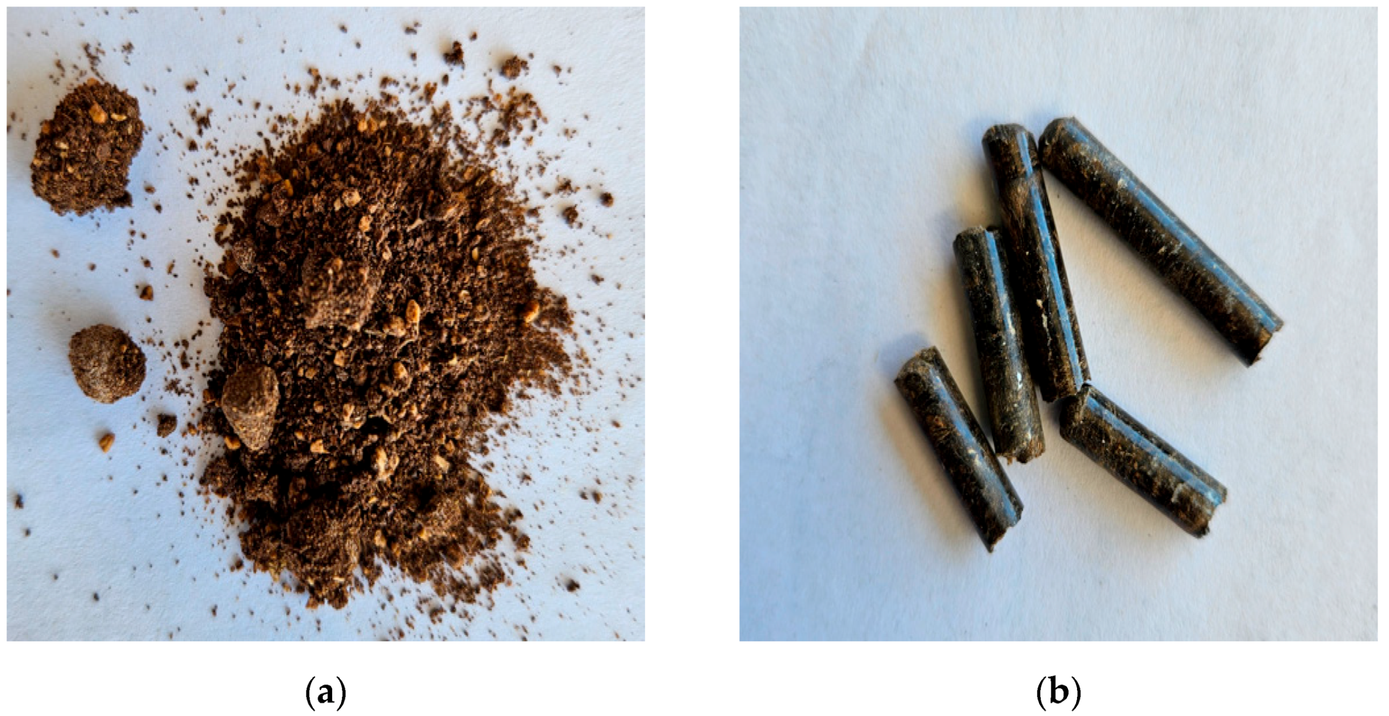
2.1. Raw Material Pretreatment

The olive pomace pellets used as raw material for the gasification plant were produced at the BioBIP Energia laboratory IPP Portalegre (Portugal) using an Andritz Simon-Heesen/HRV model v-3/75 pelletizer with 45 kw power, equipped with a cooling system for the pelletized material and a power and control panel. As can be observed in Figure 1a,b, where Figure 1a shows the raw material as received, and Figure 1b shows the produced pellets, the pellets have a cylindrical shape with a diameter of 6 mm and a length ranging from 16 mm to 30 mm.

2.2. Pellets of Olive Pomace and Gasification Product Analysis

2.2.1. Ultimate or Elemental Analysis

Elemental analysis, also referred to as ultimate analysis, is a method employed to determine the fundamental chemical composition of a given organic material. Through this process, the constituent elements are identified, with particular interest in nitrogen (N), carbon (C), hydrogen (H), sulfur (S), and oxygen (O). To quantify the amounts of these elements (C, H, N, S, and O), a Thermo Fisher Scientific Flash 2000 CHNS-O analyzer was utilized. This specific equipment from Thermo Fisher Scientific played a crucial role in measuring and determining the proportions of the mentioned elements within the sample under examination.

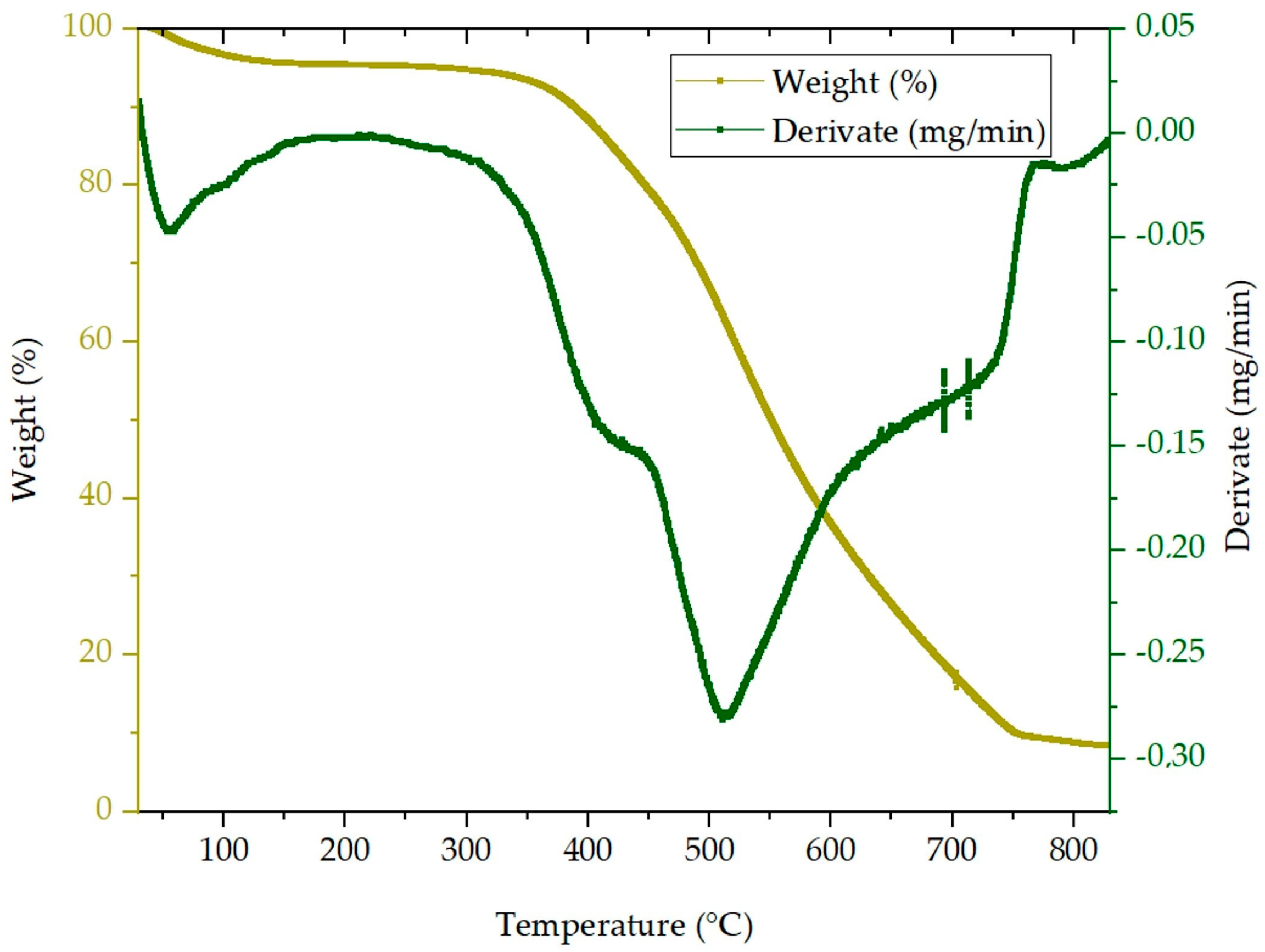
2.2.2. Proximate or Thermogravimetric Analysis

The concentration of the moisture, volatile matter, fixed carbon, and ash (or inorganic component) in the raw material samples was determined through thermogravimetric analysis, also known as proximate analysis. To carry out this analysis, a thermogravimetric analyzer PerkinElmer, model STA 6000, was used. The samples were heated at a rate of 20 °C per minute up to a temperature of 990 °C, with atmospheric air injected during the process. By examining the thermogravimetric profile, which depicts the change in sample mass in relation to temperature, the content of each material type was deduced by identifying the inflection points in the derivative of mass with respect to time.

2.2.3. X-ray Fluorescence (XRF)

In order to ascertain the viability of the process with respect to the presence of inorganic elements that may induce equipment corrosion and slag formation at high temperatures, X-ray fluorescence (XRF) analysis was employed to detect the concentration of said elements within the organic phase. The analysis was conducted utilizing a Thermo Scientific Niton XL 3T GoldD+ analyzer (Thermo Fisher Scientific, 168 Third Avenue, Waltham, MA 02451, USA).

2.2.4. Higher Heating Value Analysis (HHV)

The Higher Heating Value (HHV) of the byproducts or fuels was determined using the IKA C 2000 calorimetry equipment, which facilitates the complete combustion of the samples within an adiabatic environment. The HHV calculation involves measuring the total heat released during the complete combustion of the fuel, considering all the resulting products of this reaction. This value is crucial for assessing the energy generation capacity of the fuels and is typically expressed in units like kilocalories per kilogram (kcal/kg) or megajoules per kilogram (MJ/kg).

2.2.5. Gasification Performance

During the gasification experiments, two gasification reactors were utilized to compare hydrogen production in the syngas at different temperatures. The pilot-scale fixed-bed downdraft reactor with dimensions of 1500 mm height and 400 mm width is illustrated in Figure 2a. The gasification system comprises a fuel-storage hopper and a heat exchanger, wherein the recirculation of the reactor’s hot gases plays a pivotal role in both preheating the fuel and eliminating its moisture content. The reactor within this system is ingeniously compartmentalized into four well-defined zones. Commencing with the uppermost drying zone, the fuel material undergoes meticulous heating to expunge any moisture present. Subsequently, in the middle region, known as the pyrolysis zone, the fuel material experiences devolatilization, liberating its volatile components in the form of gases. Descending to the lower section, precisely at the reactor throat, a number of combustion reactions unfold. This crucial zone is responsible for channeling the fuel and introducing the oxidizing agent, thereby bestowing the requisite thermal energy for the gasification process. Finally, the reactor culminates in the reduction zone, where the fascinating formation of chars takes place. These solid particles result from the partial oxidation of the material and hold the pivotal role of facilitating the thermal cracking of gas products, transforming them into smaller, more valuable gaseous entities [25]. At the bottom of the reactor, a grate-shaped agitator is attached, designed to efficiently remove any unconverted material and ashes. This removal process is assisted by a feeder that transfers the collected residues to a separate container. The resulting gas product is extracted from the reactor at an approximate temperature of 500 °C and subsequently subjected to cleaning through a cyclone filter. Continuing its purification journey, the syngas passes through the previously mentioned heat exchanger. Additionally, it undergoes further purification through a particle filter, which comes in various sizes, allowing it to efficiently capture any remaining particulate matter and condensates. After the cleaning process is completed, the syngas is ready for use. It can be directly burned in a flare or introduced into an internal combustion engine, harnessing its potential energy for various applications.
Regarding the bubbling-bed reactor, this comprises a feeding system with a feeding mat and two storage silos (Figure 2b). The first silo can hold approximately 150 kg, while the second one can store up to 300 kg of fuel, and these are separated by butterfly-type pneumatic valves. The fuel is supplied to the reactor through a screw feeder located downstream from the silos and 30 cm above the bed base. The reactor is an upflow bubbling fluidized-bed type and it has a cylindrical shape with an internal diameter of 500 mm and stands 4150 mm high. This height is carefully chosen to optimize the fuel residence time, thus enhancing the conversion efficiency and preventing fuel entrainment by the gas flow [26]. At the reactor’s base, there are 36 concave air inlets, and the bed consists of approximately 50 kg of dolomite, which aids in tar conversion during the gasification process [27]. The raw material enters the reactor 20 cm above the bed base and commences its contact with the oxidizing agent and the dolomite. Following the reactor, there is a heat exchanger aimed at reducing the syngas temperature while simultaneously increasing the temperature of the oxidizing agent involved in the reaction. For the removal of unconverted material and ashes from the syngas, two cyclone filters are employed. Subsequently, the gas undergoes further purification through a condenser, where condensates and tars are retained.
Throughout the entire testing period of 420 min, meticulous monitoring and control were applied to various parameters. These included temperature and pressure levels, flow rates of the fuel and oxidizing agent, the quality and quantity of the produced syngas, as well as the quantities of byproducts, such as chars and tars.

2.2.6. Syngas Analysis by Gas Chromatography

During the experimental phase, syngas samples collected in Tedlar bags were subsequently subjected to analysis using the Varian 450GC gas chromatograph, an instrument equipped with a TCD detector capable of identifying and quantifying various gaseous elements present in the syngas samples. The Varian 450GC facilitates the detection and measurement of essential elements, including H2 (hydrogen), CO (carbon monoxide), O2 (oxygen), H2S (hydrogen sulfide), CO2 (carbon dioxide), N2 (nitrogen), CH4 (methane), and other short-chain hydrocarbons. This advanced analytical tool provides valuable insights into the composition of gases present in the syngas samples, enabling precise characterization and evaluation of its quality.

2.3. Predicted Performance Characteristics of the Syngas

2.3.1. Equivalence Ratio (ER)

The equivalence ratio (ER) is a fundamental concept in gasification and is defined as the ratio between the actual air/fuel ratio and the stoichiometric air/fuel ratio for complete conversion. This relationship is a crucial parameter in the gasification process, where air (or oxidizing agent) is introduced to interact with the fuel [28]. By varying the equivalence ratio, it is possible to control the amount of oxygen available for the reaction, directly affecting the efficiency of gasification and the composition of the produced syngas. An equivalence ratio below 1 indicates a fuel-rich mixture, while a ratio above 1 indicates an oxygen-rich mixture. In gasification, a range of 0.2 to 0.4 is desirable [29]. Typically, this term is employed in contexts involving insufficient air, such as in gasifiers, and can be mathematically represented by the following equation (Equation (1)):
E R = ( A / F ) A / F   s t o i c h i o m e t r i c
In this context, ER stands for the equivalence ratio, (A/F) represents the air–fuel ratio observed in the specific experimental conditions, and (A/F) stoichiometric denotes the air–fuel ratio at stoichiometric conditions. The equivalence ratio serves as a key performance indicator for the gasifier, as previously highlighted. Understanding the equivalence ratio is of paramount importance for optimizing gasification, ensuring an efficient and controlled process as well as obtaining syngas with the desired composition for specific applications.

2.3.2. Cold Gas Efficiency (CGE)

The gasification efficiency is measured by the Cold Gas Efficiency (CGE). This parameter represents the ratio of the total energy in the produced syngas to the total energy in the gasified fuel. In this study, CGE calculations are based on the Lower Heating Value (LHV), which accounts for the presence of water vapor in the synthesis gas and includes the fuel in the calculation. Therefore, it is essential to calculate the LHV of the fuel before determining the CGE [30].
To calculate the fuel’s Lower Heating Value (LHV), Equation (2) is utilized. This equation allows for the determination of the LHV value based on the energetic characteristics of the used fuel [30]:
L H V f u e l M J k g = H H V 0.212 × H 2 0.0245 × M o 0.008 × O 2
where LHVfuel is the Lower Heating Value of the olive pomace, HHV is the Higher Heating Value of the olive pomace obtained from the laboratory analysis, H2 is the percentage of hydrogen obtained in the ultimate analysis, Mo is the percentage of moisture in the olive pomace obtained in the proximate analysis, and O2 is a percentage of oxygen obtained in the ultimate analysis.
Equation (3) is used to define the CGE:
C G E   ( % ) = s y n g a s × L H V s y n g a s f u e l × L H V f u e l × 100
where ṁsyngas is the mass flow rate of the syngas produced and ṁfuel is the mass flow rate of the fuel, all in kg/h.

2.3.3. Syngas Yield

The syngas yield (ⴄsyngas) is a crucial parameter in gasification processes, quantifying the volumetric flow rate of the syngas produced per unit mass of the original fuel (Equation (4)) [31]:
s y n g a s   ( m 3 k g ) = v o l u m é t r i c   s y n g a s m a s s i c   f u e l
where ṁvolumetric syngas is the volume of syngas produced (Nm3/h) and ṁmassic is the mass of fuel gasified (kg/h).

2.3.4. Carbon Conversion Efficiency (CCE)

Carbon Conversion Efficiency (CCE) is a critical metric used to assess the effectiveness of a gasification or conversion process in transforming carbon-containing feedstocks into syngas. It quantifies the proportion of carbon present in the feedstock that has been successfully converted into syngas, as expressed in Equation (5) [32].
C C E   ( % ) = s y n g a s × 12 × [ %   C O + %   C O 2 + %   C H 4 + 2 × %   C 2 H 4 ] 22.4 × %   C s a m p l e × 100
To calculate the Carbon Conversion Efficiency, the volumetric percentages of carbon monoxide (CO), carbon dioxide (CO2), methane (CH4), and ethylene (C2H4) in the syngas are considered. Additionally, the mass percentage of elemental carbon (Csample) present in the original feedstock sample is considered.

3. Results

3.1. Olive Pomace Pellet Analysis

With the aim of understanding the quality and behavior of the fuel and ensuring proper preparation during the thermochemical process, several analyses were conducted to comprehend its characteristics. The results of these analyses, including the ultimate analysis, proximate analysis, XRF, and calorific value of the fuel under study, are presented in Table 1.

3.1.1. Ultimate Analysis

When comparing the fuel under study with the typical average values for coal, notable differences arise. It shows considerably higher H/C and O/C ratios and lower levels of nitrogen and sulfur [33]. The low sulfur content reduces the risk of acidic species forming, which could potentially harm the metal components of the gasification facility. While the olive pomace has a low nitrogen content, the likelihood of thermal NOx formation in the gasification is insignificant, given that the maximum observed temperature is 800 °C [34].

3.1.2. Proximate Analysis

The thermogravimetric analysis (TGA) curve (Figure 3) depicts the mass loss that occurs as the olive pomace sample is subjected to increasing temperature. The first stage of thermal degradation corresponds to an initial decrease in mass due to the water present in the sample, followed by a second loss derived from volatile compounds and a final loss related to fixed carbon, until it stabilizes at the ash content. In Figure 3, the derivative (DTG) curve is also presented, which not only illustrates the mass losses but also reflects the composition of the lignocellulosic source raw material; namely, the three main components: hemicellulose, cellulose, and lignin.
The slight change in sample mass between 30 °C and 120 °C was attributed to moisture evaporation, which corresponds to an approximately 4.5% mass loss. The pyrolytic decomposition of the sample began slowly around 335 °C, with the degradation rate increasing around 410 °C. This result indicates that higher activation energy is required to break down the olive pomace compared with, for instance, lignocellulosic biomass. This discrepancy could be explained by the higher lignin content as well as the oil extraction process that the olive pomace may have undergone [35]. The mass loss in this stage is approximately 58% and reflects the release of volatile material from the sample. Consequently, a comprehensive analysis of pyrolysis data revealed that, for slow heating rates, the decomposition of hemicellulose occurs in an initial phase, giving rise to a temperature peak at 400 °C, while the peak at 500 °C is attributed to cellulose decomposition [36]. The final decomposition, occurring at around 600 °C, is attributed to the degradation of the fixed carbon present in the sample. Since this carbon is primarily composed of lignin, which is an aromatic polymeric compound, it is highly stable and more resistant to breakdown compared with cellulose or hemicellulose [37].

3.1.3. X-ray Fluorescence (XRF)

Agro-industrial fuels frequently exhibit unfavorable characteristics attributed to the significant quantities of alkali and alkaline-earth metals, chlorine (Cl), and sulfur (S) within their composition. Consequently, despite the well-recognized advantages associated with the utilization of such biofuels, certain technical limitations persist, stemming from issues related to equipment corrosion, ash agglomeration, scaling, and slag formation. Among these concerns, the presence of alkali metals, specifically potassium (K) and sodium (Na), exerts the most pronounced influence on ash fusion during the thermochemical processes. Owing to the elevated concentration of potassium within the inorganic fraction of the raw material, the formation of potassium silicates, along with other potassium compounds (chlorides, sulfates, carbonates), occurs at relatively low temperatures, with the melting point of these potassium compounds estimated to be approximately 770 degrees Celsius [38].
The composition of the raw material, in terms of inorganic properties, exposed high concentrations of K and calcium (Ca). The melting temperature of the ash depends not only on the elemental composition of the ash but also on the inorganic fraction. In this case, the formation of K2SO4 causes slag accumulation on the high-temperature heating surfaces [39]. For this reason, and due to previous experiences [40], the present study refrained from gasifying at higher temperatures.

3.2. Gasification Parameters

Regarding olive pomace gasification in a fixed-bed reactor and a bubbling-bed reactor, Table 2 and Table 3 present the results obtained from experiments conducted to analyze the hydrogen yield in the syngas and the efficiency of this technology.
Temperature plays a crucial role in influencing the overall gasification reaction, impacting variables such as gas yield, carbon conversion efficiency (CCE), calorific value of the gas product, gas composition, and tar content. The relationship between the gas product concentration, gas yield, CCE, calorific value, and gas composition with regard to temperature is detailed in Table 2 and Table 3.
From an analysis of the syngas quality (Figure 4a,b), it was observed that these characteristics are highly similar as the temperature increases, with variations occurring only in the concentrations, which naturally influence the H2/CO ratio.
In a preliminary analysis, for both systems, it is possible to observe that the concentration of CO tends to increase with temperature, whereas the concentration of CO2 tends to increase only slightly. The increase in CO can be attributed to the endothermic Boudouard reaction (Equation (6)). The slight elevation in CO2 concentration is primarily due to the complete or partial exothermic oxidation reactions that are facilitated by the rise in temperature within the reactor and the subsequent increase in oxidizing agent (Equation (7)).
C + C O 2 2 C O ,               Δ H = + 172.0 K J / m o l
C + O 2 C O 2 ,               Δ H = 392.5 K J / m o l
The syngas analysis also showed that CH4 tends to decrease with increasing temperature, possibly also due to the small amount of volatiles (58.4%) present in the raw material; at the same time, there is an increase in H2. This observation may be related to the inverse of the exothermic reaction of methane formation (Equation (8)), when the temperature increases due to Le Chatelier’s principle.
Methane formation:
C O + 3 H 2 C H 4 + H 2 O     Δ H = 205.9 K J / m o l
As previously mentioned, an increase in the levels of H2 and CO is observed as the temperature is raised. It is noteworthy that the concentration rate of the H2 increase surpasses that of CO, underscoring that the H2/CO ratio in the gaseous product experiences a significant rise at higher temperature ranges within the context of a fixed-bed reactor [41]. However, in the scenario of a fluidized-bed reactor, the dynamics are reversed. Although the concentrations of these two constituents increase, the ascent in H2 concentration proves to be less pronounced compared with that for CO. This disparity results in a decrease in the H2/CO ratio as the temperature is elevated [42]. This phenomenon can be attributed to both the short residence time within the reactor and thermal cracking reactions, which are more prominent in the fixed-bed setup. In the latter, the product gas generated in the pyrolysis zone is compelled to traverse the carbonaceous structures formed in the oxidation zone, undergoing a reduction process.
It is manifestly apparent that any gasification process undergoes a preliminary pyrolysis phase, as expounded earlier. Throughout this stage, an assemblage of hydrocarbons materializes, encompassing entities such as C2H6, C2H4, and C2H2. Notably, C2H6 assumes the role of an intermediary product, poised to engender lighter hydrocarbons and hydrogen (as described in Equation (9)).
Ethane pyrolysis:
C 2 H 6 C 2 H 4 + H 2     Δ H = + 32.9 K J / m o l
In Figure 5a,b, a discernible pattern emerges wherein the concentrations of these constituents achieve their zenith at a temperature of 750 °C for both reactors. Subsequently, as the temperature escalates, there is a gradual diminution in their concentrations, thereby giving rise to an increase in the concentration of H2. In a parallel manner, similar to the behavior of C2H6, C2H4 likewise functions as an intermediary entity that undergoes pyrolysis, ultimately yielding C2H2 and H2, as depicted in Equation (10) [43].
Ethane pyrolysis:
C 2 H 4 C 2 H 2 + H 2     Δ H = + 39.7 K J / m o l
The preceding reactions are endothermic in nature, and, as a consequence, they exhibit a propensity to increase as the temperature intensifies, leading to an elevation in the concentration of H2 molecules and hydrocarbons with shorter carbon chains [44]. Analogously, a parallel phenomenon is observed in the case of CH4, which undergoes thermal cracking in direct correlation with the progressive elevation in temperature [45].
Concerning parameters indicative of gasification performance in both reactors, it is discernible from Figure 6a,b that the Lower Heating Value (LHV), Cold Gas Efficiency (CGE), syngas yield, and Carbon Conversion Efficiency (CCE) parameters exhibit a consistent trend: as the temperature rises, the LHV and CGE of the syngas register a decrement in both reactors, while conversely, the CCE and syngas yield manifest an inverse relationship.
The observed decline in the LHV accompanied by an increase in the Carbon Conversion Efficiency (CCE) can be attributed to the near-complete oxidation of the feedstock, thereby engendering an escalation in CO2 levels while concurrently precipitating a reduction in the concentration of hydrocarbon gases possessing elevated calorific potency. In the CGE, barring any significant alteration in gas product yield, the escalation in temperature precipitates a diminishment in the LHV. Consequently, an anticipatable outcome entails a concomitant reduction in CGE, as this metric is intricately contingent upon the LHV of the resultant gas composition.

4. Discussion

Regarding the comparative analysis between the two olive pomace pellet gasification systems, substantial disparities come to light, particularly with respect to the hydrogen yield (H2/CO ratio), syngas LHV, byproduct formation (chars and tars), Equivalence Ratio (ER), and performance parameters.
In the conducted experiment, the production of hydrogen (H2) was examined across varying temperatures and within two types of reactors: fixed bed and bubbling fluidized bed. Temperature assumes a pivotal role in chemical reactions, particularly in the context of hydrogen production. The findings demonstrate that at a temperature of 800 °C, the maximum yield of H2 was achieved, exhibiting an efficiency of 16.52%. This implies that the higher temperature facilitated more favorable conditions for the thermal cracking chemical reaction [46]. Furthermore, the distribution of hydrogen production between the two reactor types differed. The bubbling fluidized-bed reactor yielded an efficiency of 12.97%, whereas the fixed-bed reactor produced 16.52% hydrogen. This disparity implies that reactor characteristics, such as mass and heat transfer, could exert an influence on hydrogen production under varying conditions [47,48]. The H2/CO ratio, which represents the proportion between the quantities of hydrogen and carbon monoxide produced, was also assessed at different temperatures and reactor types. The H2/CO ratio holds significance as it indicates the composition of the synthesized gas produced and may serve as an indicator of the efficiency of the hydrogen production process. The H2/CO ratio was determined to be 0.87 at a temperature of 750 °C in the bubbling fluidized-bed reactor and 0.93 at a temperature of 800 °C in the fixed-bed reactor. These values closely resemble those obtained in the references cited [49,50,51] and suggest that, as the temperature increases, the proportion of hydrogen relative to carbon monoxide also rises, particularly in the fixed-bed reactor. This occurrence can be explained by alterations in reaction kinetics and the thermodynamic properties of the reactions involved in hydrogen production, namely thermal cracking [52].
Regarding the Lower Heating Value of the syngas, it is noteworthy that the values obtained in the fixed-bed experiments are comparatively lower than those observed in the trials conducted with the bubbling fluidized bed [53]. This observation can be attributed to the reduced production of hydrocarbons, particularly methane and ethylene. In the fixed-bed configuration, due to the lack of uniform temperature distribution across the bed, distinct zones arise where exothermic reactions prevail; consequently, this leads to enhanced hydrocarbon cracking, resulting in lower concentrations of these compounds within the syngas composition [54].
With regard to the parameter “Equivalence Ratio” (ER) and its implications in bubbling fluidized-bed and fixed-bed systems, this parameter emerges as a critical indicator for assessing the relationship between the actual amount of oxidizing agent and the theoretical amount of oxidizing agent required for a chemical or complete combustion reaction. Through multiple trials, it has been observed that the ER value in the bubbling fluidized-bed system is consistently higher (0.23) compared with the value obtained in the fixed bed (maximum 0.21). This phenomenon implies that the bubbling fluidized-bed configuration influences the composition of the reactive mixture, leading to a relatively higher condition of fuel excess in the bubbling fluidized-bed system. The studies conducted by Barea et al. [55] and Oliveira et al. [56] further support this observation, emphasizing the reproducibility and consistency of this behavior. An intriguing feature is the higher energy demand necessary to maintain uniform temperature in a bubbling fluidized-bed reactor compared to a fixed bed. This can be attributed to the complex dynamics of bubbling fluidized particles, where continuous particle movement necessitates a more substantial energy input to maintain thermal homogeneity. Conversely, even with an increase in temperatures, the fixed bed fails to approach the ER values obtained in the bubbling fluidized bed, as indicated in the referenced study [57]. This suggests that factors beyond temperature, such as mixing efficiency and reactant distribution, play a significant role in the observed discrepancies in ER values. Specifically, an investigation into the LHV behavior within the fixed-bed configuration reveals a noteworthy decrease, accompanied by an escalation in the Equivalence Ratio from 5.7 to 4.82 MJ/Nm3. This aspect potentially finds its origin in subtle decrements within the concentration of light hydrocarbons, conceivably instigated by the thermal cracking of tar constituents. These hydrocarbons, characterized by their elevated calorific value, stand in contrast to hydrogen and carbon monoxide, both of which exhibited augmentation in response to escalating temperature and ER. Within the bubbling fluidized-bed system, a parallel scenario unfolds, where the LHV drops from 6.93 to 5.37 MJ/Nm3. Here, a comparable trend is observed, wherein there is an accrual of hydrogen and carbon monoxide species with the increase in temperature and the ER. This phenomenon speaks to a significant capitalization of these gaseous constituents, potentially reflecting an intricate interplay of bubbling-fluidized particle dynamics and chemical reactivity [58].
The generation of tars exhibits a higher propensity within the bubbling fluidized-bed configuration when contrasted with the fixed-bed system. This phenomenon has been substantiated by several researchers [58,59,60], attributing such behavior to the comparatively shorter residence time of the fuel within the bubbling fluidized-bed reactor and the heightened thermal cracking experienced by the syngas within the fixed-bed process. The latter arises due to the descending flow pattern, necessitating the syngas to traverse through high-temperature unconverted material (chars). Nevertheless, a pivotal distinction between the two systems is discerned in the bubbling fluidized-bed configuration, wherein a dedicated tar collection mechanism is embedded, diverging from the fixed-bed arrangement. Within the bubbling fluidized-bed system, a condenser comprising three modules, circulated with a cooled fluid via a radiator, serves to temper the produced syngas and capture all the condensable constituents. A salient contributor to the reduction in tars within the bubbling fluidized-bed system is the incorporation of a catalyst (dolomite), which engenders an enhanced fuel-to-air mixture while concurrently decomposing heavy hydrocarbons. The porous structure of this catalyst facilitates the adsorption of said hydrocarbons, thereby instigating the formation of less stable species susceptible to facile decomposition. As concerns the char production aspect, the bubbling fluidized-bed system manifests diminished values compared with its fixed-bed counterpart. This discrepancy may be linked to the dimensions of the bubbling fluidized-bed reactor and the density of chars, which are efficiently evacuated based on density contrasts, in contradistinction to the fixed-bed arrangement characterized by a dedicated char removal apparatus [61,62]. These investigations collectively contribute to an enriched comprehension of the intricate interplay between process parameters, bed dynamics, and the resulting product distributions in bubbling fluidized and fixed-bed configurations.
This comprehensive analysis underscores the conspicuous influence exerted by the factors elucidated hitherto upon the reactor’s performance parameters, particularly the Cold Gas Efficiency (CGE) and the Carbon Conversion Efficiency (CCE). It is discerned that the CGE assumes higher values within the bubbling fluidized-bed configuration, owing to its propensity for syngas generation. However, this trend is characterized by a diminishing trajectory with escalating temperature in both reactor types. Concomitantly, the CCE exhibits a more pronounced augmentation within the bubbling fluidized-bed system, an attribute ascribed to its intrinsic design attributes that foster enhanced reactivity. Moreover, the CCE is noted to exhibit a direct correlation with temperature elevation in both bubbling fluidized and fixed-bed reactors, thereby underscoring the temperature-dependent kinetics governing carbon conversion efficiencies [63]. This amalgamation of empirical observations substantially contributes to an enriched comprehension of the intricate interplay between process parameters, bed dynamics, and resultant performance metrics within the distinct operational frameworks of bubbling fluidized and fixed-bed reactors.

5. Conclusions

The present investigation was dedicated to the thorough examination of thermal gasification in two distinct reactors, namely a bubbling fluidized-bed reactor and a downdraft fixed-bed reactor, utilizing olive pomace biomass in pellet form. The study encompassed a range of temperatures (700, 750, and 800 °C), with the overarching objective of elucidating optimal conditions conducive to the generation of a cleaner and more hydrogen-enriched syngas. The ensuing conclusions, derived from meticulous analysis, are delineated as follows:
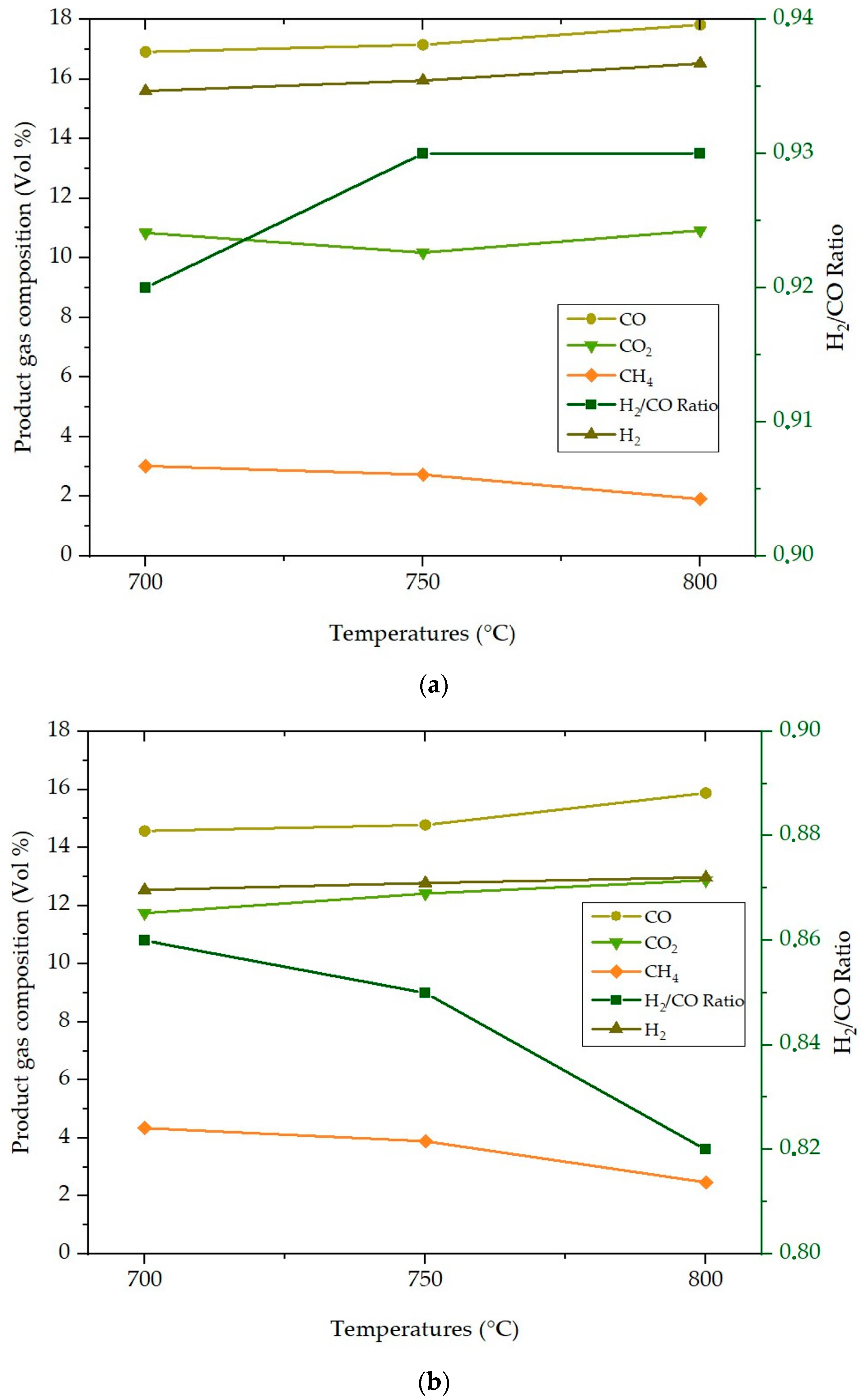
  • Optimal conditions, in terms of hydrogen concentration, were manifest at an operating temperature of 800 °C, yielding concentrations of 12.97 vol.% within the bubbling fluidized-bed reactor and 16.52 vol.% within the fixed-bed reactor.
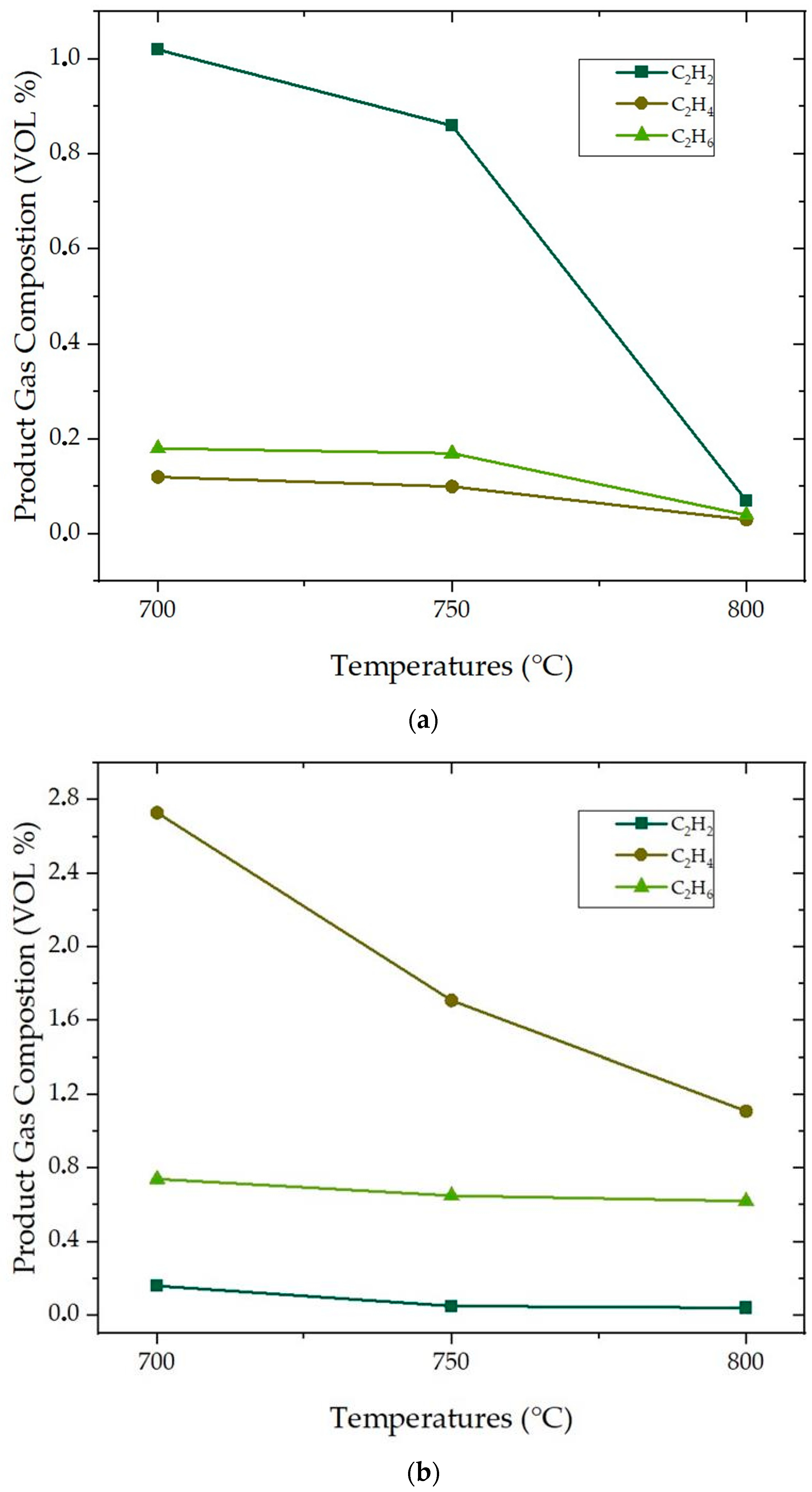
  • A conspicuous trend emerged within both reactor configurations, wherein escalating operational temperatures precipitated a reduction in hydrocarbons and CH4, concomitant with an elevation in H2, CO, and CO2 concentrations.
  • The diminishing trajectory of condensate content was observed in tandem with increasing temperature and Equivalence Ratio (ER). This phenomenon finds its etiology in the augmented thermal cracking of tar constituents. Notably, the char yield exhibited a decrement from 38 to 33 g/kg fuel within the bubbling fluidized bed and from 65 to 55 g/kg fuel within the fluidized-bed reactor, corresponding to heightened operating temperatures and ERs.
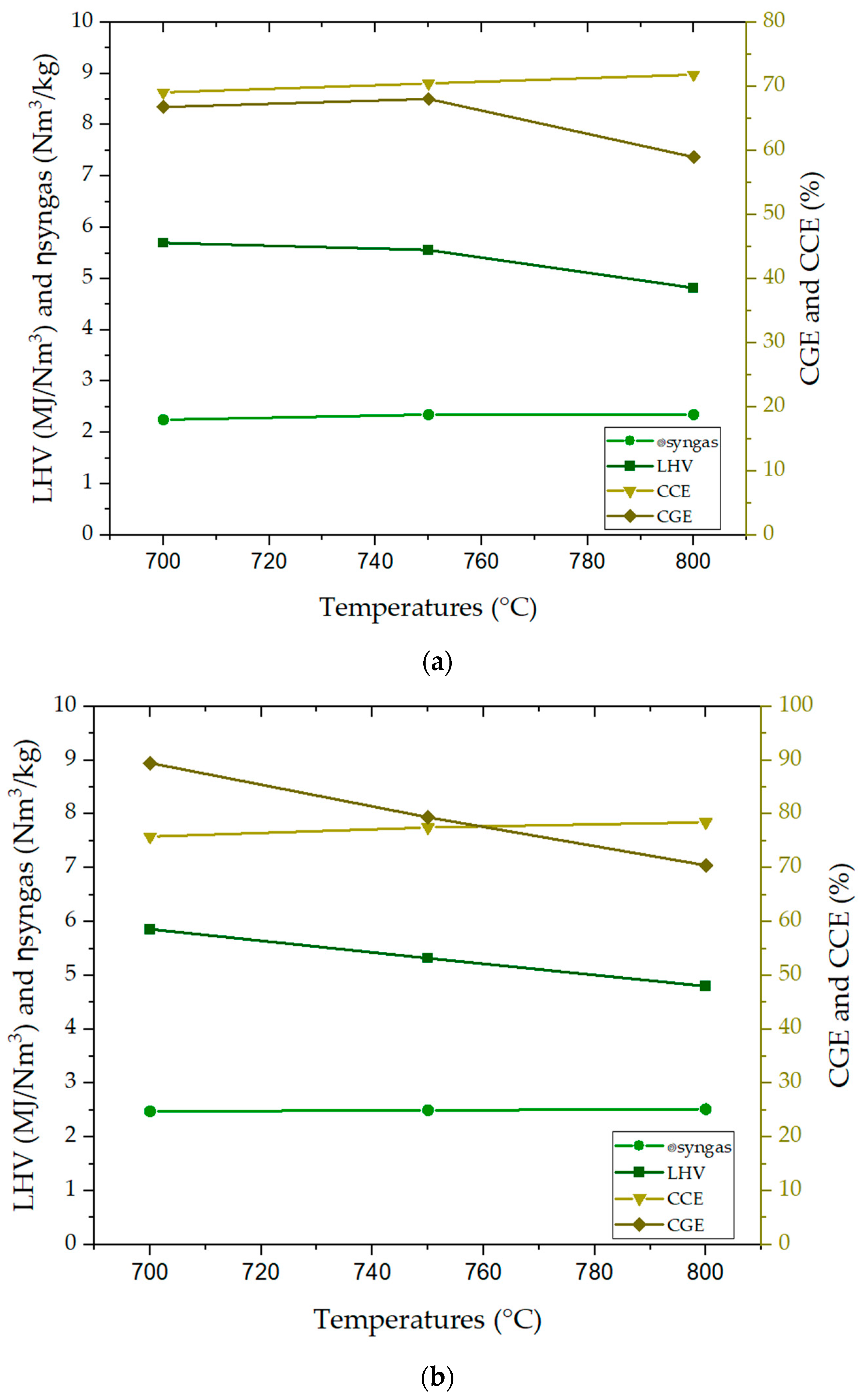
  • Pertaining to the performance metrics of the distinct reactor paradigms, syngas yield demonstrated an escalating trend aligned with increasing temperature, a behavior mirrored in the Carbon Conversion Efficiency (CCE). Conversely, the Cold Gas Efficiency (CGE) displayed a diminishing trend, primarily attributed to the thermal cracking of hydrocarbons, exerting an adverse influence upon the Lower Heating Value (LHV).
From the point of view of hydrogen production, it is worth highlighting that the fixed-bed cracking process has advantages over the fluidized-bed cracking process. The fixed-bed configuration tends to produce higher concentrations of hydrogen, indicating superior hydrogen selectivity under specific operating conditions, such as elevated temperatures. However, it is important to recognize that the fluidized-bed reactor produces more synthesis gas in general, and for this reason, it can present a good alternative for the production of hydrogen as well. Therefore, there is a trade-off between hydrogen concentration and total syngas production when considering these two types of reactors for hydrogen generation.
The findings encapsulated above bear intrinsic significance as fundamental baseline data, amenable for the realization of hydrogen production via agro-industrial byproducts within the realms of pilot-scale and demonstrative implementations. It is, however, imperative to exercise caution in deploying this technology for hydrogen production without the incorporation of an efficient cleansing system capable of complete tar removal. Such a system is imperative to preserve the integrity of indispensable equipment employed for subsequent separation processes, such as Pressure Swing Adsorption (PSA) units.

Author Contributions

Conceptualization, L.C.-C., J.L.C.-H., P.B., J.T.-C. and M.J.H.-O.; methodology, L.C.-C.; software, L.C.-C.; validation, L.C.-C., J.L.C.-H., P.B., J.T.-C. and M.J.H.-O.; formal analysis, L.C.-C., J.L.C.-H., P.B., J.T.-C. and M.J.H.-O.; investigation L.C.-C., J.L.C.-H., P.B., J.T.-C. and M.J.H.-O.; resources, L.C.-C.; data curation, L.C.-C.; writing—original draft preparation, L.C.-C. and D.D.-P.; writing—review and editing, L.C.-C. and D.D.-P.; visualization, L.C.-C. and D.D.-P.; supervision, J.L.C.-H., P.B., J.T.-C. and M.J.H.-O.; project administration, L.C.-C.; funding acquisition, J.L.C.-H., P.B., J.T.-C. and M.J.H.-O. All authors have read and agreed to the published version of the manuscript.

Funding

This research received no external funding.

Conflicts of Interest

The authors declare no conflict of interest.

References

  1. Hu, B.; Liu, X.R.; Chen, H.Z.; Liu, J.; Wu, Y.W.; Zhao, L.; Zhang, B.; Lu, Q. The selective adsorption mechanism of CO2 from biomass pyrolysis gas on N-doped carbon materials with an electric field: A first-principles study. J. Energy Inst. 2023, 109, 101301. [Google Scholar] [CrossRef]
  2. Tezer, Ö.; Karabağ, N.; Öngen, A.; Çolpan, C.Ö.; Ayol, A. Biomass gasification for sustainable energy production: A review. Int. J. Hydrogen Energy 2022, 47, 15419–15433. [Google Scholar] [CrossRef]
  3. Tsakiridis, P.E.; Samouhos, M.; Perraki, M. Valorization of Dried Olive Pomace as an alternative fuel resource in cement clinkerization. Constr. Build. Mater. 2017, 153, 202–210. [Google Scholar] [CrossRef]
  4. Yi, W.; Wang, X.; Zeng, K.; Yang, H.; Shao, J.; Zhang, S.; Chen, H. Improving the staged gasification of crop straw by choosing a suitable devolatilization temperature. J. Energy Inst. 2023, 108, 101221. [Google Scholar] [CrossRef]
  5. Aguado, R.; Escámez, A.; Jurado, F.; Vera, D. Experimental assessment of a pilot-scale gasification plant fueled with olive pomace pellets for combined power, heat and biochar production. Fuel 2023, 344, 128127. [Google Scholar] [CrossRef]
  6. Tumuluru, J.S. Effect of pellet die diameter on density and durability of pellets made from high moisture woody and herbaceous biomass. Carbon Resour. Convers. 2018, 1, 44–54. [Google Scholar] [CrossRef]
  7. Martelo, N.; Antxustegi, M.; Corro, E.; Baloch, M.; Volpe, R.; Gagliano, A.; Fichera, A.; Alriols, M.G. Use of residual lignocellulosic biomass for energetic uses and environmental remediation through pyrolysis. Energy Storage Sav. 2022, 1, 129–135. [Google Scholar] [CrossRef]
  8. Greenhall, J.; Pantea, C.; Vakhlamov, P.; Davis, E.S.; Semelsberger, T. Data-driven acoustic measurement of moisture content in flowing biomass. Mach. Learn. Appl. 2023, 13, 100476. [Google Scholar] [CrossRef]
  9. Karaca, A.E.; Qureshy, A.M.M.I.; Dincer, I. An overview and critical assessment of thermochemical hydrogen production methods. J. Clean. Prod. 2023, 385, 135706. [Google Scholar] [CrossRef]
  10. Sołowski, G.; Shalaby, M.; Özdemir, F.A. Plastic and Waste Tire Pyrolysis Focused on Hydrogen Production—A Review. Hydrogen 2022, 3, 531–549. [Google Scholar] [CrossRef]
  11. Minami, E.; Miyamoto, T.; Kawamoto, H. Decomposition of Saccharides and Alcohols in Solution Plasma for Hydrogen Production. Hydrogen 2022, 3, 333–347. [Google Scholar] [CrossRef]
  12. Ram, N.K.; Raman, P.; Khan, A.; Kumar, A. Financial viability of hydrogen-enriched gas produced adopting air-steam gasification for power generation: A detailed comparative study and sensitivity analysis with air gasification systems. Bioresour. Technol. Rep. 2023, 22, 101387. [Google Scholar] [CrossRef]
  13. Hussein, M.S.; Burra, K.G.; Amano, R.S.; Gupta, A.K. Temperature and gasifying media effects on chicken manure pyrolysis and gasification. Fuel 2017, 202, 36–45. [Google Scholar] [CrossRef]
  14. Kruusement, K.; Luik, H.; Waldner, M.; Vogel, F.; Luik, L. Gasification and liquefaction of solid fuels by hydrothermal conversion methods. J. Anal. Appl. Pyrolysis 2014, 108, 265–273. [Google Scholar] [CrossRef]
  15. Chen, J.; Wang, C.; Shang, W.; Bai, Y.; Wu, X. Study on the mechanisms of hydrogen production from alkali lignin gasification in supercritical water by ReaxFF molecular dynamics simulation. Energy 2023, 278, 127900. [Google Scholar] [CrossRef]
  16. Bai, M.; Huo, E.; Sun, Y.; Wang, S.; Zhao, Y.; Zhang, Q.; Wang, C.; Zou, R.; Qian, M.; Lei, H. Supercritical water co-gasification mechanism of lignin and low density polyethylene into syngas: ReaxFF molecular dynamic simulation and density functional theory calculation study. Fuel Process. Technol. 2023, 250, 107877. [Google Scholar] [CrossRef]
  17. Tezer, Ö.; Karabağ, N.; Öngen, A.; Ayol, A. Gasification performance of olive pomace in updraft and downdraft fixed bed reactors. Int. J. Hydrogen Energy 2023, 48, 22909–22920. [Google Scholar] [CrossRef]
  18. Ducom, G.; Tagutchou, J.P.; Gautier, M.; Gaignaire, C.; Méhu, J.; Gourdon, R. Olive mill solid waste gasification in a pilot-scale downdraft gasifier with three-stage air supply: Performance, mass-energy balance and fate of inorganic elements. Fuel 2023, 340, 127469. [Google Scholar] [CrossRef]
  19. Gálvez-Pérez, A.; Martín-Lara, M.A.; Calero, M.; Pérez, A.; Canu, P.; Blázquez, G. Experimental investigation on the air gasification of olive cake at low temperatures. Fuel Process. Technol. 2021, 213, 106703. [Google Scholar] [CrossRef]
  20. Soares, J.; Oliveira, A.C. Experimental assessment of pine wood chips gasification at steady and part-load performance. Biomass Bioenergy 2020, 139, 105625. [Google Scholar] [CrossRef]
  21. Patel, V.R.; Upadhyay, D.S.; Patel, R.N. Gasification of lignite in a fixed bed reactor: Influence of particle size on performance of downdraft gasifier. Energy 2014, 78, 323–332. [Google Scholar] [CrossRef]
  22. Leung, D.Y.C.; Wang, C.L. Fluidized-bed gasification of waste tire powders. Fuel Process. Technol. 2003, 84, 175–196. [Google Scholar] [CrossRef]
  23. Warnecke, R. Gasification of biomass: Comparison of fixed bed and fluidized bed gasifier. Biomass Bioenergy 2000, 18, 489–497. [Google Scholar] [CrossRef]
  24. Rezaei, H.; Tajilrou, M.; Lee, J.S.; Singaraveloo, K.; Lau, A.; Sokhansanj, S. Evolution of biomass particles during pelletization process. Particuology 2024, 86, 182–187. [Google Scholar] [CrossRef]
  25. Khonde, R.; Chaurasia, A. Rice husk gasification in a two-stage fixed-bed gasifier: Production of hydrogen rich syngas and kinetics. Int. J. Hydrog. Energy 2016, 41, 8793–8802. [Google Scholar] [CrossRef]
  26. Priya, C. Sande and Saumi Ray Fine Mesh Computational Fluid Dynamics Study on Gas-Fluidization of Geldart A Particles: Homogeneous to Bubbling Bed. Ind. Eng. Chem. Res. 2016, 55, 2623–2633. [Google Scholar]
  27. Phuakpunk, K.; Chalermsinsuwan, B.; Putivisutisak, S.; Assabumrungrat, S. Simulations of sorbent regeneration in a circulating fluidized bed system for sorption enhanced steam reforming with dolomite. Particuology 2020, 50, 156–172. [Google Scholar] [CrossRef]
  28. Nguyen, N.M.; Alobaid, F.; May, J.; Peters, J.; Epple, B. Experimental study on steam gasification of torrefied woodchips in a bubbling fluidized bed reactor. Energy 2020, 202, 117744. [Google Scholar] [CrossRef]
  29. Agu, C.E.; Moldestad, B.M.E.; Pfeifer, C. Assessment of Combustion and Gasification Behavior in a Bubbling Fluidized Bed Reactor: A Comparison between Biomass with and without Chemical Additives. Energy Fuels 2020, 34, 9654–9663. [Google Scholar] [CrossRef]
  30. Kwon, S.; Im, S. kyun Feasibility of non-thermal plasma gasification for a waste-to-energy power plant. Energy Convers. Manag. 2022, 251, 114978. [Google Scholar] [CrossRef]
  31. Ayub, Y.; Hu, Y.; Ren, J. Estimation of syngas yield in hydrothermal gasification process by application of artificial intelligence models. Renew. Energy 2023, 215, 118953. [Google Scholar] [CrossRef]
  32. Mariyam, S.; Shahbaz, M.; Al-Ansari, T.; Mackey, H.R.; McKay, G. A critical review on co-gasification and co-pyrolysis for gas production. Renew. Sustain. Energy Rev. 2022, 161, 112349. [Google Scholar] [CrossRef]
  33. Ramakrishnan, P.; Singh, J.K.; Sahoo, A.; Mohapatra, S.S. Cfd Simulation for Coal Gasification in Fluidized Bed Gasifier. SSRN Electron. J. 2022, 281, 128272. [Google Scholar]
  34. Raj, R.; Tirkey, J.V.; Singh, D.K.; Jena, P. Co-gasification of waste triple feed-material blends using downdraft gasifier integrated with dual fuel diesel engine: An RSM-based comparative parametric optimization. J. Energy Inst. 2023, 109, 101271. [Google Scholar] [CrossRef]
  35. Felix, C.B.; Chen, W.H.; Ubando, A.T.; Park, Y.K.; Lin, K.Y.A.; Pugazhendhi, A.; Nguyen, T.B.; Dong, C. Di A comprehensive review of thermogravimetric analysis in lignocellulosic and algal biomass gasification. Chem. Eng. J. 2022, 445, 136730. [Google Scholar] [CrossRef]
  36. Burhenne, L.; Messmer, J.; Aicher, T.; Laborie, M.P. The effect of the biomass components lignin, cellulose and hemicellulose on TGA and fixed bed pyrolysis. J. Anal. Appl. Pyrolysis 2013, 101, 177–184. [Google Scholar] [CrossRef]
  37. Kuo, P.C.; Sun, Z.; Özdemir, F.; Aziz, M.; Wu, W. CO2 utilization in chemical looping gasification and co-gasification of lignocellulosic biomass components over iron-based oxygen carriers: Thermogravimetric behavior, synergistic effect, and reduction characteristics. J. Environ. Chem. Eng. 2023, 11, 109971. [Google Scholar] [CrossRef]
  38. Čepauskiene, D.; Pedišius, N.; Milčius, D. Chemical composition of agromass ash and its influence on ash melting characteristics. Agron. Res. 2018, 16, 357–364. [Google Scholar]
  39. Niu, Y.; Tan, H.; Wang, X.; Liu, Z.; Liu, H.; Liu, Y.; Xu, T. Study on fusion characteristics of biomass ash. Bioresour. Technol. 2010, 101, 9373–9381. [Google Scholar] [CrossRef]
  40. Horák, J.; Kuboňová, L.; Dej, M.; Laciok, V.; Tomšejová, Š.; Hopan, F.; Krpec, K.; Koloničný, J. Effects of the type of biomass and ashing temperature on the properties of solid fuel ashes. Pol. J. Chem. Technol. 2019, 21, 43–51. [Google Scholar] [CrossRef]
  41. Zeng, J.; Xiao, R.; Zeng, D.; Zhao, Y.; Zhang, H.; Shen, D. High H2/CO Ratio Syngas Production from Chemical Looping Gasification of Sawdust in a Dual Fluidized Bed Gasifier. Energy Fuels 2016, 30, 1764–1770. [Google Scholar] [CrossRef]
  42. Mazhar, A.; Khoja, A.; Azad, A.; Mushtaq, F.; Naqvi, S.; Shakir, S.; Hassan, M. Performance Analysis of TiO2-Modified Co/MgAl2O4 Catalyst for Dry Reforming of Methane in a Fixed Bed Reactor for Syngas (H2, CO) Production. Energies 2021, 14, 3347. [Google Scholar] [CrossRef]
  43. Moldoveanu, S.C. Chapter 2—Pyrolysis of Hydrocarbons. In Pyrolysis of Organic Molecules, 2nd ed.; Elsevier: Amsterdam, The Netherlands, 2019; pp. 35–161. ISBN 9780444640000. [Google Scholar]
  44. Esfahani, R.A.M.; Osmieri, L.; Specchia, S.; Yusup, S.; Tavasoli, A.; Zamaniyan, A. H2-rich syngas production through mixed residual biomass and HDPE waste via integrated catalytic gasification and tar cracking plus bio-char upgrading. Chem. Eng. J. 2017, 308, 578–587. [Google Scholar] [CrossRef]
  45. Wang, K.; Villano, S.M.; Dean, A.M. Fundamentally-based kinetic model for propene pyrolysis. Combust. Flame 2015, 162, 4456–4470. [Google Scholar] [CrossRef]
  46. Álvarez-Bermúdez, C.; Anca-Couce, A.; Chapela, S.; Scharler, R.; Buchmayr, M.; Gómez, M.Á.; Porteiro, J. Validation of a biomass conversion mechanism by Eulerian modelling of a fixed-bed system under low primary air conditions. Renew. Energy 2023, 215, 119003. [Google Scholar] [CrossRef]
  47. Singh, A.; Shivapuji, A.M.; Dasappa, S. Hydrogen production through agro-residue gasification and adsorptive separation. Appl. Therm. Eng. 2023, 234, 121247. [Google Scholar] [CrossRef]
  48. Njuguna, F.I.; Ndiritu, H.M.; Gathitu, B.B.; Hawi, M.; Munyalo, J.M. Experimental investigation and optimization of the gasification parameters of macadamia nutshells in a batch-fed bubbling fluidized bed gasifier with air preheating. Energy Storage Sav. 2023. [Google Scholar] [CrossRef]
  49. Qin, W.; Chen, S.; Ma, B.; Wang, J.; Li, J.; Liang, R.; Xu, Z.; Liu, L.; Dong, C.; Zhang, H. Methanol solution promoting cotton fiber chemical looping gasification for high H2/CO ratio syngas. Int. J. Hydrog. Energy 2019, 44, 7149–7157. [Google Scholar] [CrossRef]
  50. Lampropoulos, A.; Zubillaga, I.G.; Pérez-Vega, R.; Ntavos, N.; Fallas, Y.; Varvoutis, G. Preliminary Experimental Results and Modelling Study of Olive Kernel Gasification in a 2 MWth BFB Gasifier. Processes 2022, 10, 2020. [Google Scholar] [CrossRef]
  51. Cullen, J.; Kang, K.; Klinghoffer, N.B. Syngas Quality Enhancement by CO2 Injection during the Co-Gasification of Biomass and Plastic. Ind. Eng. Chem. Res. 2023, 62, 12085–12095. [Google Scholar] [CrossRef]
  52. Patuzzi, F.; Basso, D.; Vakalis, S.; Antolini, D.; Piazzi, S.; Benedetti, V.; Cordioli, E.; Baratieri, M. State-of-the-art of small-scale biomass gasification systems: An extensive and unique monitoring review. Energy 2021, 223, 120039. [Google Scholar] [CrossRef]
  53. Guardo, A.; Coussirat, M.; Recasens, F.; Larrayoz, M.A.; Escaler, X. CFD study on particle-to-fluid heat transfer in fixed bed reactors: Convective heat transfer at low and high pressure. Chem. Eng. Sci. 2006, 61, 4341–4353. [Google Scholar] [CrossRef]
  54. Gómez-Barea, A.; Arjona, R.; Ollero, P. Pilot-Plant Gasification of Olive Stone: A Technical Assessment. Energy Fuels 2005, 19, 598–605. [Google Scholar] [CrossRef]
  55. Oliveira, M.; Ramos, A.; Monteiro, E.; Rouboa, A. Modeling and simulation of a fixed bed gasification process for thermal treatment of municipal solid waste and agricultural residues. Energy Rep. 2021, 7, 256–269. [Google Scholar] [CrossRef]
  56. Zang, G.; Jia, J.; Shi, Y.; Sharma, T.; Ratner, A. Modeling and economic analysis of waste tire gasification in fluidized and fixed bed gasifiers. Waste Manag. 2019, 89, 201–211. [Google Scholar] [CrossRef]
  57. Udomsirichakorn, J.; Basu, P.; Salam, P.A.; Acharya, B. Effect of CaO on tar reforming to hydrogen-enriched gas with in-process CO2 capture in a bubbling fluidized bed biomass steam gasifier. Int. J. Hydrog. Energy 2013, 38, 14495–14504. [Google Scholar] [CrossRef]
  58. Pang, S. 9-Fuel flexible gas production: Biomass, coal and bio-solid wastes. In Fuel Flexible Energy Generation Solid, Liquid and Gaseous Fuels; Woodhead Publishing: Cambridgeshire, UK, 2016; pp. 241–269. [Google Scholar]
  59. Speight, J.G. 2-Types of gasifier for synthetic liquid fuel production: Design and technology. In Gasification for Synthetic Fuel Production; Fundamentals, Processes and Applications Woodhead Publishing Series in Energy; Woodhead Publishing: Cambridgeshire, UK, 2015; pp. 29–55. [Google Scholar]
  60. Gómez-Barea, A.; Ollero, P.; Leckner, B. Optimization of char and tar conversion in fluidized bed biomass gasifiers. Fuel 2013, 103, 42–52. [Google Scholar] [CrossRef]
  61. Van De Steene, L.; Tagutchou, J.P.; Mermoud, F.; Martin, E.; Salvador, S. A new experimental Continuous Fixed Bed Reactor to characterise wood char gasification. Fuel 2010, 89, 3320–3329. [Google Scholar] [CrossRef]
  62. Quintero-Coronel, D.A.; Lenis-Rodas, Y.A.; Corredor, L.; Perreault, P.; Bula, A.; Gonzalez-Quiroga, A. Co-gasification of biomass and coal in a top-lit updraft fixed bed gasifier: Syngas composition and its interchangeability with natural gas for combustion applications. Fuel 2022, 316, 123394. [Google Scholar] [CrossRef]
  63. Mallick, D.; Mahanta, P.; Moholkar, V.S. Co-gasification of biomass blends: Performance evaluation in circulating fluidized bed gasifier. Energy 2020, 192, 116682. [Google Scholar] [CrossRef]
Figure 1. Olive pomace: (a) as received; (b) pellets.
Hydrogen 04 00046 g001
Figure 2. (a) Schematic representation of the fixed-bed setup (1—Hopper; 2—Valve; 3—Screw Feeder; 4—Reactor; 5—Air Inlet; 6—Char Container; 7—Cyclone; 8—Particle Filter; 9—Gas Analyzer). (b) Schematic representation of the bubbling-bed setup (1—Silo; 2—Valve; 3—Screw Feeder; 4—Reactor; 5—Heat exchanger; 6—Cyclone filter; 7—Heat exchanger; 8—Condenser; 9—Gas Analyzer).
Hydrogen 04 00046 g002
Figure 3. TGA and DTG curves of the olive pomace pellets.
Hydrogen 04 00046 g003
Figure 4. (a) Effect of operating temperature on product gas composition and H2/CO ratio for the fixed-bed reactor. (b) Effect of operating temperature on product gas composition and H2/CO ratio for the fluidized-bed reactor.
Hydrogen 04 00046 g004
Figure 5. (a) Effect of operating temperature on light hydrocarbons within the product gas composition for the fixed-bed reactor. (b) Effect of operating temperature on light hydrocarbons within the product gas composition for the fluidized-bed reactor.
Hydrogen 04 00046 g005
Figure 6. (a) Effect of operating temperature on performance parameters for the fixed-bed reactor. (b) Effect of operating temperature on performance parameters for the fluidized-bed reactor.
Hydrogen 04 00046 g006
Table 1. Olive pomace pellet byproduct properties.
ParametersUnitsOP
UltimateC%53.7
H7.1
N2.1
S0.1
O 128.6
ProximateMoisture%4.5
Volatile58.4
Fixed Carbon28.7
Ashes 8.4
HHVMJ/kg20.1
XRFZr%0.01
Sr0.02
Rb0.03
Zn0.07
Cu0.03
Fe1.24
Ti0.05
Ca10.93
K64.15
S6.38
1 Calculated by difference.
Table 2. Olive pomace pellets gasification results and parameters in the fixed-bed reactor.
Fixed-Bed Gasifier
ParametersUnitTemperatures (°C)
700750800
CO2%10.8410.1810.92
C2H4%1.020.860.07
C2H6%0.180.170.04
C2H2%0.120.10.03
H2S%0.070.080.08
N2%52.2452.7852.61
CH4%3.022.731.91
CO%16.9117.1517.82
H2%15.615.9516.52
LHVsyngasMJ/Nm³5.75.564.82
PreactorKPa−15−12−10
VairNm3/h28.1230.1429.84
Condensatesg/Nm3syngas2.21.871.64
CharYieldg/kgfuel656055
VsyngasNm3/h454747
ER-0.20.210.21
ƞsyngasNm3/kg2.252.352.35
CGE%66.8068.0558.99
CCE%69.0770.4771.86
Table 3. Olive pomace pellet gasification results and parameters in the bubbling-bed reactor.
Bubbling-Bed Gasifier
ParametersUnitTemperatures (°C)
700750800
CO2%11.7412.4112.87
C2H4%2.731.711.11
C2H6%0.740.650.62
C2H2%0.160.050.04
H2S%0.010.010.02
N2%53.1753.7254.02
CH4%4.343.892.47
CO%14.5714.7815.88
H2%12.5412.7812.97
LHVsyngasMJ/Nm³6.936.15.37
PreactorKPa−22.6−32.1−30.9
VairNm3/h163.47165.87167.12
Condensatesg/Nm3syngas5.865.324.80
CharYieldg/kgfuel383533
VsyngasNm3/h248250252
ER-0.230.230.23
ƞsyngasNm3/kg2.482.52.52
CGE%89.5179.4370.48
CCE%75.8377.5178.49
Disclaimer/Publisher’s Note: The statements, opinions and data contained in all publications are solely those of the individual author(s) and contributor(s) and not of MDPI and/or the editor(s). MDPI and/or the editor(s) disclaim responsibility for any injury to people or property resulting from any ideas, methods, instructions or products referred to in the content.

