
Power Transmission Using Circular Elements Bounded by Given Central Angle in Rolling Contact

School of Mechanical Engineering, National Technical University of Athens, 9, Iroon Polytechniou Str., 15780 Athens, Greece
Eng 2023, 4(3), 2309-2335; https://doi.org/10.3390/eng4030132
Submission received: 19 July 2023
/
Revised: 6 September 2023
/
Accepted: 8 September 2023
/
Published: 11 September 2023
(This article belongs to the Special Issue Feature Papers in Eng 2023)
Abstract
:In the present study, the concept of utilizing two circular cam-track disks, of the same central angle, in combination with one circular roller is presented. The roller is restrained to move within a vertical groove, and at the same time it rotates with rolling-contact on both cam tracks. When the upper cam is fully travelled by the roller, the same occurs with the lower one, despite their different lengths. Therefore, during the rolling contact, the two cams always sweep the same central angle. The aforementioned configuration of the two circular arcs may be considered as a unit cell, which can be repeated an even number of times, and when folded forms a closed circular groove between two cam-track disks. For better understanding, a manufactured prototype and 3D CAD-models have been developed. The operation of this setup as a gearless automotive differential is demonstrated by performing two bench experiments, which are then explained by a simplified mechanical model. The latter focuses on the implementation of the principle of the inclined plane, in which an upper limit of the inclination angle is imposed in accordance with the coefficient of friction at the friction disks. Previous patents on gearless differentials are discussed and other possible applications in mechanical engineering are outlined.
1. Introduction
Power transmission is usually performed using gears; the current research is mainly concerned with the modification of tooth profiles and the use of alternative materials in order to increase the lifetime, radiated noise, etc. (for example, see [1,2,3]). One of the disadvantages of using gears is the friction that appears at the contact point between the teeth of the conjugate bodies due to the sliding velocity [4], as well as backlash, which in turn give rise to other undesired dynamic phenomena (i.e., rattling) [5]. Furthermore, conventional planetary systems based on gears, such as mechanical differential gear devices, deliver very little (if any at all) torque when one of the steering wheels loses traction (i.e., “spins out” on loose substrates such as snow, mud, sand or gravel). In addition, gearboxes are widely used in industrial and military applications, for example in helicopters, where many crashes have occurred due to ruptured gears [6].
All these reasons have motivated researchers and inventors to look for better solutions and/or alternative power-transmission means without gears (gearless), some of which have also been adopted by the industry (see review in [7]). For particular spherical cams applied to robotic devices and automotive differentials, the reader is referred to [8,9]. In general, there is a great interest in replacing the gear-boxes in several drives at present [10,11,12,13].
As reported by others [7], historical evidence for the existence of an early differential device includes the Antikythera mechanism that contained a differential gear, which is interpreted as a mechanism with two degrees of freedom [14]. The conventional automobile differential was invented in 1827 by a Frenchman named Onésiphore Pecqueur. It was used first on steam-driven vehicles and was a well-known device when internal-combustion engines appeared at the end of the 19th century. If we restrict the discussion to automotive differential devices, an important patent describing a construction wherein all the working parts are encased in such a way that all parts may be disconnected from the driving-wheels, and removed from the casing for the purpose of repair or readjustment, was granted in 1906 to Mooers [15], while the first patent regarding a gearless device (using sliding blocks) was granted in 1918 to Patch [16]. Among several others, the idea of introducing rolling elements was proposed within the years 1920–1933 by Ford, who used conical cams [17], while a superior idea using wavy cam-track disks was developed in 1943 by Beucher [18] and continued by others (Randall [19], Altman [20], Tsiriggakis [21,22], etc.). The common characteristics of the latter concepts [17,18,19,20,21,22], developed within the period 1943–1985, are the following:
- (i)
- The usual side gears, which are attached to the shafts of the steering wheels, are replaced by conical or wavy cam-track disks;
- (ii)
- The usual spiders (gears orbiting around the abovementioned side gears), which are also attached to the ring gear (crown wheel), are replaced by sliding elements, which interfere (slide or roll) with the cam tracks and also slide in several patented ways within a cage fixed to the aforementioned crown wheel.
The question that arises is whether the abovementioned sliding elements are fully sliding (in both their contact with the cam tracks and their support in the cage) or may operate by rolling contact with the opposite cam tracks. If the latter (i.e., the rolling contact) is possible, then we could generalize the simple concept of the “rolling-element bearing” by using wavy bearing rings in differential devices by modifying the cylindrical or conical races that are mass-produced at present. Then, all known technology in the rolling bearings industry could possibly be transferred to the automotive differential mechanism.
A recent study has shown that sinusoidal- and circular-shaped cam-track disks can achieve rolling contact, while a finite element analysis has indicated that service life in the order of 200,000 km is feasible [23]. Despite this fact, since the commercial software that was used, RecurDyn® V9R3, is based on spline representation, there are doubts as to whether the circular track was accurately represented. Moreover, the large-scale finite element model could not efficiently reveal the parameters that influence the stress concentration.
Therefore, the aim of this paper is:
- (i)
- To explain the process followed to conceive the innovative idea.
- (ii)
- To conduct a thorough theoretical study on the kinematics regarding rolling contact to certify previous findings.
- (iii)
- To perform an elementary force analysis and compare this with the previous finite element analysis.
- (iv)
- To use the abovementioned elementary force analysis to reveal and roughly optimize the most critical dimensional parameters that affect the magnitude of the maximum stress affecting the fatigue life.
- (v)
- To use the elementary force analysis and reveal the essence of the differential mechanism.
- (vi)
- To provide additional evidence for a better understanding of the operation of this differential mechanism.
The structure of this paper is as follows. Section 2 presents the development of the new concept. Section 3 is the theoretical study of kinematics, which proves the ideal rolling contact of the rollers between the circular segments associated with the meshed cam-track disks. Section 4 is a continuation of Section 3, and shows the way in which the circular segments can be repeated in so that they eventually form a closed track of 360 degrees. Section 5 is an enhancement of the elementary kinematical study of Section 3, now presenting the parametric equations of all the meshed moving bodies and their centrodes. Section 6 is the implementation of the new kinematical concept to the design of automotive differentials based on circular arcs. Section 7 is concerned with the force analysis of a simplified mechanical model. Section 8 presents results obtained from two bench experiments and manual computations regarding the mechanics of the gearless differential device based on circular arcs. Section 9 discusses the disadvantages of three previous patents on gearless automotive differentials, as well as details regarding the proposed design. Section 10 summarizes the conclusions. Appendix A explains the principle of the inclined plane.
2. Development of the New Concept
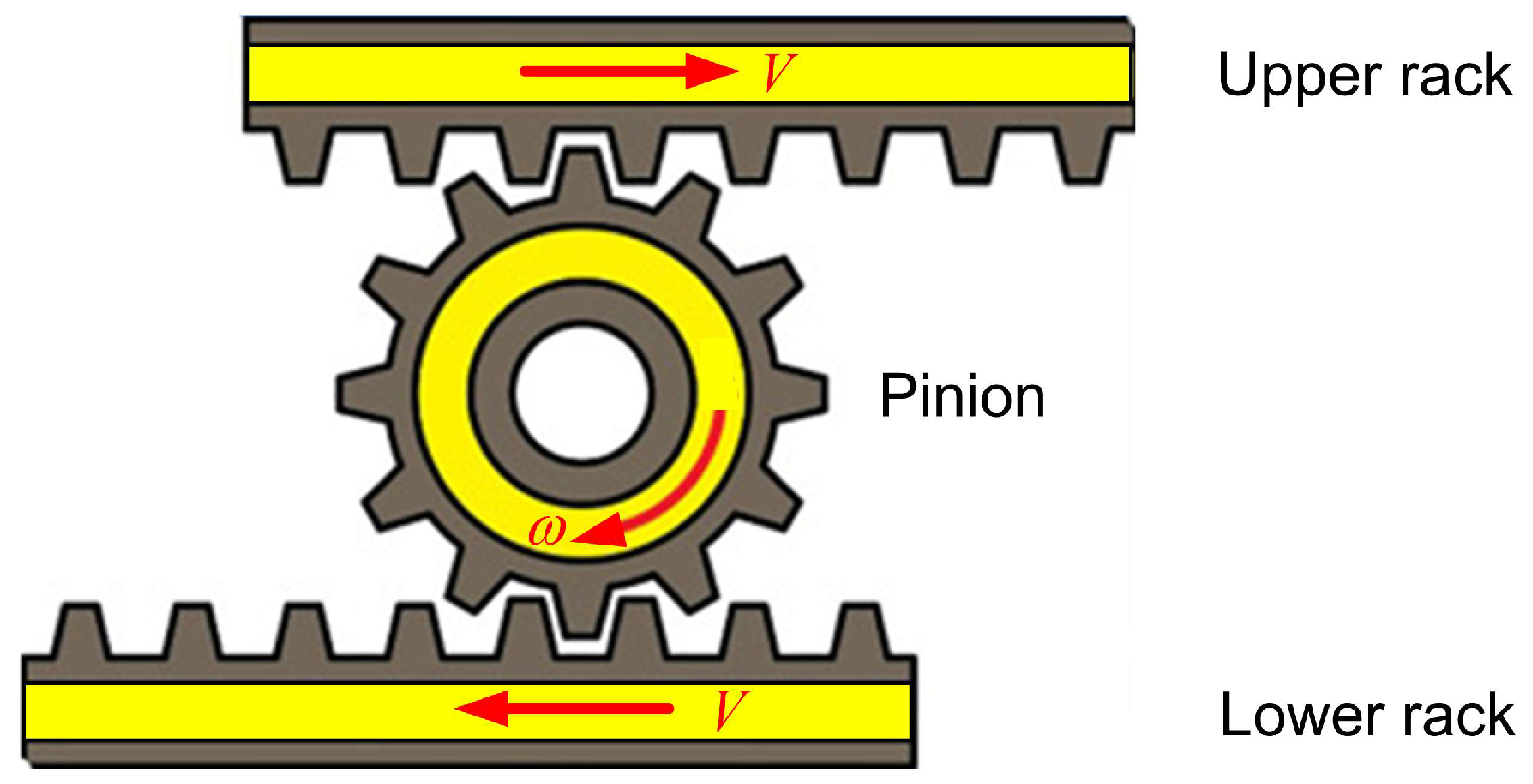
Power transmission is usually performed using gears in several configurations, one of which concerns two racks and a pinion. When the two racks are equally displaced so that the upper rack moves to the right (by distance at velocity ) and the lower rack to the left (by distance at velocity ), the pinion rotates in the clockwise direction while its center remains at rest (as shown in Figure 1). Regarding the induced normal and shear (friction) forces at the contact points between the teeth in the pinion and the racks, the well-known sliding velocity appears on the teeth surface (see [4,24]).
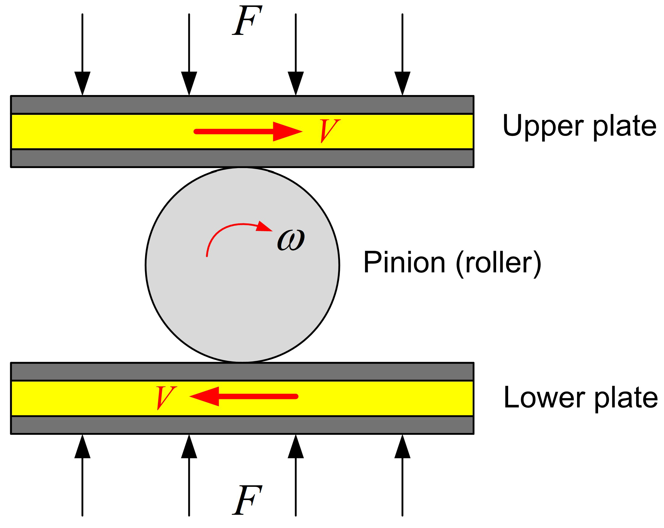
Similar kinematics could be achieved when the pinion of Figure 1 is replaced by a circular disk or a sphere which covers its pitch circle, thus becoming a roller, while the profiles of the racks become straight plates, similar to those in the usual rolling bearings [25], as shown in Figure 2. However, then we need to impose sufficient normal pressure (i.e., a set of distributed forces, ) to allow for the development of proper friction forces (, where is the friction coefficient) to transmit the available power through the contact points between the roller and the plates. The kinematics of a very similar case with a set of two identical spheres in rolling contact with two planes (so-called ‘cage-plane motion’) has been studied by Freudenstein and Soylemez [26].
3. Theoretical Study of Profiled Cams in Power Transmission
Now, the question is whether there is a standard shape to replace the plates in Figure 2, which ensures rolling contact, and thus has a high fatigue life, and does not require pre-compression by the illustrated distributed forces .
The general problem of the kinematic synthesis of conjugate profiles has been treated extensively (e.g., [27,28,29,30] and papers therein). Applications are restricted to overrunning clutches [31], gearless reducers [32] and small gear-boxes [33]. Older patents discuss asymmetric [18,19,20] or symmetric [21,22] gearless differentials using curved cam track disks (in the place of the aforementioned plates). Mostly, the sinusoidal shape has been studied [34]. Moreover, undulating face gears, which combine wavy tracks with geared surfaces, appeared a few years ago [35].
In this paper, the central issue is how to replace the abovementioned straight and conical plates with profiled ones; thus, the force shown in Figure 2 is no longer needed.
It will be shown that two circular cams in conjunction with a circular roller, as schematically shown in Figure 3, provide a working solution. After the forthcoming definitions, a new theorem of kinematics will be formulated and its proof will be derived. We start with an elementary proof based on Euclidian geometry and kinematics, and then we apply the concept of fixed and moving centrodes (polodes or polhodes) [36,37].
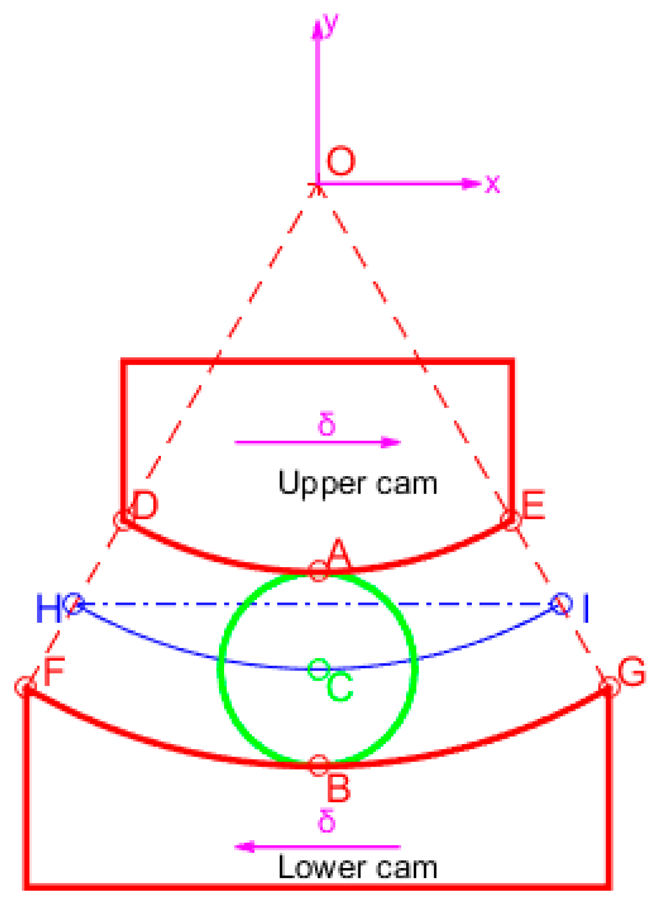
Definition 1.
Following Figure 3, let us consider two concentric circular cam tracks ( and ) of the same central angle (, in degrees), which initially have the same vertical bisecting line . Based on the mean radius , the radius of the upper cam will be , while the radius of the lower cam will be . Clearly, the gap between these two cam track disks is covered by a circular roller of center and radius , which has the freedom to move along the vertical bisecting line () toward the -direction and to rotate about its oscillating center. Technical solutions will be discussed in Section 5. Starting from this configuration, when the upper cam track is forced to translate horizontally at a velocity to the right, we consider that the lower cam track will translate horizontally at a velocity to the left. After a certain amount of time , the aforementioned opposite velocity components () will lead to equal and opposite horizontal cam displacements , as shown in Figure 3.
One may observe that, in the initial position of the cams shown in Figure 3, the contact points are () and the corresponding tangent lines between the roller and the cams are horizontal lines. Later, we shall see that there is always a specific relationship between these two tangent lines.
Theorem 1.
Given two cam tracks and a roller, according to the above definitions, for corresponding horizontal displacements where perpendicularly to the bisecting line of the common central angle (as illustrated in Figure 3, Figure 4 and Figure 5), we shall show that:
- The center of mass of the roller (point ) moves along the vertical guide () in such a way that rolling contact appears at two points which, after the displacement , occur (, ) between the roller and the two meshed cam tracks, as shown in Figure 4 (for the sake of clear visualization, point is shown later in Figure 5). Obviously, the points ( and of Figure 4) belong to the upper and lower cams, respectively.
- The slopes () of the two tangents at the abovementioned contact points (, ) are equal in measure and opposite in sign (i.e., , and ).
- The abovementioned two contact points (, ) are always symmetric with respect to the variable horizontal line passing through the center of the roller.
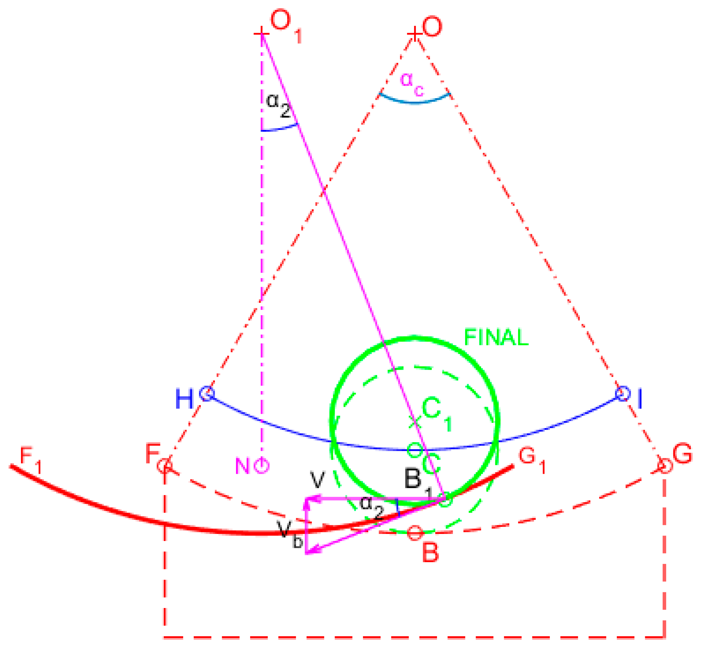
- In Figure 3, the initial position of the contact points () is the middle of the arcs and . After the displacement , the new contact points will be , as shown in Figure 4 and Figure 5, and form the angles: and . The points split the arcs in the same ratio measured from the displaced ends and ; that is, . Always, we have .
- Points ( and ) constitute the first, whereas the extreme points ( and ) shown in Figure 3 constitute the last contact pair in the mesh between the two cams and the roller.
Figure 3.
Cam tracks and a following roller.

Proof of Theorem 1.
![Eng 04 00132 g004]()
![Eng 04 00132 g005]()
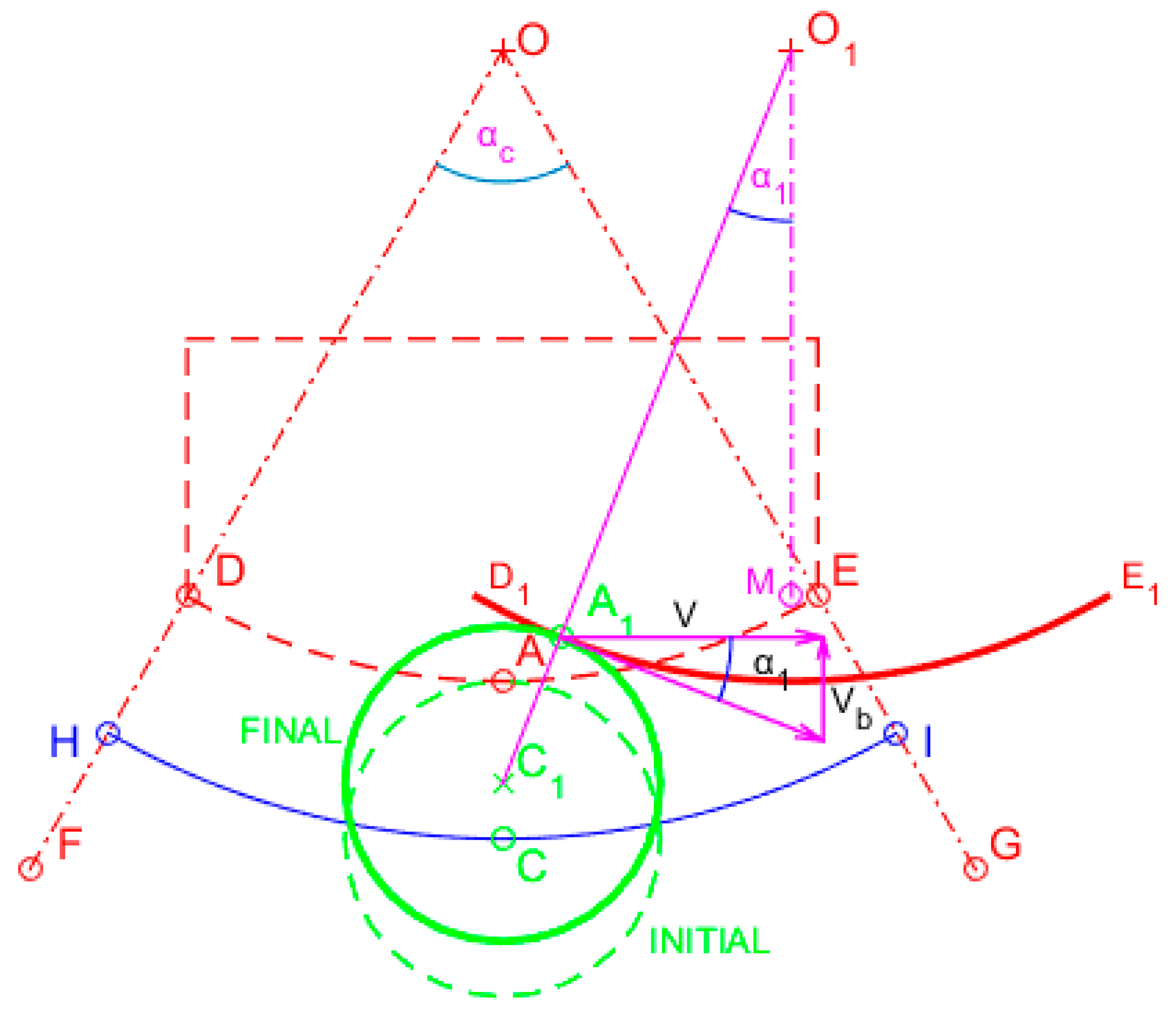
First, let us assume that the rotating axis of the roller (perpendicular to the plane of the image shown in Figure 3) is pushed from the bottom to the top by a spring; thus, when the upper cam track translates horizontally to the right at a velocity (so the curve is displaced to by , and the center moves similarly, from to , as illustrated in Figure 4), the roller will be in rolling-contact. Therefore, point will possess two velocity components, i.e., the tangential due to the instantaneous angular velocity of roller’s rotation about the center and the vertical component due to sliding along the vertical guide (), as shown in Figure 4. Since the vector sum equals , for the vertical direction, we can obtain:
with
Velocity compatibility in the horizontal direction can be denoted as , with denoting the abovementioned instantaneous angular velocity of the roller, whence:
Similarly, if we focus on the lower cam track considering a spring to push the roller downwards (Figure 5), and the curve is displaced to by to the left, the condition of rolling-contact in the vertical direction will lead to:
with
Figure 4.
Contact between the roller and the upper cam-track disk.

Figure 5.
Contact between the roller and the lower cam-track disk.

Velocity compatibility in the horizontal direction means that , whence:
Since Equations (2) and (5) share the same right-hand side, i.e., , we have . At the same time, Equations (1) and (4) provide a unique value for the vertical velocity of the roller. Finally, since , Equations (3) and (6) determine a unique angular velocity , which fulfills the conditions of rolling contact (velocity compatibility). In other words, we have shown that there is always a unique downward velocity of the center of the roller, and a unique angular velocity in the condition of rolling-contact with the two cams, i.e., the upper and the lower one. This completes the proof of part 1 and part 2 of the Theorem.
Let us now deal with the position of the two contact points of the roller, i.e., at point on the upper and point on the lower cam track disk. We recall that, generally, when two circles are in contact, their unique contact point is collinear to the two centers, i.e., it belongs to the unique line, which is determined by the two centers of the circles. This trivial theorem of Euclidian Geometry is applied twice: once for the upper cam, where we deduce
and once more for the lower cam, whence
Comparing the above Equations (7) and (8), we obtain:
Therefore, the normal projections of both contact points on the horizontal plane coincide (this completes the proof of part 3 of the Theorem), while the slopes of the tangents are equal in measure () but of the opposite sign (i.e., ).
At the displaced position shown in Figure 4, we see that the angle formed by the middle point of the straight segment , as well as the displaced center and the displaced point , equals . In other words, the circular arc corresponds to a central angle equal to . Similarly, Figure 5 shows that the circular arc corresponds to a central angle equal to . Since , we deduce that the circular arcs and correspond to equal central angles; thus, they split the total arcs to which they belong ( and , respectively) to the same ratio: . This completes the proof of part 4 of the Theorem.
Part 5 of the Theorem is a corollary of Part 4, with , and this completes the proof of the Theorem. □
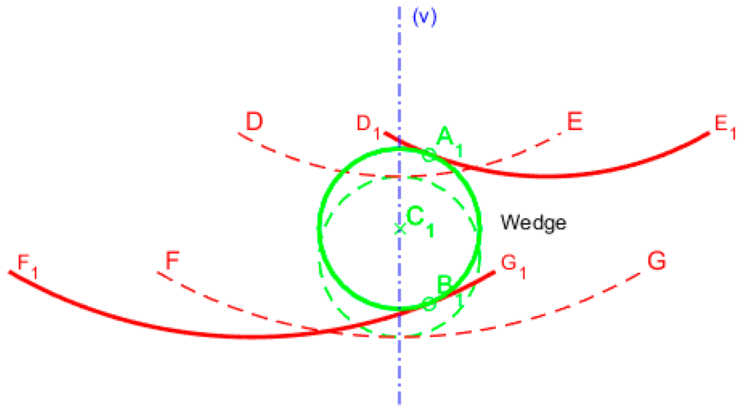
Interestingly, if we combine Figure 4 with Figure 5, then Figure 6 shows the simultaneous contacts points () which are found to the right of the vertical sliding guide (). Moreover, one may observe the wedge formed by the displaced curves and . In this situation, the initial position of the three meshed surfaces are illustrated in dashed lines, the roller (of center ) is pulled upwards in compression and rotates in the clockwise direction. Both the normal forces at () pass through the displaced center . Therefore, if power is transmitted to the vertical guide (), it further flows to the cams by rolling contact.
4. Repetition of the Initial (Reference) Circular Segment
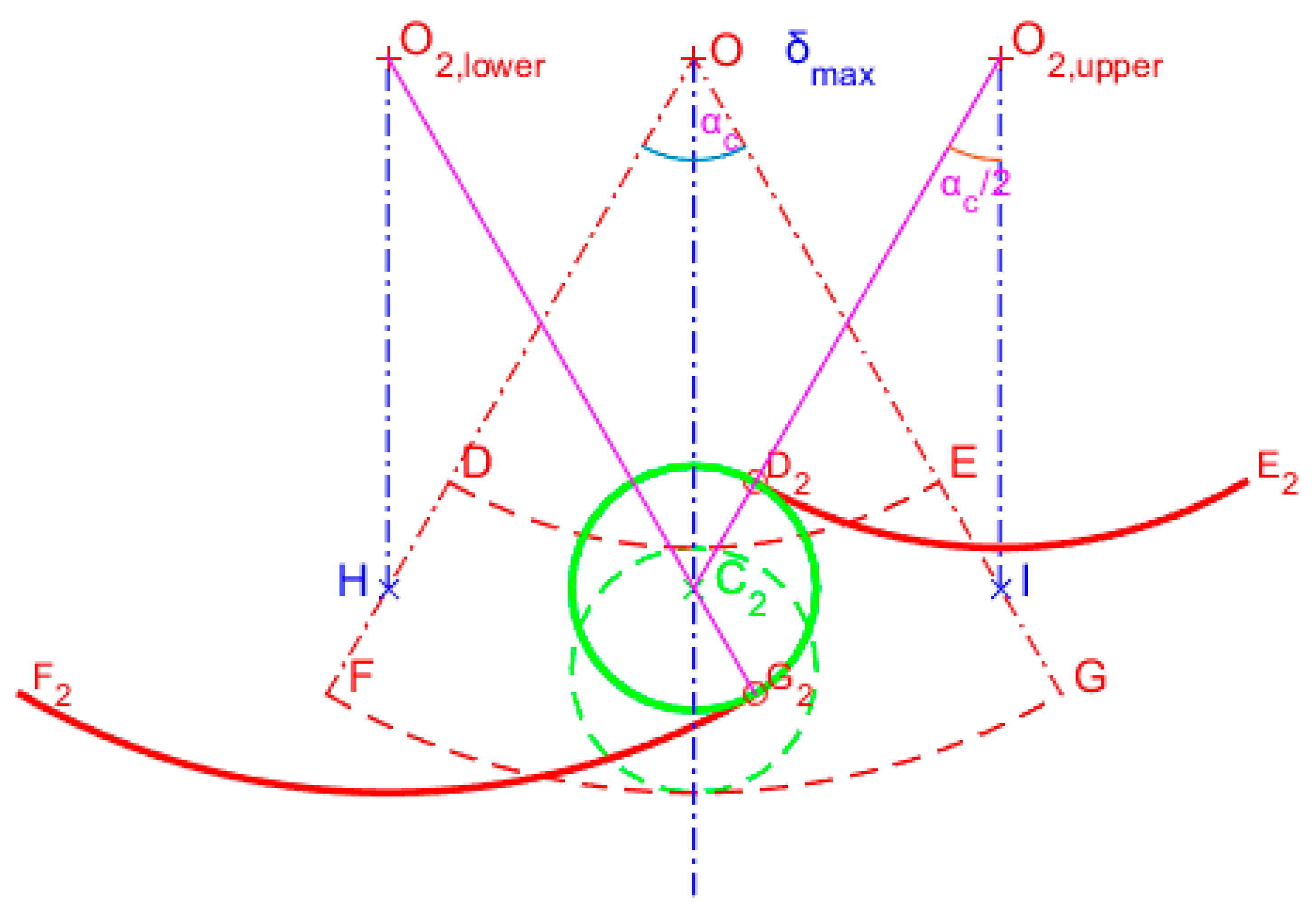
From the above Theorem 1, we recall that when the horizontal displacement of the center in the lower cam-track disk takes its maximum value, , the initial points () are then meshed at (), with the points being collinear, as shown in Figure 7.
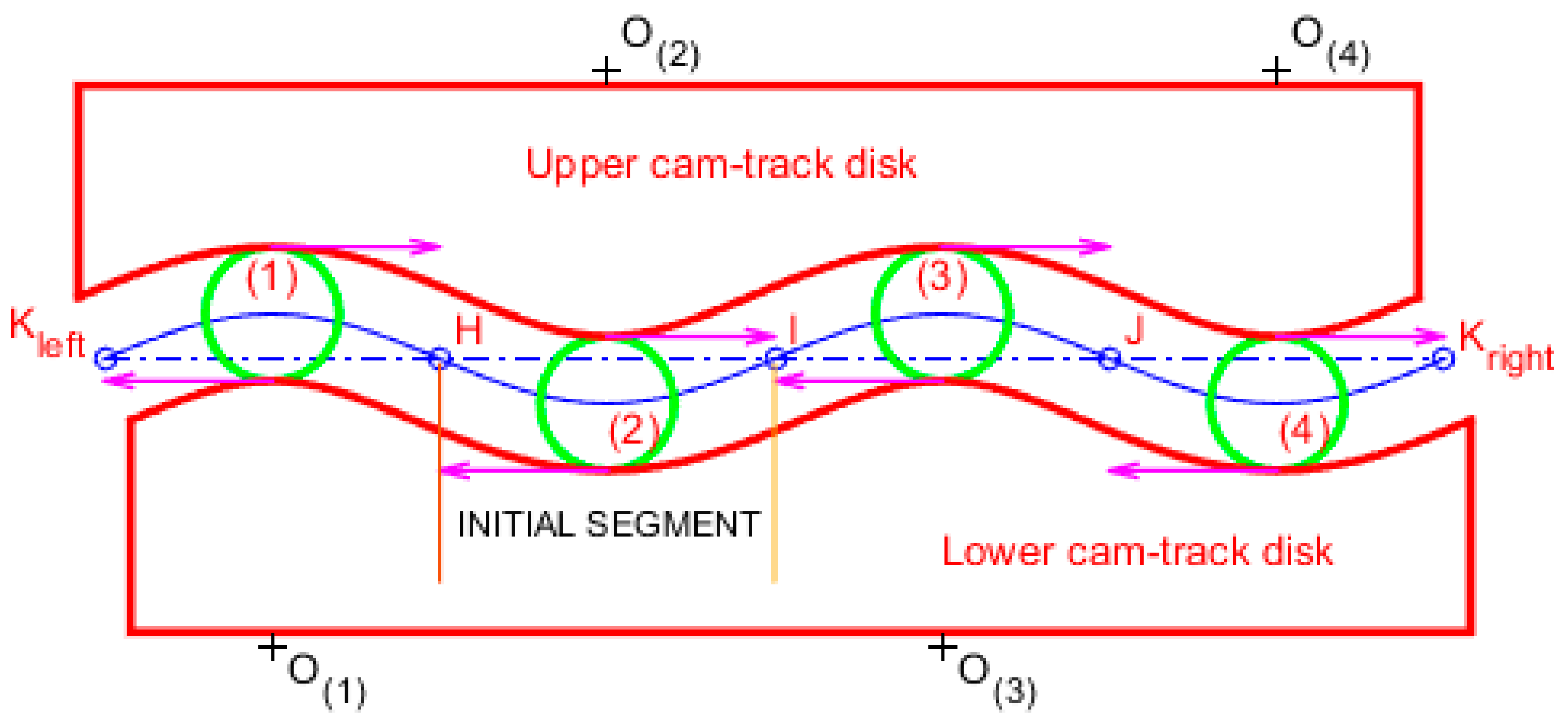
Therefore, to continue the rolling contact between the two cam surfaces and the roller, we can merely reverse the curvature of the circular arcs, as indicated in Figure 8. Note that each of the four rollers is restrained to move in the horizontal direction due to vertical grooves (guides), which do not affect the rolling-contact between the rollers and the tracks. Therefore, in this setup, the centers of mass of the rollers move only in the vertical direction.
5. Parametric Equations
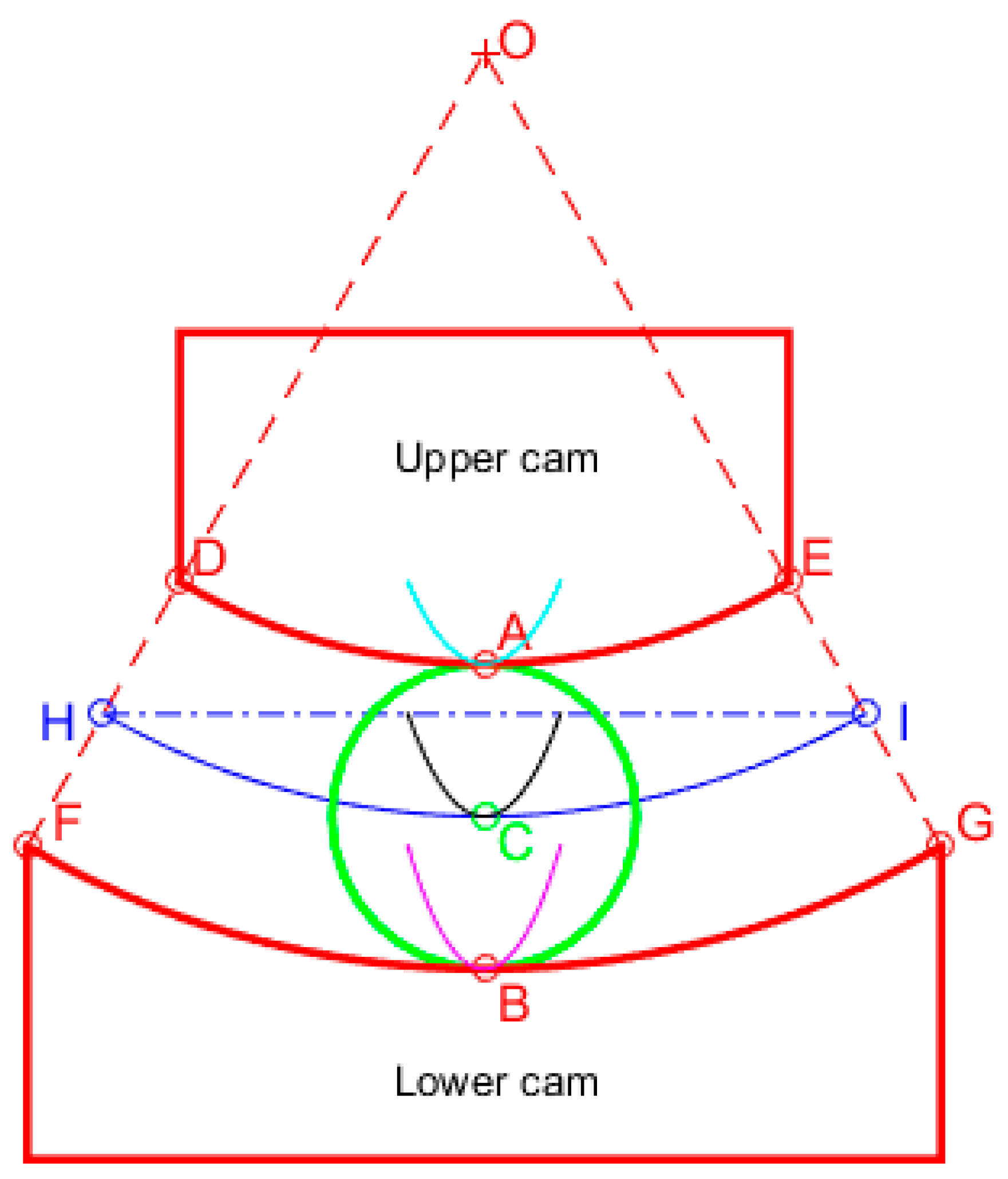
For the sake of completeness, we also present parametric equations in terms of the past time for all three bodies in motion.
We select the axis origin of the coordinate system to occur at the initial position of the center of the two circular arcs (see, Figure 3, Figure 4 and Figure 5). Starting from point (at time ) and terminating at the extreme point (with , shown in Figure 7) at time , we have the following equations for the trajectory of the center of mass of the roller, as well as for the instantaneous position of the two contact points.
5.1. Center of Mass of the Roller
By construction, the center of mass of the roller moves along a vertical slide guide, which is here assumed to be fixed in space (note that in an open differential, the sliding guide is fixed to the usually geared retainer (cage)). Therefore, by definition, the center does not move toward the -direction. As the upper cam moves to the right, it leaves space for the caged point to cover the gap moving upward. Therefore, the equations of motion of point are:
5.2. Contact Point between Upper Cam and Roller
During the time period in which the cam tracks ( and ) are meshed, the application of Equation (11) to the locus of contact point results in the cyan-colored line shown in Figure 9.
5.3. Contact Point between Lower Cam and Roller
During the time period in which the cam tracks ( and ) are meshed, the application of Equation (12) to the locus of the contact point results in the magenta-colored line shown in Figure 9.
From Equations (10)–(12), we can obtain the following relationships:
Equation (13) reflects the proposed Theorem 1, according to which the contact points have the same -coordinate, while they lie at the same distance from a line passing through the moving center of mass and are parallel to the horizontal -axis.
5.4. Locus of Instantaneous Pole (Centrode)
With respect to the fixed space system , the pole of the roller lies along a horizontal line passing through the instantaneous center of mass of the roller, and thus has the following parametric equations:
Taking the origin of the Cartesian co-ordinate system at the initial point (see Figure 3), a trivial manipulation of Equation (14) leads to
Equation (15) depicts that the locus of the instantaneous pole of the roller (centrode), for as far as the circular arcs and are meshed with the roller, moves along a part of an ellipse centered at with horizontal and vertical semi-axes equal to and , respectively. This is shown by the black-coloured curve in Figure 9, which is obviously tangent with the circular arc at initial point .
6. Implementation of the New Concept to Automotive Differentials
6.1. General Remark
The advantage of the rolling contact between the rollers and the two cams is compensated by the friction induced at the vertical sliding guides. From the other point of view, the technology required in the proposed concept is closer to the rolling bearings than the gears.
6.2. Application to Automotive Differentials
One of the possible applications of the proposed curves is the gearless differential, of which a full study, including sinusoidal curves as well as stress (finite element) and fatigue analyses, may be found in [23].
In the case of the gearless differential, the extreme points and (shown in Figure 8) are coincident, as in Figure 10. Clearly, the outer roller of Figure 10 represents the sketch element (1) of Figure 8, while the developable line becomes a whole circumference.
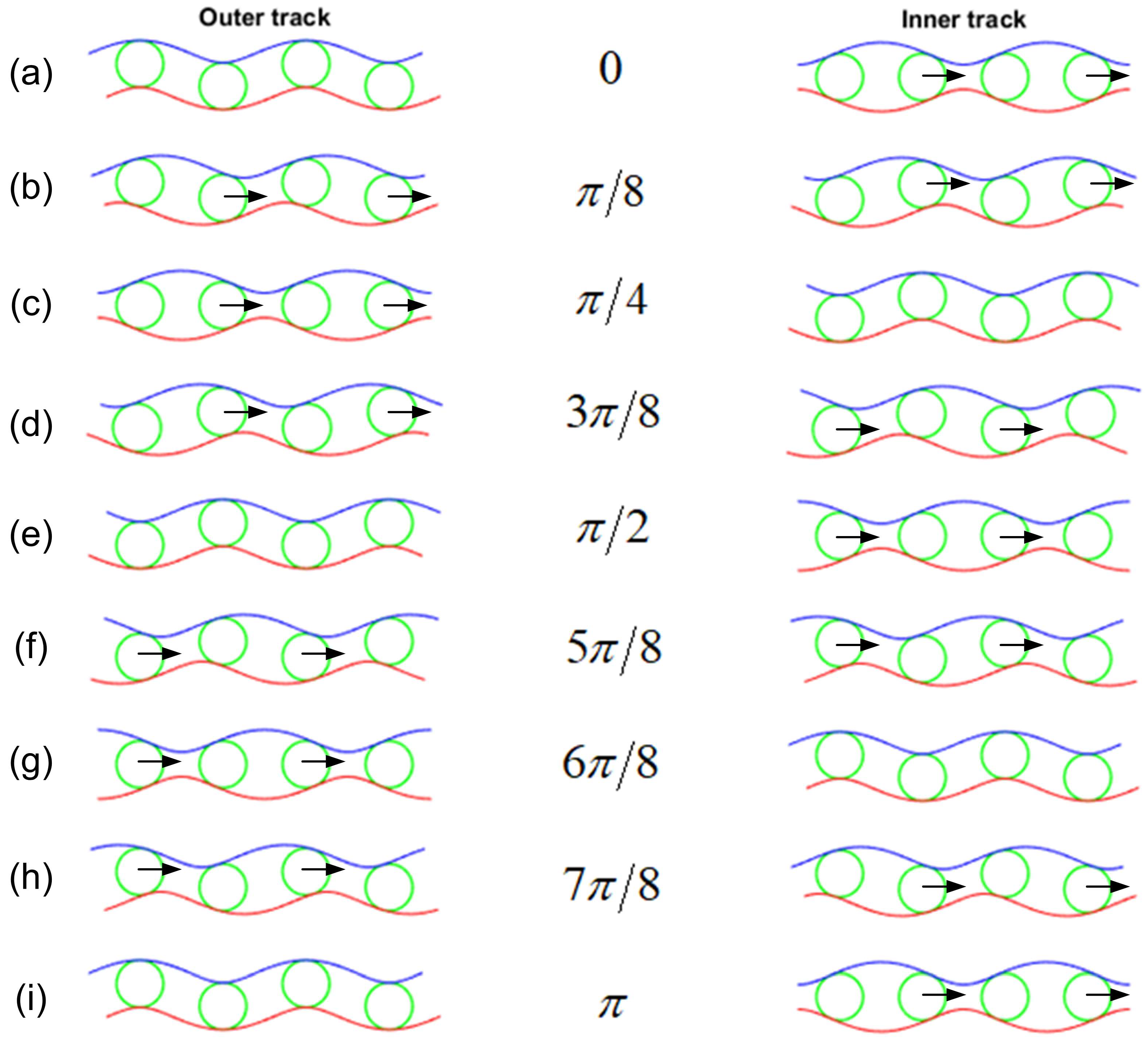
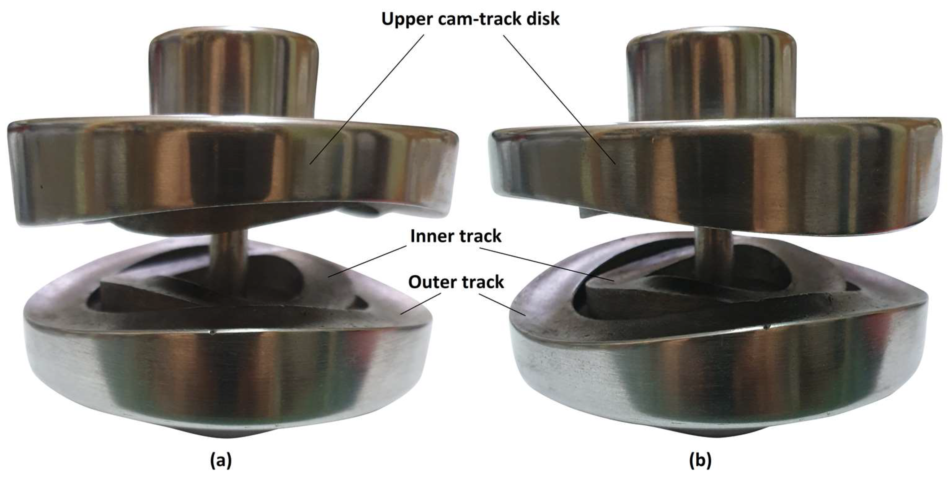
The reason for using two rollers per vertical groove is due that when all the rollers hit the top of the cam profiles, uncertainty will arise; thus, the mechanism will work intermittently. Therefore, it is necessary to install two parallel rows of rollers at the distance of one row relative to the other, as shown in Figure 11. One may observe that, between the maxima of the outer ring and the maxima of the inner ring, there is a phase-difference of exactly 45° degrees.
Clearly, the rollers are encaged in the retainer and can move on V-shaped vertical grooves by sliding (Figure 10). The rolling contact with which this paper deals refers to the contact of the two rolling members (shown in Figure 10) with the two cam-track disks (the lower one is shown in Figure 11), one upper and one lower, forming the differential mechanism. If we perform a horizontal cut in the middle, and the retainer is left out to increase our visibility, in Figure 12 we obtain the 3D shape of an entire cam-track disk, with two rows at a phase difference of 45° degrees, four vertical grooves and four pairs of rolling members (one pair per vertical groove). An almost horizontal cut of the rolling members was performed to increase our understanding of the relative motion between the rolling members and the vertical grooves.
In the design of two rows shown above, we avoid the case where all rollers are found at the extreme points (maxima and minima), thus ensuring at least one working roller per track under pressure, as illustrated in Figure 6. It is also worth mentioning that both cam-track disks, upper and lower, are identical in shape and size. thus minimizing manufacturing and storage costs.
The advantage of the proposed circular cams is the supposed self-regulation of the differential device to variable road conditions without additional means (i.e., those used in locking and limited slip ones). Note that if the central angle is relatively small with respect to the coefficient of friction between the outer support of the cam-track disks in the housing (for design details, see [21]), i.e., when , the wedge shown in Figure 6 obeys the rule of the inclined plane, a self-blocking performance has been noticed [23]. In other words, the entire mechanism operates as an equivalent one-dimensional inclined plane in the circumferential direction.
The upper cam-track disk of the abovementioned graphs is actually connected to the (say) left driving wheel of the automobile vehicle. Similarly, the lower cam-track disk is connected to the right driving wheel.
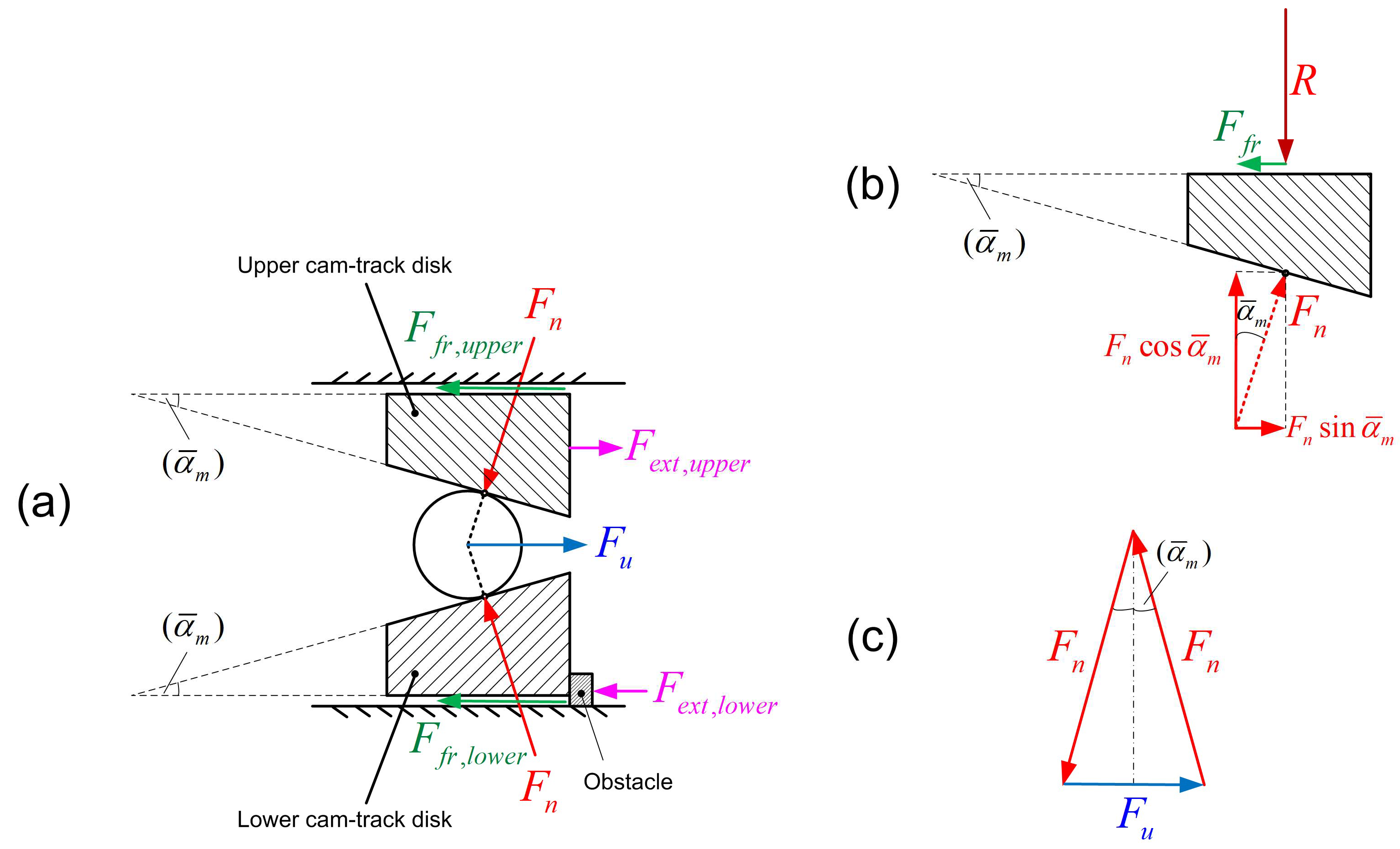
7. Force Analysis in a Simplified Model
7.1. Mechanical Model
Figure 13a represents any of the four active rollers operating between the two cam-track disks. Under certain conditions, the totality of the aforementioned four active rollers constitutes an equivalent roller. Thus, Figure 13a shows that the circumferential force , which is transmitted to the roller through the vertical grooves of the retainer, is cancelled by two contact forces ; these should be almost vertical to the inclined plane of the averaged angle (as the rolling friction is very small). Of course, the frictional force along the vertical groove at which the rollers slide changes the situation; thus, the normal forces are not exactly equal to one another. Again, the truth is that the circumferential force is cancelled by the sum of the two normal forces plus the unknown frictional force, a matter which will be discussed later.
Below we present an elementary mechanical analysis for the determination of forces and contact pressures.
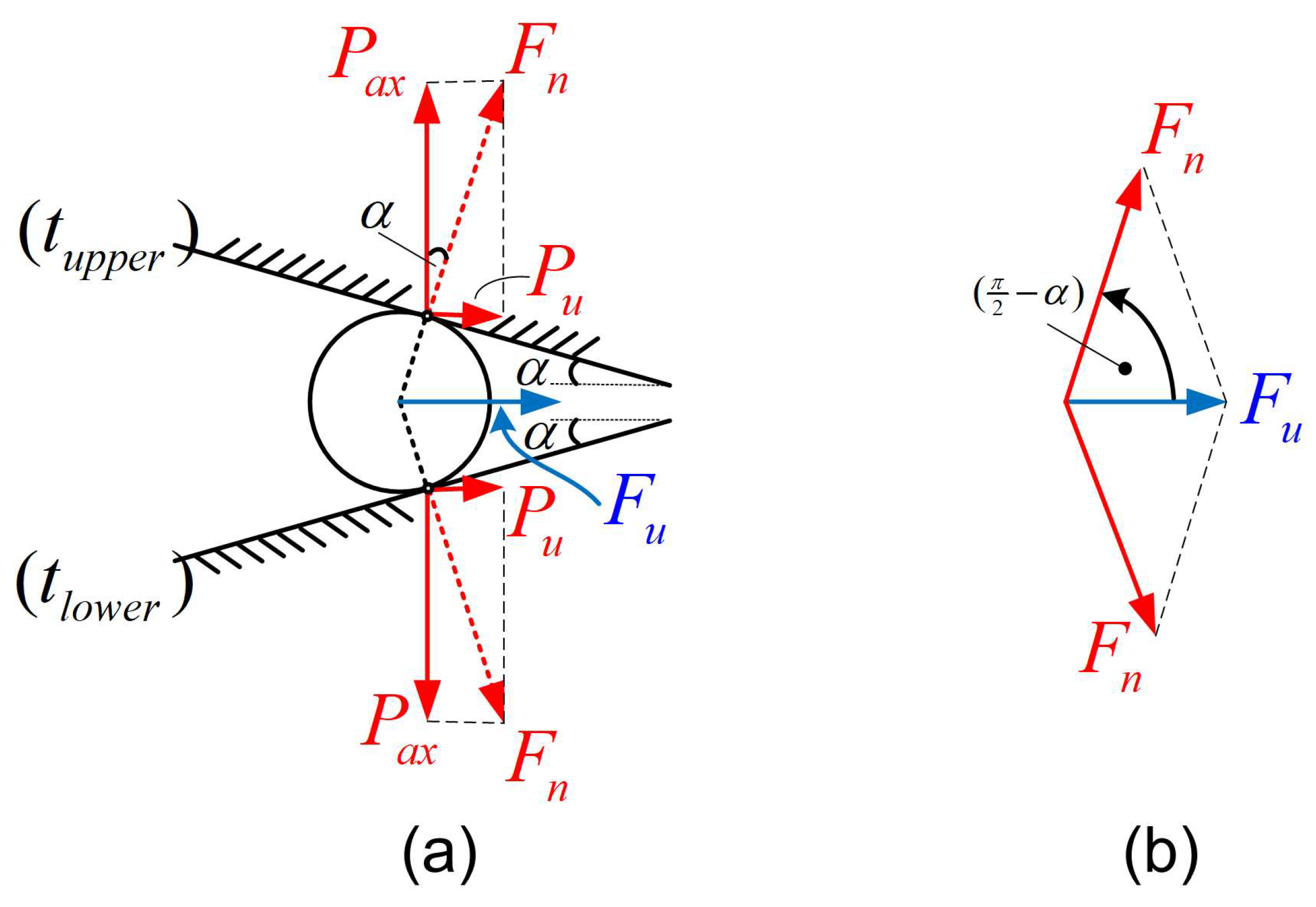
In an automotive differential, the engine power is transmitted from the geared crown to the attached retainer (cage), and then through V-shaped supporting grooves to the rollers. Thus, circumferential forces, and are induced in the outer and the inner tracks, respectively. The identification of the working elements is as follows. Only those elements of which the horizontal components of the outward unit vector are directed toward the circumferential velocity of the crown (as shown in Figure 14) are actually working and transmitting power. As previously mentioned, this occurs for only half of them in each track (i.e., two in the outer track and another two in the inner track), which can be easily identified in Figure 15, as denoted by arrows .
In each track, the serial numbering of the rollers ranges from 1 to 4, as shown in Figure 8. Rollers in contact but in different tracks have the same serial number. Since, at each time instance, only half of the rollers push each track, either No. (1,3) or No. (2,4), at a phase difference of 180 degrees (in anti-diametrical positions), we can safely consider that the exerted moment in the outer track is due to one pair of forces (for example, those exerted on No. (1,3), shown in Figure 15f–i), thus forming a moment of force couple . Similarly, another pair of forces in the inner track with a corresponding moment of force couple is exerted in the inner track. Therefore, the total moment , which is transmitted from the geared crown to the cage of the differential device, will be:
Assuming that the friction between the rollers and the cam tracks is negligible (rolling-contact), and also neglecting the friction at the V-shaped grooves, each of the above circumferential forces is analyzed into two equal force components of equal size, both normal to the surface of the surrounding tracks. Then, each of the forces is further analyzed into one axial to the cam-track disk and another circumferential/radial component () according to Figure 16a.
Ignoring the dynamic effect as well as the significant frictional force at the V-shaped grooves, the static equilibrium of the roller overestimates the force components as follows:
and
Although the system is not statically determined (redundant) and the relationship between and is a matter of elasticity, to obtain a closed-form analytical solution we further assume rigid-body conditions; thus, the circumferential forces are proportional to their distance from the center:
Then, solving in from Equation (19), and substituting into Equation (16), we obtain:
It should become clear that only half of the moment given by Equation (20) is transmitted to each cam-track disk. Since each cam-track disk undertakes the moment:
the total transmitted moment will be:
By virtue of Equation (20), Equation (22) becomes:
Therefore, if the transmitted moment is known, the circumferential force in the outer track is given by:
Combining Equation (19) with Equation (24), we can obtain the circumferential force in the inner track:
7.2. Normal Forces
Based on the above circumferential forces, and , we can calculate the normal forces in both tracks.
Therefore, the normal force in the outer track is given by:
Also, the normal force in the inner track is given by:
Each active spherical roller presses, by the normal force (either or ), the corresponding track, which has two curvatures in space. According to the generalized Hertz theory, which refers to the contact of two ellipsoidal surfaces [38], at the contact point of each track, the equivalent curvatures in the two perpendicular - and -directions are given by:
and the radius of an equivalent sphere is:
Based on the normal contact force and the abovementioned equivalent radius , the maximum contact pressure becomes:
In Equation (30), refers to either (), to either (), while the equivalent elastic modulus is determined by:
where and are the elastic moduli and the Poisson’s ratios of the rollers and the tracks, respectively.
7.3. Axial Forces
The abovementioned moment is equally transmitted from the rolling members to both the cam-track disks by the two working normal forces and (the same per track for each cam-track disk, directed to the wheels) of total magnitude
The above sum includes two equal forces per track (which shows the involved factor “2” in Equation (32)) and is cancelled by the friction on the friction disk.
It should become clear that only half of the moment given by Equation (23) is transmitted to each cam-track disk. Actually, each cam-track disk undertakes the moment given by Equation (21).
Combining Equations (22) and (23), we have:
Since the friction should not exceed the maximum static value, we may set a desired threshold for the maximum moment at each cam for which full blocking is ensured; thus, we can write:
where is the coefficient of friction and is the equivalent diameter of friction. From standard machine elements and design books, we know that the latter variable depends on the assumptions imposed in clutch theory, either uniform-pressure or uniform-wear conditions. Following the uniform-pressure condition, we have (see, [39,40]):
where and is the outer and the inner diameters of the friction disk, respectively.
Substituting Equation (17) to Equation (19) into Equation (32), we can see that each cam-track disk undertakes the total axial force:
Then, substituting Equations (33) and (36) into Equation (34), after a reduction in the common factor , we obtain:
In order to make further analysis easy, we assume that the angles are small and that similarity conditions between the outer and inner track are assumed; thus, according to [23], the sum of the two contact angles is constant:
where
Under these circumstances, the function at the left part of Equation (37) may be approximated in terms of only , as follows:
Since the right-hand side of Equation (37) is a constant, we are seeking a condition that will ensure that this equation will be valid even for the minimum value of the left-hand side. Actually, the function may obtain close-to-infinite values when ; thus, Equation (37) will be fulfilled for small values of (where ), but it is easy to see that it also possesses a minimum value. Equating the first derivative of to zero, the only acceptable solution for the optimality condition (less than ) is:
Thus, for the particular value of the outer contact angle given by Equation (41) and the associated inner contact angle given by Equation (38), i.e., , Equation (37) finally implies the following critical threshold:
In conclusion, Equation (30) is the most important formula regarding the maximum induced stress between the rollers and the cam-track disks, while Equation (42) is a good estimation of the maximum inclination angle, which equals half the central angle of the meshed circular arcs.
8. Results
The results concern (a) experiments and (b), with manual calculations based on previous sections.
8.1. Experiments
Using a prototype that was manufactured according to [21], two simple experiments were conducted as follows:
Bench experiment No.1: We put the right shaft (i.e., the extension of the lower cam-track disk) into a mechanical clamp, while the other shaft (extension of the upper cam-track disk) is left free. Then, a torque is progressively exerted on the retainer (between the two shafts). It was observed that the rotation of the retainer is impossible even if a very high torque is applied. Nevertheless, by applying even a small torque to the left shaft, the latter can easily rotate twice as fast as the retainer.
Bench experiment No.2: We carefully put the retainer into a mechanical clamp. We observe that it is impossible to turn only one shaft, regardless of the magnitude of the applied torque. If, however, a small torque is applied to the other shaft in the opposite direction, then both shafts rotate (in opposite directions) at the same angular velocity.
The above two experiments are very enlightening and support the theory of the previous Section 7.3.
8.2. Rough Estimation of the Inclination
According to Table 1, the following data were adopted.
Diameters of cam-track disks: , .
Rolling members: , .
Friction disks: , and .
Substituting the above figures in Equation (35), the equivalent diameter in the friction disks is estimated as:
We assume that the force-to-force and diameter-to-diameter ratios are equal to each other, as in the pivoted connections; thus, Equation (19) implies:
Substituting the above numerical values of Equations (43) and (44) into Equation (42), we obtain:
Therefore, using the numerical result given by Equation (45), for similar tracks, the maximum allowable central angle will be twice the value shown by Equation (45); thus, its upper limit will be:
8.3. Calculated Stresses
The basic parameters of the model were obtained according to Table 1. The stresses were calculated according to Equation (30), in which the normal force depends only on the standard inclination angles of the two tracks and the standard input torque (all found in Table 1). In contrast, the radius of the equivalent sphere in the denominator of Equation (30) is a very crucial design parameter, which (by virtue of Equation (28)) highly depends on the double curvature of each track.
Based on the above data, in conjunction with a typical input torque applied to the crown attached on the cage, for the above inclination angle we apply Equations (26) and (27) to derive the normal forces on the outer () and the inner track (), respectively.
Furthermore, regarding the derivation of a large value for , after many trials, which all resulted in high stress values, acceptable stresses were obtained for at least the following design details (these reference values are close to those of the prototype, for which a finite element analysis has been documented in [23]):
The substitution of Equation (47) into Equations (28)–(30) leads to contact pressures equal to 1.6 MPa and 1.2 GPa for the outer and the inner track, respectively.
It is worth mentioning that, as also shown in Table 2, an accurate three-dimensional finite element analysis (FEA) for the same dimensional parameters and input torque resulted in smaller values, i.e., 1.3 GPa and 0.8 GPa, respectively [23]. The deviation between the above simplified mechanical model and FEA is mainly attributed to the existence of frictional forces at the V-shaped groves; thus, the assumed synthesis of forces in Figure 14b is not absolutely correct because—eventually—the friction cannot be ignored.
Despite the above differences in the two models, the simplified mechanical model was of major significance, because Equations (28)–(30) could quickly consider and elucidate the influence of the curvatures in the tracks. Clearly, for each candidate combination of detailed parameters determined by Equations (28)–(30), a corresponding FEM model has to be developed afterwards.
Note that when the design includes spherical rollers, the first two equalities of Equation (47) remain untouched because both radii of the roller are equal to the radius of the corresponding sphere. In contrast, we shall show that the induced stresses are sensitive to the chosen curvatures on each track. Between the many combinations, let us preserve the same inclination angles as previously used (according to Table 1), and then let us standardize the radius for the outer track, and the radius for the inner track. Considering Equation (30) from the simplified model of Section 7.2, Table 3 shows the effect of the chosen radii and in the outer and the inner track, respectively (note that equal factors were imposed for and ).
Another result for this sub-section refers to the sensitivity of the inclination angles. As a reference, we can consider the initial case (according to Table 1) in which the inclination angles are and , respectively. Then, by imposing a uniform change around the reference values, Equation (30) leads to the results shown in Table 4 (change of about ).
As a last note, a uniform variation of and by influences the contact stresses by less than .
8.4. Interpretation of the Experiments
The contents of Section 7.3 and the numerical results of Section 8.3 suggest that the main design philosophy of this gearless differential is concerned with an adequately small central angle , so that the averaged inclination angle fulfills the condition , where is the coefficient of friction between the outer ‘side boundary’ of the cam-track disks and the housing. The conditions of Experiment No.1 are illustrated in Figure 13a. The equilibrium of the upper cam-track disk is shown in Figure 13b, in which the normal force is analyzed into two components, which are cancelled by the frictional force and the normal reaction . According to the well-known rule of the inclined plane (for the sake of completeness, as repeated in Appendix A), for such a small angle no matter the size of the normal force , the static friction does not exceed its maximum static value; thus, no sliding occurs in this position.
Moreover, if we exert a force (in the same direction as the ) on the upper cam-track disk to overcome the side friction in the housing (see, Figure 13a), due to this net force, the horizontal motion of this part becomes possible. If the right driving wheel of a vehicle is blocked, it is possible to operate the differential mechanism even by exerting a small force on the free left driving wheel, a fact that justifies the abovementioned blocking behaviour of this mechanism.
8.5. Typical Screenshots during the Operation of the Gearless Mechanism
The initial position of the two tracks () is that shown in Figure 8. It is also repeated in Figure 15a for the outer and the inner track (parallel in the form of circumferences/rows separated by a distance). In Figure 15i one may observe that the same picture, as the top (Figure 15a), appears after half a turn of each cam-track disk (rotational angle ). In general, when the upper cam-track disk (left shaft) rotates by , the lower one (right shaft) will rotate by ; thus, their phase-difference will be . Therefore, the angle that appears in the middle column of Figure 15 refers to the aforementioned rotational angle of each cam-track disk (shaft). Obviously, within each cam-track disk (upper or lower), the outer and inner tracks (rows) rotate by the same amount as a rigid body. In more detail, from Figure 15, we can obtain the following results:
- At the angle 0°, all four rollers of the outer track hit the tops of the cam profiles (see also Figure 8), while those of the inner track do not.
- At the angle 45°, all four rollers of the inner track hit the tops of the cam profiles, while those of the outer track do not.
- At the angle 90°, all four rollers of the outer track hit the tops of the cam profiles, while those of the inner track do not.
- At the angle 135°, all four rollers of the inner track hit the tops of the cam profiles, while those of the outer track do not.
- At the angle 180°, all four rollers of the outer track hit the tops of the cam profiles (see also Figure 8), while those of the inner track do not.
From the above discussion, it is clear that every half a turn of each shaft (), we take exactly the same picture of the eight rollers. This happens because, by construction (according to Figure 8), we can obtain two complete periods .
Furthermore, in Figure 15b, which corresponds to (i.e., each shaft has performed of a full revolution), one may observe that two rollers in the outer track and another two in the inner track press the profiled cams (in the direction of the arrows), thus transmitting power. Interestingly, as the outer track rotates by it sweeps an angle equal to ¼ of the central angle , and at the same time the inner track rotates in the same direction by the same amount (), now sweeping an angle equal to ¼ of the central angle .
Concentrating on Figure 15, one may observe that, at four out of the eight rollers, depicted by arrows , transmit power:
- Two out of the four rollers in the outer tracks are active, pushing them in the circumferential direction (thus transferring part of the power).
- Two out of the four rollers in the inner tracks are active, pushing them in the circumferential direction (thus transferring the rest part of the power).
In contrast, in the remaining five cases only two rollers are active. In other words, there at least two rollers are engaged in a wedge formed at the contact points with the cam-tracks.
9. Discussion
9.1. Other Patents on Gearless Differentials
Clearly, although repeated (sinusoidal like) curves have been used for many years [18,19,20,21,22], to date, the property of fully rolling contact cam track surfaces has neither been revealed nor studied. Readers who have experience in evaluating patents may refer to the originals [18,19,20] and could find the following comments to be useful:
In Beucher’s patent Nr. 741,812 (granted in 1943) [18], there is an outer and an inner groove. In each groove, the curves of the cam-track disks are repeated cylindrical arcs of interrupted shape with sharp edges; thus, high-contact stresses are induced and fatigue phenomena are anticipated. There is substantial sliding between the sliding plate-like elements (in pairs) and the cam track disks. This mechanism works as a clutch, with the result of a low coefficient of efficiency. The wear is high due to friction and high temperature, and thus its operation is very problematic. Power transmission is circumferential. The shape of driving elements is different than that proposed (rectangular with smooth sliding surfaces). The inventor himself states that his invention is for the back shaft only.
In Randall’s patent No. 2,651,214 (applied in 1950, granted in 1953) [19], there is again an outer and an inner groove. The curves of cam-track disks have sharp edges; thus, high-stress concentration is anticipated. Power transmission is circumferential. During differentialization, high friction and a high temperature develop, which wears rolling members at points that then rolls them on the driven cam-track disks, leading to the destruction of rolling. Rolling members have a frusto-conical shape. This works as a clutch.
In Altmann’s patent No. 2,967,438 (filled in 1958, granted in 1961) [20], there is only one groove, in contrast to the abovementioned patents [18,19]. The curves in cam-track disks are sinusoids, but this fact does not result in the full rolling of driving elements without sliding. In more detail, the curves are unsymmetrical with each other (one cam track has 5 maxima and 5 minima, whereas the other has 6 maxima and 6 minima), thus leading to unequal inclination angles. The asymmetry between two driven cam-track disks results in unequal action on the wheels. Equalizing means are provided at both driven sides.
9.2. Overall Advantages of the Proposed Concept
From the above discussion in around Figure 13, it becomes obvious that the proposed concept is against the operation of the open differential. Clearly, experiments reveal that when one of the drive wheels meets mud or snow, even a minor resistance to the other drive wheel offers motion. However, this is not a limited slip differential in the classical sense, since no additional means exist, except for two bronze disks in the outer part of the cam-track disks (for construction details, see [21,22]). Clearly, the particular shape of the cam tracks, which leads to an interchangeable shape for both of them, can be efficiently manufactured through CNC machining centers, thus reducing overall costs. This shape ensures rolling contact and a kind of ‘self-regulation’, meaning that the power transmission obtained through this differential is somehow adjusted to road conditions.
In the particular case of helicopters in which the gearbox suffers from possible fractured gear teeth, it is obvious that the adoption of the proposed concept, in conjunction with a small inclination angle α, would not lead to full destruction because the small angle and the associated static friction (inclination rule) would prevent this.
9.3. Design Aspects of the Present Concept
In contrast to the above relevant patents [18,19,20], the use of the proposed circular curves (indicated in Figure 3) allows for the transmission of power through a radial arrangement of the rolling members. The support of the rolling members is achieved by sliding grooves (guides) into the retainer, but this does not affect the rolling contact between them and the cam-track disks. Rolling members are either in couples or independent. Rolling members are drum-shaped (spherical, conical, etc.), i.e., of an axisymmetric form. The same concept works with any even number on each curve: 2, 4, 6, 8, and so on. Then, the total number of rolling members is 4, 8, 12, 16, or any other multiple of 4. Rolling members are arranged in two concentric circumferences (one outer and one inner). The particular case of rollers per circumference is shown in Figure 16: (a) for the initial state of parallel tracks and (b) after a rotation of the upper cam-track disk by 90° degrees in the counter-clockwise direction. Note that when the outer curves are parallel (Figure 16a), the inner ones form the maximum wedge angle. In contrast, when the outer curves form the maximum wedge angle (Figure 16b), the inner ones become parallel. In addition, details of the prototype at a regular size, including the rollers as well as stress and fatigue analysis, may also be found in [23]. Although this has been previously noted, it is instructive to repeat that, in cases where the prototype of Figure 16 is used as a gearless automotive differential, the upper cam-track disk is firmly linked to the left half-shaft of the drive wheel, while the lower one is linked to the right half-shaft.
By neglecting the friction at the V-shaped grooves, in the simplified model of Section 7.2, we used Equation (17) to determine the total axial force Pax directed toward the half-shafts and pressed the friction disk on the housing of the gearbox. For a given coefficient of friction , the obvious condition is that the maximum torque transmitted between a friction disk and the housing of the gearbox should not exceed the value imposed by the maximum static friction. This inequality was used to analytically determine the maximum allowable average inclination angle for the whole mechanism. This model somehow suffers due to the hard assumption of frictionless operation at the V-shaped grooves. Of course, since the relative velocities are analytically known everywhere in the power-train, one could introduce an assumption for the friction (e.g., ), but this issue is beyond the scope of this paper.
9.4. Other Applications
Although the motivation for developing the concept of the two conjugate wavy cam-track disks was primarily the differential gear (useful for tractors as well as for military and passenger vehicles), the theory covers a lot of other power transmission applications in mechanical engineering. For example, the same concept could be applied to replace gearboxes in several drives, such as wind-turbines, mills, conveyors, mixers, pitch controls in aeronautical engineering, high-safety transmissions for helicopters, multi-step marine-type gearboxes, robotic devices such as pitch–roll wrists, electric cars, etc.
The wavy form of the cam tracks may also be useful for other applications where controlled oscillations are needed, such as the replacement of the camshaft (obvious) and/or the crankshaft (giving it a circular shape) in (single- or double-stroke) internal combustion engines, as well as for piston pumps and compressors, among others.
As a last note, if we wish to categorize the proposed new concept, it might be considered a practical contribution to power transmission through kinematic contact (in German, Formschluss [41]).
10. Conclusions
The findings of this paper suggest that:
- (1)
- Ideal (pure) rolling (without sliding) of a roller on the two surfaces of cams (profiled plates) is achieved when the center of mass of the roller moves along a circular arc bounded by a given central angle.
- (2)
- If this design concept is applied to an automotive differential for an even number of repetitions, it leads to two identical cam-track disks (i.e., symmetrical differential), thereby saving manufacturing and storage costs.
- (3)
- If the central angle is small, self-regulation and blocking are achieved through the principle of the inclined plane.
- (4)
- The proper selection of particular dimensional parameters, such as double curvature, leads to mechanical stresses, which are within the usual allowable limits.
- (5)
- A weakness of this study is that elastic deformation of the cam-track disks has not been considered.
Funding
This research received no external funding.
Institutional Review Board Statement
Not applicable.
Informed Consent Statement
Not applicable.
Data Availability Statement
Upon request.
Conflicts of Interest
The author declares no conflict of interest.
Nomenclature
| Quantity | Explanation |
| Diameter and radius of cam-track disks (outer and inner). | |
| Diameter ratio . | |
| Radius of rollers (outer and inner track). | |
| Diameters of friction disks (outer and inner). | |
| Equivalent diameter of frictions disks (with uniform pressure). | |
| Coefficient of friction on friction disks. | |
| Central angle (outer and inner track). | |
| Contact angle (outer and inner track). | |
| Torque transmitted from the geared crown to the totality of two cam-track disks. | |
| Torque transmitted to each cam-track disk. | |
| Circumferential force at each active roller (outer and inner track). | |
| Normal force on cam-track disk transmitted by active roller (outer and inner track). | |
| Circumferential force on cam-track disk transmitted by active roller (outer and inner track). | |
| Axial force on cam-track disk transmitted by active roller (outer and inner track). |
Appendix A
We consider a particular groove (external or internal). The corresponding reaction force (see Figure 13b) cancels the horizontal projection of the normal force thus,
Also, the friction cancels the vertical component of force ; thus,
Dividing (A1) and (A2) by parts, we receive:
Considering that no sliding occurs, the static friction is smaller than the maximum one:
From (A3) and (A4), one can obtain the well-known inequality:
In other words, when the inclination angle of a cam surface is smaller than a critical limit, there is no sliding between the planar surface of the corresponding cam-track disk and the surrounding housing (for a possible practical implementation, see [18]); thus, it works as a ‘blocking’ differential mechanism. Otherwise, if , it works as a usual differential mechanism.
References
- Bahk, C.-J.; Parker, R.G. Analytical investigation of tooth profile modification effects on planetary gear dynamics. Mech. Mach. Theory 2013, 70, 298–319. [Google Scholar] [CrossRef]
- Huai, C.; Zhao, Y. Meshing theory and tooth profile geometry of toroidal surface enveloping conical worm drive. Mech. Mach. Theory 2019, 134, 476–498. [Google Scholar] [CrossRef]
- Ghosh, S.S.; Chakraborty, G. On optimal tooth profile modification for reduction of vibration and noise in spur gear pairs. Mech. Mach. Theory 2016, 105, 145–163. [Google Scholar] [CrossRef]
- Litvin, F.L.; Fuentes, A. Gear Geometry and Applied Theory, 2nd ed.; Cambridge University Press: Cambridge, UK, 2004. [Google Scholar]
- Sakaridis, E.; Spitas, V.; Spitas, C. Non-linear modeling of gear drive dynamics incorporating intermittent tooth contact analysis and tooth eigenvibrations. Mech. Mach. Theory 2019, 136, 307–333. [Google Scholar] [CrossRef]
- Liang, X.; Zuo, M.J.; Feng, Z. Dynamic modeling of gearbox faults: A review. Mech. Syst. Signal Process. 2018, 98, 852–876. [Google Scholar] [CrossRef]
- Mihailidis, A.; Nerantzis, I. Recent Developments in Automotive Differential Design. In Power Transmissions, Mechanisms and Machine Science; Dobre, G., Ed.; Springer Science + Business Media: Dordrecht, The Netherlands, 2013; Volume 13, pp. 125–140. [Google Scholar] [CrossRef]
- Bai, S.; Angeles, J. The design of spherical multilobe-cam mechanisms. Proc. Inst. Mech. Eng. Part C J. Mech. Eng. Sci. 2009, 223, 473–482. [Google Scholar] [CrossRef]
- Chaudhary, M.; Angeles, J.; Morozov, A. Design of a Spherical Cam-Roller Mechanism for an Automotive Differential. Trans. Can. Soc. Mech. Eng. 2016, 40, 243–252. [Google Scholar] [CrossRef]
- Butterfield, S.; Smith, J.; Petch, D.; Sullivan, B.; Smith, P.; Pierce, K. Advanced Gearless Drivetrain-Phase I Technical Report; National Renewable Energy Laboratory: Golden, CO, USA, 2012. [Google Scholar] [CrossRef]
- Andersen, S.B. Design and Optimization of Gearless Drives Using Multi-Physics Approach. Ph.D. Thesis, Technical University of Denmark (DTU), Lyngby, Denmark, 2012. [Google Scholar]
- Chau, K.; Lee, C. Development of Reliable Gearless Motors for Electric Vehicles. In Proceedings of the 2017 IEEE International Magnetics Conference (INTERMAG), Dublin, Ireland, 24–28 April 2017. [Google Scholar] [CrossRef]
- Sheu, K.-B.; Chien, C.-W.; Chiou, S.-T.; Lai, T.-S. Kinetostatic analysis of a roller drive. Mech. Mach. Theory 2004, 39, 819–837. [Google Scholar] [CrossRef]
- de Price, D.S.J. Gears from the Greeks: The Antikythera mechanism—A calendar computer from ca. 80 BC. Trans. Am. Philos. Soc. New Ser. 1974, 64, 1–70. [Google Scholar] [CrossRef]
- Mooers, L.P. Power Transmitting Mechanism for Automobiles. USA Patent No. 832991, 9 October 1906. [Google Scholar]
- Patch, H.M. Differential Power Transmission Device. USA Patent No. 1283283, 29 October 1918. [Google Scholar]
- Ford, A.F. Gearless Differential. US Patent No. 1897555, 14 February 1933. [Google Scholar]
- Beucher, J.J. Ausgleichsgetriebe Besonders für Kraftfahrzeuge. Deutsches Patentschrift No. 741812, 12 March 1943. [Google Scholar]
- Randall, R.R. Gearless Differential. Patent No. 2651214, 8 September 1953. [Google Scholar]
- Altmann, W.E. Self-locking Differential Gear. USA Patent No. 296738, 10 January 1961. [Google Scholar]
- Tsiriggakis, T. Differential Gear. USA Patent No. 4509388, 9 April 1985. [Google Scholar]
- Tsiriggakis, T. Differential Getriebe. Europaisches Patentamt No. 0066122/B1, 15 May 1985. [Google Scholar]
- Provatidis, C.G.; Kalligeros, C.; Spitas, V. Design considerations and simulation of a rolling-contact gearless automotive differential. Proc. Inst. Mech. Eng. Part C J. Mech. Eng. Sci. 2023. [Google Scholar] [CrossRef]
- Dudley, D.W. Gear Handbook: The Design, Manufacture, and Application of Gears; McGraw-Hill: New York, NY, USA, 1962. [Google Scholar]
- Niemann, G.; Winter, H.; Höhn, B.-R.; Stahl, K. Maschienenelemente 1: Konstruktion und Berechnung von Verbindungen, Lagern, Wellen; Springer: Berlin/Heidelberg, Germany, 2019. [Google Scholar]
- Freudenstein, F.; Soylemez, E. On the motion of spheres between two parallel planes. ASME J. Eng. Ind. 1975, 97, 294–302. [Google Scholar] [CrossRef]
- Koetsier, T. Mechanism and Machine Science: Its History and Its Identity. In International Symposium on History of Machines and Mechanisms-Proceedings HMM 2000; Ceccarelli, M., Ed.; Springer Science + Business Media: Dordrecht, The Netherlands, 2000; pp. 5–24. [Google Scholar]
- Kozhevnikov, S.N.; Antonyuk, E.Y. Synthesis of a Cam-Differential Mechanism with Periodic Dwell of the Output Link. Mech. Mach. Theory 1974, 9, 219–229. [Google Scholar] [CrossRef]
- Ghosh, A.; Yadav, R.P. Synthesis of cam-follower systems with rolling contact. Mech. Mach. Theory 1983, 18, 49–56. [Google Scholar] [CrossRef]
- Kerle, H.; Corves, B.; Hüsing, M. Getriebetechnik; Springer: Wiesbaden, Germany, 2015. [Google Scholar]
- Nagler, N.; Lohrengel, A. Improved design criterion for frictionally engaged contacts in overrunning clutches. Forsch. Ing. 2021, 85, 1053–1063. [Google Scholar] [CrossRef]
- Terada, H. The Development of gearless reducers with rolling balls. J. Mech. Sci. Technol. 2010, 24, 189–195. [Google Scholar] [CrossRef]
- Ding, J.; Wei, Y.; Liu, L.; Geng, T. Novel design method for constrained conjugate contact curves of line gears based on rolling-up of pitch pattern. J. Mech. Sci. Technol. 2022, 36, 4535–4548. [Google Scholar] [CrossRef]
- Lehman, M. Sinoiden Getriebe. Konstruktion 1981, 33, 109–112. [Google Scholar]
- Liu, D.; Ren, T.; Jin, X. Geometrical model and tooth analysis of undulating face gear. Mech. Mach. Theory 2015, 86, 140–155. [Google Scholar] [CrossRef]
- Uicker, J.E.; Pennock, G.R.; Shigley, J.E. Theory of Machines and Mechanisms, 5th ed.; Oxford University Press: New York, NY, USA, 2017; pp. 164–166. [Google Scholar]
- Bottema, O.; Roth, B. Theoretical Kinematics; Dover: Mineola, NY, USA, 1990; pp. 21+211–212. [Google Scholar]
- Wang, Q.J.; Zhu, D. Hertz Theory: Contact of Ellipsoidal Surfaces. In Encyclopedia of Tribology, 1st ed.; Wang, Q.J., Chung, Y.-W., Eds.; Springer: Berlin/Heidelberg, Germany, 2013; p. 1650. [Google Scholar]
- Norton, R.L. Machine Design: An integrated Approach, 3rd ed.; Pearson International Edition: Upper Saddle River, NJ, USA, 2006; p. 887. [Google Scholar]
- Spotts, M.F.; Shaup, T.E. Design of Machine Elements. Prentice-Hall: Upper Saddle River, NJ, USA, 1998; p. 337. [Google Scholar]
- Roth, K. Konstruieren mit Konstruktions-Katalogen; Springer: Berlin/Heidelberg, Germany, 1982. [Google Scholar]
Figure 1.
Double rack and a pinion.

Figure 2.
Pre-stressed plates and a roller.

Figure 6.
A wedge made by the roller and the two cam-track disks ().

Figure 7.
Extreme arrangement with rolling contact ().

Figure 8.
Extension of the rolling contact to the left and right of the initial segment.

Figure 9.
The three centrodes associated with the contact points and the center of mass of the roller.
Figure 9.
The three centrodes associated with the contact points and the center of mass of the roller.

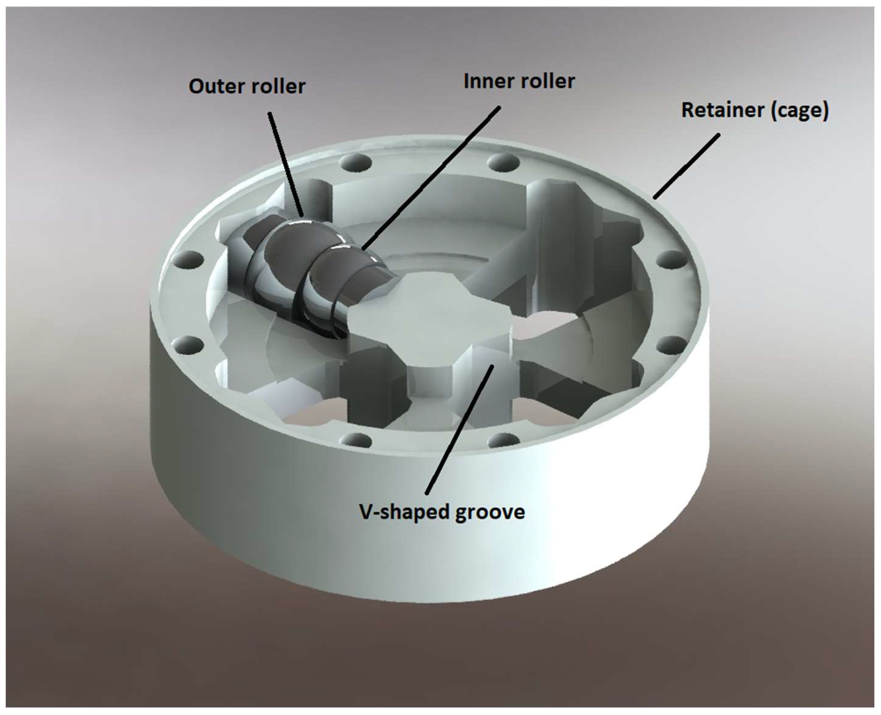
Figure 10.
Retainer (cage) with one (out of the four pairs) of outer and inner rollers within vertical grooves.
Figure 10.
Retainer (cage) with one (out of the four pairs) of outer and inner rollers within vertical grooves.

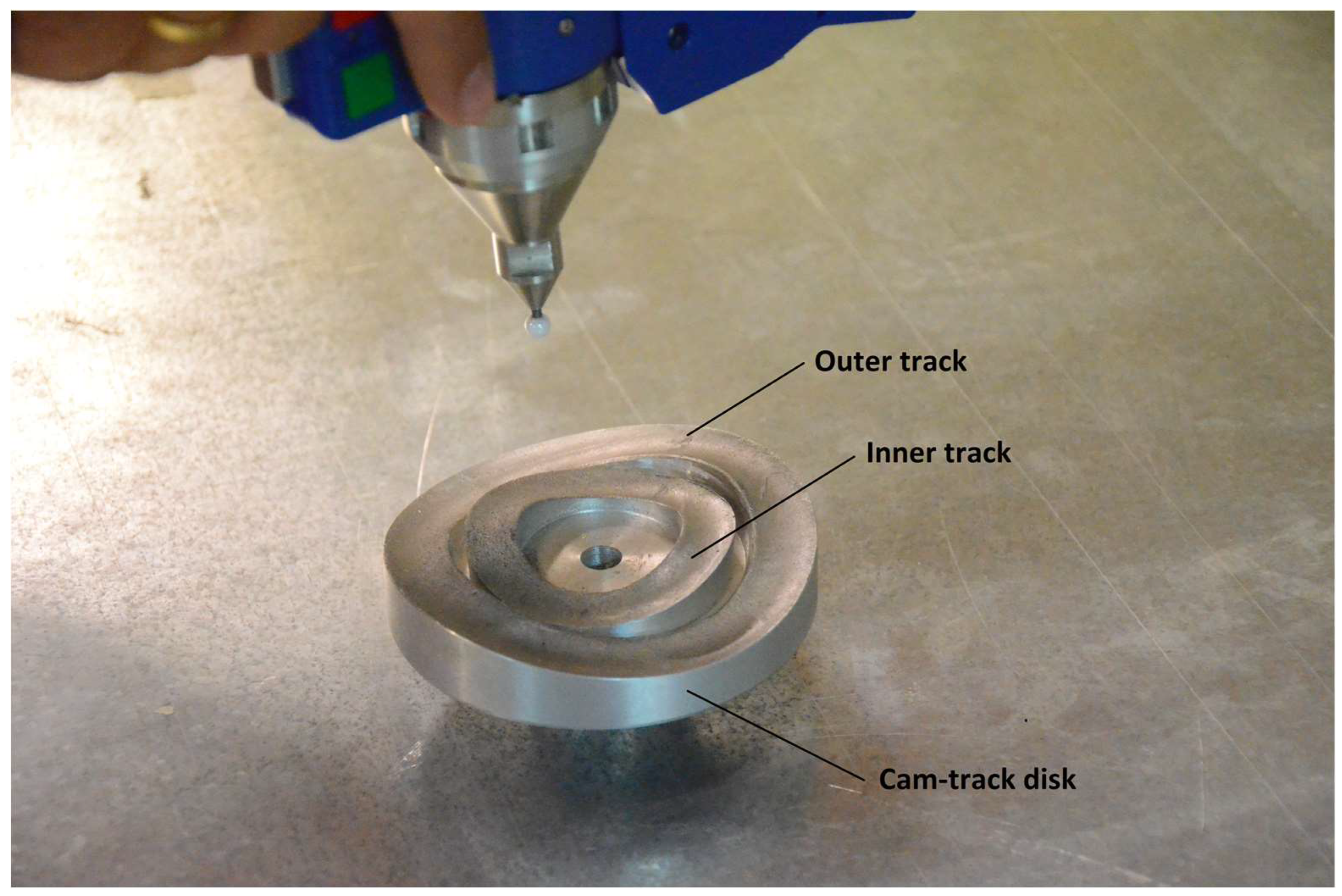
Figure 11.
Outer and inner grooves at some distance in one manufactured cam-track disk.

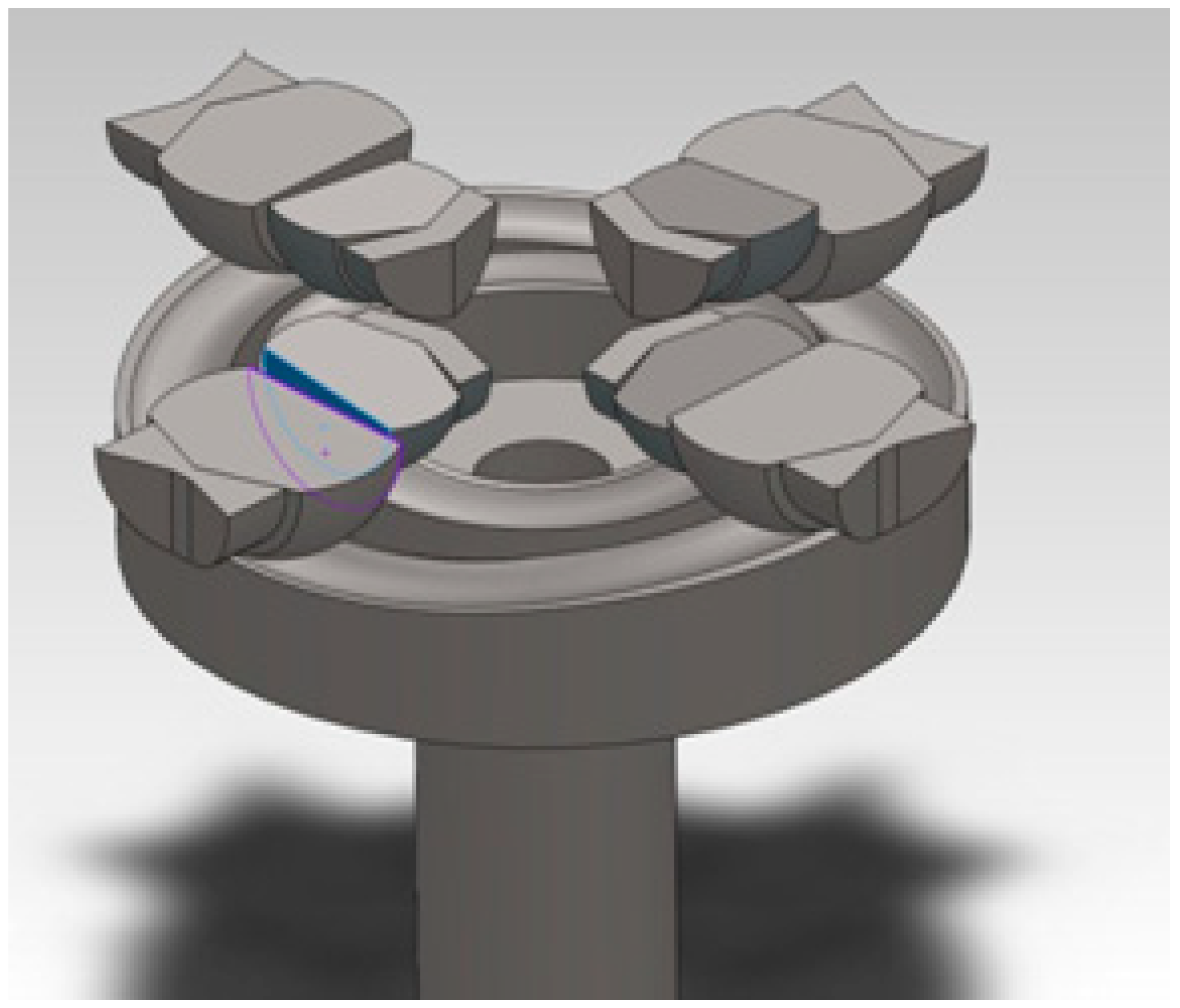
Figure 12.
A complete cam-track disk with all the rolling members (the blue-colored area shows the internal contact between outer and inner rollers).
Figure 12.
A complete cam-track disk with all the rolling members (the blue-colored area shows the internal contact between outer and inner rollers).

Figure 13.
(a) One-dimensional analog of the entire differential mechanism as well as force equilibrium of (b) the upper cam-track disk and (c) the roller (ignoring the friction at grooves).
Figure 13.
(a) One-dimensional analog of the entire differential mechanism as well as force equilibrium of (b) the upper cam-track disk and (c) the roller (ignoring the friction at grooves).

Figure 14.
Analysis of circumferential force (a) at a wedge (b) in two components normal to the upper and lower track. The projection of is the axial force .
Figure 14.
Analysis of circumferential force (a) at a wedge (b) in two components normal to the upper and lower track. The projection of is the axial force .

Figure 15.
Several phases of the cam tracks, for relative rotation every , for the outer track and the inner track (uniform scale). (a) . (b) . (c) . (d) . (e) . (f) . (g) . (h) . (i) .
Figure 15.
Several phases of the cam tracks, for relative rotation every , for the outer track and the inner track (uniform scale). (a) . (b) . (c) . (d) . (e) . (f) . (g) . (h) . (i) .

Figure 16.
Cam-track disks with outer tracks (a) in parallel state and (b) maximum wedge angle.


Table 1.
Parameters of the model.
| Parameter | Value |
|---|---|
| Input torque (applied to the crown attached to the cage/retainer) | 260 Nm |
| Number of rolling elements at each cam track | 4 |
| Phase-difference between outer and inner cam track | 45° |
| Diameter of outer cam track: | 85 mm |
| Diameter of inner cam track: | 50 mm |
| Radius of rolling element in the outer track: | 15 mm |
| Radius of rolling element in the inner track: | 12 mm |
| Outer diameter of friction disk: | 95 mm |
| Inner diameter of friction disk: | 45 mm |
| Coefficient of friction: | 0.066 |
| Inclination angle (half the central angle) of outer track: | 15° |
| Inclination angle (half the central angle) of inner track: | 27.25° |
Table 2.
Calculated stresses (in GPa).
| Simplified Model | Finite Element Analysis (Ref. [23]) | ||
|---|---|---|---|
| Outer Track | Inner Track | Outer Track | Inner Track |
| 1.6 | 1.2 | 1.3 | 0.8 |
Table 3.
Calculated stresses (in GPa) for varying curvatures of the tracks.
| Simplified Model: Equation (30) | |||
|---|---|---|---|
| Outer Track | Inner Track | Outer Track | Inner Track |
| 1.57 | 1.20 | ||
| 1.52 | 1.16 | ||
| 1.46 | 1.12 | ||
| 1.40 | 1.07 | ||
| 1.34 | 1.02 | ||
| 1.26 | 0.96 | ||
| 1.18 | 0.90 | ||
Table 4.
Calculated stresses (in GPa) for varying inclination angles of the tracks.
| Simplified Model: Equation (30) | |||
|---|---|---|---|
| Outer Track | Inner Track | Outer Track | Inner Track |
| 1.5211 | 1.1611 | ||
| 1.5690 | 1.1953 | ||
| 1.6239 | 1.2351 | ||
Disclaimer/Publisher’s Note: The statements, opinions and data contained in all publications are solely those of the individual author(s) and contributor(s) and not of MDPI and/or the editor(s). MDPI and/or the editor(s) disclaim responsibility for any injury to people or property resulting from any ideas, methods, instructions or products referred to in the content. |
© 2023 by the author. Licensee MDPI, Basel, Switzerland. This article is an open access article distributed under the terms and conditions of the Creative Commons Attribution (CC BY) license (https://creativecommons.org/licenses/by/4.0/).
Share and Cite
MDPI and ACS Style
Provatidis, C.G. Power Transmission Using Circular Elements Bounded by Given Central Angle in Rolling Contact. Eng 2023, 4, 2309-2335. https://doi.org/10.3390/eng4030132
AMA Style
Provatidis CG. Power Transmission Using Circular Elements Bounded by Given Central Angle in Rolling Contact. Eng. 2023; 4(3):2309-2335. https://doi.org/10.3390/eng4030132
Chicago/Turabian StyleProvatidis, Christopher G. 2023. "Power Transmission Using Circular Elements Bounded by Given Central Angle in Rolling Contact" Eng 4, no. 3: 2309-2335. https://doi.org/10.3390/eng4030132