
A Review of Dielectric Resonator Antenna at Mm-Wave Band

1
Electrical Engineering Department, Jouf University, Sakaka 72388, Aljouf, Saudi Arabia
2
Communications Research Group, Department of Electronic and Electrical Engineering, The University of Sheffield, Mappin Street, Sheffield S1 3JD, UK
Eng 2023, 4(1), 843-856; https://doi.org/10.3390/eng4010051
Submission received: 27 January 2023
/
Revised: 20 February 2023
/
Accepted: 1 March 2023
/
Published: 6 March 2023
(This article belongs to the Section Electrical and Electronic Engineering)
Abstract
:This paper is a comprehensive review of the recent literature studies on the developments and applications of millimeter-wave (mm-wave) dielectric resonator antennas (DRAs). Different designs and techniques for linear and circular polarized DRAs are discussed thoroughly. In addition, array and multiple-input multiple-output (MIMO) DRAs operating in the K, Ka, and V bands are illustrated. These applications are highly advantageous on many levels, resulting in the improved performance of the DRA in terms of obtaining a higher gain, lower losses, a higher efficiency, and a lower profile. This work reviews the fundamental research trends in antennas to meet the demands of fifth-generation (5G) communications and beyond. The reviewed studies are scholarly sources which contain measurement-based results. This paper concludes by highlighting the limitations of the studies and the implications for future research.
1. Introduction
Wireless communications have extensively focused on lower frequency bands (LF) that operate on a frequency that ranges from 300 kHz to 3 GHz. As a result of the substantial increment in the number of mobile devices and customers, the bandwidth of the microwave band is becoming inadequate [1]. Consequently, mobile users face problems while trying to achieve a very high speed, low latency, and good coverage, as the quality of the service is ultimately reduced [2]. On the other hand, it is evident that the wide bandwidths at higher frequencies offer transmission rates of several gigabits per second despite the wide-scale establishments [3]. The 5th-generation network (5G) is the latest wireless communication system. Even though its intended objective was to facilitate mobile users’ communication, it is evident that massive architectures, like the Internet of Things (IoT) and institutional systems, have also been applied. However, terminal devices that operate through 5G networks have become more accessible at a limited frequency below 6 GHz.
In this context, it is essential to explore operating bandwidths at higher frequencies [4]. For example, the millimeter-wave (mm-wave) frequency range has been identified as a potential band [5]. A white paper developed by the MiWaveS, a project established in 2015 and funded by the European Union, suggested the development of technologies to access mm-wave wireless and backhaul [6]. In 2016, the Federal Communications Commission (FCC) of the United States introduced four frequency bands to develop 5G mm-wave communication systems and to research further. The US vendors in the field of communication deployed the four frequency bands. Further, acquiring a key position in the global mm-wave mobile communication technology was attempted [7]. Contemporarily, US wireless communications operators such as Verizon, T-Mobile, and AT and T acquired the license to use the mm-wave spectrum. In particular, Verizon has dynamically promoted the indoor placement of mm-wave systems. In China, the ministries of Industry and Information Technology, Science and Technology, and the National Development and Reform Commission cooperatively worked to launch the 5G band of IMT-2020. The team is responsible for studying issues related to the 5G spectrum [8]. China provided a commercial license for 5G in 2019 [9], enabling its telecommunications operators to introduce 5G-related services.
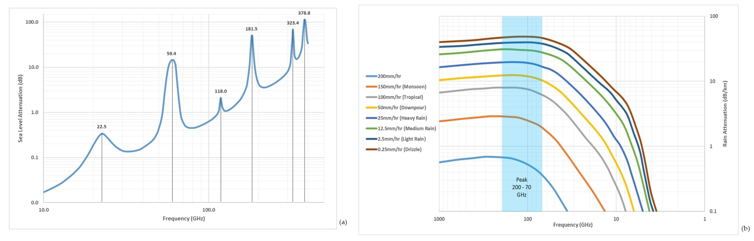
On the other hand, there are limitations concerning mm-wave frequencies, such as short-range communications and maintaining line of sight. The main factors that affect the transmission range are short wavelengths (1–10 mm) and high atmospheric attenuation caused by fog, rain, or moisture (Figure 1). As a result, this has triggered a significant interest in designing high-gain antennas and arrays to improve the radiated power over an enhanced transmission range. In contrast to other communication systems that operate at lower frequencies, the mm-wave communication systems have a higher propagation loss. At the 60 GHz band, the multi-path is conventional with directional antennas because of the small-scale propagation effects [10]. In addition to the attained high data rates at 60 GHz, the energy propagation at this frequency has characteristics that make it suitable for use to obtain high security, high immunity to interference, and frequency re-use. The mm-wave frequencies that range between 28 GHz and 38 GHz are appropriate for use in 5G and Beyond-5G communication systems. Therefore, previous studies propose the employment of 28 GHz and 38 GHz mm-wave frequencies in Hyperconnected F-RANs. Furthermore, the use of the mm-wave at 28 GHz, 38 GHz, and 71–76 GHz is useful because it can operate at the 5G enhanced local area (eLA). It is evident that the eLA system can attain high data rates in the excess and edge that would be 10 Gbps and more than 100 Mbps, respectively [11].
2. Dielectric Resonator Antenna
In 1939, R. D. Richtmyer, who studied the resonant properties of dielectric materials in different shapes such as spherical, ring, and toroidal, predicted the concept of generating electromagnetic radiation from such dielectric geometries [13]. Nevertheless, such a concept was unpopular among scientists as low-loss dielectric materials were unavailable. Later, the scientists developed dielectric resonators (DRs) of cylindrical, rectangular, and hemispherical geometries, utilizing materials with high permittivity and low losses that have received considerable popularity [14]. Due to the advancements in the ceramic industry and the accessibility to low-loss dielectric materials, in the early 1960s, the use of dielectric resonators was initiated to provide a substitute for metallic microwave resonators.
Hence, the preliminary research on dielectric resonators focused on their electronic applications, particularly in oscillators and filters [15,16]. In 1962, Okaya and Barash reported that rutile crystals with low dielectric losses could provide an unloaded quality factor (Q) more significant than that of cavity resonators with metal walls [17]. Gastine et al. discovered the radiation Q-factor of isolated spherical dielectric resonators in 1967 [18]. Many research studies have been conducted to investigate the electromagnetic field distribution of the modes and nomenclature in dielectric resonators with a high dielectric constant [19,20,21,22]. Accordingly, during this period, there was an exploration of the potential of using dielectric resonators as circuit elements and their properties to see if they are convenient in such applications.
Based on the objectives, dielectric resonators are covered by a metallic cavity to keep the Q-factor high and hence reduce radiation leaks. However, when the metallic cover is removed and the dielectric constant is reduced, dielectric resonators can act as effective radiators of electromagnetic waves. Therefore, scientists developed dielectric resonator antennas (DRAs) based on this concept, and this was the transition period of dielectric resonators from circuit components to radiating elements. This transition was because the electromagnetic fields could leak out of the cavity when the metallic enclosure is removed.
Accordingly, dielectric resonators can radiate when their permittivity is reduced and the metallic surrounding is removed. The systematic study on the use of dielectric resonators as antenna elements began in the early 1980s. Long, McAllister, and Shen [22,23,24] studied the characteristics of dielectric resonator antennas with cylindrical, hemispherical, and rectangular shapes and calculated their radiation pattern theoretically. As per the findings of the research studies, DRAs exhibit a better performance than traditional metallic antennas with lower radiation efficiencies and gain. Since then, numerous research studies have focused on simple dielectric resonator shapes and possible resonance modes. In the 1990s, the researchers applied numerical and analytical methods to determine the input impedance, resonance frequency, and radiated Q-factor of DRAs of different shapes.
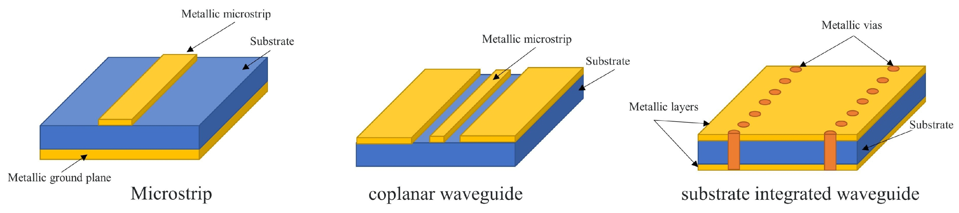
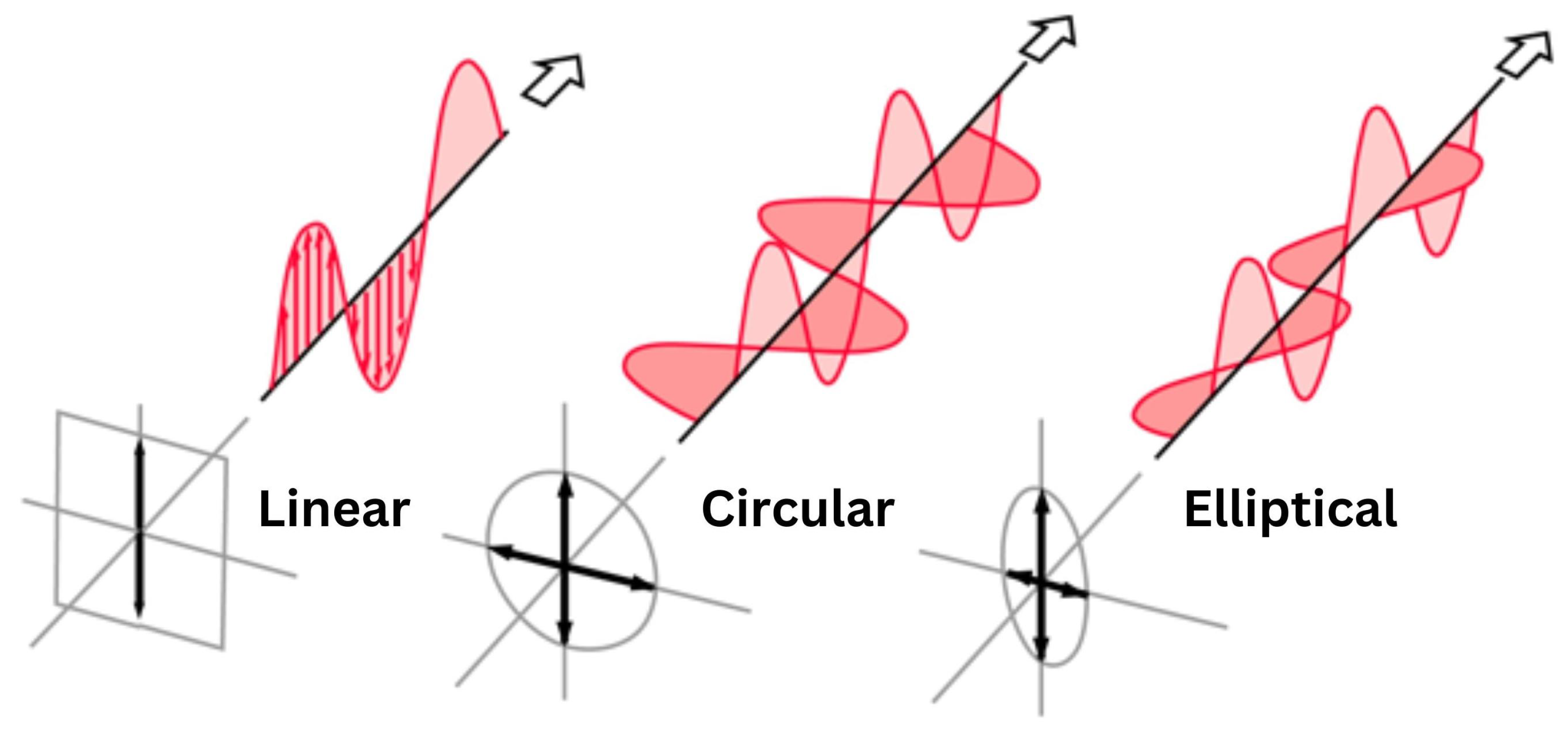
In the mid-to-late 1990s, various feeding mechanisms such as aperture coupling, probe feeding, and microstrip coupling focused on exciting dielectric resonators [25], as illustrated in Figure 2. Since 2000, and with the availability of 3D commercial electromagnetic simulators, research studies on DRAs focused on designing DRAs with improved characteristics, such as wideband, dual-band, circular polarization, as illustrated in Figure 3, high gain, reconfigurability, as well as array structures. In addition, DRAs with complex geometries and improved performances have been proposed, such as stair-shaped and trapezoidal DRAs as well as other shapes [26]. In addition, to achieve high electromagnetic coupling between the source and resonator, the DRA must be made from high dielectric constant material. Conversely, the DRAs must be made from low dielectric constant material to operate over a wide bandwidth.
3. mm-Wave Dielectric Resonator Antennas
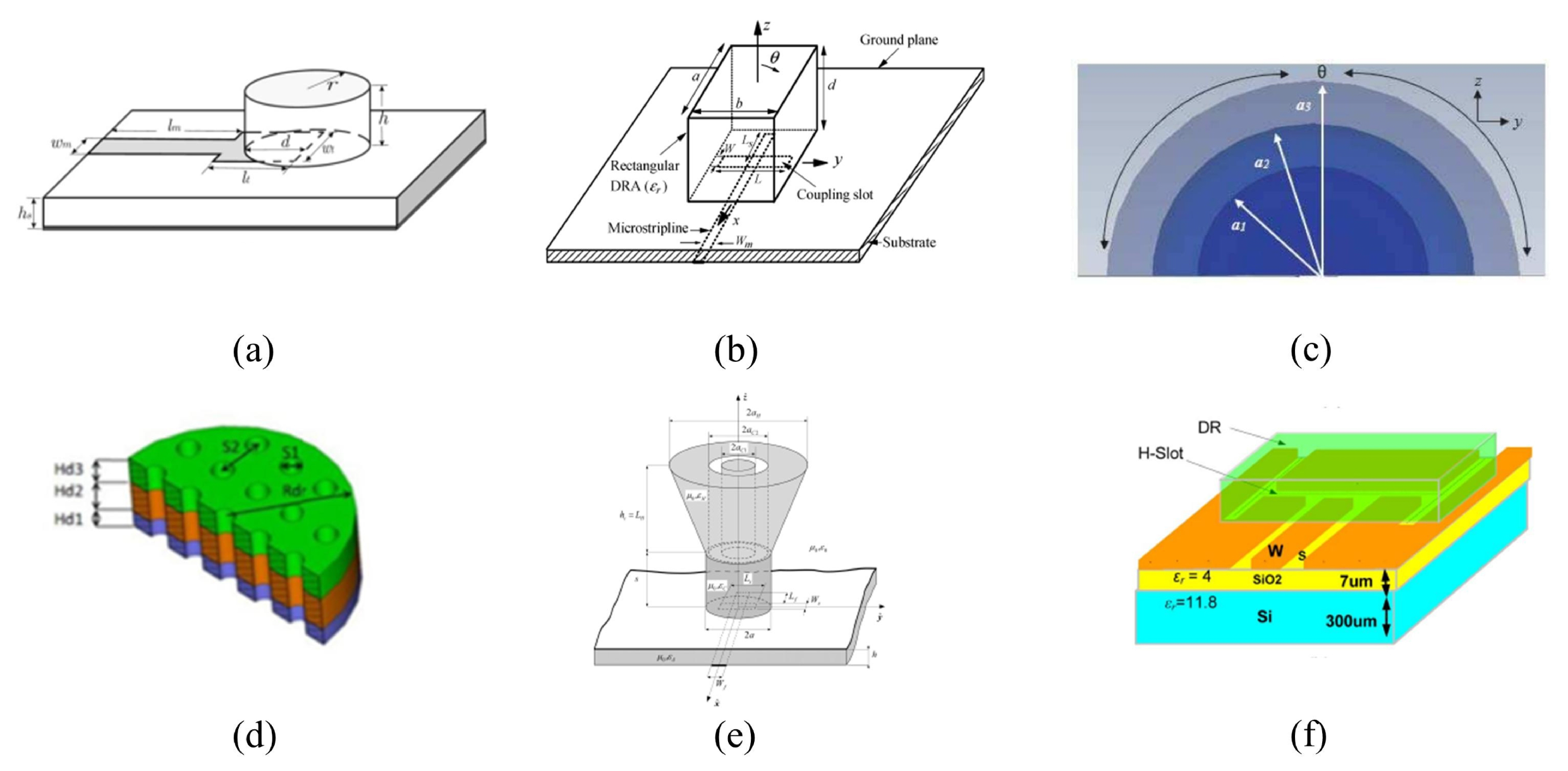
Various studies investigated the difference in the performance between DRAs and microstrip antennas (MSAs), as illustrated in Figure 4a, and concluded that the DRA is more beneficial in many aspects at higher frequencies, where ohmic losses are more significant [28]. After an analysis of the data of [28], it is safe to conclude that there are evident differences in the performance of both designs in fundamental areas. Firstly, the DRA produced a remarkable increase in bandwidth compared to the MSA. The results also illustrate an increase of ∼14% in the radiation efficiency when using the DRA, owing to the absence of ohmic losses. Furthermore, using higher-order DRA resonance modes has several benefits.
For example, the higher-order modes’ transverse electric, TE, modes and have excited the design and fabrication of larger dimensions of a DRA, as illustrated in Figure 4b, at 24 GHz to minimize fabrication errors [29]. Compared to a DRA operating in the fundamental resonance mode, , the results demonstrated DRA size increments by factors of 7 and 14.4 times when the and modes are excited. This has helped the authors of [29] to confirm that electrically large antennas (ELAs) offer a higher tolerance to fabrication errors. Additionally, the DRA has achieved an impedance bandwidth of 5.75% and a gain of 6 dBi. This study focuses on three frequency bands, namely K, Ka, and V bands, that correspond to the following frequency ranges, 18–27 GHz, 27–40 GHz, and 40–75 GHz, respectively.
A wideband high-gain three-layer mm-wave hemispherical DRA, as illustrated in Figure 4c, has been proposed in [30] with an impedance bandwidth of 35.8% and a maximum gain of 9.5 dBi as well as a radiation efficiency of 90%. One of the limitations of such a technique is the complexity of the assembly of the three dielectric layers and the higher cost. Similarly, the gain of a multilayer DRA is increased by introducing air holes, as illustrated in Figure 4d, in the antenna [31]. The study was conducted using a low-profile hybrid multi-permittivity DRA with a perforated structure for mm-wave applications. To create the air holes, the DRA is drilled to enhance the bandwidth. However, this is not possible with physically small DRAs because it would be challenging to maintain the same size and space between the air holes. In total, 21 identical cylindrical holes were created inside the dielectric resonator. The operating bandwidth has been increased by 27.4%, i.e., from 48.4% to 75.8%, without any change in the achieved gain of 5.65 dBi.
Another approach, which aimed to enhance the gain, used a DRA with a plastic-based conical horn, as illustrated in Figure 4e, for mm-wave applications [32]. The antenna was excited using a slot-coupled microstrip line with an achieved bandwidth, radiation efficiency, and gain of 16.6%, 94%, and 11.3 dBi, respectively. It is noteworthy that without the plastic-based conical horn, the gain of the DRA is 8 dBi. However, the resultant antenna configuration is complex. A different experiment that aims to increase the DRA gain was reported by [33], whereby the high-permittivity DRA has been placed over an H-slot on-chip antenna, as illustrated in Figure 4f, with an impedance bandwidth of 4.15% at 35 GHz. The measured gain and efficiency after the addition of the DRA on top of the chip are 1 dBi and 48%, respectively.
The surface-integrated waveguide (SIW) technology has been utilized to maximize the efficiency and gain of the DRA [34]. For example, a cylindrical millimeter-wave DRA has been fabricated using the Low-Temperature Co-fired Ceramics (LTCC) process to increase the gain and efficiency [35]. Instead of using a microstrip feed line, the slot has been used in an SIW, which resulted in a significant decrease in the back lobe radiation levels. This technique achieved an impedance bandwidth of 2.5%, a gain of 10.8 dBi, and an efficiency of 87%. Another study used the PCB process to fabricate a low-profile substrate-integrated dielectric resonator antenna (SIDRA) with a bandwidth of 33–36 GHz, a gain of 5.5 dBi, and an efficiency of 94% upon being fed by the SIW [34]. Furthermore, some recent research articles [36,37] have proposed the use of the Ridge Gap Waveguide (RGW) technique, which offers low-loss, low-dispersion, and high-power handling capabilities in the millimeter-wave frequency range.
Review articles were conducted to summarize some techniques for controlling the characteristics of DRAs, including feeding, size reduction, and gain enhancement, with a focus on their application at millimeter-wave frequencies in order to guide RF front-end designers in selecting appropriate antenna topologies for an optimal frequency response, gain, and polarization [38,39]. Table 1 summarized a comparison between the performance of single linear polarized DRAs at mm-wave.
3.1. Dielectric Resonator Antennas Arrays
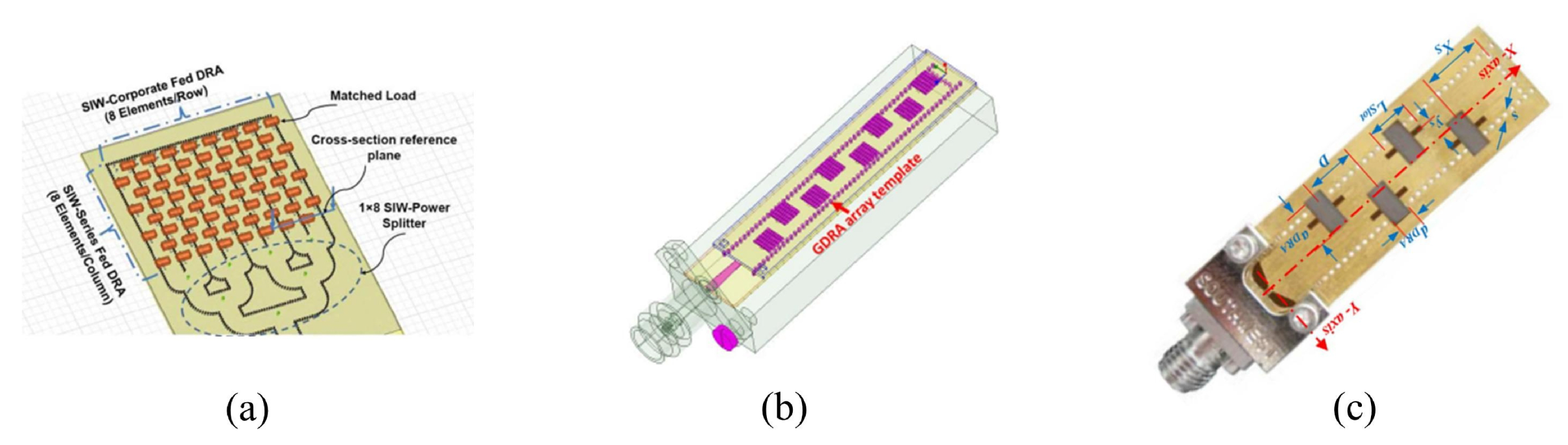
In order to increase the gain, several studies have been conducted using multiple elements to design DRA arrays. Notably, refs. [41,42,43,44] have used an SIW as a feed network. Abdel-Wahab et al. [41] conducted research that would improve the radiation efficiency using N-element linear arrays based on two different feeding slot configurations. Likewise, in another study [45], conducted by the same author of [41], an array of four DRA elements was designed using an SIW feeding network at 33.9 GHz and achieved a gain of 11.70 dBi, a bandwidth of 4.7%, and an efficiency of 90%. Yet the weakness of [41] is that it lacked a matching circuit which could have been used to improve the coupling in the SIW longitudinal slot case. Alternatively, different structures for the SIW were utilized in [42,43]. In [42], an 8 × 8 rectangular 2D DRA array, as illustrated in Figure 5a, has been proposed using an SIW hybrid feeding network. The results of the study demonstrate a gain of 22.6 dBi, bandwidth of 6.1%, and radiation efficiency of 89%. In [43], the study involved the analysis, design, and measurements of an SIW-integrated parasitic DRA array to minimize the metallic loss at the mm-wave band. The resulting gain increased from 11 dBi using four driven DRAs to 13 dBi by adding eight parasitic DRAs. The bandwidth and the efficiency remained the same at 2.5% and 91%, respectively.
Even though an SIW has also been employed in [44], the shape of the DRA is neither conventionally cylindrical nor rectangular as it is grid shaped, as illustrated in Figure 5b. It is noteworthy to mention that this is the only paper that proposes a grid shape for the DRA with a fabrication process that involves many steps. In another study [45], a gain enhancement of 5.6 dBi by using eight DRA elements, as illustrated in Figure 5c, has been demonstrated. The bandwidth has also been increased from 12.1% for a single element to 18.46% for the eight-elements array. An LTCC-fabricated integrated DRA has been proposed for 5G applications [46], where sixteen cylindrical DRA elements have been utilized. An inverted microstrip corporate feeding network has been used to feed the array and to fabricate in the same LTCC stack as the resonators. To enhance the overall performance of the array and to facilitate the alignment of the individual array elements, a grooved and grounded superstrate has been used, with an achieved bandwidth of 9.81%, gain of 15.68 dBi, and radiation efficiency of 88%.
Another DRA array design has been reported using directive LTCC-fabricated DRA elements that operate at the higher-order mode at 25.7 GHz [47]. They used an antenna array design. For an array of 1 × 4 elements, the achieved respective bandwidth, gain, and efficiency are 1%, 16.3 dBi, and 87%. Even though [46,47] have mutually proposed LTCC technology to fabricate DRA arrays, different materials have been used to fabricate the DRA and substrate in [46] compared to using the same material in [47]. A high-gain planar array with 8 × 8 elements has been proposed for mm-wave vehicular wireless communication [48], where the comparison has been reported between a series-parallel hybrid feed network and a parallel-cascaded feed network in terms of the impedance bandwidth, gain, and radiation efficiency. The series-parallel hybrid has a wider impedance bandwidth, a higher gain, and effective suppression of the sidelobes. The study also involved a comparison between the performances of the patch antenna and DRA arrays, where the latter outperformed the former.
A structure of four connected rectangular ring DRA elements has been proposed at 28 GHz [49], where glue has been utilized to reduce the air gaps between the connected DRAs and the ground plane. Moreover, to overcome the alignment limitations, dielectric arms have been added to the structure. However, it has been noted that the positions of the dielectric arms significantly affect the performance of the DRA in terms of the mutual coupling, radiation efficiency, and gain. The attained bandwidth, gain, and efficiency are 31.6%, 8 dB, and 86%, respectively. Table 2 summarized a comparison between the performance of array linear polarized DRAs at mm-wave.
3.2. V-Band Dielectric Resonator Antennas
The following section presents the studies that operated at a V-band frequency that ranges between 40 and 75 GHz. A high-gain hybrid DRA and the microstrip antenna have been proposed at 60 GHz [50], where a circular microstrip patch has been used to feed a ring-shaped DRA placed on a thin grounded dielectric layer with low permittivity. The antenna gain has improved upon the excitation of a higher-order mode. One of the limitations of such a study is the fact a superglue has been used to bond the driven patch and DRA. They have been fabricated separately using a complex manufacturing process. The resulting bandwidth is 15%, the gain is 11.9 dBi, and the radiation efficiency is 75% [50]. A micro-machined on-chip cylindrical DRA that operates at 60 GHz has been reported using high-resistivity silicon for the DRA and the feeding circuit [51]. The cylindrical DRA has been fed using a coplanar waveguide, which results in a simple and cost-effective design. The deep reactive ion etching process has been employed to etch one side of the wafer and create a cylindrical shape with respect to a radius and height of 1.18 mm and 0.4 mm. The backside of the wafer has not been etched as it acts as a substrate for the feeding structure, which has a thickness of 0.275 mm. This design results in an impedance bandwidth of 3.78%, a gain of 7 dBi, and a radiation efficiency of 79.35
A 60 GHz slot-coupled rectangular DRA, with a small size of 1 × 1 × 0.6 mm3, has been designed to attain high-efficiency monolithic integration [52]. Even though the RDRA had a small size, it resulted in an impedance bandwidth of 6.1%, a gain of 6 dBi, and an efficiency of 98%. The dielectric that was used to fabricate the DRA has been intended for on-chip system applications. The direct generation of the signal at the intrinsic port results in a maximized efficiency for the integrated mm-wave system. Hence, this proves that using intrinsic port DRAs with on-die multi-chip modules (InP MMIC) technology can result in high efficiency with a respective bandwidth and gain of 6.1% and 6 dBi. Studies [51,52] implemented different fabrication techniques of the MMIC in [52] and the micro-machine in [51]. Moreover, the shapes of the DRAs were different as well. Yet both studies design an on-chip antenna using a semiconductor material.
A compact wideband cubic DRA for 60 GHz miniature hybrid microwave integrated circuits (MHMIC) short-range transceivers has been reported in [53]. The array’s feed network consists of a rounded Wilkinson power divider that uses MHMIC technology. In contrast to the conventional T-junction power divider, the output ports of the Wilkinson power divider have high isolation which aids in eliminating any potential mismatch of the radiating elements. This provided an impedance bandwidth of 16%, a gain of 6.5 dBi, and an efficiency of more than 96%. Hence, the proposed antenna is most suitable for the MHMIC fabrication process.
In [54], the authors conducted a study that aims to increase the dimensions of the DRA, the wideband capability, and the gain performance. They proposed the use of an mm-wave rectangular DRA that would accomplish the aforementioned aims. The SIW cavity has been used as a high-pass filter. The use of the conventional backed cavity design with a 2 × 2 array demonstrated an impedance bandwidth of 8.7%. In contrast, the use of the stacked enlarged DRA demonstrated an improved impedance bandwidth of 15%. To increase this, a 4 × 4 array has been used and resulted in a significantly higher gain of 17.2 dBi.
A template-based DRA array has been presented in [55] in which cavities have been fabricated in acrylic templates in order to compose a monolithic polymer-based DRA array layer. The results demonstrate an impedance bandwidth of 12% and a gain of 10.5 dBi. The studies in refs. [53,54,55] have focused on increasing the gain through the design of 60 GHz arrays. Nevertheless, each study has utilized a different process with a different number of elements. In addition, the methods employed in [54,55] are sophisticated and expensive compared to that in [53]. Table 3 summarized a comparison between the performance of linear polarized DRAs at V band.
3.3. Multiple-Input and Multiple-Output (MIMO) Dielectric Resonator Antenna
Mutual coupling between MIMO elements can drastically affect the antenna characteristics by reducing the performance of the MIMO systems. Hence, studies have been conducted to examine the efficient approaches that can be utilized to reduce the mutual coupling between the MIMO elements, by incorporating metamaterials walls [56,57], and the mutual coupling was significantly reduced. Table 4 summarized a comparison between the performance of MIMO DRAs at V band.
In [56], a metasurface shield has been used for 60 GHz MIMO systems and a 1 × 7 elements array of the split-ring resonators with a respective bandwidth, gain, and efficiency of 13%, 7.9 dBi, and 91%. On the other hand, a metamaterial polarization rotator wall has been used to reduce the spatial electromagnetic fields between two DRAs in a MIMO system with a respective bandwidth and efficiency of 13.3% and 88% [57].
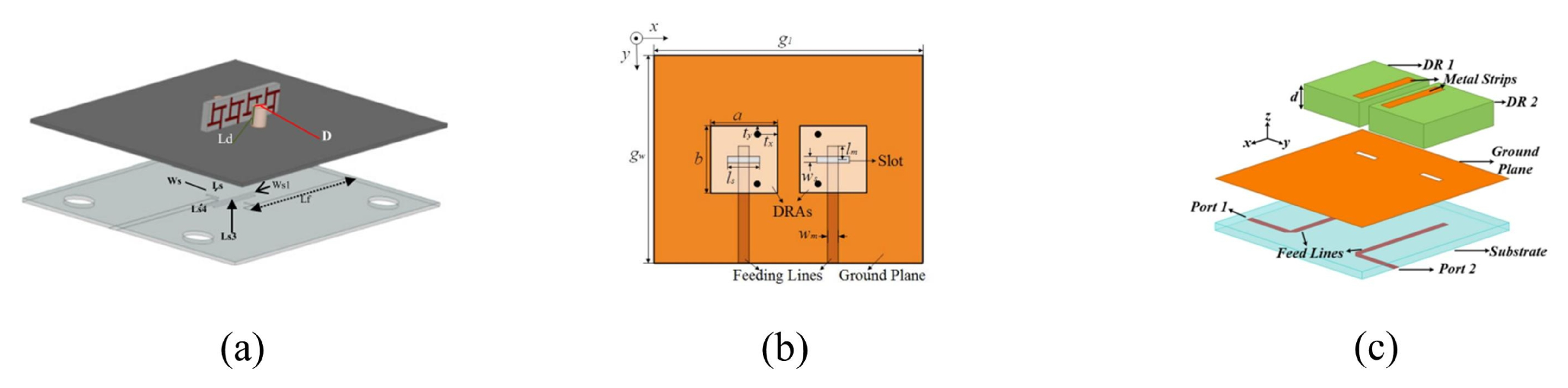
A low-mutual-coupling 60 GHz MIMO antenna system with a frequency selective surface (FSS) wall, as illustrated in Figure 6a, to increase isolation has been reported [58]. The usage of an FSS wall resulted in an insertion loss enhancement of more than 15 dB. However, using the FSS wall and slots resulted in the achievement of better isolation, that is, 30 dB. These methods demand an element spacing of more than 0.6 , which is relatively large and can result in a higher profile. Therefore, these methods are not applicable in the development of dense arrays.
A simple decoupling method has been used and proposed to improve the isolation using metallic vias [59], as illustrated in Figure 6b. The decoupling and self-decoupled methods have been mainly focused on two-element arrays and do not provide approaches that can be applied on massive MIMO arrays with a bandwidth of 7.3% and gain of 6 dBi. Similarly, another study has been conducted using a similar technique to enhance the isolation among the DRA elements with a bandwidth of 4.8% and a gain of 9.9 dBi [60]. It should be noted that metal vias have been used in [59], whereas metal microstrips have been utilized in [60]. Antennas that have metallic patches as radiating elements, as evident in these studies, lead to lower radiation efficiencies, as illustrated in Figure 6c. This could be remedied through the use of DRAs. The efficiency has not been mentioned in these two studies because it is relatively low due to the use of metallic patches as radiating elements.
A Ka-band frequency of 30 GHz has been designed using two MIMO arrays of eight-element linear cylindrical DRAs [61]. A passive microstrip feed network has been implemented to excite the design. Nevertheless, the achieved isolation achieved 15dB, which is considered low as the works of literature report [58]. The achieved bandwidth is 3.33%, the gain is 7dBi, and the efficiency is 80%.
In a recent study [62], a MIMO DRA has been used at 28 GHz, which has been excited using a rectangular slot at the fundamental resonance mode. Two simple metallic sheets have been symmetrically embedded into the DRA to minimize the mutual coupling. The attained isolation is 17 dB. The bandwidth and gain attained are 3.9% and 6 dBi, respectively. The method used to embed the metallic sheets into the DRA has not been extensively clarified in the study. This poses a limitation on the study because the technique needs to be accurate to avoid fabrication errors that could potentially affect the performance of the antenna in future studies.
3.4. Circularly Polarized Dielectric Resonator Antenna
The section below illustrates studies that have been conducted on mm-wave CP DRAs at K and Ka bands, Section 3.4.1, as well as the V band, Section 3.4.2. Table 5 compares the performance of various mm-wave CP DRAs.
3.4.1. CP Dielectric Resonator Antenna at K and Ka Bands
Conventionally, the feed structure and DRA are designed and fabricated using different dielectric materials. When mounting the DRA on the feed network, errors are expected, which would significantly affect the antenna’s performance. This is especially the case if the operation takes place in the millimeter-wave band. To minimize the aforementioned errors, the integrated DRA substrate concept has been proposed by designing the four DRA elements and feed network together, using the same material and fabrication process. This method has been implemented in [64] with an achieved bandwidth of 1.6% and gain of 13.6 dBi for the linear polarization case. On the other hand, a bandwidth of 16.48% and a gain of 12.7 dBi have been achieved for the CP antenna with an axial ratio bandwidth of 1.1%. One of the limitations of [64] is the fact that no attention has been paid to the element’s profile.
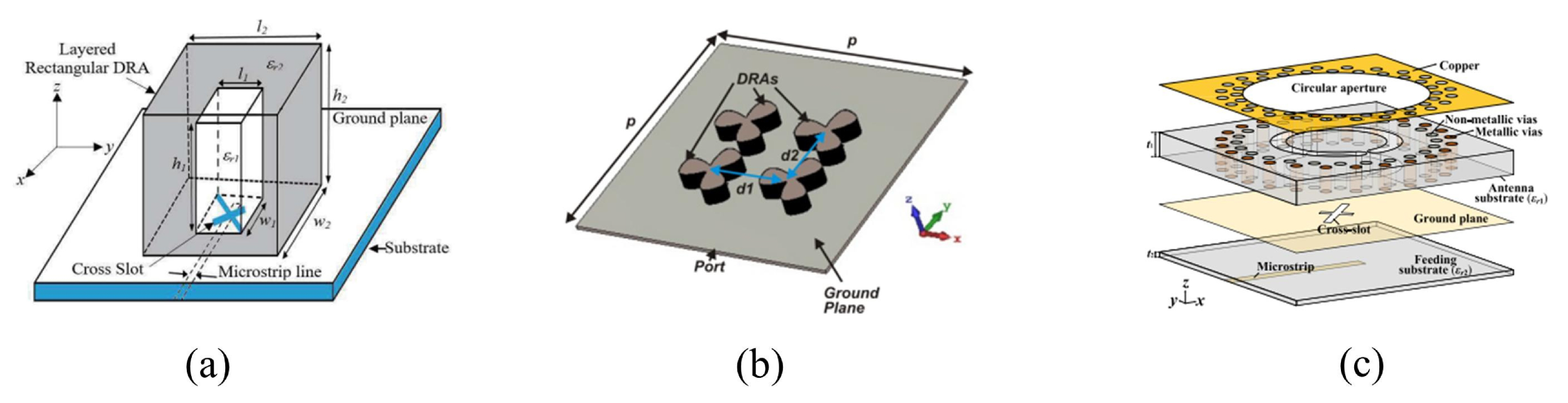
A wide bandwidth high-gain circularly polarized mm-wave rectangular dielectric resonator antenna has been reported [65], where a two-layer DRA has been utilized, as illustrated in Figure 7c. By adding the coating layer, a CP bandwidth of 13.75% has been achieved in conjunction with an impedance bandwidth of 36.5% and a gain of 12.5 dBi. However, using two different materials increases the complexity and cost of the design.
A wideband circularly polarized substrate-integrated dielectric resonator antenna (CP SIDRA) has been reported with the respective gain, impedance, and CP bandwidth of 8.15 dBi, 34.6%, and 26.3% [66]. However, this technique is expensive and sophisticated, with a relatively large size. An experiment has been conducted on a wideband CP 2 × 2 DRA array with a feed that consists of sequential networks and cross-slots [67]. Each unit element is 90 degrees from the adjacent element, and the results demonstrate an impedance and a CP bandwidth of 33.8% and 5%, respectively, with a gain of 9.5 dBi. In [68], the authors proposed a CPDRA that would operate at 24 GHz. Remarkably, their aim was to design a larger DRA, and they achieved that by operating the antenna at a higher mode of . A rectangular DRA and three rectangular slots make up the antenna structure, such that one of the slots is at the center, and the two other slots are equilaterally inclined with regard to the center slot. The results illustrate that when the antenna operated at the higher mode of , the antenna size was increased by 61%. A phase difference was provided by the two stubs and the main microstrip feed that are used to design the modified microstrip. The study achieved an impedance bandwidth of 15.06%, a gain of 7.9 dBi, and an axial ratio of 5.8% [68].
The studies above operated at a Ka-band frequency. Yet the main difference between them is that they incorporated different structures onto or under the DR to increase the CP band. For instance, in [65,66], both used a cross-slot with unequal lengths. The authors [67] combined sequential networks and cross-slots, as illustrated in Figure 7a. Nevertheless, in [64,68], they incorporated different structures as they used U-metal strip patterns on the DR and three rectangular slots with two stubs at the feed network, respectively. In addition to that, the aforementioned studies, except [65], have not mentioned the radiation efficiency due to the use of material that results in a reduction in the radiation efficiency.
Recent studies have been conducted to achieve the CP bandwidth using DRAs with different shapes and to measure their performance in terms of the bandwidth, gain, efficiency, and axial ratio. In [69], a trapezoid DRA has been used at a frequency of 26 GHz, and the bandwidth and the axial ratio attained are equal to 26.3% and 5.2%. Yet there have been fabrication errors that may have resulted from the angular cuts of the rectangular DRA structure into a trapezoid.
In [70], a cylindrical DRA has been used at a frequency of 26 GHz, which is excited using the coaxial probe, such that the DRA is drilled. This is a complex procedure, and it has not been implemented by many studies. There needs to be a high tolerance for fabrication. To convert the LP to CP, the metasurface is applied. The axial ratio and gain are improved significantly when the metasurface is applied. The CP bandwidth is 26.3%, and the axial ratio is 1.35%. In [72], a stacked rectangular DRA structure has been used at a dual frequency of 20 GHz and 30 GHz, which is excited using an SIW feed. Two rectangular DRAs are stacked on top of each other, and a metal strip is placed on top of the second DRA to obtain the CP in both frequency bands. However, this process is complicated and costly because it demands numerous steps and materials. At 20 GHz and 30 GHz, the CP bandwidth attained is equal to 6.4% and 12.8%, respectively, and the axial ratio attained is equal to 5.2% and 4.1%, respectively. It is remarkable that, in the study, the alignment has not been sufficiently addressed when it should have been given critical attention because the structure is complex.
3.4.2. Dielectric Resonator Antenna at V Band
This section presents the studies that operate at a frequency of 60 GHz. The chief difference between them is that in [73], the researchers used a cross slot and a half-mode SIW, whereas in [74], they loaded the DR with a slotted circular patch at the top, as illustrated in Figure 7b. In [73], aperture-coupled cylindrical DRAs that are fed by a half-mode SIW (HMSIW) were proposed with a measured circular bandwidth of 4%. The CP bandwidth should be improved, but overall, the HMSIW served as efficient feeds for DRAs that operated in the mm-wave frequency band. This design achieved an efficiency between 80 and 92% [73]. The gain in the linear DRAs is 5.5 dBi and is not mentioned for the circular DRAs. At frequencies above 40 GHz, the HMSIW has the ability to present a lower attenuation constant than a standard microstrip line that is fed at the same substrate. The gain in the design is minutely affected by the variations in the glue layer in the design of the DRAs that would operate in the mm-wave band. The impedance of the whole band can be affected by a minor increase in the thickness of the glue layer. Nonetheless, it is not practical to control the thickness of the glue. Hence, it would be useful to use another method to fix the DRAs in future replications of [73].
Figure 7.
Configurations of CP antenna: (a) Layered DRA [65]; (b) Sequential array [67]; (c) Top-loaded patch [74].

In [74], a CP-SIW cylindrical DRA was proposed for mm-wave applications. Before the introduction of the loading patch, the impedance bandwidth was 5.7%. When the loading patch was added, CP radiation was produced, and the results show a bandwidth of 9.33% and a CP bandwidth of 1.35%. The CP bandwidth is narrow, so the researchers in [74] proposed 2 × 2 sequential rotation feeding to enhance the CP bandwidth to 15.9%, and the gain was 10.3 dBi. In addition to that, the gain was improved with the metalized vias as they can aid in the suppression of the back radiation and the enhancement of the front radiation. The efficiency of the experiment is between 69.9% and 98.6% [74].
4. Conclusions
This survey presents and discusses the latest advancements in DRA technology at mm-wave frequencies with respect to the design strategies that help antenna designers control the circuital features and radiation patterns of DRAs. Furthermore, numerous feeding methods are listed in the review, and their benefits and drawbacks are highlighted. It is evident that the gain of DRAs can be improved by making them resonate at suitable higher-order modes by using electrically large antennas or by incorporating horn-shaped configurations. In addition, there are multiple methods that can be applied to generate circularly polarized DRAs; however, there is a limitation in the number of studies that focus on circular polarized DRAs at the mm-wave band despite being considered to be a key solution for attenuation problems. With regard to MIMO, several techniques have been investigated in different studies. It has also been found that alternating the position of the DRAs in the MIMO is beneficial as it can maximize the channel capacity, data rate, compact size, and link reliability. With the advancements in the DRA technology, those antennas will emerge as a viable solution ahead of the well-recognized antenna types, demonstrating a performance suitable for real-world applications.
Funding
This research received no external funding.
Institutional Review Board Statement
Not applicable.
Informed Consent Statement
Not applicable.
Data Availability Statement
Not applicable.
Conflicts of Interest
The author declares no conflict of interest.
References
- Pethrick, R.A.; Hayward, D.; Jeffrey, K.; Affrossman, S.; Wilford, P. Investigation of the hydration and dehydration of aluminium oxide-hydroxide using high frequency dielectric measurements between 300 kHz-3 GHz. J. Mater. Sci. 1996, 31, 2623–2629. [Google Scholar] [CrossRef]
- Vardakas, J.S.; Monroy, I.T.; Wosinska, L.; Agapiou, G.; Brenot, R.; Pleros, N.; Verikoukis, C. Towards high capacity and low latency backhauling in 5G: The 5G STEP-FWD vision. In Proceedings of the 2017 19th International Conference on Transparent Optical Networks (ICTON), Girona, Spain, 2–6 July 2017; Volume 1, pp. 1–4. [Google Scholar]
- Budka, T.P. Wide-bandwidth millimeter-wave bond-wire interconnects. IEEE Trans. Microw. Theory Tech. 2001, 49, 715–718. [Google Scholar] [CrossRef]
- Lopez, A.V.; Chervyakov, A.; Chance, G.; Verma, S.; Tang, Y. Opportunities and Challenges of mmWave NR. IEEE Wirel. Commun. 2019, 26, 4–6. [Google Scholar] [CrossRef]
- Rappaport, T.S.; Sun, S.; Mayzus, R.; Zhao, H.; Azar, Y.; Wang, K.; Wong, G.N.; Schulz, J.K.; Samimi, M.; Gutierrez, F. Millimeter wave mobile communications for 5G cellular: It will work! IEEE Access 2013, 1, 335–349. [Google Scholar] [CrossRef]
- Parque Científico y Tecnológico de Cantabria (PCTCAN). Available online: https://tst-sistemas.com/ (accessed on 27 January 2023).
- Govindarajulu, S.R.; Alwan, E.A. Range optimization for DSRC and 5G millimeter-wave vehicle-to-vehicle communication link. In Proceedings of the 2019 International Workshop on Antenna Technology (iWAT), Miami, FL, USA, 3–6 March 2019; Volume 1, pp. 228–230. [Google Scholar]
- Medin, M.; Louie, G. The 5G ecosystem: Risks and opportunities for DoD. In Proceedings of the 2019 Defense Innovation Board, Washington, DC, USA, 3 April 2019; p. 33. [Google Scholar]
- Li, E.-L.; Wang, W.-J. 5G will drive the development of health care. Chin. Med. J. 2019, 132, 2895–2896. [Google Scholar] [CrossRef]
- Giannetti, F.; Luise, M.; Reggiannini, R. Mobile and personal communications in the 60 GHz band: A survey. Wirel. Pers. Commun. 1999, 10, 207–243. [Google Scholar] [CrossRef]
- Bani-Bakr, A.; Dimyati, K.; Hindia, M.N.; Wong, W.R.; Imran, M.A. Feasibility study of 28 GHz and 38 GHz millimeter-wave technologies for fog radio access networks using multi-slope path loss model. Phys. Commun. 2021, 47, 101401. [Google Scholar] [CrossRef]
- Zhao, Q.; Li, J. Rain attenuation in millimeter wave ranges. In Proceedings of the 2006 7th International Symposium on Antennas, Propagation & EM Theory, Guilin, China, 26–29 October 2006; Volume 1, pp. 1–4. [Google Scholar]
- Richtmyer, R. Dielectric resonators. J. Appl. Phys. 1939, 10, 391–398. [Google Scholar] [CrossRef]
- Rezaei, P.; Hakkak, M.; Forooraghi, K. Design of wide-band dielectric resonator antenna with a two-segment structure. Prog. Electromagn. Res. 2006, 66, 111–124. [Google Scholar] [CrossRef] [Green Version]
- Cohn, S.B. Microwave bandpass filters containing high-Q dielectric resonators. IEEE Trans. Microw. Theory Tech. 1968, 4, 218–227. [Google Scholar] [CrossRef]
- Fiedziuszko, S. Microwave dielectric resonators. Microw. J. 1986, 29, 189–196. [Google Scholar]
- Okaya, A.; Barash, L. The dielectric microwave resonator. Proc. IRE 1962, 50, 2081–2092. [Google Scholar] [CrossRef]
- Gastine, M.; Courtois, L.; Dormann, J.L. Electromagnetic resonances of free dielectric spheres. IEEE Trans. Microw. Theory Tech. 1967, 15, 694–700. [Google Scholar] [CrossRef]
- Kajfez, D.P.; Guillon, P. Dielectric Resonators; Noble Publishing Corporation: Atlanta, GA, USA, 1998. [Google Scholar]
- Van Bladel, J. On the resonances of a dielectric resonator of very high permittivity. IEEE Trans. Microw. Theory Tech. 1975, 23, 199–208. [Google Scholar] [CrossRef]
- Van Bladel, J. The excitation of dielectric resonators of very high permittivity. IEEE Trans. Microw. Theory Tech. 1975, 23, 208–217. [Google Scholar] [CrossRef]
- Kajfez, D.; Glisson, A.W.; James, J. Computed modal field distributions for isolated dielectric resonators. IEEE Trans. Microw. Theory Tech. 1984, 23, 1609–1984. [Google Scholar] [CrossRef]
- McAllister, M.; Long, S.A. Resonant hemispherical dielectric antenna. Electron. Lett. 1984, 20, 657–659. [Google Scholar] [CrossRef]
- McAllister, M.; Long, S.A.; Conway, G. Rectangular dielectric resonator antenna. Electron. Lett. 1983, 19, 218. [Google Scholar] [CrossRef]
- Petosa, A.; Ittipiboon, A. Dielectric resonator antennas: A historical review and the current state of the art. IEEE Antennas Propag. Mag. 2010, 52, 91–116. [Google Scholar] [CrossRef]
- Liang, X.-L.; Denidni, T.A.; Zhang, L.-N. Wideband L-shaped dielectric resonator antenna with a conformal inverted-trapezoidal patch feed. IEEE Trans. Antennas Propag. 2009, 57, 271–274. [Google Scholar] [CrossRef]
- Bhatnagar, M. Theoretical analysis and optimization of circular patch microstrip antenna. Int. Res. J. Eng. Technol. 2015, 2, 1675–1681. [Google Scholar]
- Lai, Q.; Almpanis, G.; Fumeaux, C.; Benedickter, H.; Vahldieck, R. Comparison of the radiation efficiency for the dielectric resonator antenna and the microstrip antenna at Ka band. IEEE Trans. Antennas Propag. 2008, 56, 3589–3592. [Google Scholar]
- Pan, Y.-M.; Leung, K.W.; Luk, K.-M. Design of the Millimeter-wave Rectangular Dielectric Resonator Antenna Using a Higher-Order Mode. IEEE Trans. Antennas Propag. 2011, 59, 2780–2788. [Google Scholar] [CrossRef]
- Abdulmajid, A.A.; Khamas, S.; Zhang, S. Wideband High-gain millimetre-wave three-layer hemispherical dielectric resonator antenna. Prog. Electromagn. Res. 2020, 103, 225–236. [Google Scholar] [CrossRef]
- Zubir, I.A.; Othman, M.; Ullah, U.; Kamal, S.; Ab Rahman, M.F.; Hussin, R.; Omar, M.F.; Mohammed, A.S.; Ain, M.F.; Ahmad, Z.A.; et al. A low-profile hybrid multi-permittivity dielectric resonator antenna with perforated structure for Ku and K band application. IEEE Access 2020, 8, 151219–151228. [Google Scholar] [CrossRef]
- Baldazzi, E.; Al-Rawi, A.; Cicchetti, R.; Smolders, A.B.; Testa, O.; van Coevorden Moreno, C.D.J.; Caratelli, D. A high-gain dielectric resonator antenna with plastic-based conical horn for millimeter-wave applications. IEEE Antennas Wirel. Propag. Lett. 2020, 19, 949–953. [Google Scholar] [CrossRef]
- Nezhad-Ahmadi, M.R.; Fakharzadeh, M.; Biglarbegian, B.; Safavi-Naeini, S. High-efficiency on-chip dielectric resonator antenna for mm-wave transceivers. IEEE Trans. Antennas Propag. 2010, 10, 3388–3392. [Google Scholar] [CrossRef]
- Gong, K.; Hu, X.H. Low-Profile Substrate Integrated Dielectric Resonator Antenna Implemented With PCB Process. IEEE Antennas Wirel. Propag. Lett. 2014, 13, 1023–1026. [Google Scholar] [CrossRef]
- Mrnka, M.; Cupal, M.; Raida, Z.; Pietrikova, A.; Kocur, D. Millimeter-wave directive dielectric resonator antenna based on LTCC. In Proceedings of the 2016 Loughborough Antennas & Propagation Conference (LAPC), Loughborough, UK, 14–15 November 2016; Volume 1, pp. 1–4. [Google Scholar]
- Ali, M.M.M.; Al-Hasan, M.; Mabrouk, I.B.; Denidni, T.A. Ultra-wideband hybrid magneto-electric dielectric-resonator dipole antenna Fed by a Printed RGW for Millimeter-Wave Applications. IEEE Access 2021, 10, 2028–2036. [Google Scholar] [CrossRef]
- Attia, H.; Abdalrazik, A.; Sharawi, M.S.; Kishk, A.A. Wideband Circularly-Polarized Millimeter-Wave DRA Array for Internet of Things. IEEE Internet Things J. 2023, 1. [Google Scholar] [CrossRef]
- Keyrouz, S.; Diego, C. Dielectric resonator antennas: Basic concepts, design guidelines, and recent developments at millimeter-wave frequencies. Int. J. Antennas Propag. 2023, 2016, 6075680. [Google Scholar] [CrossRef]
- Meher, P.R.; Behera, B.R.; Mishra, S.K. Design and its state-of-the-art of different shaped dielectric resonator antennas at millimeter-wave frequency band. Int. J. Microw. Comput. Eng. 2020, 30, 22221. [Google Scholar] [CrossRef]
- Alanazi, M.D.; Khamas, S.K. Wideband mm-Wave Hemispherical Dielectric Resonator Antenna with Simple Alignment and Assembly Procedures. Electronics 2022, 11, 2917. [Google Scholar] [CrossRef]
- Wahab, W.M.A.; Busuioc, D.; Safavi-Naeini, S. Low cost planar waveguide technology-based dielectric resonator antenna (DRA) for millimeter-wave applications: Analysis, design, and fabrication. IEEE Trans. Antennas Propag. 2010, 58, 2499–2507. [Google Scholar] [CrossRef]
- Abdel-Wahab, W.M.; Wang, Y.; Safavi-Naeini, S. SIW Hybrid Feeding Network-Integrated 2-D DRA Array: Simulations and Experiments. IEEE Antennas Wirel. Propag. Lett. 2016, 15, 548–551. [Google Scholar] [CrossRef]
- Abdel-Wahab, W.M.; Abdallah, M.; Anderson, J.; Wang, Y.; Al-Saedi, H.; Safavi-Naeini, S. SIW-integrated parasitic DRA array: Analysis, design, and measurement. IEEE Antennas Wirel. Propag. Lett. 2018, 18, 69–73. [Google Scholar] [CrossRef]
- Mazhar, W.; Klymyshyn, D.M.; Wells, G.; Qureshi, A.A.; Jacobs, M.; Achenbach, S. Low-profile artificial grid dielectric resonator antenna arrays for mm-wave applications. IEEE Trans. Antennas Propag. 2019, 67, 4406–4417. [Google Scholar] [CrossRef]
- Abdel-Wahab, W.M.; Busuioc, D.; Safavi-Naeini, S. Millimeter-Wave High Radiation Efficiency Planar Waveguide Series-Fed Dielectric Resonator Antenna (DRA) Array: Analysis, Design, and Measurements. IEEE Trans. Antennas Propag. 2011, 59, 2834–2843. [Google Scholar] [CrossRef]
- Niayesh, M.; Kouki, A. LTCC-Integrated Dielectric Resonant Antenna Array for 5G Applications. Sensors 2021, 21, 3801. [Google Scholar] [CrossRef]
- Mrnka, M.; Cupal, M.; Raida, Z.; Pietrikova, A.; Kocur, D. Millimetre-wave dielectric resonator antenna array based on directive LTCC elements. IET Microwaves Antennas Propag. 2018, 12, 2662–2667. [Google Scholar] [CrossRef]
- Luo, W.; Shi, L.; Xu, W.; Chen, W.; Yang, Y.; Ren, Y. High gain dielectric resonance antenna array for millimeter wave vehicular wireless communication. Prog. Electromagn. Res. C 2021, 108, 63–78. [Google Scholar] [CrossRef]
- Liu, Y.T.; Ma, B.; Huang, S.; Wang, S.; Hou, Z.J.; Wu, W. Wideband Low-Profile Connected Rectangular Ring Dielectric Resonator Antenna Array for Millimeter-Wave Applications. IEEE Trans. Antennas Propag. 2022, 71, 999–1004. [Google Scholar] [CrossRef]
- Perron, A.; Denidni, T.A.; Sebak, A.R. High-Gain Hybrid Dielectric Resonator Antenna for Millimeter-Wave Applications: Design and Implementation. IEEE Trans. Antennas Propag. 2009, 57, 2882–2892. [Google Scholar] [CrossRef]
- Sallam, M.O.; Serry, M.; Sedky, S.; Shamim, A.; De Raedt, W.; Vandenbosch, G.A.; Soliman, E.A. Micromachined on-chip dielectric resonator antenna operating at 60 GHz. IEEE Trans. Antennas Propag. 2015, 63, 3410–3416. [Google Scholar] [CrossRef] [Green Version]
- Ohlsson, L.; Bryllert, T.; Gustafson, C.; Sjöberg, D.; Egard, M.; Ärlelid, M.; Wernersson, L.E. Slot-coupled millimeter-wave dielectric resonator antenna for high-efficiency monolithic integration. IEEE Trans. Antennas Propag. 2012, 61, 1599–1607. [Google Scholar] [CrossRef]
- Ardakani, M.D.; Farahani, M.; Akbari, M.; Tatu, S.O. A compact wideband cubic dielectric resonator antenna for integrated 60-GHz MHMIC short-range transceivers. In Proceedings of the 2020 IEEE International Symposium on Antennas and Propagation and North American Radio Science Meetin, Montreal, QC, Canada, 5–10 July 2020. [Google Scholar]
- Chen, Z.; Shen, C.; Liu, H.; Ye, X.; Qi, L.; Yao, Y.; Yu, J.; Chen, X. Millimeter-wave rectangular dielectric resonator antenna array with enlarged DRA dimensions, wideband capability, and high-gain performance. IEEE Trans. Antennas Propag. 2019, 68, 3271–3327. [Google Scholar] [CrossRef]
- Qureshi, A.A.; Klymyshyn, D.M.; Tayfeh, M.; Mazhar, W.; Börner, M.; Mohr, J. Template-based dielectric resonator antenna arrays for millimeter-wave applications. IEEE Trans. Antennas Propag. 2017, 65, 4576–4584. [Google Scholar] [CrossRef]
- Dadgarpour, A.; Zarghooni, B.; Virdee, B.S.; Denidni, T.A.; Kishk, A.A. Mutual coupling reduction in dielectric resonator antennas using metasurface shield for 60-GHz MIMO systems. IEEE Antennas Wirel. Propag. Lett. 2016, 16, 477–4804. [Google Scholar] [CrossRef] [Green Version]
- Farahani, M.; Pourahmadazar, J.; Akbari, M.; Nedil, M.; Sebak, A.R.; Denidni, T.A. Mutual coupling reduction in millimeter-wave MIMO antenna array using a metamaterial polarization-rotator wall. IEEE Antennas Wirel. Propag. Lett. 2017, 16, 2324–2327. [Google Scholar] [CrossRef]
- Karimian, R.; Kesavan, A.; Nedil, M.; Denidni, T.A. Low-mutual-coupling 60-GHz MIMO antenna system with frequency selective surface wall. IEEE Antennas Wirel. Propag. Lett. 2016, 16, 373–376. [Google Scholar] [CrossRef]
- Pan, Y.M.; Qin, X.; Sun, Y.X.; Zheng, S.Y. A simple decoupling method for 5G millimeter-wave MIMO dielectric resonator antennas. IEEE Trans. Antennas Propag. 2019, 67, 2224–2234. [Google Scholar] [CrossRef]
- Zhang, Y.; Deng, J.-Y.; Li, M.-J.; Sun, D.; Guo, L.-X. A MIMO dielectric resonator antenna with improved isolation for 5G mm-wave applications. IEEE Antennas Wirel. Propag. Lett. 2019, 18, 747–751. [Google Scholar] [CrossRef]
- Sharawi, M.S.; Podilchak, S.K.; Hussain, M.T.; Antar, Y.M. Dielectric resonator based MIMO antenna system enabling millimetre-wave mobile devices. IET Microwaves Antennas Propag. 2017, 11, 87–293. [Google Scholar] [CrossRef] [Green Version]
- Sahu, N.K.; Gangwar, R.K. Dual-Port Compact MIMO-DRAs: Exploiting Metallic Sheets to Increase Inter-Port Isolation at 28 GHz 5G-Band. IEEE Trans. Circuits Syst. II Express Briefs 2022, 69, 4814–4818. [Google Scholar] [CrossRef]
- Alanazi, M.D.; Khamas, S.K. A Compact Dual Band MIMO Dielectric Resonator Antenna with Improved Performance for mm-Wave Applications. Sensors 2022, 22, 5056. [Google Scholar] [CrossRef] [PubMed]
- Chu, H.; Guo, Y.-X. A novel approach for millimeter-wave dielectric resonator antenna array designs by using the substrate integrated technology. IEEE Trans. Antennas Propag. 2016, 65, 909–914. [Google Scholar] [CrossRef]
- Abdulmajid, A.A.; Khamas, S.; Zhang, S. Wide bandwidth high gain circularly polarized millimetre-wave rectangular dielectric resonator antenna. Prog. Electromagn. Res. M 2020, 89, 171–177. [Google Scholar] [CrossRef] [Green Version]
- Yang, M.D.; Pan, Y.M.; Sun, Y.X.; Leung, K.W. Wideband circularly polarized substrate-integrated embedded dielectric resonator antenna for millimeter-wave applications. IEEE Trans. Antennas Propag. 2019, 68, 1145–1150. [Google Scholar] [CrossRef]
- Kesavan, A.; Al-Hassan, M.A.; Ben Mabrouk, I.; Denidni, T.A. Wideband circular polarized dielectric resonator antenna array for millimeter-wave applications. Sensors 2021, 21, 3614. [Google Scholar] [CrossRef]
- Bansal, A.; Vaish, A. Deminiaturized mode control rectangular dielectric resonator antenna. Prog. Electromagn. Res. 2016, 86, 173–182. [Google Scholar]
- Gaya, A.; Jamaluddin, M.H.; Alali, B.; Althuwayb, A.A. A novel wide dual band circularly polarized dielectric resonator antenna for milli meter wave 5G applications. Alex. Eng. J. 2022, 61, 10791–10803. [Google Scholar] [CrossRef]
- Zhao, G.; Zhou, Y.; Wang, J.R.; Tong, M.S. A circularly polarized dielectric resonator antenna based on quasi-self-complementary metasurface. IEEE Trans. Antennas Propagationl 2022, 8, 7147–7151. [Google Scholar] [CrossRef]
- Alanazi, M.D.; Khamas, S.K. Wideband Circularly Polarized Millimeter Wave Hemispherical Dielectric Resonator Antenna. Micromachines 2023, 14, 436. [Google Scholar] [CrossRef] [PubMed]
- Xu, H.; Chen, Z.; Liu, H.; Chang, L.; Huang, T.; Ye, S.; Zhang, L.; Du, C. Single-fed dual-circularly polarized stacked dielectric resonator antenna for K/Ka-band UAV satellite communications. IEEE Trans. Veh. Technol. 2022, 71, 4449–4453. [Google Scholar] [CrossRef]
- Lai, Q.; Fumeaux, C.; Hong, W.; Vahldieck, R. 60 GHz aperture-coupled dielectric resonator antennas fed by a half-mode substrate integrated waveguide. IEEE Trans. Antennas Propag. 2010, 58, 1856–1864. [Google Scholar]
- Sun, Y.X.; Leung, K.W. Circularly polarized substrate-integrated cylindrical dielectric resonator antenna array for 60 GHz applications. IEEE Antennas Wirel. Propag. Lett. 2018, 17, 1401–1405. [Google Scholar] [CrossRef]
Figure 1.
(a) Rain attenuation and (b) atmospheric and molecular absorption [12].
Figure 1.
(a) Rain attenuation and (b) atmospheric and molecular absorption [12].

Figure 2.
Feeding methods for the dielectric resonator antenna.

Figure 3.
Polarization types [27].
Figure 3.
Polarization types [27].

Figure 4.
Linear polarization DRA configurations: (a) [28]; (b) [29]; (c) [30]; (d) [31]; (e) [32]; (f) [33].

Figure 5.
DRA array configurations: (a) SIW hybrid feeding [42]; (b) Artificial grid [44]; (c) Waveguide series-fed [45].

Figure 6.
Configurations of MIMO antenna: (a) FSS wall [58]; (b) Metallic vias [59]; (c) Metal strips [60].


Table 1.
Comparison between the performance of single linear polarized DRAs at mm-wave.
| Ref. | DRA Shape | Frequency (GHz) | Bandwidth (%) | Gain (dB) | Gain Enhancement Method | Efficiency (%) | Mode |
|---|---|---|---|---|---|---|---|
| [28] | Cylindrical | 36 | 15.6 | 6.9 | NM | 95 | NM |
| [29] | Rectangular | 24 | 5.75 | 6 | Higher-order mode | NM | |
| [30] | Hemispherical | 25 | 35.8 | 9.5 | Three-layer DRA | 90 | |
| [31] | Cylindrical | 20 | 75.8 | 5.65 | Hybrid Multi-permittivity DRA | 92 | |
| [32] | Cylindrical | 30 | 16.6 | 11.3 | Truncated plastic-based conical horn | 94 | |
| [33] | Rectangular | 35 | 12 | 1 | Low permittivity DRA | 48 | |
| [34] | Rectangular | 35 | 12 | 5.5 | SIDRA | 94 | |
| [35] | Cylindrical | 26 | 2.15 | 10.8 | LTCC | 87 | |
| [40] | Hemispherical | 28 | 33.3 | 10 | Higher-order modes | 90 |
Table 2.
Comparison between the performance of array linear polarized DRAs at mm-wave.
| Ref. | DRA Shape | Frequency (GHz) | Bandwidth (%) | Gain (dB) | Efficiency (%) | Mode | No. of Elements |
|---|---|---|---|---|---|---|---|
| [41] | Rectangular | 34 | 4.7 | 11.7 | 90 | 4 | |
| [42] | Rectangular | 35 | 6.4 | 21.5 | 85 | 64 | |
| [43] | Rectangular | 38 | 2.5 | 13 | 91 | 12 | |
| [44] | Grid | 32 | 18.4 | 12 | 76 | 8 | |
| [46] | Cylindrical | 28 | 9.8 | 15.6 | 88 | 16 | |
| [47] | Cylindrical | 24 | 1 | 16.3 | 87 | 4 | |
| [48] | Rectangular | 26 | 2.18 | 20.5 | 92 | 64 | |
| [49] | Rectangular | 28 | 31.6 | 8 | 86 | 4 |
Table 3.
Comparison between the performance of linear polarized DRAs at V band.
| Ref. | DRA Shape | Frequency (GHz) | Bandwidth (%) | Gain (dB) | Efficiency (%) | Mode |
|---|---|---|---|---|---|---|
| [50] | Cylindrical | 60 | 15 | 11.9 | 75 | |
| [51] | Cylindrical | 60 | 3.78 | 7 | 79 | |
| [52] | Rectangular | 60 | 6.1 | 6 | 98 | |
| [53] | Rectangular | 60 | 16 | 6.5 | 90 | NM |
| [54] | Rectangular | 67 | 16.4 | 17.2 | 72 | |
| [55] | Rectangular | 60 | 12 | 12 | NM | NM |
Table 4.
Comparison between the performance of MIMO DRAs at V band.
| Ref. | DRA Shape | Frequency (GHz) | Bandwidth (%) | Gain (dB) | Efficiency (%) | Mode | Isolation Method |
|---|---|---|---|---|---|---|---|
| [56] | Cylindrical | 60 | 13 | 7.9 | 91 | NM | Metasurface |
| [57] | Cylindrical | 60 | 13.3 | NM | 88 | Metamaterial Polarization | |
| [58] | Rectangular | 60 | 11.5 | NM | 90 | NM | FSS |
| [59] | Rectangular | 26 | 7.3 | 6.4 | NM | Metallic vias | |
| [60] | Rectangular | 28 | 4.8 | 9.9 | NM | Metal strip | |
| [61] | Rectangular | 30 | 3.33 | 7 | 80 | Feeding network | |
| [62] | Rectangular | 28 | 3.9 | 6 | NM | Metallic sheets | |
| [63] | Rectangular | 28/38 | 18/13 | 6.2/7.5 | 95 | / | Locating elements |
Table 5.
Comparison between the performance of circularly polarized DRAs.
| Ref. | DRA Shape | Frequency (GHz) | Bandwidth (%) | Gain (dB) | Efficiency (%) | Mode | Axial Ratio (%) |
|---|---|---|---|---|---|---|---|
| [64] | Rectangular | 30 | 16.48 | 12.7 | NM | 1.1 | |
| [65] | Rectangular | 26 | 36.5 | 12.5 | 90 | 13.75 | |
| [66] | Cylindrical | 25 | 34.6 | 8.15 | NM | 26.3 | |
| [67] | Flower | 30 | 33.8 | 9.5 | NM | NM | 5 |
| [68] | Rectangular | 24 | 15.06 | 7.9 | NM | 5.8 | |
| [69] | Trapezoidal | 26 | 26.3 | 3.28 | NM | 5.23 | |
| [70] | Cylindrical | 26 | 26 | 6.6 | NM | 1.35 | |
| [71] | Hemispherical | 26 | 18 | 7.5 | 95 | 18 | |
| [72] | Rectangular | 30/30 | 6.4/12.8 | 6.6/8.2 | NM | 5.2/4.1 | |
| [73] | Cylindrical | 60 | 24.2 | 5.5 | 92 | 4 | |
| [74] | Cylindrical | 60 | 11.8 | 11.43 | 84 | 15.9 |
Disclaimer/Publisher’s Note: The statements, opinions and data contained in all publications are solely those of the individual author(s) and contributor(s) and not of MDPI and/or the editor(s). MDPI and/or the editor(s) disclaim responsibility for any injury to people or property resulting from any ideas, methods, instructions or products referred to in the content. |
© 2023 by the author. Licensee MDPI, Basel, Switzerland. This article is an open access article distributed under the terms and conditions of the Creative Commons Attribution (CC BY) license (https://creativecommons.org/licenses/by/4.0/).
Share and Cite
MDPI and ACS Style
Alanazi, M.D. A Review of Dielectric Resonator Antenna at Mm-Wave Band. Eng 2023, 4, 843-856. https://doi.org/10.3390/eng4010051
AMA Style
Alanazi MD. A Review of Dielectric Resonator Antenna at Mm-Wave Band. Eng. 2023; 4(1):843-856. https://doi.org/10.3390/eng4010051
Chicago/Turabian StyleAlanazi, Meshari D. 2023. "A Review of Dielectric Resonator Antenna at Mm-Wave Band" Eng 4, no. 1: 843-856. https://doi.org/10.3390/eng4010051