Article

Robotic Disassembly Platform for Disassembly of a Plug-In Hybrid Electric Vehicle Battery: A Case Study

School of Engineering, University of Birmingham, Birmingham B15 2TT, UK
*
Authors to whom correspondence should be addressed.
Automation 2024, 5(2), 50-67; https://doi.org/10.3390/automation5020005
Submission received: 12 February 2024 / Revised: 8 March 2024 / Accepted: 19 March 2024 / Published: 1 April 2024
(This article belongs to the Special Issue Smart Remanufacturing)

Abstract

:
Efficient processing of end-of-life lithium-ion batteries in electric vehicles is an important and pressing challenge in a circular economy. Regardless of whether the processing strategy is recycling, repurposing, or remanufacturing, the first processing step will usually involve disassembly. As battery disassembly is a dangerous task, efforts have been made to robotise it. In this paper, a robotic disassembly platform using four industrial robots is proposed to automate the non-destructive disassembly of a plug-in hybrid electric vehicle battery pack into modules. This work was conducted as a case study to demonstrate the concept of the autonomous disassembly of an electric vehicle battery pack. A two-step object localisation method based on visual information is used to overcome positional uncertainties from different sources and is validated by experiments. Also, the unscrewing system is highlighted, and its functions, such as handling untightened fasteners, loosening jammed screws, and changing the nutrunner adapters with square drives, are detailed. Furthermore, the time required for each operation is compared with that taken by human operators. Finally, the limitations of the platform are reported, and future research directions are suggested.

1. Introduction

Processing end-of-life (EoL) lithium-ion batteries (LiBs) in electric vehicles (EVs) has become a pressing issue because of the enormous number of EVs that are expected to be retired [1]. Due to the nature of waste electrical and electronic equipment, landfilling LiBs is not an option, as this will cause severe environmental pollution from toxic and corrosive electrolytes and metals [2]. Stockpiling EoL LiBs has also been reported to cause fire-related hazards [3]. On the other hand, if properly processed, not only can the downsides be avoided but critical materials that contain elements such as lithium, cobalt, nickel, and magnesium can be recycled, and even the majority of the intellectual and processing value added to the manufacturing of LiBs can be recovered [4].
The typical EoL processing strategies of EV-LiBs can be broadly categorised into recycling, repurposing, and remanufacturing. Recent studies suggest that the status quo methods of recycling EoL EV-LiBs, such as pyrometallurgical methods, hydrometallurgical methods, and shredding, arguably produce more greenhouse emissions than a newly made battery. Mechanical dismantling of EV-LiBs has been proposed as probably the most promising direction to achieve the sustainable recycling of EoL EV-LiBs under the current circumstances [5]. Thompsons et al. compared the present recycling methods with disassembling and concluded that disassembly could lead to cost savings of up to 80% [6].
The hierarchical repurposing of EoL EV-LiBs is a more eco-friendly and straightforward solution [7]. However, repurposing retired EV-LiBs also requires a disassembly process down to the module or cell level for inspection and replacement. Regarding the remanufacturing of EoL EV-LiBs, Kampker et al. examined 196 cylindrical battery cells from used LiBs and found that 89% of the cells functioned normally, providing strong evidence that remanufacturing EoL EV-LiBs is feasible if the LiBs are correctly disassembled [4].
Thus, regardless of the EoL processing strategy, more efficient and reliable disassembly of EoL EV-LiBs is crucial. Nevertheless, the status quo on mechanically disassembling EV-LiBs relies heavily on manual operations [5]. Compared with assembly automation, a fully autonomous disassembly system can be challenging because of the uncertain shapes, sizes, and conditions [8]. However, with recent developments in many related fields, such as robotics, sensors, and informatics, employing robots to achieve the autonomous disassembly of EoL EV-LiBs is a promising development direction [9].
Robotic disassembly as a field of study can be broadly categorised into disassembly planning research [10], fundamental disassembly operation studies [11,12], and disassembly system development [13,14,15]. Specifically, for EV-LiB disassembly, planning research, such as disassembly sequence planning and task allocation problems, has been studied by many researchers [16,17,18,19]. Hellmuth et al. [20] proposed a scoring system to assess the automation potential for each operation of EV-LiB disassembly. Furthermore, conceptual robotic disassembly system designs have been proposed [21,22], but none of the work mentioned above has been validated in real robotic disassembly systems.
Some researchers have proposed or even demonstrated robotic disassembly cells for EV-LiBs with human–robot collaboration (HRC) [23,24,25]. However, humans and robots working closely in a cell does not prevent humans from the risks of short-circuiting, electroshocking, and electrolyte leakage [3]. Thus, increasing the degree of automation is desirable for reducing human presence at disassembly scenes.
This paper discusses the technical aspect of using robots to automate the pack-to-module disassembly process of a plug-in hybrid-electric-vehicle (PHEV) LiB with prismatic cells and presents a disassembly platform that focuses on non-destructive operations [26]. Compared with an EV-LiB, although a PHEV-LiB is smaller, it includes very similar components and connections. Thus, the findings obtained by this paper also apply to the disassembly of full-size EV-LiBs with similar architectures.
This paper highlights fundamental operations, such as unscrewing and visual localisation, in robotic EVB disassembly systems. Previous implementations have often been incompatible with the proposed system. For example, Chen et al. [27] developed a mechanism to change nutrunner adapters. However, an extension bar is often needed to solve the accessibility issue, and the mechanism cannot change the adapters with the extension bar. Additionally, a complex holder also needs to be made for each adapter. Other researchers have implemented computer vision systems [28] for angle alignment and the localisation of EVBs. However, the methods usually require training over large datasets [23,29,30]. In contrast, this paper presents a more straightforward and efficient way to localise parts based on edge detection.
The main achievements of this study are as follows: (1) building a robotic platform that aims to fully automate the non-destructive pack-to-module disassembly of a PHEV-LiB; (2) investigating the critical operations performed in the disassembly platform, in particular, the vision-based unfastening process; and (3) identifying critical challenges for the development of a fully autonomous EV-LiB disassembly.
This paper is structured as follows: Section 2 introduces the process of disassembling the LiB pack; Section 3 details the robotic disassembly platform; Section 4 shows the experimental results, a process demonstration, and discussions about the limitations of the platform; and Section 5 concludes the paper.

2. Disassembly of a Hybrid Electric Vehicle Battery

2.1. Battery Pack Layout

In this case study, a PHEV-LiB with seven modules is used as the target to demonstrate the robotic disassembly platform. The inner structure of the pack after the top cover is removed is presented in Figure 1. The main components of the pack include seven modules with prismatic cells connected in a series, a junction box, a control box, and several busbars and high-voltage cables. For safety considerations, the modules are replaced by dummies replicated to the same dimensions as the original ones.

2.2. Disassembly Process

The aim of this disassembly cell is to extract all seven modules from the pack, and the scope of this study is to investigate non-destructive operations to automate pack-to-module disassembly by using robots. The disassembly sequence is generated based on manual procedures used to dismantle the pack. Since this paper focuses on non-destructive operations; some structures must be simplified and are discussed in Section 4.3.
The disassembly process is divided into four stages, including (1) top cover removal, (2) circuit breaking, (3) junction box removal, and (4) battery module removal, as shown in Figure 2. The components being removed or disconnected are listed in Table 1.
The objective of stage 1 is to remove the top cover of the battery pack. It is achieved by unscrewing all M5 × 10 mm hexagon-head screws along the edge of the cover. In stage 2, the circuit is disconnected by moving one end of a high-voltage cable to an isolated area. Next, the junction box is removed after unscrewing the four M6 screws that fix the junction box to the lower tray. In the last stage, the high-voltage cables and busbars connecting the battery module terminals are removed after the terminal covers and the nuts are taken. Finally, the modules are extracted after unscrewing all the bolts fixing the modules to the lower tray.

3. Non-Destructive Robotic Disassembly Platform

3.1. Four-Robot Disassembly Platform

The proposed platform deploys four lightweight industrial robotic arms (14 kg payload), as shown in Figure 3. They are located on each side of the main working area and mainly interact with the battery pack from above. In this case study, two KUKA iiwa lbr 14 robots (KUKA iiwa) and two Techman 14 robots (TM14) are used, but other robots or cell configurations with similar reachability and payload can also be used.
The primary duties and equipped end-effectors for each robot are summarised in Table 2. The principle is to locate the robot that handles bulky objects, Robot A, and the robot equipped with the nutrunner, Robot C, along the long edges of the working area to access a larger working area. Meanwhile, two robots located along the short edges, Robots B and D, are allocated to assist in changing the nutrunner adapters and handling smaller objects, such as busbars and cables.

3.1.1. Robot A

A purpose-built vacuum gripper, as shown in Figure 4, is made and attached to Robot A to lift bulky objects, such as the top cover and the battery modules, which cannot be handled by commonly used adaptive grippers. Spring mechanisms are built into the vacuum gripper to enable extra downward movement when the robot presses down the suction cups to the surface of the objects. This mechanism is helpful if suction cups are not parallel to the gripping surface. Additionally, it prevents a high reaction force on the robot when pressing the suction cups against the object.

3.1.2. Robot B

Robot B is mainly equipped with a Robotiq 140 mm two-finger gripper to handle small objects and assist in changing the adapters of the nutrunner. A pneumatic tool-changing system is proposed to be used by Robot B to increase the number of possible operations, such as cutting, as shown in Figure 3.

3.1.3. Robot C

As shown in Figure 5, Robot C is equipped with an electric nutrunner that is responsible for all the unscrewing operations. To accommodate the variety of threaded fasteners in the pack, four adapters are used to assist in the unscrewing operation, and an adapter holder is designed to store the adapters and help the adapter-changing process. Furthermore, an electric magnet is attached to the fixture plate of the nutrunner to collect the loosened fasteners after unscrewing. In addition to the equipment mentioned above, also installed in Robot C are an on-wrist camera and an external six-axis F/T sensor (an ATI Axia80 is used in this case).

3.1.4. Robot D

Like Robot B, Robot D uses a two-finger adaptive gripper, an on-wrist camera and an external six-axis F/T sensor.

3.1.5. Other Equipment

Apart from the equipment used by the robots, an external PC and an air compressor are also used in the cell. The external PC organises the workflow of each robot, and every robot is connected to the PC via the TCP/IP communication protocol. The external PC only gives start–stop instructions to the robots and does not directly control the devices equipped on the robots, such as the grippers or the nutrunner. The air compressor supplies compressed air for the tool changers and the vacuum gripper.

3.2. Vision-Based Unscrewing System

As shown in Figure 2, unscrewing threaded fasteners constitutes a large portion of disassembly operations. Table 3 summarises the unscrewed fasteners and the corresponding adapter combinations used by the nutrunner listed in the order of appearance in the disassembly sequence.
In total, there are 82 unscrewing operations and seven attempts to change the adapters into different combinations (four transitions, as shown in Table 3, plus the first transition from no adapter to mounting the 3/8-inch gripper socket and the last transition of dismantling the M6 Torx socket from the nutrunner). Thus, the unscrewing system must reliably perform the abovementioned operations to ensure that the cell runs smoothly. The system is also required to localise the fasteners under minor misalignment and to address the problem that sometimes the unfastened screws are jammed in the threaded holes.
In summary, the unscrewing system needs to have the capability of (1) unscrewing and handling the threaded fasteners, (2) changing the adapters for different situations, (3) localising the fasteners under certain degrees of positional uncertainty, and (4) dealing with situations in which the unfastened screws are jammed in the holes. Therefore, such a system is proposed and detailed in this subsection.

3.2.1. Vision-Based Part Localisation

The cell uses a vision-based system to localise small objects such as terminal covers; busbars; and, in particular, screws and nuts. The advantage of vision-based localisation is that it can recognise whether fasteners are missing from their expected locations, and this feature is particularly useful when processing EoL products. While force-based sensing can also achieve this missing-part detection [12], a vision-based method is much faster if multiple parts need to be recognised.
The proposed localisation method can also provide robustness against positional errors accumulated from several sources. For robotic tasks that involve interacting with external objects, the positional errors usually accumulate from the following sources: (1) a shift in the parts relative to the expected location from years of usage or assembly deviation, (2) the positioning of the battery pack relative to the working area due to different fixturing, and (3) a shift in the working area relative to the robot base.
In EV-LiB pack disassembly, the first type of error is relatively small unless the other disassembly processes cause errors. For example, some components, particularly flexible components such as cables, can partially move to an unexpected location once the fasteners are removed; sometimes, the unscrewed fasteners can fall into some random locations.
The second type of error, indicated by L 3 in Figure 6, arises when the battery pack has shifted from the working space that the programme was designed to work on. A set of well-designed fixtures usually eliminates this error. However, deviations might still exist in situations such as different workers operating the fixtures differently or the pack being fed into the working area with a conveyor belt.
The third type of error, indicated by L 2 in Figure 6, commonly exists in factories that deploy mobile robot platforms and rails. It can also arise if the robot needs to repetitively perform contact-rich operations when the robot pedestals or workbench are not securely fixed to the floor.
Regardless of the source of the error, they all result in a change in the starting location of the robot programme relative to the target object, as indicated by L 1 in Figure 6, leading to the failure of the operation. The proposed method solves the localisation errors by combining the edge detection method and using a landmark, as shown in Figure 6. The proposed method can also adapt to other platform configurations, such as robotic arms mounted on a mobile platform or a rail. It is also essential to consider those different configurations since the battery used in this case study is for a PEEV, which is generally smaller than the battery packs for EVs.
In this case, an embedded on-wrist 2D camera on the Techman robot is used for the localisation. Before the operations, a datum vision frame for the landmark relative to the robot base, V L M 0 B a s e R 6 , needs to be recorded first by moving the robot flange to approximately 40 cm above the landmark, where the camera can capture the landmark. At V L M 0 B a s e , a relative displacement between the landmark and V L M 0 B a s e is obtained and denoted as D L M 0 L M 0 R 6 . Afterwards, the robot is moved to the vision frames of other objects to extract the edge features, and those vision frames are recorded relative to V L M 0 B a s e , denoted as V O b j e c t L M 0 R 6 .
To initialise the operations, the robot first moves to the datum vision frame, V L M 0 B a s e ; detects the landmark; and obtains a displacement, D L M 1 L M 0 R 6 . If the relative position between the robot base and the workbench has changed, as marked by L 2 in Figure 6, an offset, δ L M 1 L M 0 R 6 , can be obtained by δ L M 1 L M 0 = D L M 1 L M 0 D L M 0 L M 0 (subtraction in each dimension). Then, for all the localisation jobs, the robot flange is moved to V O b j e c t L M 1 = V O b j e c t L M 0 + δ L M 1 L M 0 (addition in each dimension) instead of V O b j e c t L M 0 . At the vision frames, V O b j e c t L M 1 , a planar displacement, D O b j e c t R 2 , can be obtained by the 2D camera and the edge detection algorithm from the Techman robots’ built-in software, TMFlow. Finally, P O b j e c t R 6 = V O b j e c t L M 1 D O b j e c t (subtraction in the x- and y-dimensions) is the location directly above the target object.

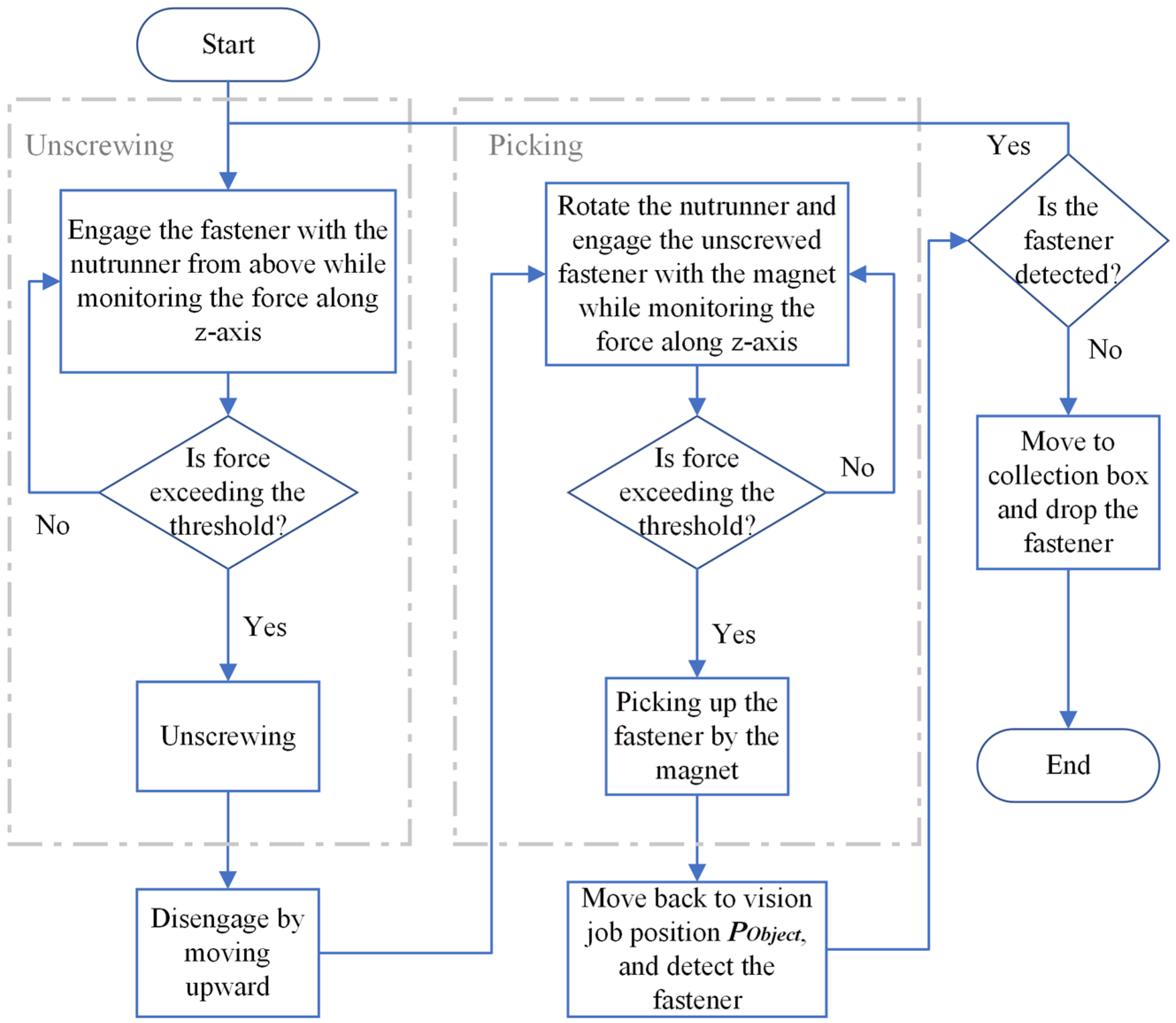
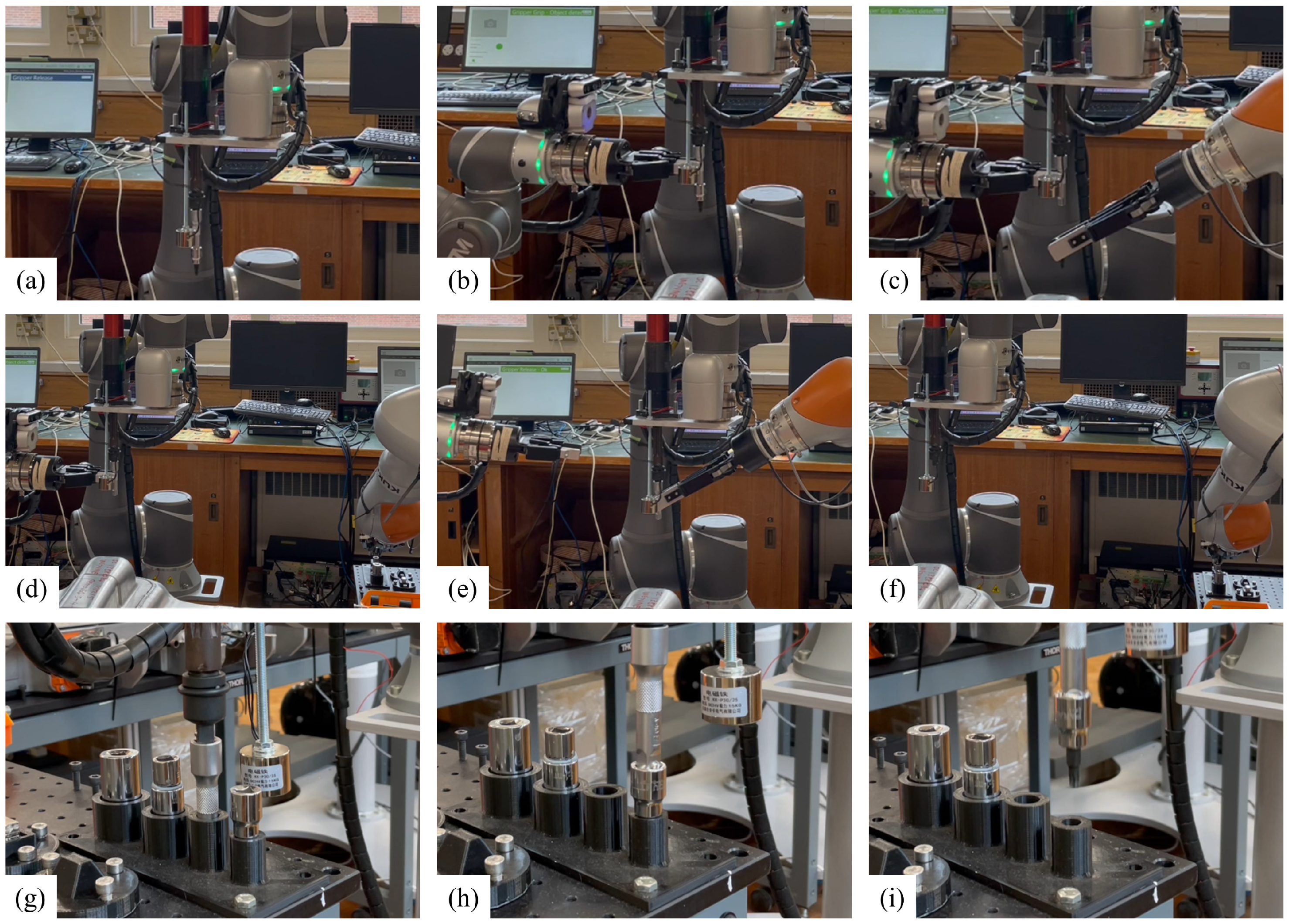
3.2.2. Unscrewing and Fastener Handling

Once the locations, P O b j e c t , of the screw heads or the nuts are obtained by the method mentioned above, the unscrewing and handling process can proceed following the workflow shown in Figure 7. It starts with moving the spindle frame, R S p i n d l e to P O b j e c t   ; then, it engages the fastener from above, while the force along the z-axis is constantly measured by the on-wrist force/torque sensor. Once the force threshold is exceeded, the robot stops moving downwards and starts the spindle. Then, the spindle is disengaged, and the electromagnet frame, R M a g n e t , is moved to P O b j e c t . The same process is repeated to pick up the loosened fasteners. Finally, the robot moves to the collection bin, switches off the electromagnet, and lets the fastener drop into the collection bin.
Sometimes, the loosened screws might be jammed at the thread, so the electromagnet cannot pick them up. Thus, each time after the picking process, the robot returns to P O b j e c t and detects whether the component is successfully picked up. If not, the whole unscrewing and picking process will be repeated, but the unscrewing time can be shortened to several seconds.

3.2.3. Multi-Robot-Collaborative Nutrunner Adapter Changing

Having a method to change the nutrunner adapters enables the robot to unscrew fasteners with different sizes, lengths, and shapes. As shown in Table 3, the adapters need to be changed frequently to various combinations, and both mounting and dismounting processes are involved. In this platform, the adapter-changing process is achieved by the collaboration of multiple robots. The proposed method does not require a sophisticated external device to achieve the dismantling process; instead, it takes advantage of having other robots equipped with grippers to complete the dismantling. The decision flow of the adapter-changing system is shown in Figure 8.
As shown in Figure 5c, the adapters are held upright in the adapter holder. When mounting the adapters, the robot aligns the nutrunner to the location above the adapter. Then, it turns on the spindle and slowly presses itself into the adapter. The whole process is monitored by the on-wrist F/T sensor to prevent excessive load on the robot. Once the adapter is fully attached to the spindle, the robot moves upwards for the next job position.

4. Results and Discussions

4.1. Validation of the Unscrewing System

Figure 9 shows some of the parts localised in this case study, including the landmark, 35 M5 × 10 mm screws connecting the top cover and the lower tray (Symbol A in Table 1), 14 nuts fixing the busbars/cables to the battery module terminals (Symbol I in Table 1), 14 terminal covers (Symbol H in Table), and 28 M6 × 95 mm bolts (Symbol L in Table 1). The parts can be successfully recognised with the matching scores, orientations, and numbers of found parts provided by the TM14’s operating system.
Figure 10 shows the unscrewing process discussed in Section 3.2 with an example of unscrewing an M5 screw on the top cover (step A in Table 1). Figure 11 shows the adapter-changing process described in Section 3.2.3.
A set of experiments is designed and performed to evaluate the performance of the proposed localisation method in terms of robustness against positional errors. As discussed in Section 3.2.1, the main purpose of using a vision system is to maintain a high success rate even when positional uncertainties are present in the disassembly processes. Regardless of the source of the error, all types of errors would change the robot’s starting location relative to the target object. Therefore, to mimic the relative positional errors between the robot and the objects, the robot is set to initialise the unscrewing operations with random starting locations, as indicated by the circles in Figure 6. Note that initialising the operation in an arbitrary space is equivalent to placing the target object randomly in a space of the same size.
Three methods of initialising the unscrewing operation are compared in this experiment. In Method 1, the robot initialises the unscrewing process from a fixed location and directly searches for the fasteners. In other words, the robot starts by localising the fasteners directly from a recorded position without any additional positional error to mimic an ideal situation. In Method 2, the robot initialises the operation from a random frame in a space that represents a relative positional error (as marked by S 1 in Figure 6), and it directly searches for the parts instead of using the proposed method described in Section 3.2.1 to first calibrate with the landmark. In Method 3, the robot starts the operation from a space the same size as in Method 2 (as marked by S 2 in Figure 6) and uses the proposed two-step localisation method to find the parts.
If the target object is found by any method, it starts the unfastening and picking process. The operation fails if the object is not found or picked up within three attempts. Each method is repeated 20 times by unfastening three different screws on the top cover (step A in Table 1) and one nut (step I in Table 1) on the battery module terminals. For comparison, the search range, patterns, and criteria are kept the same for all methods.
Initialising the operations from a random position is achieved by adding a uniformly generated noise to the initialisation frames of the operations. In other words, noise is added to V O b j e c t L M 0 for Method 2 and V L M 0 B a s e for Method 3. The range of the noise, which regulates the size of the random starting space, is set to be from 10 mm to + 10 mm for all translational axes and from 10 deg to + 10 deg for all rotational axes.
As shown in Figure 12, the unscrewing process starting with Method 3 achieved the same success rate as the one without introducing any additional positional errors within 80 repetitions, proving the effectiveness of the proposed method.

4.2. Comparison between Robotic and Human Disassembly

The whole disassembly process is demonstrated in Figure 13.
A comparison of the operation time between the human operators and the robot platform is made, as shown in Figure 14. The manual disassembly time is obtained by the average of three operators repeating the task at least six times. For robot operations in which the needed time is not fixed, such as the unscrewing operation, where multiple attempts might occur, the operation time is obtained by the average running time from ten repetitions.
For each of the operations, the human was faster than the robot. This is mainly because the platform developed at this stage only focuses on completing the operations instead of optimising them. Most of the operations were running at 20 to 30% of the maximum overall speed of the robots, which are 4 m/s and 2.5 m/s for TM14 and KUKA iiwa, respectively. The robotic operation time also depends on the speed of the nutrunner and the perception tasks, such as visually checking whether the fastener or the terminal cover has been removed. Thus, to increase the productivity of the platform, the limit of the operating speed needs to be tested, and the operations need to be optimised.
A remarkable speed difference can also be observed for step K—removing the high-voltage cables from the battery modules. This is because the high-voltage cables are flexible components, and their terminals are connected to the battery modules by threaded cylindrical connectors that might cause the terminals to become stuck on the connectors. This process involves a complex rule-based decision flow based on visual, force, and positional feedback, so it takes a remarkably long time compared with human operators. The same integration of all three kinds of information can be performed easily by human operators, who can remove the cable with both hands. Therefore, it is suggested that the manipulation of flexible components should be further developed as a crucial step to increase the platform’s efficiency.

4.3. Limitations of the Platform

The scope of this case study is to investigate non-destructive operations in EVB robotic disassembly. However, non-destructive operations alone cannot achieve complete autonomous pack-to-module disassembly. Thus, dismantling that is not easily achieved by non-destructive operations has been simplified in this case study and identified as evidence to guide future research.
First, cable ties have been widely used in EVB packs, as shown in Figure 15a. They are mainly used to secure the cables relative to the modules but are hard to remove non-destructively.
Second, as shown in Figure 15b, cable harnesses are also widely used to connect signalling cables. To remove the whole cable assembly, a robot needs to be able to disconnect snap-fitted harnesses, or the signalling cables need to be separated destructively from the harnesses via cutting.
Third, adhesive coolant pads placed between the modules and the lower tray of the battery pack, as shown in Figure 15c, have increased the force required when removing the modules from the pack. Since the force required is generally higher than the payload of the lightweight robots, the coolant pads are not considered in this case study.
Thus, more robotic disassembly tools are still required to solve these challenges and achieve a full autonomous pack-to-module disassembly for an EVB pack. Tool changer systems, as shown in Figure 3, can be used to maintain platform expandability by including more tools for the robots. Also, as the disassembly sequence is regulated by a central PC while the operations are stored locally in the robots’ controllers, the disassembly sequence of the platform can be reconfigured easily to maintain flexibility.

5. Conclusions

This paper proposes a robotic disassembly platform for dismantling a PHEV battery pack with seven modules consisting of prismatic cells. The platform focuses on non-destructive operations to obtain all seven battery modules from the pack. The battery pack disassembly plan, the platform architecture, and the disassembly processes have been proposed and validated. Design principles, such as using tool changers, the nutrunner adapter-changing method, and a central PC that regulates the disassembly sequence, are proposed to ensure the expandability and flexibility of the proposed platform.
Experimental results show that a two-step object localisation method based on 2D camera images improves the success rate of operations under positional uncertainties. Furthermore, a localisation method is integrated into the proposed unscrewing system that can (1) unscrew and handle threaded fasteners, (2) change the nutrunner adapters, (3) localise the fasteners under positional uncertainty, and (4) deal with situations in which the unfastened screws are jammed in holes.
The disassembly time was compared with that taken by human operators. Although humans are faster, automating the EV-LiB disassembly brings significant advantages from health, safety, and scalability perspectives. Also, note that the robots were only operating at 20 to 30% of their maximum overall speed, and the other design and operational decisions are also subject to further optimisation and development, such as improving the efficiency of manipulating cables and minimising idle time. Finally, limitations preventing the proposed platform from achieving a full autonomous pack-to-module disassembly, such as removing cable ties and disconnecting cable harnesses, are identified as promising future research directions.
There are a few more research topics for researchers to consider, apart from the future works mentioned above. Firstly, since this paper did not consider some extreme EoL conditions for the EVBs, such as broken bolts and severe deformation, improvements in that aspect are encouraged to be considered. Secondly, since the proposed platform targets only one model of battery pack, expanding the number of models the platform can dismantle should also be investigated. Finally, the economic feasibility of disassembly automation can be analysed from socio-economic and commercial perspectives.

Author Contributions

Conceptualization, M.Q., D.T.P., F.A., A.G., M.K., F.L., M.M. and S.X.; methodology, M.Q., F.A., A.G., M.M. and S.X.; software, M.Q., F.A., A.G., K.J., F.L., M.M. and S.X.; validation, M.Q., F.A., A.G., F.L., M.M. and S.X.; formal analysis, M.Q., F.A., A.G., N.H., K.J. and S.X.; investigation, M.Q., F.A., A.G., K.J., F.L., M.M. and S.X.; resources, D.T.P., M.K. and Y.W.; data curation, M.Q. and K.J.; writing—original draft preparation, M.Q.; writing—review and editing, M.Q., D.T.P., K.J. and Y.W.; visualization, M.Q., N.H. and K.J.; supervision, M.Q., D.T.P. and Y.W.; project administration, M.Q., D.T.P. and Y.W.; funding acquisition, D.T.P. and Y.W. All authors have read and agreed to the published version of the manuscript.

Funding

This work was supported by the Engineering and Physical Sciences Research Council (EPSRC) [grant numbers EP/N018524/1 and EP/W00206X/1] and the Jiangsu Industrial Technology Research Institute (JITRI) [grant title: Hierarchical Use Of Battery: Intelligent Evaluation And Collaborative Robot Disassembly].

Data Availability Statement

The raw data supporting the conclusions of this article will be made available by the authors on request.

Acknowledgments

We would like to express our gratitude to Jaguar Land Rover for its generous donation of the electric vehicle battery used in this research. Special thanks are due to Andrew Brown for his invaluable support and assistance in facilitating the acquisition of the electric vehicle battery.

Conflicts of Interest

The authors declare no conflict of interest.

References

  1. IEA. Global EV Data Explorer. Available online: https://www.iea.org/data-and-statistics/data-tools/global-ev-data-explorer (accessed on 7 November 2023).
  2. Fan, E.; Li, L.; Wang, Z.; Lin, J.; Huang, Y.; Yao, Y.; Chen, R.; Wu, F. Sustainable Recycling Technology for Li-Ion Batteries and Beyond: Challenges and Future Prospects. Chem. Rev. 2020, 120, 7020–7063. [Google Scholar] [CrossRef] [PubMed]
  3. Harper, G.; Sommerville, R.; Kendrick, E.; Driscoll, L.; Slater, P.; Stolkin, R.; Walton, A.; Christensen, P.; Heidrich, O.; Lambert, S.; et al. Recycling lithium-ion batteries from electric vehicles. Nature 2019, 575, 75–86. [Google Scholar] [CrossRef] [PubMed]
  4. Kampker, A.; Wessel, S.; Fiedler, F.; Maltoni, F. Battery pack remanufacturing process up to cell level with sorting and repurposing of battery cells. J. Remanufacturing 2021, 11, 1–23. [Google Scholar] [CrossRef]
  5. Meng, K.; Xu, G.; Peng, X.; Youcef-Toumi, K.; Li, J. Intelligent disassembly of electric-vehicle batteries: A forward-looking overview. Resour. Conserv. Recycl. 2022, 182, 106207. [Google Scholar] [CrossRef]
  6. Thompson, D.; Hyde, C.; Hartley, J.M.; Abbott, A.P.; Anderson, P.A.; Harper, G.D. To shred or not to shred: A comparative techno-economic assessment of lithiumion battery hydrometallurgical recycling retaining value and improving circularity in LIB supply chains. Resour. Conserv. Recycl. 2021, 175, 105741. [Google Scholar] [CrossRef]
  7. Lai, X.; Huang, Y.; Deng, C.; Gu, H.; Han, X.; Zheng, Y.; Ouyang, M. Sorting, regrouping, and echelon utilization of the large-scale retired lithium batteries: A critical review. Renew. Sustain. Energy Rev. 2021, 146, 111162. [Google Scholar] [CrossRef]
  8. Vongbunyong, S.; Chen, W.H. Disassembly Automation: Automated Systems with Cognitive Abilitie; Springer: Cham, Switzerland, 2015. [Google Scholar]
  9. Poschmann, H.; Brüggemann, H.; Goldmann, D. Disassembly 4.0: A Review on Using Robotics in Disassembly Tasks as a Way of Automation. Chem. Ing. Tech. 2020, 92, 341–359. [Google Scholar] [CrossRef]
  10. Lee, M.-L.; Liu, W.; Behdad, S.; Liang, X.; Zheng, M. Robot-Assisted Disassembly Sequence Planning with Real-Time Human Motion Prediction. IEEE Trans. Syst. Man, Cybern. Syst. 2022, 53, 438–450. [Google Scholar] [CrossRef]
  11. Qu, M.; Wang, Y.; Pham, D.T. Robotic Disassembly Task Training and Skill Transfer Using Reinforcement Learning. IEEE Trans. Ind. Informatics 2023, 19, 10934–10943. [Google Scholar] [CrossRef]
  12. Li, R.; Ji, C.; Liu, Q.; Zhou, Z.; Pham, D.T.; Huang, J.; Tan, Y.; Qu, M.; Wang, Y.; Kerin, M.; et al. Unfastening of Hexagonal Headed Screws by a Collaborative Robot. IEEE Trans. Autom. Sci. Eng. 2020, 17, 1–14. [Google Scholar] [CrossRef]
  13. Chen, W.H.; Foo, G.; Kara, S.; Pagnucco, M. Automated generation and execution of disassembly actions. Robot. Comput. Manuf. 2021, 68, 102056. [Google Scholar] [CrossRef]
  14. Huang, J.; Pham, D.T.; Li, R.; Qu, M.; Wang, Y.; Kerin, M.; Su, S.; Ji, C.; Mahomed, O.; Khalil, R.; et al. An experimental human-robot collaborative disassembly cell. Comput. Ind. Eng. 2021, 155, 107189. [Google Scholar] [CrossRef]
  15. Huang, J.; Pham, D.T.; Wang, Y.; Qu, M.; Ji, C.; Su, S.; Xu, W.; Liu, Q.; Zhou, Z. A case study in human–robot collaboration in the disassembly of press-fitted components. Proc. Inst. Mech. Eng. Part B J. Eng. Manuf. 2019, 234, 654–664. [Google Scholar] [CrossRef]
  16. Yu, J.; Zhang, H.; Jiang, Z.; Yan, W.; Wang, Y.; Zhou, Q. Disassembly task planning for end-of-life automotive traction batteries based on ontology and partial destructive rules. J. Manuf. Syst. 2022, 62, 347–366. [Google Scholar] [CrossRef]
  17. Wu, T.; Zhang, Z.; Yin, T.; Zhang, Y. Multi-objective optimisation for cell-level disassembly of waste power battery modules in human-machine hybrid mode. Waste Manag. 2022, 144, 513–526. [Google Scholar] [CrossRef] [PubMed]
  18. Alfaro-Algaba, M.; Ramirez, F.J. Techno-economic and environmental disassembly planning of lithium-ion electric vehicle battery packs for remanufacturing. Resour. Conserv. Recycl. 2020, 154, 104461. [Google Scholar] [CrossRef]
  19. Wu, T.; Zhang, Z.; Zeng, Y.; Zhang, Y.; Guo, L.; Liu, J. Techno-economic and environmental benefits-oriented human–robot collaborative disassembly line balancing optimization in remanufacturing. Robot. Comput. Manuf. 2024, 86, 102650. [Google Scholar] [CrossRef]
  20. Hellmuth, J.F.; DiFilippo, N.M.; Jouaneh, M.K. Assessment of the automation potential of electric vehicle battery disassembly. J. Manuf. Syst. 2021, 59, 398–412. [Google Scholar] [CrossRef]
  21. Wegener, K.; Chen, W.H.; Dietrich, F.; Dröder, K.; Kara, S. Robot Assisted Disassembly for the Recycling of Electric Vehicle Batteries. Procedia CIRP 2015, 29, 716–721. [Google Scholar] [CrossRef]
  22. Fleischer, J.; Gerlitz, E.; Rieβ, S.; Coutandin, S.; Hofmann, J. Concepts and Requirements for Flexible Disassembly Systems for Drive Train Components of Electric Vehicles. Procedia CIRP 2021, 98, 577–582. [Google Scholar] [CrossRef]
  23. Poschmann, H.; Brüggemann, H.; Goldmann, D. Fostering End-of-Life Utilization by Information-driven Robotic Disassembly. Procedia CIRP 2021, 98, 282–287. [Google Scholar] [CrossRef]
  24. Tan, W.J.; Chin, C.M.M.; Garg, A.; Gao, L. A hybrid disassembly framework for disassembly of electric vehicle batteries. Int. J. Energy Res. 2021, 45, 8073–8082. [Google Scholar] [CrossRef]
  25. Wegener, K.; Andrew, S.; Raatz, A.; Dröder, K.; Herrmann, C. Disassembly of Electric Vehicle Batteries Using the Example of the Audi Q5 Hybrid System. Procedia CIRP 2014, 23, 155–160. [Google Scholar] [CrossRef]
  26. Hjorth, S.; Chrysostomou, D. Human–robot collaboration in industrial environments: A literature review on non-destructive disassembly. Robot. Comput. Manuf. 2022, 73, 102208. [Google Scholar] [CrossRef]
  27. Chen, W.H.; Wegener, K.; Dietrich, F. A robot assistant for unscrewing in hybrid human-robot disassembly. In Proceedings of the 2014 IEEE International Conference on Robotics and Biomimetics (ROBIO 2014), Bali, Indonesia, 5–10 December 2014; pp. 536–541. [Google Scholar]
  28. Zhou, L.; Zhang, L.; Konz, N. Computer Vision Techniques in Manufacturing. IEEE Trans. Syst. Man, Cybern. Syst. 2022, 53, 105–117. [Google Scholar] [CrossRef]
  29. Li, H.; Zhang, H.; Zhang, Y.; Zhang, S.; Peng, Y.; Wang, Z.; Song, H.; Chen, M. An Accurate Activate Screw Detection Method for Automatic Electric Vehicle Battery Disassembly. Batteries 2023, 9, 187. [Google Scholar] [CrossRef]
  30. Zorn, M.; Ionescu, C.; Klohs, D.; Zähl, K.; Kisseler, N.; Daldrup, A.; Hams, S.; Zheng, Y.; Offermanns, C.; Flamme, S.; et al. An Approach for Automated Disassembly of Lithium-Ion Battery Packs and High-Quality Recycling Using Computer Vision, Labeling, and Material Characterization. Recycling 2022, 7, 48. [Google Scholar] [CrossRef]
Figure 1. Inner structure of the dummy PEEV-LiB pack. The fourth battery module is located underneath the junction box. All battery modules are replaced by dummies for safety reasons.
Automation 05 00005 g001
Figure 2. The PHEV-LiB disassembly sequence developed for this case study. The sequence is generated based on the intuitive steps used to disassemble the pack. It can also be observed that most of the repetitive operations involve unscrewing.
Automation 05 00005 g002
Figure 3. (a) Photo and (b) simulation model of the proposed four-robot disassembly platform in operation. The cell deploys four lightweight industrial robots, and they are located on each side of the battery pack to ensure accessibility. In this case study, two KUKA iiwa lbr 14 robots are used as Robots A and B, and two Techman TM14 robots are used as Robots C and D. The simulation model is built with the RoboDK software (version 5.2.5).
Automation 05 00005 g003aAutomation 05 00005 g003b
Figure 4. An in-house-built vacuum gripper attached to Robot A, as shown in (a) a photo and (b) a CAD model. The vacuum gripper is used to handle bulky components, such as the battery modules, which cannot be handled by commonly seen electrical grippers.
Automation 05 00005 g004
Figure 5. The nutrunner system, which consists of (a) the electric nutrunner equipped on Robot C and (b) nutrunner adapters; from left to right: an extension bar, an M6 Torx socket, a 3/8 inch gripper socket, a 1/4 inch gripper socket, and (c) an adapter holder.
Automation 05 00005 g005
Figure 6. Information about the robotic unscrewing operation. Frame is a term describing the 6-dimensional position information (translation and rotation) of any spatial point in a robotic system. In this system, the spindle and the electromagnet are fixed to the robot flange connected to the robot base, and the relative distances between their frames to the flange frame are used to compute the robot joint movements based on inverse kinematics. Vision frames are locations for the robot flange to initialise the localisation processes. The dashed straight lines indicate the relative positions of different parts of the system. To assist in describing the experiment mentioned in Section 4.1, the dashed circles indicate spaces where the localisation jobs could initialise to mimic the positional errors. Note that initialising the operation in a random space is equivalent to placing the target object randomly in a space of the same size since localisation aims to obtain a relative displacement between the vision frame and the target object. Additionally, note that the sizes of the circles do not reflect the actual sizes of the random spaces. However, this indicates that the two spaces are the same size.
Automation 05 00005 g006
Figure 7. Flow chart of the unscrewing and picking process.
Automation 05 00005 g007
Figure 8. Decision flow of the adapter-changing system.
Automation 05 00005 g008
Figure 9. Demonstration of parts being recognised and localised (a) in reality and (b) by the embedded on-wrist camera of the TM14 robot and its operating system, TMflow. The arrows represent the 2D orientations relative to the vision job frames. The numbers outside the brackets are the matching scores compared with the training images in percentage, and the integers inside the brackets denote how many objects have been detected. To avoid unexpected movements, each vision job is limited to recognising just one component by limiting the search range inside of the image.
Automation 05 00005 g009
Figure 10. Demonstration of the whole unscrewing process in the following steps: (a) calibration with the landmark, (b) opening the camera to localise the fastener, (c) translating the nutrunner over the fastener, (d) engaging with the nutrunner until reaching a force threshold, (e) unscrewing, (f) translating the electromagnet over the fastener, (g) engaging with the electromagnet until reaching a force threshold, (h) opening the camera and making sure the fastener is successfully picked up, (i) moving to the collection bin, and (j) turning off the electromagnet to release the fastener.
Automation 05 00005 g010
Figure 11. Demonstration of the three-robot-collaboration adapter-changing process in the following steps: (a) Robot C moving to a changing position, (b) Robot D gripping the extension adapter, (c) Robot B removing the Torx head adapter, (d) Robot B placing the Torx head adapter in the adapter holder, (e) Robot D releasing the gripping and Robot B gripping the extension adapter, (f) Robot B placing the extension adapter into the adapter holder, (g) Robot C mounting the extension adapter, (h) Robot C mounting the next adapter, and (i) moving to the next operation.
Automation 05 00005 g011
Figure 12. Comparison of the unscrewing success rates when initialising with three localisation methods. Blue blocks indicate successful unscrewing operations with different numbers of attempts. If the localisation process does not find the part or the robot fails to pick up the component within three attempts, it is labelled a failure.
Automation 05 00005 g012
Figure 13. Demonstration of the whole robotic disassembly process in the sequence and subfigure symbols corresponding to Figure 2 and Table 1.
Automation 05 00005 g013
Figure 14. Comparison of each disassembly operation between the human operators and the robot platform. The operation time of the human operators starts to count down when the operator has fully equipped the correct tool and begins to engage the parts, and it ends when the operator places the dismantled parts in the designated collection bins. In other words, the time to change tools and to move around the working area is not counted. The robot operation time is measured in the same way.
Automation 05 00005 g014
Figure 15. Examples of challenges for robotic disassembly operations identified in this case study. (a) Example locations and detailed view of the cable ties. They are mainly used to secure the middle sections of the signalling cables to the battery modules. To remove the signalling cables, they need to be removed first. (b) Example usage of cable harnesses in the battery pack. The cable harnesses need to be disconnected to remove the signalling cables by the robots. (c) Coolant pads between the battery modules and the pack are used for heat dissipation and damping. However, they increase the adhesion between the module and the lower tray, resulting in a large separation force. The red boxes focus attention on the cable ties in (a), the cable harnesses in (b) and the cooling pads in (c).
Automation 05 00005 g015
Table 1. Components removed or disconnected at each stage.
Disassembly StagesDisassembly Step Symbols
(cf. Figure 2)
Disassembly ProcessRepetitionComponent Removed or Disconnected
Stage 1: Top cover removalAUnscrewing35M5 × 10 mm screw
BRemoval1Top cover
Stage 2: Circuit breakingCRemoval1L-shape cover
DUnscrewing1M6 nut
EDisconnection1High-voltage cable
Stage 3: Junction box removalFUnscrewing4M6 × 16 mm bolt
GRemoval1Junction box
Stage 4: Battery module removalHRemoval14Terminal cover
IUnscrewing14Nuts
JRemoval5Busbar
KRemoval3High-voltage cable
LUnscrewing28M6 × 95 mm bolt
MRemoval7Battery module
Table 2. Main end-effectors and duties allocated for each Robot.
RobotMain End-EffectorsMain Duty
Robot AVacuum gripperHandling bulky objects
Robot BTwo-finger gripperHandling small objects
Robot CNutrunnerUnscrewing
Robot DTwo-finger gripperHandling small objects
Table 3. Fasteners being unscrewed and the corresponding adapters.
Disassembly StepFastener TypeSizeHead TypeUsed AdapterWith ExtensionRepetitions
AScrewM5 × 10 mmHexagonal3/8-inch gripper socketNo35
DNutM6Hexagonal1/4-inch gripper socketNo1
FScrewM6 × 16 mmHexagonal1/4-inch gripper socketYes4
INutM6Hexagonal1/4-inch gripper socketNo14
LScrewM6 × 95 mmTorxM6 Torx-shape socketYes28
Note: The nuts unscrewed and adapters used are identical in disassembly steps D and I. They are listed twice because the nutrunner needs to change adapters for another operation in between.
Disclaimer/Publisher’s Note: The statements, opinions and data contained in all publications are solely those of the individual author(s) and contributor(s) and not of MDPI and/or the editor(s). MDPI and/or the editor(s) disclaim responsibility for any injury to people or property resulting from any ideas, methods, instructions or products referred to in the content.

