Article

Colored 3D Path Extraction Based on Depth-RGB Sensor for Welding Robot Trajectory Generation

by
Alfonso Gómez-Espinosa
*,
Jesús B. Rodríguez-Suárez
,
Enrique Cuan-Urquizo
,
Jesús Arturo Escobedo Cabello
and
Rick L. Swenson
Tecnologico de Monterrey, Escuela de Ingenieria y Ciencias, Querétaro 76130, Mexico
*
Author to whom correspondence should be addressed.
Automation 2021, 2(4), 252-265; https://doi.org/10.3390/automation2040016
Submission received: 13 September 2021 / Revised: 27 October 2021 / Accepted: 4 November 2021 / Published: 5 November 2021
(This article belongs to the Special Issue Networked Predictive Control for Complex Systems)

Abstract

:
The necessity for intelligent welding robots that meet the demand in real industrial production, according to the objectives of Industry 4.0, has been supported owing to the rapid development of computer vision and the use of new technologies. To improve the efficiency in weld location for industrial robots, this work focuses on trajectory extraction based on color features identification on three-dimensional surfaces acquired with a depth-RGB sensor. The system is planned to be used with a low-cost Intel RealSense D435 sensor for the reconstruction of 3D models based on stereo vision and the built-in color sensor to quickly identify the objective trajectory, since the parts to be welded are previously marked with different colors, indicating the locations of the welding trajectories to be followed. This work focuses on 3D color segmentation with which the points of the target trajectory are segmented by color thresholds in HSV color space and a spline cubic interpolation algorithm is implemented to obtain a smooth trajectory. Experimental results have shown that the RMSE error for V-type butt joint path extraction was under 1.1 mm and below 0.6 mm for a straight butt joint; in addition, the system seems to be suitable for welding beads of various shapes.

1. Introduction

In the era of globalization, manufacturing industries deal with competitive and uncertain markets, where the dynamics of innovations and shortened life cycles products create a problem for the industry to become more productive and flexible; for instance, welding processes are one of the most common tasks in manufacturing industries, and robots equipped with intelligent programming tools represent the best alternatives to achieve these goals [1].
Nowadays, there are two main categories of robotic programming methods in industrial applications, as well as online and offline programming [2]; however, the time spent programming a new path for a job in high-volume manufacturing industries becomes the main challenge of using welding robots, especially when changes and uncertainties to the geometric shape in products occur, which is why robotic systems based on intelligence and robotic perception are one of the four pillars of research and implementation according to ”Industry 4.0” objectives [3].
A computer vision system is required to capture the surfaces or features and help achieve fast offline programming [2]. However, the obstacle toward achieving an intelligent welding robot is solving the problem of trajectory planning, seam tracking, and the control of welding systems against errors caused by light and environment disturbances to which each vision system is exposed [4].
For example, as regards simple systems using only a single camera as a sensor, Kiddee et al. [5] develop a technique to find a T-welding seem based on image processing to smooth the image and extract the edges of the image by using a canny algorithm, to find the initial and endpoints. In the same way, Ye et al. [6] acquire the edges of a series of images to determine the location of the weld seam using a series of known characteristics. Yang et al. [7] present a welding detection system based on 3D reconstruction technology for the arc welding robot. The shape from the shading SFS algorithm is used to reconstruct the 3D shapes of the welding seam.
Laser vision systems are among the most widely used sensors in welding robotics due to the precision and fast data processing that these devices provide. In particular, laser sensors are mostly applied in weld tracking research, where they have been developed since simple systems such as the one by Fernandez et al. [8] that implements a low-cost laser vision system based on a webcam on the robot arm oriented toward the laser stripe projected at a 45° angle, up to systems already proved in the industrial context, for example, the study by Liu et al. [9], in which an autonomous method is proposed to find the initial weld position for a fillet weld seam formed by two steel plates. This method employs an automatic dynamic programming-based laser light inflection point extraction algorithm. The algorithm for this method can support factors induced by natural light that may be present during the processing of laser vision images.
Disturbances in laser systems on metallic surfaces are a common problem in weld bead localization. Li et al. [10] suggest reducing the influence of noise on the extraction of the centerline, through the double-threshold recursive least square method. Later, an automatic welding seam recognition and tracking method by utilizing structured light vision to search through a Kalman filter the profile of the welding seam in a small area, aiming to avoid some disturbances [10]. Another approach in structured light systems incorporated an optical filter and LED lighting developed to reduce the effect of noise produced by the arc torch. Where a fuzzy-PID controller can be used to obtain the weld seam in horizontal and vertical directions simultaneously [11].
Recent systems tend to be more robust or complex in terms of the number of tools involved in obtaining images, filtering data. For example, Zeng et al. [12] propose a weld position recognition method based on directional light and structured light information fusion during multi-layer/multi-pass welding. On other hand, Guo et al. [13] present a multifunctional monocular visual sensor based on combined laser structured lights, which has the functions such as the detection of the welding groove cross-sectional parameters, application for the joint tracking, the detection of the welding torch height, the measuring of the weld bead appearance, and the monitoring of welding process in real time. Other approaches for real-time processing are described by Kos et al. [14] to compute the position of the laser beam and the seam in 3D during welding with a camera and illumination laser in order to equalize the brightness of the keyhole and the surrounding area. Zhang et al. [15] acquire the 3D information by multiple segment laser scanning. The weld features are extracted by cubic smoothing spline, to detect the characteristic parameters of weld lap joint with a deviation lower than 0.4 mm.
Another research topic in robotic vision is systems that acquire images from two optical devices. In this sense, Chen et al. [16] propose a Canny detector, where the two parallel edges captured in a butt v-joint are used to fitting the value of the start welding position. In a similar way, Dinham et al. [17] use a Hough transform to detect the outside boundary of the weldment so that the background can be removed. In weld tracking systems, Ma et al. [18] use two normal charge-coupled device cameras to capture clear images from two directions—one is used to measure the root gap, and the other is used to measure the geometric parameters of the weld pool.
Nowadays, owing to the precision of sensors and to have a complete understanding of the environment, 3D reconstruction techniques have been explored. In reconstruction with laser systems, 3D point cloud data are used to reconstruct welding seam, through the point cloud and guided by a neural network proposed by Xiao et al. [19], which can obtain the equations and initial points of the weld seam. The test results of the guidance prove that the extraction error is less than 0.6 mm, meeting actual production demand.
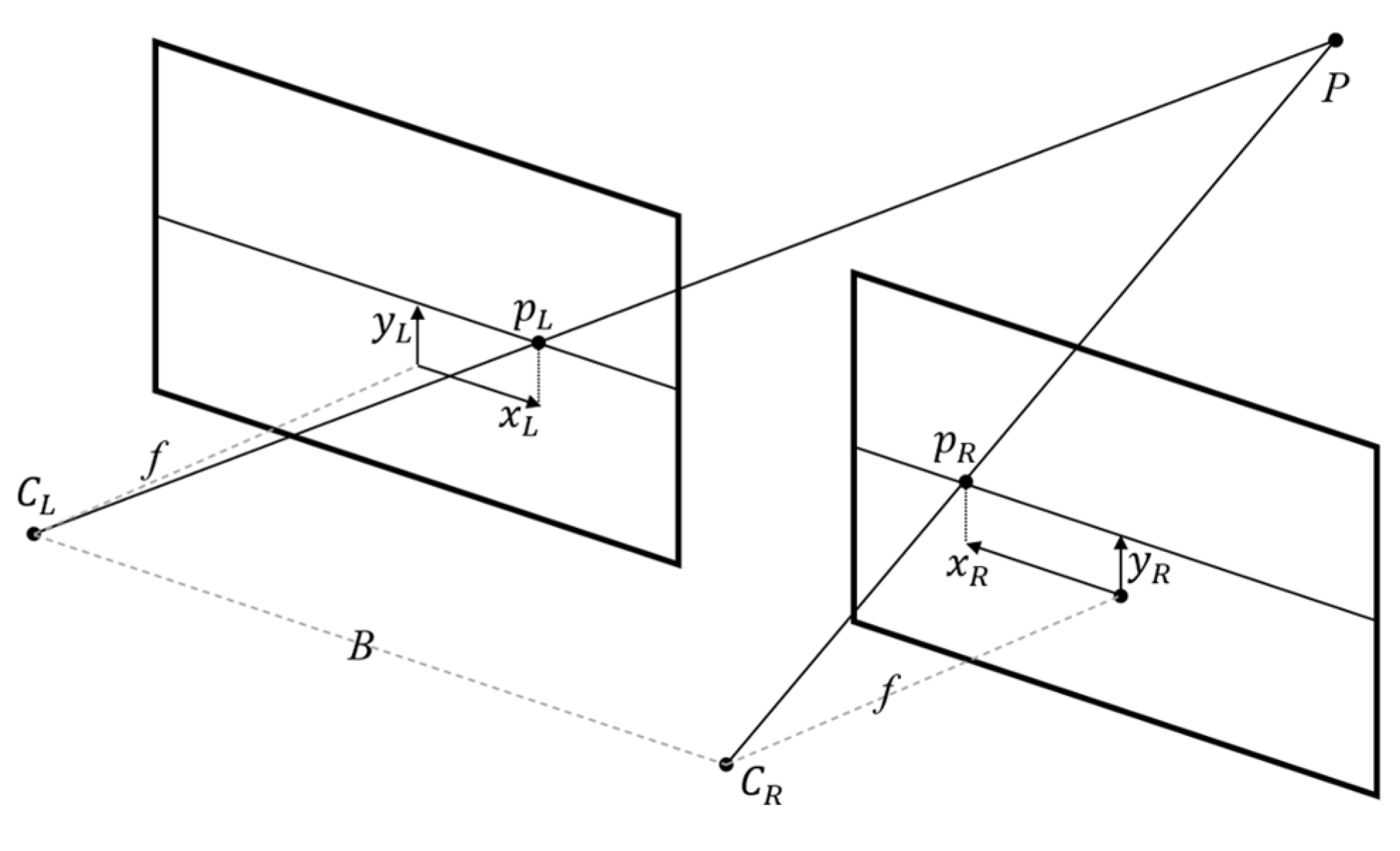
In stereo vision, Yang et al. [20] propose a 3D path teaching method to improve the efficiency of teaching playback based on a stereo-structured light vision system using a seam extraction algorithm, which could achieve fast and accurate seam extraction to modify the model of the weld seam. Their system could well realize a fast and accurate 3D path teaching of a welding robot. Experiment results show a measurement resolution less than 0.7 mm and are suitable for V-type butt joint before welding [21]. In point clouds acquired with RGB-D sensors, Maiolino et al. [22] use an ASUS Xtion sensor to register and integrate the point cloud with the CAD model to perform an offline programming system for sealant dispensing robot. On the other hand, Zhou et al. [23] use an Intel family camera to detect and generate the trajectory with an algorithm based on the gradient of the edge intensity in the point cloud. However, the main limitation of the proposals found in the literature is that they seek to find a solution to a particular type of weld seam. Global path extraction systems are in the process of development; therefore, we find that the integration of color and segmentation of these data have not been the subject of research in welding robotics as a global acquisition system.
In this work, a color point cloud segmentation method was implemented to extract 3D paths for robot trajectory generation. The developed system consists of a RealSense D435 sensor, a low-cost device that incorporates technologies such as stereo vision and RGB sensor, with which the 3D reconstruction of a point cloud that incorporates the color of the work object, with this color information a series of filters are applied in the HSV color space to segment the region of interest where the weld bead is expected to be applied. Once captured the zone, a spline cubic interpolation is executed to calculate the path that smoothest the trajectory of the welding points that would require a robotic manipulator.
The rest of this paper is organized as follows: Section 2 describes the theory related to vision systems and algorithms to perform our 3D reconstruction processing seam extraction. Section 3 introduces the configuration of our experiment platform and vision sensor, and the results are presented in Section 4. Finally, in Section 5, concluding remarks are provided.

2. Materials and Methods

2.1. Stereo Vision

Arrangements that consist of two image sensors (cameras) separated by a known distance are known as stereo systems. The principle of stereoscopy is based on the ability of the human brain to estimate the depth of objects present in the images captured by eyes [24]. In the stereoscopic configuration, two cameras are placed close to each other with parallel optical axes. Both cameras, with centers CL and CR separated by a distance B, called the baseline, have the same focal length f so that the left and right images are in parallel planes. A point in the three-dimensional space P will be projected in different positions, pL and pR with coordinates (xL, yL) and (xR, yR), respectively, of the planes of the images because it is seen from slightly different angles. This difference in position is known as disparity and is mathematically described as disparity = xL − xR and is used to calculate the z distance in (1) through the geometric relationship [25], as shown in Figure 1.
z = B   × f disparity

2.2. Structured Light

Structured light is an active method to improve depth acquisition by using an external light source that provides additional information to the system. Structured light is based on the use of active illumination of the scene with a specially designed 2D spatially varying intensity pattern, where the camera sensor searches for artificially projected features that serve as additional information for triangulation [26]. In the present work proposal, the RealSense sensor has an optical projector that uses a pseudo-random binary array to produce a grid-indexing strategy of dots. The array is defined by an n1 × n2 array encoded using a pseudo-random sequence, such that every k1 by k2 sub-window over the entire array is unique [27].

2.3. Point Cloud

Depth cameras deliver depth images, in other words, images whose intensity values represent the depth of the point (x, y) in the scene. A point cloud is a data structure used to represent points with three dimensions (X, Y, Z), where the depth is represented by the Z coordinate [28]. Once the depth images are available, it is possible to obtain the point cloud using the intrinsic values of the camera with which the information was acquired. This process is known as deprojection; a point P with coordinates (X, Y, Z) can be obtained according to (2, 3, 4) from the depth information Dx,y being (x, y) the rectified position of the pixel in the sensor, where the variables cx, cy, fx, and fy are the intrinsic values of the camera used to acquire the information, with (fx, fy) as the components of the focal length and (cx, cy) the image projection center [29].
X = D x , y ( C x x ) f x
Y = D x , y ( C y y ) f y
Z = D x , y .  

2.4. Colored Point Cloud

Some 3D sensors are often coupled to an RGB camera, with which research on color depth registration is being carried out. Registering two cameras means knowing the relative position and orientation of one scene with respect to another [30]. In principle, color integration consists of reprojecting each 3D point onto the RGB image to adopt its color. When reprojected in 3D, the generated point cloud contains six information fields—three for spatial coordinates and three with color values. However, due to occlusion, not all reconstructed 3D points in the scene are visible from the RGB camera, so some points may lack color information [31]. Figure 2 shows the result of the colorization of the point cloud.

3. Experimental Setup

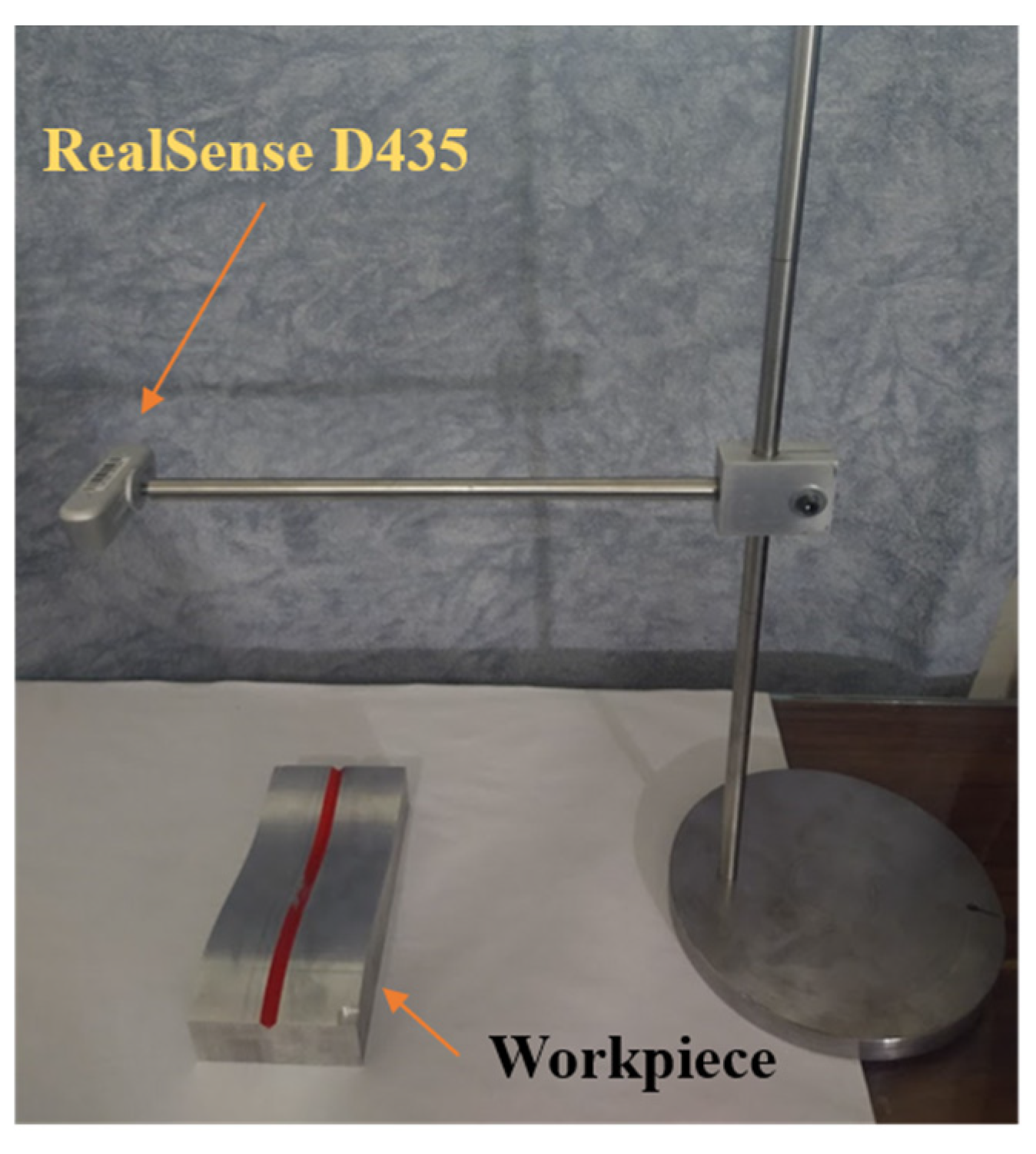
The integrated vision system incorporates an RGB-D camera (Intel RealSense D435), an active stereo depth camera to compute the stereo depth data for real time. It also has an optional infrared (IR) projector that assists in improving depth accuracy. The sensor is physically supported on a test arm that will allow an image acquisition from a top view of the work object at a distance ranging from 30 to 70 cm over the welding work zone, as shown in Figure 3.
The proposed robotic system consists of an RGB-D camera that captures the surface point cloud of the workpiece, the welding seam detection algorithm that locates the color seam region in the input point cloud, and the trajectory generation method that processes the point set and outputs a 3D welding trajectory.
The image acquisition and trajectory planning algorithms implementation were carried out on a personal computer with the Windows 10 operating system and operating with an Intel i7 CPU @ 2.40 GHz, with the necessary USB 3.0 ports required for the communication with the RealSense D435 camera.

3.1. Test Sample

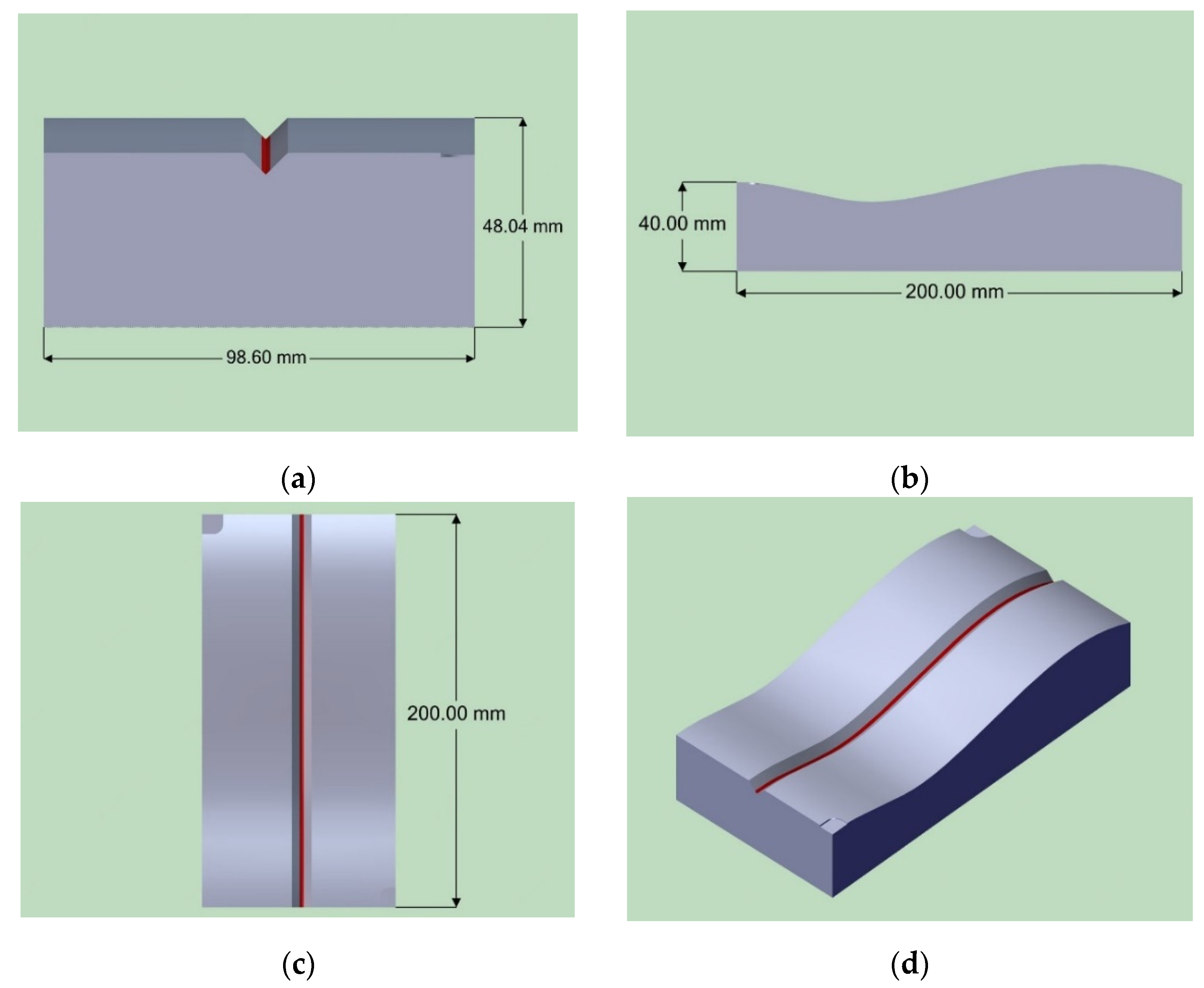
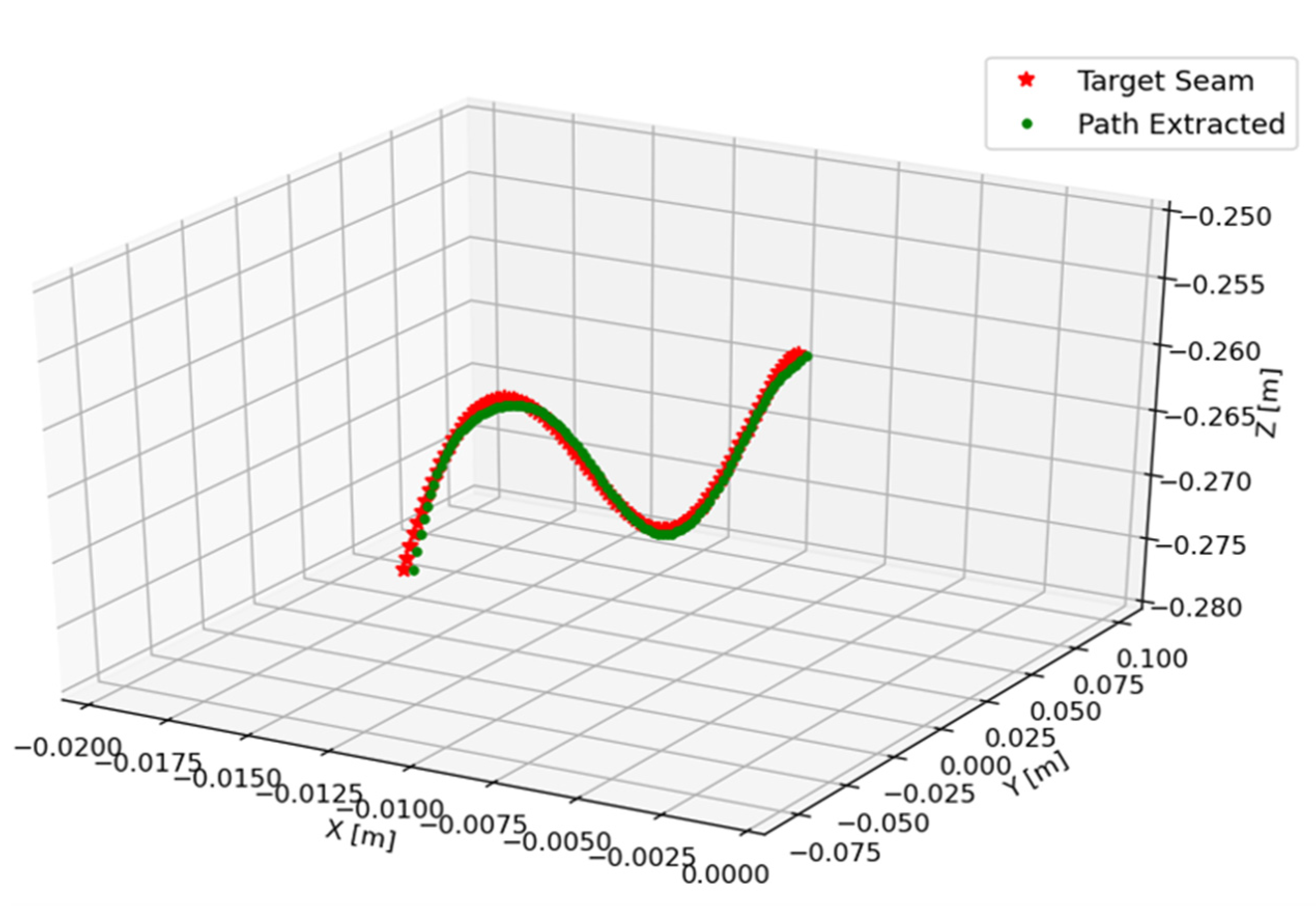
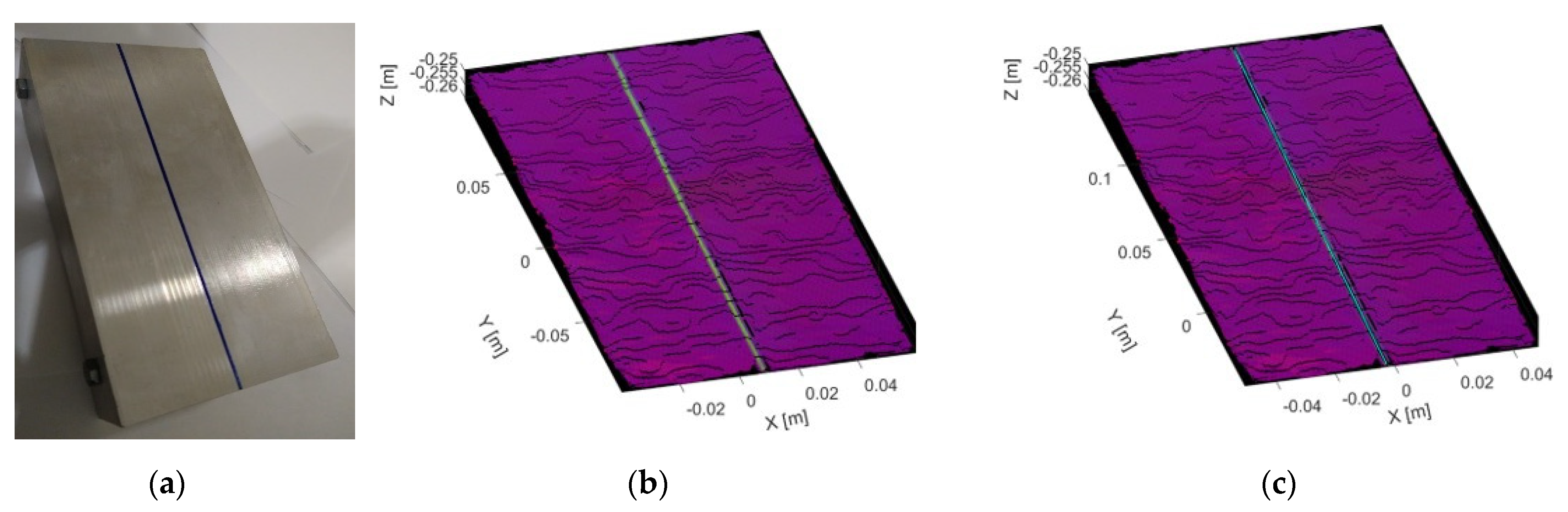
A test object was designed so that the geometric characteristics of the part could be mathematically parametrized. It consists of two parts designed both as a semi-complex surface with curvature as well as to simulate a V-type welded joint, one of the most investigated in the literature, with a depth of 5 mm and an angular opening of 90°. The assembly of these two pieces results in a test piece of 20 × 10 cm having 4.8 cm at its highest part.
The CAD models of Figure 4 show the design of the test piece that was fabricated in aluminum 6061 T6, considering that aluminum is a highly moldable and reflective material, which could serve as a parameter to measuring light disturbances in the vision system. It is important to note that the sample part was machined with tungsten carbide milling tools whose toolpaths were programmed in WorkNC CAM software; the machining parameters are listed in Table 1. The machining was performed on a HAAS VF3 CNC machine, to match the part to the CAD model, because machines such as these report positioning errors below 0.05 mm.

3.2. Trajectory Extraction Based on Stereo Vision System Embedding Color Data

Figure 5 shows the steps necessary for the definition of parameters and processing of the images that will carry out the extraction of the points corresponding to the weld bead. Next, the objective of each block was defined.
Set up the data acquisition parameters: Image acquisition and processing was performed by Intel SDK [32], which, as an open source software program, has support for different programming languages, such as python, through the pyrealsense2 library, the official python wrapper. Since the implemented vision system has different sensors, both color and depth sensors were set to a resolution of 640 × 480 pixels and a frame rate of 30 fps, with a depth accuracy between 0.1 to 1 mm.
Acquire and align depth and color frame information: It is necessary to align the depth and color frames to make a 3D reconstruction faithful to the captured scene. This was achieved through the pyrealsense2 library [32], which has an algorithm that aligns the depth image with another image, in this case, the color image.
Segment and remove the background data: Sometimes, we seek to process a region of interest (ROI); in this case, the ROI is defined by the distance at which the test object is located relative to the camera. Therefore, we first planned a filter using one of the device’s own tools to acquire the images [32], where a depth clipping distance in which all information beyond our ROI was segmented and removed instead of using all the information in the scene.
Point-cloud calculation from depth and color-aligned frames: The pyrealsense2 library [32] was used to calculate the point cloud since it has the intrinsic values of the stereo vision system and can perform the calculations for the point cloud acquisition, in addition to registering the color of the aligned frame.
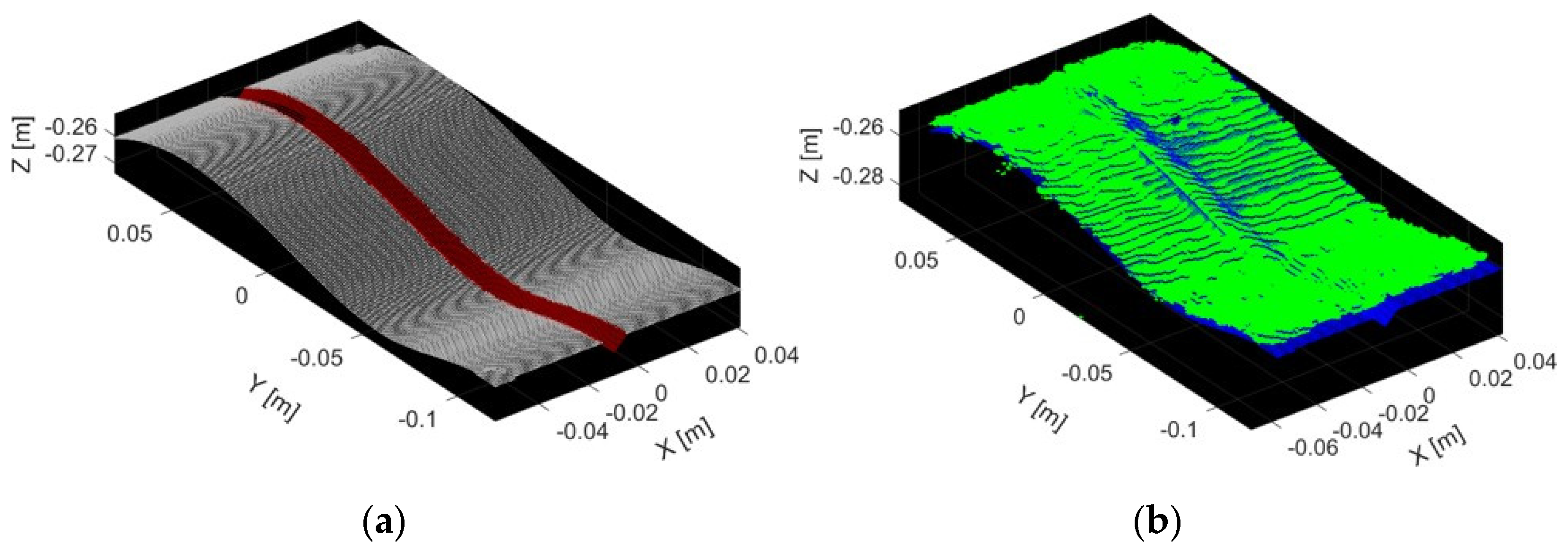
Color segmentation: This block represents the core of the proposed methodology that segment the welding area from the rest of the surface, in which the image was preprocessed considering the brightness of the scene to binarize the color image and look for the threshold at which a single frame of the point-cloud was vectorized to an XYZRGB format to using the Numpy and OpenCV library tools. However, to improve the selection of the points of interest, a change in the color space to hue saturation value (HSV) was used. The threshold was applied to the hue channel to find the color region, as well as to the saturation channel as a parameter for brightness.
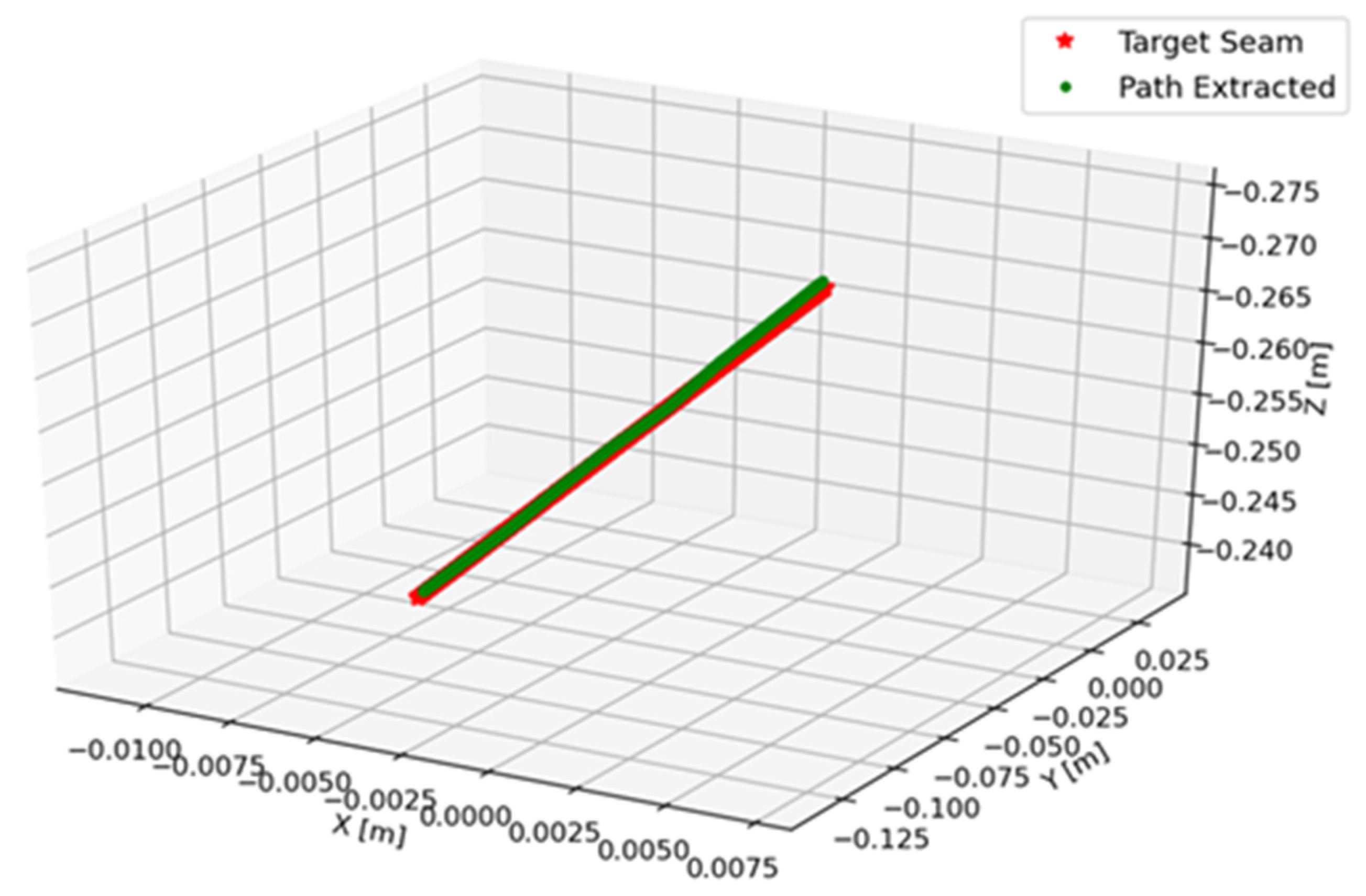
Trajectory planning: In order to calculate the trajectory from the color market segmented data in the previous module, following the methodology of Zhang et al. [15], a cubic B-spline interpolation algorithm was implemented to approximate the nonlinear dataset, the function was divided by knot points, and between the knots, the subset of data points a 5th order polynomial curve was applied to satisfies a smoothness requirement to the target weld seam points. It was planned that the trajectory would be smooth enough to be applied directly to the robot through a transformation matrix referenced to the welding direction.

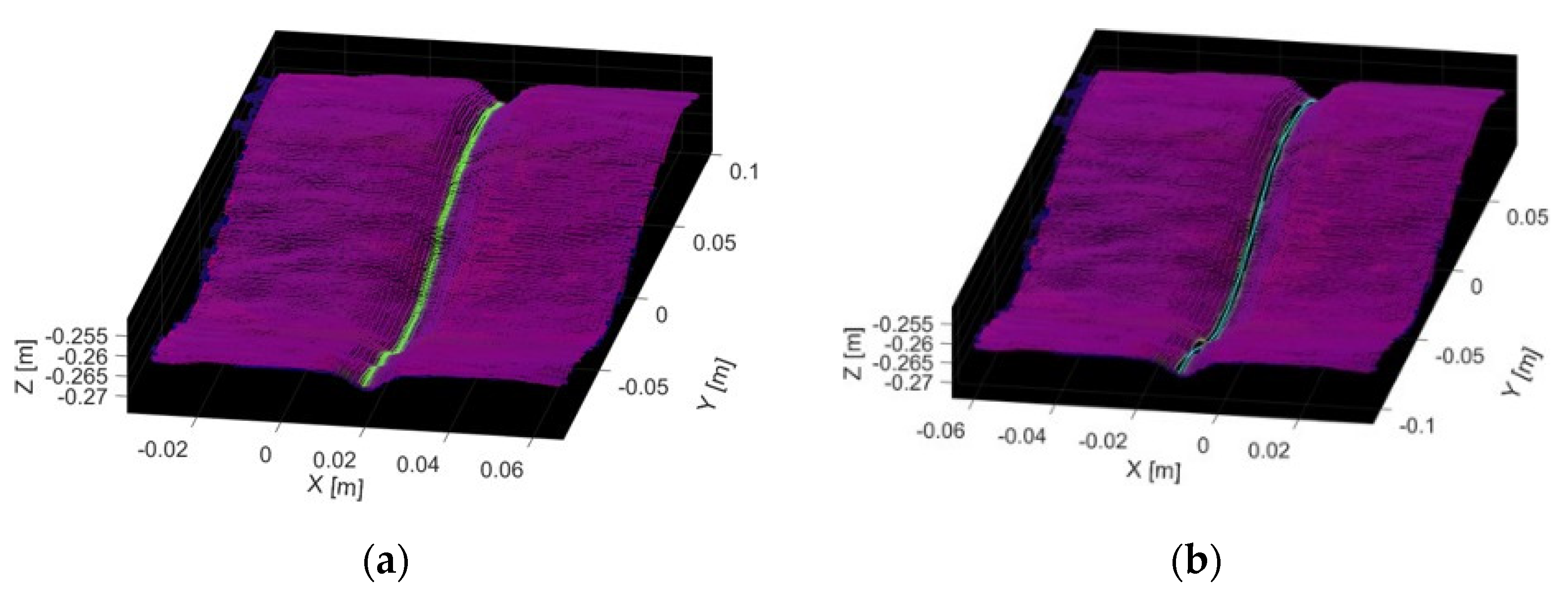
3.3. 3D Reconstruction with RealSense D435 Sensor

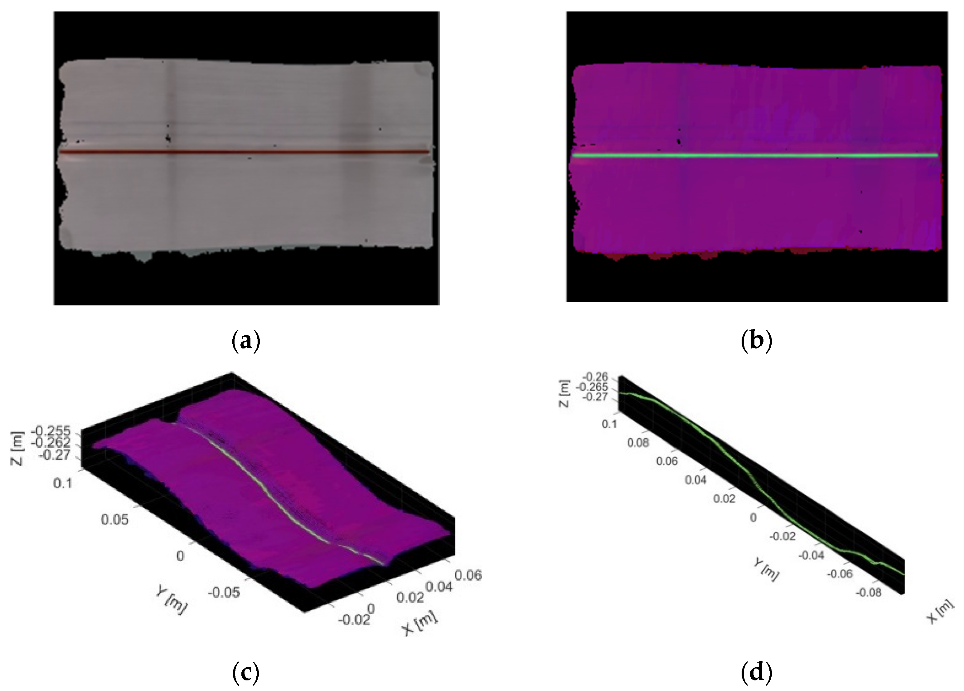
Before an in-depth analysis of the results of the trajectory extraction by the proposed algorithm, a study of the proposed vision system is necessary to evaluate the performance of the RealSense camera. We proceeded to execute the methodology described by Carfagni et al. [33], which evaluates the reconstruction capability of D415 and SR300 sensors, seeking to measure the error with which the sensor can reconstruct a surface. To this end, the RealSense D435 camera was located 30 cm away at the top of a flat surface where the test piece was placed. With this configuration, the 3D reconstruction of the surface was carried out through the first three blocks of the algorithm presented in the previous section to finally obtain the point cloud of the test piece.
The real point cloud of the test piece was generated by the CAD model exporting the pieces to a Polygon File Format (.ply), as shown in Figure 6. Once we had the target surface and the one calculated by the camera, we proceeded to run an ICP color registration algorithm [30] with which we could estimate the Euclidean point distance between the target and the 3D reconstruction surface.

4. Results

4.1. RealSense D435 3D Reconstruction Performance

The RealSense D435 camera was evaluated following the methodology described in Section 3.3. Figure 6 shows the result of the registration between both point clouds that provide the distance between the points of the 3D reconstruction to the closest point on the target surface. Three tests were carried out, and the results are shown in Table 2, in which the computed average distance and standard deviation are listed.

4.2. Trajectory Extraction of the Weld Bead by Colorimetry Point Cloud Segmentation

The RealSense sensor, by default, provides the color information of the scene in an RGB color space (RED, GREEN, BLUE), in the range of 0 to 255. To carry out this experiment, the color markers used in this color segmentation study were made in these primary colors. However, as mentioned before, the segmentation was performed by applying a threshold in the HSV color space channels. Table 3 shows the thresholds applied to achieve the segmentation of each color marker.
Figure 7 shows the result of generating the point cloud of the test piece to which a red color marker was applied in the weld zone—on the left is the target point cloud with color information in HSV color space, while the image on the right shows the result of the segmentation of the weld bead by applying the color filter to the point cloud.

4.3. Testing Trajectory Extraction of a V-Type Butt Joint

In this stage, the experimentation of the algorithm was implemented in its totality, as presented in Section 3.2, in which once the intended zone for applying the weld bead was captured, the algorithm implements a spline cubic interpolation, which calculates the path that smoothest the planning of the welding points that would require a robotic manipulator. Figure 8 shows the smooth computed trajectory over the reconstructed surface.
To evaluate the calculated trajectory, the points of the target path were obtained from the test piece designed in SolidWorks software and then compared with the trajectory calculated, using the ICP algorithm and filtering the target points that have the smallest Euclidean distance between the two trajectories. Finally, the RMSE error of each of the points between the target trajectory and the computed trajectory were calculated to verify the fitting results. Both trajectories are shown in Figure 9.
Table 4 shows the RMSE values in three tests that were conducted, where an offset with the surface Z axis can be observed. Comparing these results with the work of Yang et al. [21], we can infer that in some tests, we have comparable results in the Z error; however, the error range is higher, oscillating between 1.15 and 0.75 mm.
To have another control parameter in the results, we proceeded to calculate the Euclidean distance between the calculated trajectory and the desired CAD model trajectory. Table 5 shows a dispersion of the points in the trajectory with a standard deviation less than 0.5 mm.

4.4. Testing Trajectory Extraction of a Straight Butt Joint

Straight shape is a basic welding joint type commonly used in the industry, so a straight butt joint was constructed with a length of 20 cm and an inclination of 3° above the surface to demonstrate the flexibility of the system. Applying the previous algorithms, it was also possible to extract this trajectory. Figure 10 shows the tested surface reconstruction, to which a straight blue line was applied, and the trajectory calculated over the point cloud surface.
Table 6 shows the RMSE values, the average, and standard deviation between the calculated trajectory and the desired line model trajectory shown in Figure 11, within three tests that were conducted. Similar findings to previous results in RMSE and standard deviation show the flexibility of the system as a global acquisition system regardless of the workpiece.

5. Conclusions

To improve the efficiency of programming welding robots, this study proposed a color point cloud segmentation system to extract 3D paths. The major conclusions are generalized as follows:
(1)
A welding robot sensor based on stereo vision and RGB sensor was implemented in this paper that could finish the 3D color reconstruction task of welding workpiece, with a reconstruction standard deviation less than 1 mm, which is a parameter comparable to that shown by Carfagni [33] for similar devices.
(2)
In order to achieve quick and robust weld 3D path extraction, a color segmentation based on color point cloud reconstruction was performed, with thresholds in HSV color space and an interpolation of the segmented points. The trajectory extraction results show errors close to or below 1.1 mm for V-type butt joint and below 0.6 mm for a straight butt joint, comparable with other stereo vision studies; for example, Yang et al. [20] show that the measurement resolution is less than 0.7 mm for V-type butt joint, and in contrast, Zhou et al. [23] show a pose accuracy RMSE of 0.8 mm for a cylinder butt joint using a RealSense D415 sensor.
(3)
In addition to the above, the adaptability of the proposed trajectory extraction system, due to being a global capture system, shows results that encourage experimentation in V-type welding as one of the more studied in the literature, but also in other types of welding that would give a differential over most of the proposals found in the literature.
In the future, we aim to improve and complete our work. Firstly, we plan to conduct experiments on different test pieces and demonstrate that the proposed method is also suitable for different weld beads. In addition, we seek to analyze and extract the trajectory without applying a color marker, looking for the shadows or shines that are generated in the welding region. Finally, the measurement precision needs to be improved with a quality test of the proposed method against a laser sensor.

Author Contributions

Conceptualization, J.B.R.-S., E.C.-U. and A.G.-E.; methodology, J.B.R.-S., E.C.-U., J.A.E.C., R.L.S. and A.G.-E.; software, J.B.R.-S., J.A.E.C. and R.L.S.; validation J.B.R.-S.; formal analysis, J.B.R.-S., E.C.-U., J.A.E.C., R.L.S. and A.G.-E.; investigation, J.B.R.-S.; resources, J.B.R.-S. and J.A.E.C.; data curation, J.B.R.-S.; writing—original draft preparation, J.B.R.-S.; writing—review and editing, J.B.R.-S., E.C.-U., J.A.E.C., R.L.S. and A.G.-E.; visualization, J.B.R.-S.; supervision, E.C.-U. and A.G.-E.; project administration, J.B.R.-S. and A.G.-E.; funding acquisition, A.G.-E. All authors have read and agreed to the published version of the manuscript.

Funding

This research received no external funding.

Data Availability Statement

The study did not report any data.

Acknowledgments

Authors would like to acknowledge the support of Tecnologico de Monterrey and the financial support from CONACyT for the MSc studies of one of the authors (J.B.R.-S.).

Conflicts of Interest

The authors declare no conflict of interest.

References

  1. Ogbemhe, J.; Mpofu, K. Towards achieving a fully intelligent robotic arc welding: A review. Ind. Robot Int. J. 2015, 42, 475–484. [Google Scholar] [CrossRef]
  2. Pan, Z.; Polden, J.; Larkin, N.; Van Duin, S.; Norrish, J. Recent progress on programming methods for Industrial Robots. Robot. Comput. Integr. Manuf. 2012, 28, 87–94. [Google Scholar] [CrossRef] [Green Version]
  3. Pérez, L.; Rodríguez, Í.; Rodríguez, N.; Usamentiaga, R.; García, D.F. Robot Guidance Using Machine Vision Techniques in Industrial Environments: A Comparative Review. Sensors 2016, 16, 335. [Google Scholar] [CrossRef]
  4. Lei, T.; Rong, Y.; Wang, H.; Huang, Y.; Li, M. A review of vision-aided robotic welding. Comput. Ind. 2020, 123, 103326. [Google Scholar] [CrossRef]
  5. Kiddee, P.; Fang, Z.; Tan, M. Visual recognition of the initial and end points of lap joint for welding robots. In 2014 IEEE International Conference on Information and Automation (ICIA); IEEE: Piscataway, NJ, USA, 2014. [Google Scholar] [CrossRef]
  6. Ye, Z.; Fang, G.; Chen, S.; Dinham, M. A robust algorithm for weld seam extraction based on prior knowledge of weld seam. Sens. Rev. 2013, 33, 125–133. [Google Scholar] [CrossRef]
  7. Yang, L.; Li, E.; Long, T.; Fan, J.; Mao, Y.; Fang, Z.; Liang, Z. A welding quality detection method for arc welding robot based on 3D reconstruction with SFS algorithm. Int. J. Adv. Manuf. Technol. 2017, 94, 1209–1220. [Google Scholar] [CrossRef]
  8. Villan, A.F.; Acevedo, R.G.; Alvarez, E.A.; Campos-Lopez, A.M.; Garcia-Martinez, D.F.; Fernandez, R.U.; Meana, M.J.; Sanchez, J.M.G. Low-cost system for weld tracking based on artificial vision. IEEE Trans. Ind. Appl. 2011, 47, 1159–1167. [Google Scholar] [CrossRef]
  9. Liu, F.Q.; Wang, Z.Y.; Ji, Y. Precise initial weld position identification of a fillet weld seam using laser vision technology. Int. J. Adv. Manuf. Technol. 2018, 99, 2059–2068. [Google Scholar] [CrossRef]
  10. Li, X.; Li, X.; Ge, S.S.; Khyam, M.O.; Luo, C. Automatic welding Seam tracking and identification. IEEE Trans. Ind. Electron. 2017, 64, 7261–7271. [Google Scholar] [CrossRef]
  11. Fan, J.; Jing, F.; Yang, L.; Teng, L.; Tan, M. A precise initial weld point guiding method of micro-gap weld based on structured light vision sensor. IEEE Sens. J. 2019, 19, 322–331. [Google Scholar] [CrossRef]
  12. Zeng, J.; Chang, B.; Du, D.; Wang, L.; Chang, S.; Peng, G.; Wang, W. A Weld Position Recognition Method Based on Directional and Structured Light Information Fusion in Multi-Layer/Multi-Pass Welding. Sensors 2018, 18, 129. [Google Scholar] [CrossRef] [PubMed] [Green Version]
  13. Guo, J.; Zhu, Z.; Sun, B.; Yu, Y. A novel multifunctional visual sensor based on combined laser structured lights and its anti-jamming detection algorithms. Weld. World 2018, 63, 313–322. [Google Scholar] [CrossRef]
  14. Kos, M.; Arko, E.; Kosler, H.; Jezeršek, M. Remote laser welding with in-line adaptive 3D seam tracking. Int. J. Adv. Manuf. Technol. 2019, 103, 4577–4586. [Google Scholar] [CrossRef] [Green Version]
  15. Zhang, K.; Yan, M.; Huang, T.; Zheng, J.; Li, Z. 3D reconstruction of complex spatial weld seam for autonomous welding by laser structured light scanning. J. Manuf. Process. 2019, 39, 200–207. [Google Scholar] [CrossRef]
  16. Chen, X.Z.; Chen, S.B. The autonomous detection and guiding of start welding position for arc welding robot. Ind. Robot Int. J. 2010, 37, 70–78. [Google Scholar] [CrossRef]
  17. Dinham, M.; Fang, G. Autonomous weld seam identification and localisation using eye-in-hand stereo vision for robotic arc welding. Robot. Comput. Integr. Manuf. 2013, 29, 288–301. [Google Scholar] [CrossRef]
  18. Ma, H.; Wei, S.; Lin, T.; Chen, S.; Li, L. Binocular vision system for both weld pool and root gap in robot welding process. Sens. Rev. 2010, 30, 116–123. [Google Scholar] [CrossRef]
  19. Xiao, R.; Xu, Y.; Hou, Z.; Chen, C.; Chen, S. An adaptive feature extraction algorithm for multiple typical seam tracking based on vision sensor in robotic arc welding. Sens. Actuators A Phys. 2019, 297, 111533. [Google Scholar] [CrossRef]
  20. Yang, L.; Li, E.; Long, T.; Fan, J.; Liang, Z. A novel 3-d path extraction method for arc welding robot based on stereo structured light sensor. IEEE Sens. J. 2019, 19, 763–773. [Google Scholar] [CrossRef]
  21. Yang, L.; Liu, Y.; Peng, J.; Liang, Z. A novel system for off-line 3D seam extraction and path planning based on point cloud segmentation for arc welding robot. Robot. Comput. Integr. Manuf. 2020, 64, 101929. [Google Scholar] [CrossRef]
  22. Maiolino, P.; Woolley, R.; Branson, D.; Benardos, P.; Popov, A.; Ratchev, S. Flexible robot sealant dispensing cell using RGB-D sensor and off-line programming. Robot. Comput. Integr. Manuf. 2017, 48, 188–195. [Google Scholar] [CrossRef] [Green Version]
  23. Zhou, P.; Peng, R.; Xu, M.; Wu, V.; Navarro-Alarcon, D. Path planning with automatic seam extraction over point cloud models for robotic arc welding. IEEE Robot. Autom. Lett. 2021, 6, 5002–5009. [Google Scholar] [CrossRef]
  24. Tippetts, B.; Lee, D.J.; Lillywhite, K.; Archibald, J. Review of stereo vision algorithms and their suitability for resource-limited systems. J. Real-Time Image Process. 2013, 11, 5–25. [Google Scholar] [CrossRef]
  25. Ke, F.; Liu, H.; Zhao, D.; Sun, G.; Xu, W.; Feng, W. A high precision image registration method for measurement based on the stereo camera system. Optik 2020, 204, 164186. [Google Scholar] [CrossRef]
  26. Zhang, S. High-speed 3D shape measurement with structured light methods: A review. Opt. Lasers Eng. 2018, 106, 119–131. [Google Scholar] [CrossRef]
  27. Geng, J. Structured-light 3D surface imaging: A tutorial. Adv. Opt. Photonics 2011, 3, 128. [Google Scholar] [CrossRef]
  28. Bi, Z.M.; Wang, L. Advances in 3D data acquisition and processing for industrial applications. Robot. Comput. Integr. Manuf. 2010, 26, 403–413. [Google Scholar] [CrossRef]
  29. Laganiere, R.; Gilbert, S.; Roth, G. Robust object pose estimation from feature-based stereo. IEEE Trans. Instrum. Meas. 2006, 55, 1270–1280. [Google Scholar] [CrossRef]
  30. Park, J.; Zhou, Q.-Y.; Koltun, V. Colored point cloud registration revisited. In 2017 IEEE International Conference on Computer Vision (ICCV); IEEE: Piscataway, NJ, USA, 2017. [Google Scholar] [CrossRef]
  31. Huang, X.; Zhang, J.; Wu, Q.; Fan, L.; Yuan, C. A coarse-to-fine algorithm for matching and registration in 3d CROSS-SOURCE point clouds. IEEE Trans. Circuits Syst. Video Technol. 2018, 28, 2965–2977. [Google Scholar] [CrossRef] [Green Version]
  32. Grunnet-Jepsen, A.; Tong, D. Depth Post-Processing FOR Intel® REALSENSE™ Depth Camera D400 Series. Available online: https://dev.intelrealsense.com/docs/depth-post-processing (accessed on 12 September 2021).
  33. Carfagni, M.; Furferi, R.; Governi, L.; Santarelli, C.; Servi, M.; Uccheddu, F.; Volpe, Y. Metrological and Critical Characterization of the Intel D415 Stereo Depth Camera. Sensors 2019, 19, 489. [Google Scholar] [CrossRef] [Green Version]
Figure 1. Geometric relationship of a stereo camera configuration. The 3D image of target scene at point P.
Automation 02 00016 g001
Figure 2. Point cloud color map registration: (a) depth information; (b) color information; (c) colored point cloud through RGB registration.
Automation 02 00016 g002
Figure 3. Experimental setup: camera mounted on a pedestal with top view of the working object.
Automation 02 00016 g003
Figure 4. The model of the curved V-type butt joint with a red marker: (a) front view; (b) right view; (c) top view; (d) isometric view.
Automation 02 00016 g004
Figure 5. The flowchart of path extraction.
Automation 02 00016 g005
Figure 6. 3D Reconstruction evaluation: (a) target point cloud; (b) the result of ICP color registration between target and 3D.
Automation 02 00016 g006
Figure 7. Color Segmentation: (a) RGB image; (b) image with HSV transformation; (c) point cloud with HSV data; (d) points of seam filter by color segmentation.
Automation 02 00016 g007
Figure 8. V-type butt joint trajectory extraction: (a) point cloud with HSV data; (b) surface with the computed path.
Automation 02 00016 g008
Figure 9. Workpiece target path vs. computed trajectory.
Automation 02 00016 g009
Figure 10. Straight butt joint trajectory extraction: (a) workpiece; (b) point cloud with HSV data; (c) surface with the computed path.
Automation 02 00016 g010
Figure 11. Target straight butt joint trajectory vs. computed trajectory.
Automation 02 00016 g011
Table 1. Machining parameters for the workpiece manufacture. Milling parameters: Vc = cutting speed, RPM = spindle revolution per minute; F = feed rate.
Tool PathTool-Vc (m/min)RPMF (mm)
FacingFacer 2.5”6503500300
PocketingFlat 0.25”12060007
DrillingDrill 0.203”5030486
Tangent to curveFlat 1.0”350450040
Wall machiningFlat 0.5”200500030
Z levelFlat 0.437”250550047
Z finishingBall 0.25”100600032
Table 2. RealSense D435 evaluation to perform a 3D reconstruction.
AverageStandard Deviation
Test 10.704 mm0.378 mm
Test 21.053 mm0.623 mm
Test 31.284 mm0.738 mm
Table 3. Color threshold for point cloud segmentation by colorimetry.
HueSaturation
Red160–180100–255
Green30–50100–255
Blue110–12050–255
Table 4. Trajectory RMSE error for V-type butt joint.
XYZ
Test 10.063 mm0. 184 mm0.952 mm
Test 20.046 mm0.195 mm1.059 mm
Test 30.010 mm0.145 mm0.739 mm
Table 5. Average and standard deviation between CAD and computed trajectory for V-type butt joint.
AverageStandard Deviation
Test 10.70 mm0.30 mm
Test 20.80 mm0.30 mm
Test 30.80 mm0.30 mm
Table 6. Trajectory RMSE error for V-type butt joint.
XYZAverageStandard Deviation
Test 10.142 mm0.075 mm0.683 mm0.60 mm0.20 mm
Test 20.124 mm0.072 mm0.530 mm0.50 mm0.20 mm
Test 30.180 mm0.069 mm0.494 mm0.50 mm0.20 mm
Publisher’s Note: MDPI stays neutral with regard to jurisdictional claims in published maps and institutional affiliations.

