
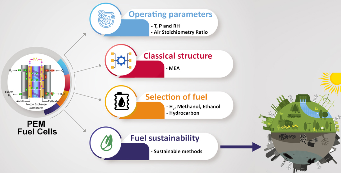
The Operating Parameters, Structural Composition, and Fuel Sustainability Aspects of PEM Fuel Cells: A Mini Review


Abstract
:
1. Introduction
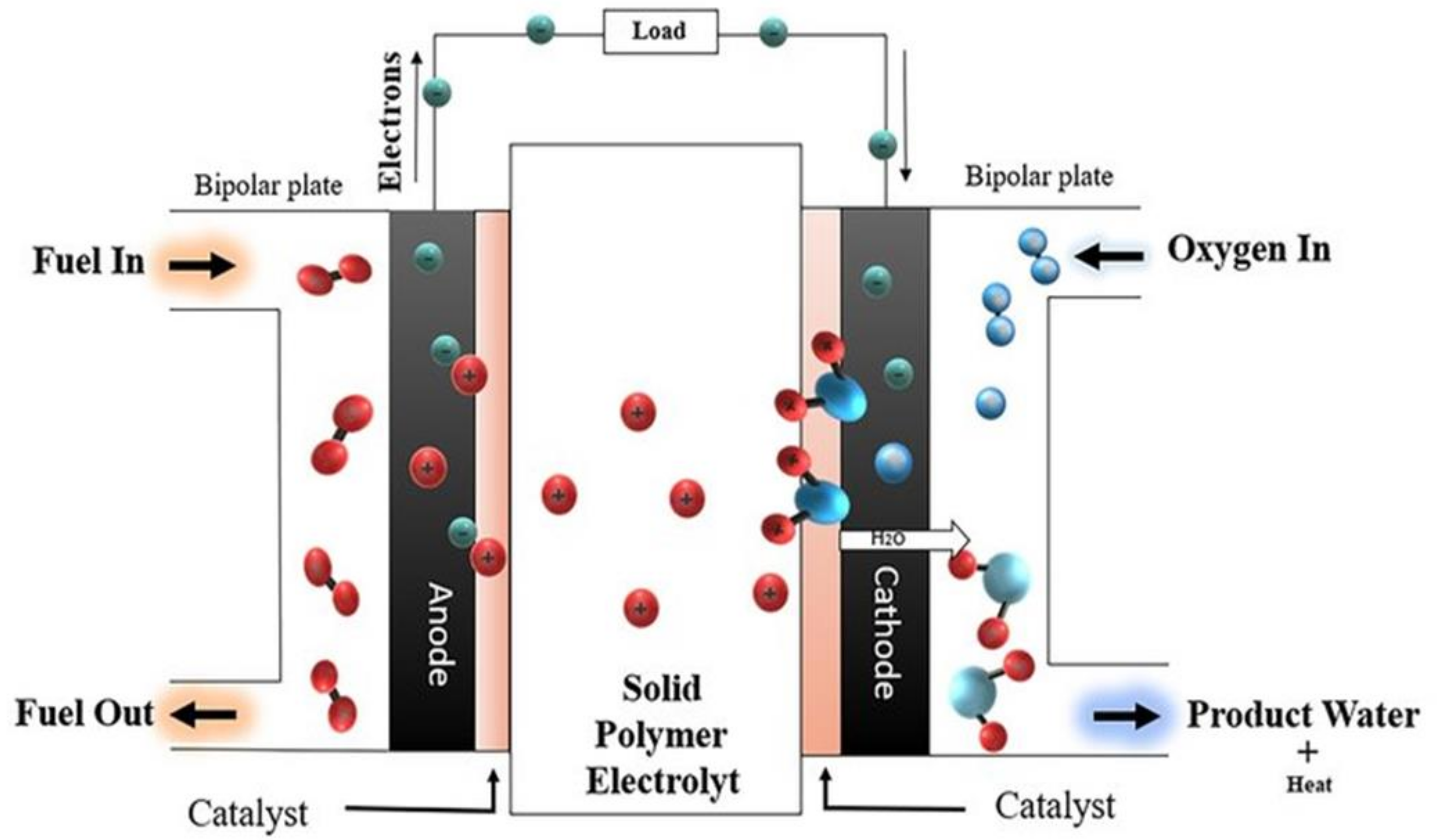
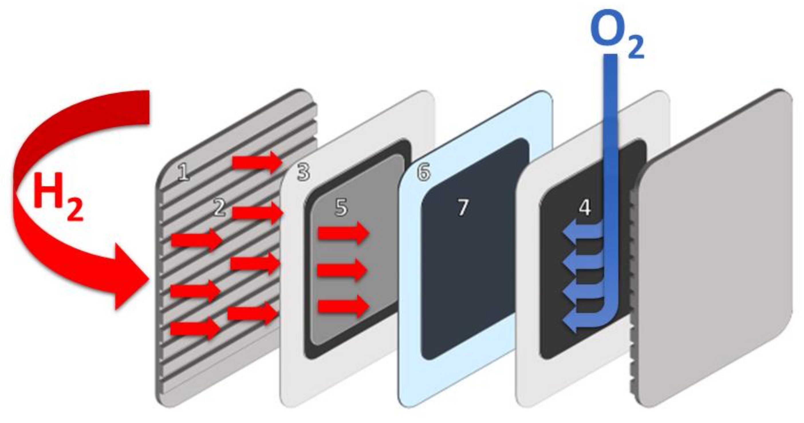
2. PEMFC Operation
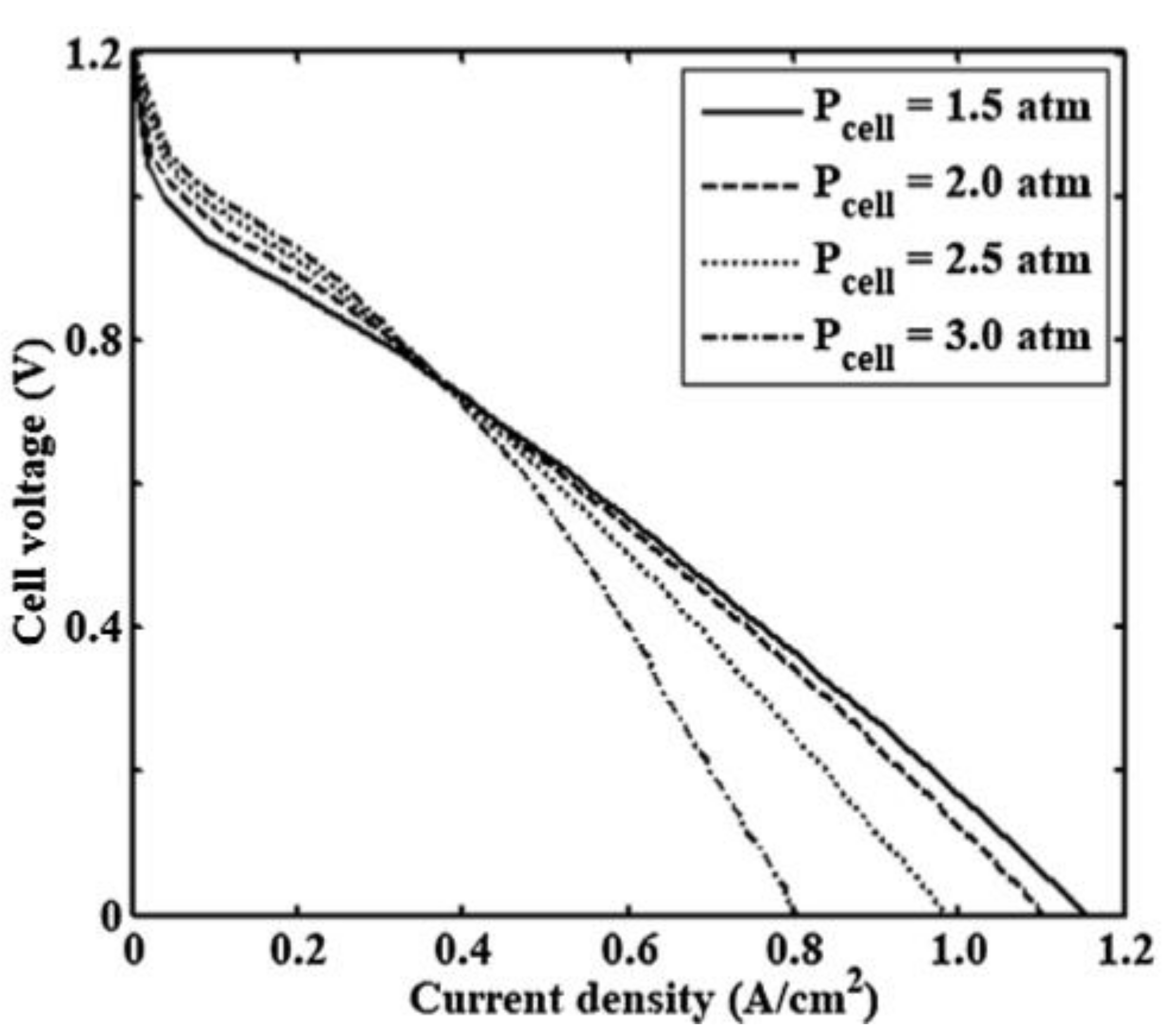
2.1. The Fuel Cell Operation Pressure
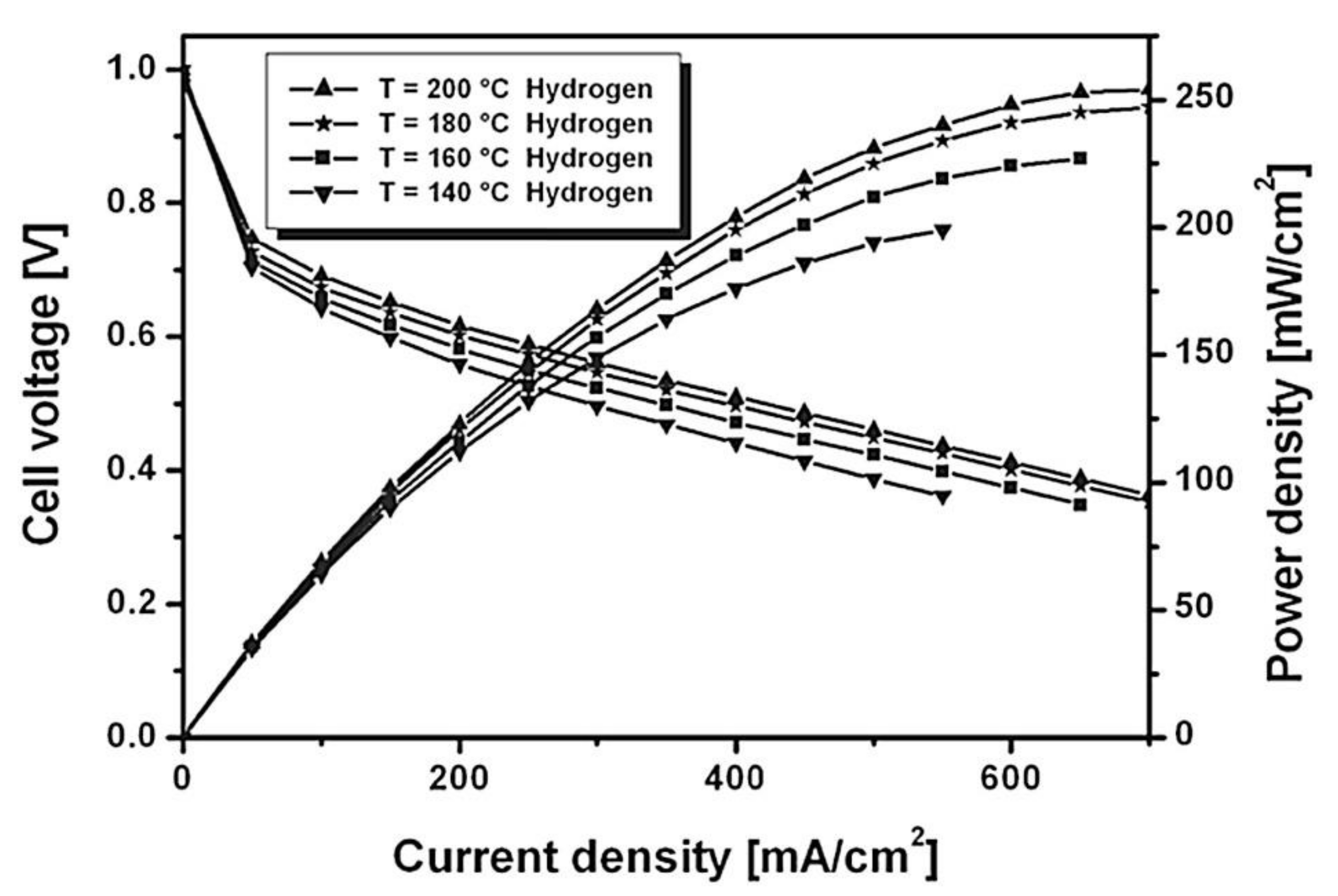
2.2. The Fuel Cell Operation Temperature
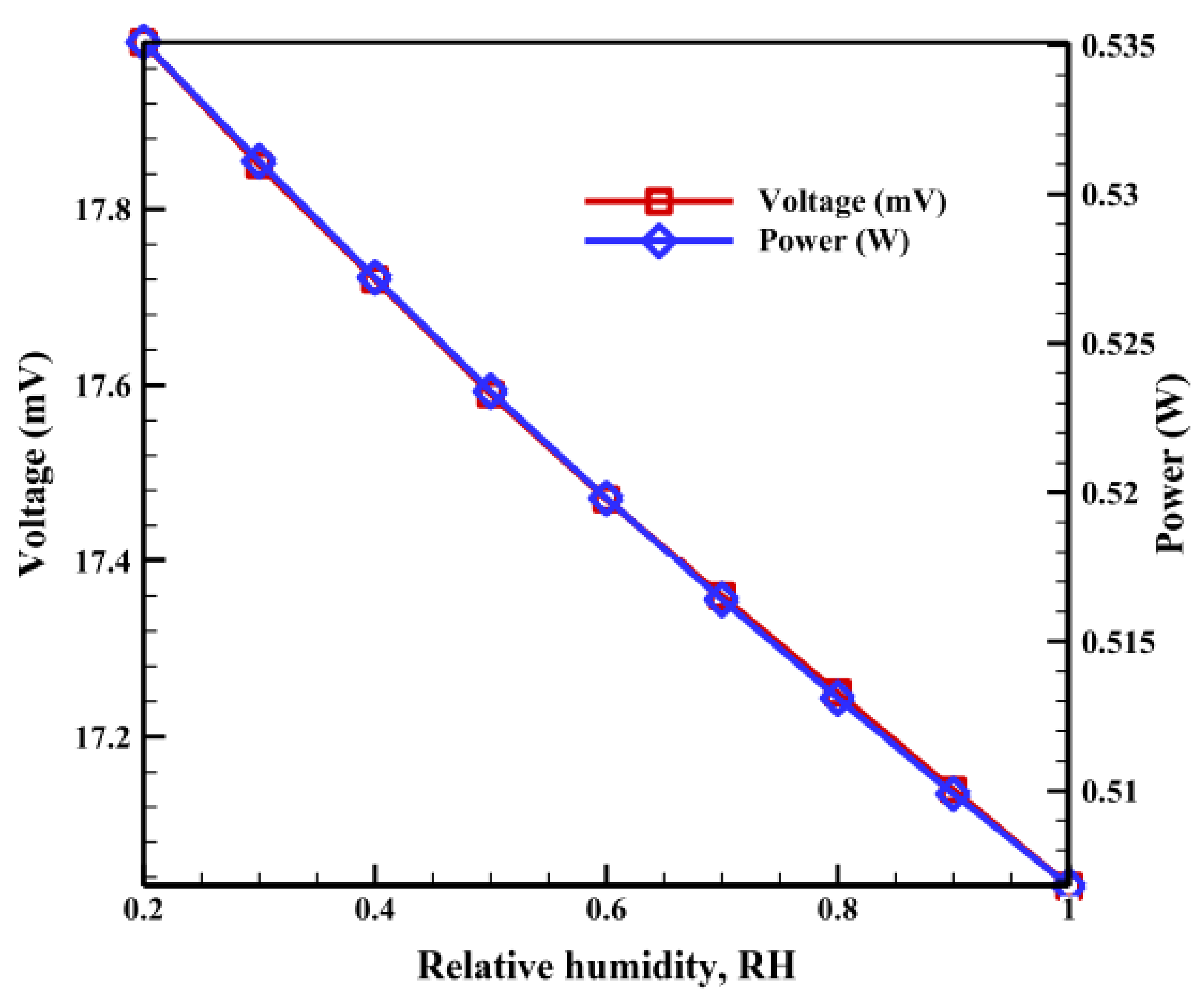
2.3. Relative Humidity
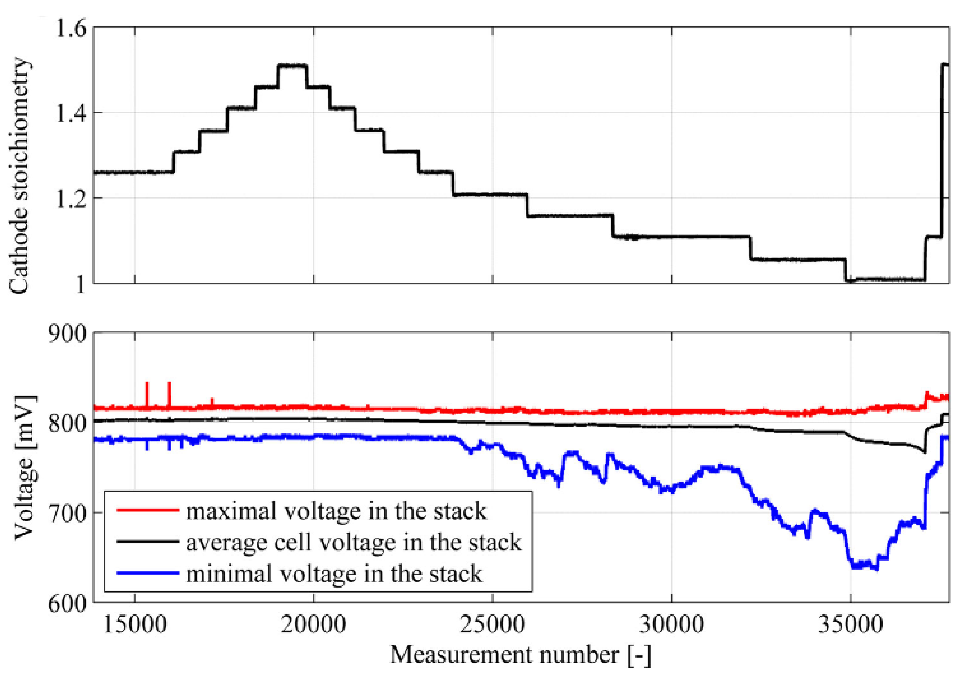
2.4. Air Stoichiometry Ratio
3. Materials and Structure of PEMFC
3.1. Anodes and Cathodes
3.2. The Membrane
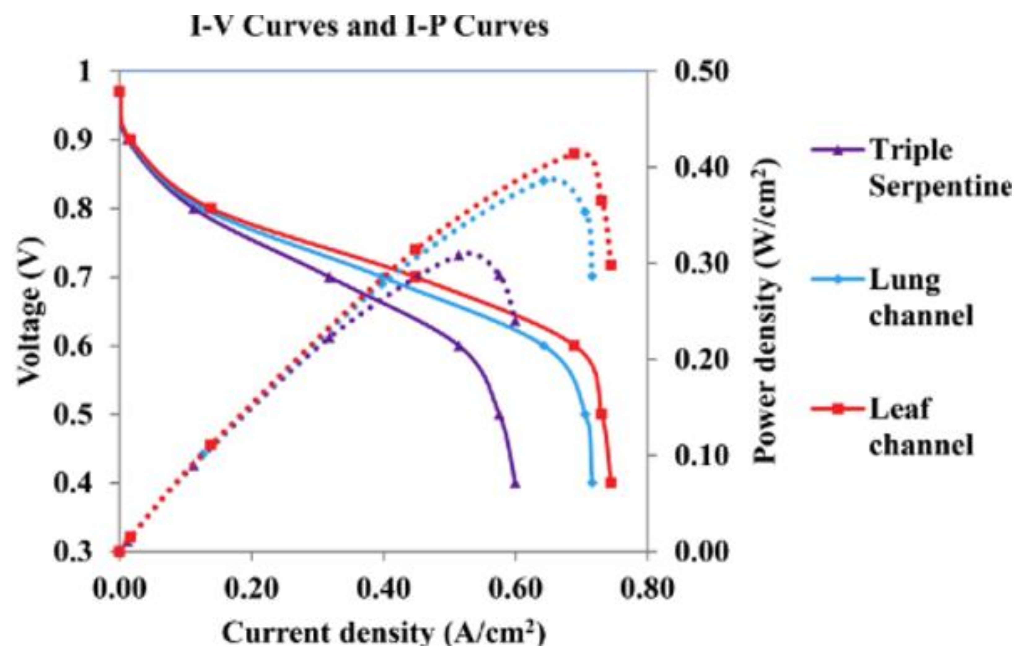
3.3. Bipolar Plates (BPs)
4. Fuels for PEMFCs
4.1. Hydrogen Fuel
4.2. Methanol Fuel
4.3. Hydrocarbon Fuels
4.4. Ethanol Fuel
5. Sustainability Aspects of Fuels
5.1. Sustainable Hydrogen Fuel
5.2. Sustainable Methanol Fuel
5.3. Sustainable Hydrocarbon Fuels
5.4. Sustainable Ethanol Fuel
6. Challenges of Operation
7. Conclusions
Author Contributions
Funding
Institutional Review Board Statement
Informed Consent Statement
Data Availability Statement
Conflicts of Interest
References
- Tawalbeh, M.; Al-Ismaily, M.; Kruczek, B.; Tezel, F.H. Modeling the transport of CO2, N2, and their binary mixtures through highly permeable silicalite-1 membranes using Maxwell−Stefan equations. Chemosphere 2021, 263, 127935. [Google Scholar] [CrossRef] [PubMed]
- Leykun, M.G.; Mekonen, M.W. Investigation of the Performance and Emission Characteristics of Diesel Engine Fueled with Biogas-Diesel Dual Fuel. Fuels 2022, 3, 15–30. [Google Scholar] [CrossRef]
- Martis, R.; Al-Othman, A.; Alkasrawi, M.; Tawalbeh, M. Fuel cells for carbon capture and power generation: Simulation studies. Int. J. Hydrogen Energy 2021, 46, 6139–6149. [Google Scholar] [CrossRef]
- Abdelsalam, E.; Almomani, F.; Kafiah, F.; Almaitta, E.; Tawalbeh, M.; Khasawneh, A.; Habash, D.; Omar, A.; Alkasrawi, M. A New Sustainable and Novel Hybrid Solar Chimney Power Plant Design for Power Generation and Seawater Desalination. Sustainability 2021, 13, 12100. [Google Scholar] [CrossRef]
- Aricò, A.S.; Srinivasan, S.; Antonucci, V. DMFCs: From Fundamental Aspects to Technology Development. Fuel Cells 2001, 1, 133–161. [Google Scholar] [CrossRef]
- Nauman Javed, R.M.; Al-Othman, A.; Nancarrow, P.; Tawalbeh, M. Zirconium silicate-ionic liquid membranes for high temperature hydrogen PEM fuel cells. Int. J. Hydrogen Energy 2022. [Google Scholar] [CrossRef]
- Carrette, L.; Friedrich, K.A.; Stimming, U. Fuel Cells: Principles, Types, Fuels, and Applications. ChemPhysChem 2000, 1, 162–193. [Google Scholar] [CrossRef]
- Jang, G.-E.; Cho, G.-Y. Effects of Ag Current Collecting Layer Fabricated by Sputter for 3D-Printed Polymer Bipolar Plate of Ultra-Light Polymer Electrolyte Membrane Fuel Cells. Sustainability 2022, 14, 2997. [Google Scholar] [CrossRef]
- Al-arydah, M.; Carraro, T. Reviewing the mathematical validity of a fuel cell cathode model. Existence of weak bounded solution. Comput. Math Appl. 2019, 77, 1425–1436. [Google Scholar] [CrossRef]
- Tawalbeh, M.; Al-Othman, A.; Ka’ki, A.; Farooq, A.; Alkasrawi, M. Highly proton conductive membranes based on lignin/ZrP/PTFE composite for high temperature PEM fuel cells. In 2022 Advances in Science and Engineering Technology International Conferences (ASET); IEEE: Manhattan, NY, USA, 2022; pp. 1–5. [Google Scholar] [CrossRef]
- Tellez-Cruz, M.M.; Escorihuela, J.; Solorza-Feria, O.; Compañ, V. Proton Exchange Membrane Fuel Cells (PEMFCs): Advances and Challenges. Polymers 2021, 13, 3064. [Google Scholar] [CrossRef]
- Alaswad, A.; Omran, A.; Sodre, J.R.; Wilberforce, T.; Pignatelli, G.; Dassisti, M.; Baroutaji, A.; Olabi, A.G. Technical and Commercial Challenges of Proton-Exchange Membrane (PEM) Fuel Cells. Energies 2020, 14, 144. [Google Scholar] [CrossRef]
- Alashkar, A.; Al-othman, A.; Tawalbeh, M.; Qasim, M. A Critical Review on the Use of Ionic Liquids in Proton Exchange Membrane Fuel Cells. Membranes 2022, 12, 178. [Google Scholar] [CrossRef]
- Verma, A.; Basu, S. Recent Trends in Fuel Cell Science and Technology; Springer: Berlin/Heidelberg, Germany, 2007; pp. 157–187. [Google Scholar] [CrossRef]
- Holton, O.T.; Stevenson, J.W. The role of platinum in proton exchange membrane fuel cells. Platin. Met. Rev. 2013, 57, 259–271. [Google Scholar] [CrossRef]
- Wu, B.; Zhao, M.; Shi, W.; Liu, W.; Liu, J.; Xing, D.; Yao, Y.; Hou, Z.; Ming, P.; Gu, J.; et al. The degradation study of Nafion/PTFE composite membrane in PEM fuel cell under accelerated stress tests. Int. J. Hydrogen Energy 2014, 39, 14381–14390. [Google Scholar] [CrossRef]
- Dincer, I. Green methods for hydrogen production. Int. J. Hydrogen Energy 2012, 37, 1954–1971. [Google Scholar] [CrossRef]
- Matzen, M.; Alhajji, M.; Demirel, Y. Chemical storage of wind energy by renewable methanol production: Feasibility analysis using a multi-criteria decision matrix. Energy 2015, 93, 343–353. [Google Scholar] [CrossRef] [Green Version]
- Renau, J.; García, V.; Domenech, L.; Verdejo, P.; Real, A.; Giménez, A.; Sánchez, F.; Lozano, A.; Barreras, F. Novel use of green hydrogen fuel cell-based combined heat and power systems to reduce primary energy intake and greenhouse emissions in the building sector. Sustainability 2021, 13, 1776. [Google Scholar] [CrossRef]
- Shroti, N.; Daletou, M.K. The Pt–Co alloying effect on the performance and stability of high temperature PEMFC cathodes. Int. J. Hydrogen Energy 2022, 47, 16235–16248. [Google Scholar] [CrossRef]
- Xuan, J.; Liu, Y.; Xu, L.; Bai, S.; Xin, Y.; Wang, L.; Zhang, G.; Su, Y.; Xue, L.; Li, L. Investigation of acidity on corrosion behavior and surface properties of SS304 in simulated PEMFC cathode environments. Int. J. Hydrogen Energy 2022, 47, 22938–22951. [Google Scholar] [CrossRef]
- Zhu, D.; Yang, Y.; Ma, T. Evaluation the Resistance Growth of Aged Vehicular Proton Exchange Membrane Fuel Cell Stack by Distribution of Relaxation Times. Sustainability 2022, 14, 5677. [Google Scholar] [CrossRef]
- Baroutaji, A.; Arjunan, A.; Ramadan, M.; Robinson, J.; Alaswad, A.; Abdelkareem, M.A.; Olabi, A.G. Advancements and prospects of thermal management and waste heat recovery of PEMFC. Int. J. Thermofluids 2021, 9, 100064. [Google Scholar] [CrossRef]
- Al-arydah, M.; Novruzi, A. Existence of weak positive solutions to a nonlinear PDE system around a triple phase boundary, coupling domain and boundary variables. J. Math Anal. Appl. 2011, 382, 686–700. [Google Scholar] [CrossRef] [Green Version]
- Moradi, R.; Groth, K.M. Hydrogen storage and delivery: Review of the state of the art technologies and risk and reliability analysis. Int. J. Hydrogen Energy 2019, 44, 12254–12269. [Google Scholar] [CrossRef]
- Meyers, R.A. Encyclopedia of Sustainability Science and Technology; Springer: Manhattan, NY, USA, 2012. [Google Scholar] [CrossRef]
- Bhattacharya, P.K. Water flooding in the proton exchange membrane fuel cell. Directions 2015, 15. [Google Scholar]
- Al-Othman, A.; Tawalbeh, M.; Martis, R.; Dhou, S.; Orhan, M.; Qasim, M.; Olabi, A.G. Artificial intelligence and numerical models in hybrid renewable energy systems with fuel cells: Advances and prospects. Energy Convers. Manag. 2022, 253, 115154. [Google Scholar] [CrossRef]
- Maheshwari, K.; Sharma, S.; Sharma, A.; Verma, S. A Review: Fuel cell a sustainable future. Int. J. Chem. Stud. 2018, 6, 2588–2591. [Google Scholar]
- Barbir, F. Chapter 3—Fuel Cell Electrochemistry. In Barbir FBT-PEMFC; Academic Press: Burlington, NJ, USA, 2005; pp. 33–72. [Google Scholar] [CrossRef]
- Xuan, J.; Leung, M.K.H.; Leung, D.Y.C.; Ni, M. A review of biomass-derived fuel processors for fuel cell systems. Renew. Sustain. Energy Rev. 2009, 13, 1301–1313. [Google Scholar] [CrossRef]
- Gencoglu, M.T.; Ural, Z. Design of a PEM fuel cell system for residential application. Int. J. Hydrogen Energy 2009, 34, 5242–5248. [Google Scholar] [CrossRef]
- Silaa, M.Y.; Derbeli, M.; Barambones, O.; Cheknane, A. Design and Implementation of High Order Sliding Mode Control for PEMFC Power System. Energies 2020, 13, 4317. [Google Scholar] [CrossRef]
- Baroutaji, A.; Carton, J.G.; Sajjia, M.; Olabi, A.G. Materials in PEM Fuel Cells; Elsevier Ltd.: Amsterdam, The Netherlands, 2016. [Google Scholar] [CrossRef]
- Askaripour, H. Effect of operating conditions on the performance of a PEM fuel cell. Int. J. Heat Mass Transf. 2019, 144, 118705. [Google Scholar] [CrossRef]
- Li, Y.; Zhou, Z.; Liu, X.; Wu, W.T. Modeling of PEM fuel cell with thin MEA under low humidity operating condition. Appl. Energy 2019, 242, 1513–1527. [Google Scholar] [CrossRef]
- Peng, X.; Wu, W.; Zhang, Y.; Yang, W. Determination of operating parameters for PEM fuel cell using support vector machines approach. J. Energy Storage 2017, 13, 409–417. [Google Scholar] [CrossRef]
- Toghyani, S.; Afshari, E.; Baniasadi, E. A parametric comparison of three fuel recirculation system in the closed loop fuel supply system of PEM fuel cell. Int. J. Hydrogen Energy 2019, 44, 7518–7530. [Google Scholar] [CrossRef]
- Daud, W.R.W.; Rosli, R.E.; Majlan, E.H.; Hamid, S.A.A.; Mohamed, R.; Husaini, T. PEM fuel cell system control: A review. Renew. Energy 2017, 113, 620–638. [Google Scholar] [CrossRef]
- Badduri, S.R.; Srinivasulu, G.N.; Rao, S.S. Influence of bio-inspired flow channel designs on the performance of a PEM fuel cell. Chin. J. Chem. Eng. 2020, 28, 824–831. [Google Scholar] [CrossRef]
- Xia, L.; Zhang, C.; Hu, M.; Jiang, S.; Chin, C.S.; Gao, Z.; Liao, Q. Investigation of parameter effects on the performance of high-temperature PEM fuel cell. Int. J. Hydrogen Energy 2018, 43, 23441–23449. [Google Scholar] [CrossRef]
- Wannek, C.; Dohle, H.; Mergel, J.; Stolten, D. Novel VHT-PEFC MEAs Based on ABPBI Membranes for APU Applications. ECS Trans. 2008, 12, 29–39. [Google Scholar] [CrossRef]
- Cheng, S.J.; Miao, J.M.; Wu, S.J. Numerical optimization design of PEM fuel cell performance applying the Taguchi method. World Acad. Sci. Eng. Technol. Int. J. Phys. Math. Sci. 2010, 4, 526–532. [Google Scholar]
- Chen, H.; Liu, B.; Liu, R.; Weng, Q.; Zhang, T.; Pei, P. Optimal interval of air stoichiometry under different operating parameters and electrical load conditions of proton exchange membrane fuel cell. Energy Convers. Manag. 2020, 205, 112398. [Google Scholar] [CrossRef]
- Liu, D.; Lin, R.; Feng, B.; Yang, Z. Investigation of the effect of cathode stoichiometry of proton exchange membrane fuel cell using localized electrochemical impedance spectroscopy based on print circuit board. Int. J. Hydrogen Energy 2019, 44, 7564–7573. [Google Scholar] [CrossRef]
- Zhang, Q.; Lin, R.; Técher, L.; Cui, X. Experimental study of variable operating parameters effects on overall PEMFC performance and spatial performance distribution. Energy 2016, 115, 550–560. [Google Scholar] [CrossRef]
- Yan, Q.; Toghiani, H.; Causey, H. Steady state and dynamic performance of proton exchange membrane fuel cells (PEMFCs) under various operating conditions and load changes. J. Power Sources 2006, 161, 492–502. [Google Scholar] [CrossRef]
- Lin, R.; Yu, X.; Chen, L.; Tang, S.; Yin, X.; Hao, Z. Structure majorization on the surface of microporous layer in polymer electrolyte membrane fuel cells to optimize performance and durability. Energy Convers. Manag. 2021, 243, 114319. [Google Scholar] [CrossRef]
- Qu, S.; Li, X.; Hou, M.; Shao, Z.; Yi, B. The effect of air stoichiometry change on the dynamic behavior of a proton exchange membrane fuel cell. J. Power Sources 2008, 185, 302–310. [Google Scholar] [CrossRef]
- Polak, A.; Grzeczka, G.; Piłat, T. Influence of cathode stoichiometry on operation of PEM fuel cells’ stack supplied with pure oxygen. J. Mar. Eng. Technol. 2018, 16, 283–290. [Google Scholar] [CrossRef]
- Kim, B.; Cha, D.; Kim, Y. The effects of air stoichiometry and air excess ratio on the transient response of a PEMFC under load change conditions. Appl. Energy 2015, 138, 143–149. [Google Scholar] [CrossRef]
- Wang, Y.; Ruiz Diaz, D.F.; Chen, K.S.; Wang, Z.; Adroher, X.C. Materials, technological status, and fundamentals of PEM fuel cells—A review. Mater. Today 2020, 32, 178–203. [Google Scholar] [CrossRef]
- Latorrata, S.; Mariani, M.; Stampino, P.G.; Cristiani, C.; Dotelli, G. Graphene-based microporous layers for enhanced performance in PEM fuel cells. Mater. Mater. Today Proc. 2020, 31, 426–432. [Google Scholar] [CrossRef]
- Malekian, A.; Salari, S.; Stumper, J.; Djilali, N.; Bahrami, M. Effect of compression on pore size distribution and porosity of PEM fuel cell catalyst layers. Int. J. Hydrogen Energy 2019, 44, 23396–23405. [Google Scholar] [CrossRef]
- Lin, R.; Wang, H.; Zhu, Y. Optimizing the structural design of cathode catalyst layer for PEM fuel cells for improving mass-specific power density. Energy 2021, 221, 119909. [Google Scholar] [CrossRef]
- Brkovic, S.M.; Kaninski, M.P.M.; Lausevic, P.Z.; Saponjic, A.B.; Radulovic, A.M.; Rakic, A.A.; Pasti, I.A.; Nikolic, V.М. Non-stoichiometric tungsten-carbide-oxide-supported Pt–Ru anode catalysts for PEM fuel cells–From basic electrochemistry to fuel cell performance. Int. J. Hydrogen Energy 2020, 45, 13929–13938. [Google Scholar] [CrossRef]
- Tawalbeh, M.; Muhammad Nauman Javed, R.; Al-Othman, A.; Almomani, F. The novel advancements of nanomaterials in biofuel cells with a focus on electrodes’ applications. Fuel 2022, 322, 124237. [Google Scholar] [CrossRef]
- Eiler, K.; Mølmen, L.; Fast, L.; Leisner, P.; Sort, J.; Pellicer, E. Oxygen reduction reaction and proton exchange membrane fuel cell performance of pulse electrodeposited Pt–Ni and Pt–Ni–Mo(O) nanoparticles. Mater. Today Energy 2022, 27, 101023. [Google Scholar] [CrossRef]
- Sandström, R.; Hu, G.; Wågberg, T. Compositional evaluation of coreduced Fe–Pt metal acetylacetonates as PEM fuel cell cathode catalyst. ACS Appl. Energy Mater. 2018, 1, 7106–7115. [Google Scholar] [CrossRef]
- Arenas, L.F.; Hadjigeorgiou, G.; Jones, S.; Van Dijk, N.; Hodgson, D.; Cruden, A.; de León, C.P. Effect of airbrush type on sprayed platinum and platinum-cobalt catalyst inks: Benchmarking as PEMFC and performance in an electrochemical hydrogen pump. Int. J. Hydrogen Energy 2020, 45, 27392–27403. [Google Scholar] [CrossRef]
- Ganesan, A.; Narayanasamy, M.; Shunmugavel, K. Self-humidifying manganese oxide-supported Pt electrocatalysts for highly-durable PEM fuel cells. Electrochim. Acta 2018, 285, 47–59. [Google Scholar] [CrossRef]
- Kaewsai, D.; Hunsom, M. Comparative study of the ORR activity and stability of Pt and PtM (M = Ni, Co, Cr, Pd) supported on polyaniline/carbon nanotubes in a PEM fuel cell. Nanomaterials 2018, 8, 299. [Google Scholar] [CrossRef] [Green Version]
- Beermann, V.; Holtz, M.E.; Padgett, E.; de Araujo, J.F.; Muller, D.A.; Strasser, P. Real-time imaging of activation and degradation of carbon supported octahedral Pt–Ni alloy fuel cell catalysts at the nanoscale using in situ electrochemical liquid cell STEM. Energy Environ. Sci. 2019, 12, 2476–2485. [Google Scholar] [CrossRef] [Green Version]
- Borup, R.L.; Kusoglu, A.; Neyerlin, K.C.; Mukundan, R.; Ahluwalia, R.K.; Cullen, D.A.; More, K.L.; Weber, A.Z.; Myers, D.J. Recent developments in catalyst-related PEM fuel cell durability. Curr. Opin. Electrochem. 2020, 21, 192–200. [Google Scholar] [CrossRef]
- Jha, N.; Ramesh, P.; Bekyarova, E.; Tian, X.; Wang, F.; Itkis, M.E.; Haddon, R.C. Functionalized single-walled carbon nanotube-based fuel cell benchmarked against US DOE 2017 technical targets. Sci. Rep. 2013, 3, 2257. [Google Scholar] [CrossRef] [Green Version]
- Lim, C.; Wang, C.Y. Effects of hydrophobic polymer content in GDL on power performance of a PEM fuel cell. Electrochim. Acta 2004, 49, 4149–4156. [Google Scholar] [CrossRef]
- Yan, W.-M.; Hsueh, C.-Y.; Soong, C.-Y.; Chen, F.; Cheng, C.-H.; Mei, S.-C. Effects of fabrication processes and material parameters of GDL on cell performance of PEM fuel cell. Int. J. Hydrogen Energy 2007, 32, 4452–4458. [Google Scholar] [CrossRef]
- Tseng, C.-J.; Lo, S.-K. Effects of microstructure characteristics of gas diffusion layer and microporous layer on the performance of PEMFC. Energy Convers. Manag. 2010, 51, 677–684. [Google Scholar] [CrossRef]
- Wang, Y.; Seo, B.; Wang, B.; Zamel, N.; Jiao, K.; Adroher, X.C. Fundamentals, materials, and machine learning of polymer electrolyte membrane fuel cell technology. Energy AI 2020, 1, 100014. [Google Scholar] [CrossRef]
- Wang, Y.; Chen, K.S.; Mishler, J.; Cho, S.C.; Adroher, X.C. A review of polymer electrolyte membrane fuel cells: Technology, applications, and needs on fundamental research. Appl. Energy 2011, 88, 981–1007. [Google Scholar] [CrossRef] [Green Version]
- Ogungbemi, E.; Ijaodola, O.; Khatib, F.N.; Wilberforce, T.; El Hassan, Z.; Thompson, J.; Ramadan, M.; Olabi, A.G. Fuel cell membranes—Pros and cons. Energy 2019, 172, 155–172. [Google Scholar] [CrossRef] [Green Version]
- Solasi, R.; Zou, Y.; Huang, X.; Reifsnider, K.; Condit, D. On mechanical behavior and in-plane modeling of constrained PEM fuel cell membranes subjected to hydration and temperature cycles. J. Power Sources 2007, 167, 366–377. [Google Scholar] [CrossRef]
- Ka’ki, A.; Alraeesi, A.; Al-Othman, A.; Tawalbeh, M. Proton conduction of novel calcium phosphate nanocomposite membranes for high temperature PEM fuel cells applications. Int. J. Hydrogen Energy 2021, 46, 30641–30657. [Google Scholar] [CrossRef]
- Mohammed, H.; Al-Othman, A.; Nancarrow, P.; Elsayed, Y.; Tawalbeh, M. Enhanced proton conduction in zirconium phosphate/ionic liquids materials for high-temperature fuel cells. Int. J. Hydrogen Energy 2021, 46, 4857–4869. [Google Scholar] [CrossRef]
- Al-Othman, A.; Nancarrow, P.; Tawalbeh, M.; Ka’ki, A.; El-Ahwal, K.; El Taher, B.; Alkasrawi, M. Novel composite membrane based on zirconium phosphate-ionic liquids for high temperature PEM fuel cells. Int. J. Hydrogen Energy 2021, 46, 6100–6109. [Google Scholar] [CrossRef]
- Eisa, A.; Al-Othman, A.; Al-Sayah, M.; Tawalbeh, M. Novel Composite Membranes Based on Polyaniline/Ionic Liquids for PEM Fuel Cells Applications. Key Eng. Mater. 2020, 865, 55–60. [Google Scholar] [CrossRef]
- Al-Othman, A.; Zhu, Y.; Tawalbeh, M.; Tremblay, A.Y.; Ternan, M. Proton conductivity and morphology of new composite membranes based on zirconium phosphates, phosphotungstic acid, and silicic acid for direct hydrocarbon fuel cells applications. J. Porous Mater. 2017, 24, 721–729. [Google Scholar] [CrossRef]
- Wilberforce, T.; El-Hassan, Z.; Khatib, F.N.; Al Makky, A.; Mooney, J.; Barouaji, A.; Carton, J.G.; Olabi, A.G. Development of Bi-polar plate design of PEM fuel cell using CFD techniques. Int. J. Hydrogen Energy 2017, 42, 25663–25685. [Google Scholar] [CrossRef] [Green Version]
- Middelman, E.; Kout, W.; Vogelaar, B.; Lenssen, J.; De Waal, E. Bipolar plates for PEM fuel cells. J. Power Sources 2003, 118, 44–46. [Google Scholar] [CrossRef]
- Tawfik, H.; Hung, Y.; Mahajan, D. Metal bipolar plates for PEM fuel cell-A review. J. Power Sources 2007, 163, 755–767. [Google Scholar] [CrossRef]
- Song, Y.; Zhang, C.; Ling, C.Y.; Han, M.; Yong, R.Y.; Sun, D.; Chen, J. Review on current research of materials, fabrication and application for bipolar plate in proton exchange membrane fuel cell. Int. J. Hydrogen Energy 2020, 45, 29832–29847. [Google Scholar] [CrossRef]
- Maharudrayya, S.; Jayanti, S.; Deshpande, A.P. Pressure drop and flow distribution in multiple parallel-channel configurations used in proton-exchange membrane fuel cell stacks. J. Power Sources 2006, 157, 358–367. [Google Scholar] [CrossRef]
- Atilhan, S.; Park, S.; El-Halwagi, M.M.; Atilhan, M.; Moore, M.; Nielsen, R.B. Green hydrogen as an alternative fuel for the shipping industry. Curr. Opin. Chem. Eng. 2021, 31, 100668. [Google Scholar] [CrossRef]
- Hassanpouryouzband, A.; Joonaki, E.; Edlmann, K.; Haszeldine, R.S. Offshore Geological Storage of Hydrogen: Is This Our Best Option to Achieve Net-Zero? ACS Energy Lett. 2021, 6, 2181–2186. [Google Scholar] [CrossRef]
- Anil, S.; Indraja, S.; Singh, R.; Appari, S.; Roy, B. A review on ethanol steam reforming for hydrogen production over Ni/Al2O3 and Ni/CeO2 based catalyst powders. Int. J. Hydrogen Energy 2022, 47, 8177–8213. [Google Scholar] [CrossRef]
- Zheng, Z.-J.; Xu, Y. A novel system for high-purity hydrogen production based on solar thermal cracking of methane and liquid-metal technology: Thermodynamic analysis. Energy Convers. Manag. 2018, 157, 562–574. [Google Scholar] [CrossRef]
- Ju, H.; Badwal, S.; Giddey, S. A comprehensive review of carbon and hydrocarbon assisted water electrolysis for hydrogen production. Appl. Energy 2018, 231, 502–533. [Google Scholar] [CrossRef]
- Pei, P.; Wang, M.; Chen, D.; Ren, P.; Zhang, L. Key technologies for polymer electrolyte membrane fuel cell systems fueled impure hydrogen. Prog. Nat. Sci. Mater. Int. 2020, 30, 751–763. [Google Scholar] [CrossRef]
- Akande, O.; Lee, B.J. Plasma steam methane reforming (PSMR) using a microwave torch for commercial-scale distributed hydrogen production. Int. J. Hydrogen Energy 2021, 47, 2874–2884. [Google Scholar] [CrossRef]
- Alves, H.J.; Bley Junior, C.; Niklevicz, R.R.; Frigo, E.P.; Frigo, M.S.; Coimbra-Araújo, C.H. Overview of hydrogen production technologies from biogas and the applications in fuel cells. Int. J. Hydrogen Energy 2013, 38, 5215–5225. [Google Scholar] [CrossRef]
- Tawalbeh, M.; Al-Othman, A.; Singh, K.; Douba, I.; Kabakebji, D.; Alkasrawi, M. Microbial desalination cells for water purification and power generation: A critical review. Energy 2020, 209, 118493. [Google Scholar] [CrossRef]
- Shiva Kumar, S.; Himabindu, V. Hydrogen production by PEM water electrolysis—A review. Mater. Sci. Energy Technol. 2019, 2, 442–454. [Google Scholar] [CrossRef]
- McCrory, C.C.L.; Jung, S.; Peters, J.C.; Jaramillo, T.F. Benchmarking Heterogeneous Electrocatalysts for the Oxygen Evolution Reaction. J. Am. Chem. Soc. 2013, 135, 16977–16987. [Google Scholar] [CrossRef]
- Peharz, G.; Dimroth, F.; Wittstadt, U. Solar hydrogen production by water splitting with a conversion efficiency of 18%. Int. J. Hydrogen Energy 2007, 32, 3248–3252. [Google Scholar] [CrossRef]
- T-Raissi, A.; Block, D.L. Hydrogen: Automotive fuel of the future. IEEE Power Energy Mag. 2004, 2, 40–45. [CrossRef]
- Lototskyy, M.V.; Davids, M.W.; Tolj, I.; Klochko, Y.V.; Sekhar, B.S.; Chidziva, S.; Smith, F.; Swanepoel, D.; Pollet, B.G. Metal hydride systems for hydrogen storage and supply for stationary and automotive low temperature PEM fuel cell power modules. Int. J. Hydrogen Energy 2015, 40, 11491–11497. [Google Scholar] [CrossRef]
- Xu, X.; Xu, H.; Zheng, J.; Chen, L.; Wang, J. A high-efficiency liquid hydrogen storage system cooled by a fuel-cell-driven refrigerator for hydrogen combustion heat recovery. Energy Convers. Manag. 2020, 226, 113496. [Google Scholar] [CrossRef]
- Barthelemy, H.; Weber, M.; Barbier, F. Hydrogen storage: Recent improvements and industrial perspectives. Int. J. Hydrogen Energy 2017, 42, 7254–7262. [Google Scholar] [CrossRef]
- Haseli, Y. Maximum conversion efficiency of hydrogen fuel cells. Int. J. Hydrogen Energy 2018, 43, 9015–9021. [Google Scholar] [CrossRef]
- Nguyen, H.Q.; Shabani, B. Review of metal hydride hydrogen storage thermal management for use in the fuel cell systems. Int. J. Hydrogen Energy 2021, 46, 31699–31726. [Google Scholar] [CrossRef]
- Klein, T. Methanol: A Future-Proof Fuel A Primer Prepared for the Methanol Institute; Methanol Institute: Alexandria, VA, USA, 2020. [Google Scholar]
- Gurau, B.; Smotkin, E.S. Methanol crossover in direct methanol fuel cells: A link between power and energy density. J. Power Sources 2002, 112, 339–352. [Google Scholar] [CrossRef]
- Wilhelm, J.; Janßen, H.; Mergel, J.; Stolten, D. Energy storage characterization for a direct methanol fuel cell hybrid system. J. Power Sources 2011, 196, 5299–5308. [Google Scholar] [CrossRef]
- Lindstrand, N. The Benefits of Methanol; MAN Energy Solutions: Augsburg, Germany. Available online: https://www.man-es.com/discover/the-benefits-of-methanol (accessed on 10 May 2022).
- Tawalbeh, M.; Al-Othman, A.; El Haj Assad, M. Graphene oxide—Nafion composite membrane for effective methanol crossover reduction in passive direct methanol fuel cells. In 2018 5th International Conference on Renewable Energy: Generation and Applications (ICREGA); IEEE: Manhattan, NY, USA, 2018; pp. 192–196. [Google Scholar] [CrossRef]
- Güdden, A.; Pischinger, S.; Geiger, J.; Heuser, B.; Müther, M. An experimental study on methanol as a fuel in large bore high speed engine applications—Port fuel injected spark ignited combustion. Fuel 2021, 303, 121292. [Google Scholar] [CrossRef]
- McNicol, B.D.; Rand, D.A.J.; Williams, K.R. Fuel cells for road transportation purposes—Yes or no? J. Power Sources 2001, 100, 47–59. [Google Scholar] [CrossRef]
- Mohammed, H.; Al-Othman, A.; Nancarrow, P.; Tawalbeh, M.; El Haj Assad, M. Direct hydrocarbon fuel cells: A promising technology for improving energy efficiency. Energy 2019, 172, 207–219. [Google Scholar] [CrossRef]
- Sharaf, O.Z.; Orhan, M.F. An overview of fuel cell technology: Fundamentals and applications. Renew. Sustain. Energy Rev. 2014, 32, 810–853. [Google Scholar] [CrossRef]
- Dalena, F.; Senatore, A.; Marino, A.; Gordano, A.; Basile, M.; Basile, A. Methanol Production and Applications: An Overview. In Methanol; Elsevier: Amsterdam, The Netherlands, 2018; pp. 3–28. [Google Scholar] [CrossRef]
- Zisopoulos, G.; Detsios, N.; Atsonios, K.; Nikolopoulos, N.; Grammelis, P. Process Analysis and Design Considerations of a Low Carbon Methanol Synthesis Plant from Lignite/Waste Gasification. Fuels 2022, 3, 245–274. [Google Scholar] [CrossRef]
- Zhang, X.; Zhang, G.; Song, C.; Guo, X. Catalytic Conversion of Carbon Dioxide to Methanol: Current Status and Future Perspective. Front. Energy Res. 2021, 8, 621119. [Google Scholar] [CrossRef]
- WHO. Methanol Health and Safety Guide; WHO: Geneva, Switzerland, 1997. [Google Scholar]
- Wiberg, B. Passive Fuel Tank for DMFC with Carbon; Arcada: New York, NY, USA, 2014; pp. 1–6. [Google Scholar]
- Liu, G.; Tsen, W.C.; Jang, S.C.; Hu, F.; Zhong, F.; Liu, H.; Wang, G.; Wen, S.; Zheng, G.; Gong, C. Mechanically robust and highly methanol-resistant sulfonated poly(ether ether ketone)/poly(vinylidene fluoride) nanofiber composite membranes for direct methanol fuel cells. J. Memb. Sci. 2019, 591, 117321. [Google Scholar] [CrossRef]
- Ray, A.; Anumakonda, A. Production of green liquid hydrocarbon fuels. In Biofuels; Elsevier: Amsterdam, The Netherlands, 2011; pp. 587–608. [Google Scholar] [CrossRef]
- Revankar, S.T. Chapter six—Chemical Energy Storage. In Storage and Hybridization of Nuclear Energy; Elsevier: Amsterdam, The Netherlands, 2018; pp. 177–227. [Google Scholar] [CrossRef]
- Kishimoto, H.; Yamaji, K.; Horita, T.; Xiong, Y.; Sakai, N.; Brito, M.E.; Yokokawa, H. Feasibility of liquid hydrocarbon fuels for SOFC with Ni-ScSZ anode. J. Power Sources 2007, 172, 67–71. [Google Scholar] [CrossRef]
- Mekhilef, S.; Saidur, R.; Safari, A. Comparative study of different fuel cell technologies. Renew. Sustain. Energy Rev. 2012, 16, 981–989. [Google Scholar] [CrossRef]
- Stančin, H.; Mikulčić, H.; Wang, X.; Duić, N. A review on alternative fuels in future energy system. Renew. Sustain. Energy Rev. 2020, 128, 109927. [Google Scholar] [CrossRef]
- Song, S.; Zhou, W.; Tian, J.; Cai, R.; Sun, G.; Xin, Q.; Kontou, S.; Tsiakaras, P. Ethanol crossover phenomena and its influence on the performance of DEFC. J. Power Sources 2005, 145, 266–271. [Google Scholar] [CrossRef]
- Li, Y.S.; He, Y.L.; Yang, W.W. Performance characteristics of air-breathing anion-exchange membrane direct ethanol fuel cells. Int. J. Hydrogen Energy 2013, 38, 13427–13433. [Google Scholar] [CrossRef]
- Azam, A.M.I.N.; Lee, S.H.; Masdar, M.S.; Zainoodin, A.M.; Kamarudin, S.K. Parametric study on direct ethanol fuel cell (DEFC) performance and fuel crossover. Int. J. Hydrogen Energy 2019, 44, 8566–8574. [Google Scholar] [CrossRef]
- Küüt, A.; Ritslaid, K.; Küüt, K.; Ilves, R.; Olt, J. State of the Art on the Conventional Processes for Ethanol Production. In Ethanol; Elsevier: Amsterdam, The Netherlands, 2019; pp. 61–101. [Google Scholar] [CrossRef]
- Sameeroddin, M.; Deshmukh, M.K.G.; Viswa, G.; Sattar, M.A. Renewable energy: Fuel from biomass, production of ethanol from various sustainable sources by fermentation process. Mater. Today Proc. 2021. [Google Scholar] [CrossRef]
- Alkasrawi, M.; Rajangam, A.S.; Tawalbeh, M.; Kafiah, F.; Al-Othman, A.; Al-Asheh, S.; Sun, Q. Techno-economic analysis and a novel assessment technique of paper mill sludge conversion to bioethanol toward sustainable energy production. Int. J. Energy Res. 2020, 44, 12602–12613. [Google Scholar] [CrossRef]
- Alkasrawi, M.; Al-Othman, A.; Tawalbeh, M.; Doncan, S.; Gurram, R.; Singsaas, E.; Almomani, F.; Al-Asheh, S. A novel technique of paper mill sludge conversion to bioethanol toward sustainable energy production: Effect of fiber recovery on the saccharification hydrolysis and fermentation. Energy 2021, 223, 120018. [Google Scholar] [CrossRef]
- Martis, R.; Al-Othman, A.; Tawalbeh, M.; Alkasrawi, M. Energy and Economic Analysis of Date Palm Biomass Feedstock for Biofuel Production in UAE: Pyrolysis, Gasification and Fermentation. Energies 2020, 13, 5877. [Google Scholar] [CrossRef]
- Murata, M.; Pattanakittivorakul, S.; Manabe, T.; Limtong, S.; Yamada, M. Mutants with Enhanced Cellobiose-Fermenting Ability from Thermotolerant Kluyveromyces marxianus DMKU 3-1042, Which Are Beneficial for Fermentation with Cellulosic Biomass. Fuels 2022, 3, 232–244. [Google Scholar] [CrossRef]
- Salameh, T.; Tawalbeh, M.; Al-Shannag, M.; Saidan, M.; Melhem, K.B.; Alkasrawi, M. Energy saving in the process of bioethanol production from renewable paper mill sludge. Energy 2020, 196, 117085. [Google Scholar] [CrossRef]
- U.S. Chemical Storage. Tips from U.S. Chemical Storage for Safe Ethanol Storage; U.S. Chemical Storage: Wilkesboro, NC, USA, 2018. [Google Scholar]
- Belincanta, J.; Alchorne, J.A.; Teixeira da Silva, M. The Brazilian Experience with Ethanol Fuel: Aspects of Production, Use, Quality and Distribution Logistics. Braz. J. Chem. Eng. 2016, 33, 1091–1102. [Google Scholar] [CrossRef] [Green Version]
- Karayel, G.K.; Javani, N.; Dincer, I. Green hydrogen production potential for Turkey with solar energy. Int. J. Hydrogen Energy 2021, 47, 19354–19364. [Google Scholar] [CrossRef]
- Haider, S.A.; Sajid, M.; Iqbal, S. Forecasting hydrogen production potential in islamabad from solar energy using water electrolysis. Int. J. Hydrogen Energy 2021, 46, 1671–1681. [Google Scholar] [CrossRef]
- Ayodele, T.R.; Munda, J.L. Potential and economic viability of green hydrogen production by water electrolysis using wind energy resources in South Africa. Int. J. Hydrogen Energy 2019, 44, 17669–17687. [Google Scholar] [CrossRef]
- Hong, Z.; Wei, Z.; Han, X. Optimization scheduling control strategy of wind-hydrogen system considering hydrogen production efficiency. J. Energy Storage 2021, 47, 103609. [Google Scholar] [CrossRef]
- Irfan, M.; Razzaq, A.; Chupradit, S.; Javid, M.; Rauf, A.; Aini Farooqi, T.J. Hydrogen production potential from agricultural biomass in Punjab province of Pakistan. Int. J. Hydrogen Energy 2021, 47, 2846–2861. [Google Scholar] [CrossRef]
- Marcantonio, V.; De Falco, M.; Capocelli, M.; Bocci, E.; Colantoni, A.; Villarini, M. Process analysis of hydrogen production from biomass gasification in fluidized bed reactor with different separation systems. Int. J. Hydrogen Energy 2019, 44, 10350–10360. [Google Scholar] [CrossRef]
- Blanquet, E.; Williams, P.T. Biomass pyrolysis coupled with non-thermal plasma/catalysis for hydrogen production: Influence of biomass components and catalyst properties. J. Anal. Appl. Pyrolysis 2021, 159, 105325. [Google Scholar] [CrossRef]
- Dincer, I.; Rosen, M.A. Sustainability aspects of hydrogen and fuel cell systems. Energy Sustain. Dev. 2011, 15, 137–146. [Google Scholar] [CrossRef]
- Alsayegh, S.O.; Varjian, R.; Alsalik, Y.; Katsiev, K.; Isimjan, T.T.; Idriss, H. Methanol Production Using Ultrahigh Concentrated Solar Cells: Hybrid Electrolysis and CO2 Capture. ACS Energy Lett. 2020, 5, 540–544. [Google Scholar] [CrossRef] [Green Version]
- Monnerie, N.; Gan, P.G.; Roeb, M.; Sattler, C. Methanol production using hydrogen from concentrated solar energy. Int. J. Hydrogen Energy 2020, 45, 26117–26125. [Google Scholar] [CrossRef]
- Ishaq, H.; Dincer, I. Evaluation of a wind energy based system for co-generation of hydrogen and methanol production. Int. J. Hydrogen Energy 2020, 45, 15869–15877. [Google Scholar] [CrossRef]
- Mancusi, E.; Bareschino, P.; Brachi, P.; Coppola, A.; Ruoppolo, G.; Urciuolo, M.; Pepe, F. Feasibility of an integrated biomass-based CLC combustion and a renewable-energy-based methanol production systems. Renew. Energy 2021, 179, 29–36. [Google Scholar] [CrossRef]
- Lundgren, J.; Ekbom, T.; Hulteberg, C.; Larsson, M.; Grip, C.E.; Nilsson, L.; Tunå, P. Methanol production from steel-work off-gases and biomass based synthesis gas. Appl. Energy 2013, 112, 431–439. [Google Scholar] [CrossRef] [Green Version]
- Ramyashree, M.S.; Priya, S.S.; Freudenberg, N.C.; Sudhakar, K.; Tahir, M. Metal-organic framework-based photocatalysts for carbon dioxide reduction to methanol: A review on progress and application. J. CO2 Util. 2021, 43, 101374. [Google Scholar] [CrossRef]
- Malins, K. Production of renewable hydrocarbons from vegetable oil refining by-product/waste soapstock over selective sulfur-free high metal loading SiO2–Al2O3 supported Ni catalyst via hydrotreatment. J. Clean. Prod. 2021, 283, 125306. [Google Scholar] [CrossRef]
- Chaudry, S.; Bahri, P.A.; Moheimani, N.R. Techno-economic analysis of milking of Botryococcus braunii for renewable hydrocarbon production. Algal Res. 2018, 31, 194–203. [Google Scholar] [CrossRef]
- Bayat, A.; Sadrameli, S.M. Production of renewable aromatic hydrocarbons via conversion of canola oil methyl ester (CME) over zinc promoted HZSM-5 catalysts. Renew. Energy 2017, 106, 62–67. [Google Scholar] [CrossRef]
- Lam, C.H.; Das, S.; Erickson, N.C.; Hyzer, C.D.; Garedew, M.; Anderson, J.E.; Wallington, T.J.; Tamor, M.A.; Jackson, J.E.; Saffron, C.M. Towards sustainable hydrocarbon fuels with biomass fast pyrolysis oil and electrocatalytic upgrading. Sustain. Energy Fuels 2017, 1, 258–266. [Google Scholar] [CrossRef]
- Chatterjee, S.; Venkata Mohan, S. Refining of vegetable waste to renewable sugars for ethanol production: Depolymerization and fermentation optimization. Bioresour. Technol. 2021, 340, 125650. [Google Scholar] [CrossRef]
- Petersen, A.M.; Okoro, O.V.; Chireshe, F.; Moonsamy, T.; Görgens, J.F. Systematic cost evaluations of biological and thermochemical processes for ethanol production from biomass residues and industrial off-gases. Energy Convers. Manag. 2021, 243, 114398. [Google Scholar] [CrossRef]
- Dhandayuthapani, K.; Sarumathi, V.; Selvakumar, P.; Temesgen, T.; Asaithambi, P.; Sivashanmugam, P. Study on the ethanol production from hydrolysate derived by ultrasonic pretreated defatted biomass of chlorella sorokiniana NITTS3. Chem. Data Collect. 2021, 31, 100641. [Google Scholar] [CrossRef]
- Duman, G.; Akarsu, K.; Yilmazer, A.; Keskin Gundogdu, T.; Azbar, N.; Yanik, J. Sustainable hydrogen production options from food wastes. Int. J. Hydrogen Energy 2018, 43, 10595–10604. [Google Scholar] [CrossRef]
- Baghchehsaraee, B.; Nakhla, G.; Karamanev, D.; Margaritis, A.; Reid, G. The effect of heat pretreatment temperature on fermentative hydrogen production using mixed cultures. Int. J. Hydrogen Energy 2008, 33, 4064–4073. [Google Scholar] [CrossRef]
- Çokay, E. Hydrogen gas production from food wastes by electrohydrolysis using a statical design approach. Int. J. Hydrogen Energy 2018, 43, 10555–10561. [Google Scholar] [CrossRef]
- Bonfim-Rocha, L.; Gimenes, M.L.; Bernardo de Faria, S.H.; Silva, R.O.; Esteller, L.J. Multi-objective design of a new sustainable scenario for bio-methanol production in Brazil. J. Clean. Prod. 2018, 187, 1043–1056. [Google Scholar] [CrossRef]
- Xiang, T.; Xin, F.; Chen, J.; Wang, Y.; Yin, X.; Shao, X. Selective photocatalytic reduction of CO2 to methanol in CuO-loaded NaTaO3 nanocubes in isopropanol. Beilstein J. Nanotechnol. 2016, 7, 776–783. [Google Scholar] [CrossRef] [Green Version]
- Kim, S.; Kim, C.H. Evaluation of whole Jerusalem artichoke (Helianthus tuberosus L.) forconsolidated bioprocessing ethanol production. Renew. Energy 2014, 65, 83–91. [Google Scholar] [CrossRef]
- Radhakumari, M.; Taha, M.; Shahsavari, E.; Bhargava, S.K.; Satyavathi, B.; Ball, A.S. Pongamia pinnata seed residue—A low cost inedible resource for on-site/in-house lignocellulases and sustainable ethanol production. Renew. Energy 2017, 103, 682–687. [Google Scholar] [CrossRef]
- Chader, S.; Mahmah, B.; Chetehouna, K.; Amrouche, F.; Abdeladim, K. Biohydrogen production using green microalgae as an approach to operate a small proton exchange membrane fuel cell. Int. J. Hydrogen Energy 2011, 36, 4089–4093. [Google Scholar] [CrossRef] [Green Version]
- Guan, T.; Alvfors, P.; Lindbergh, G. Investigation of the prospect of energy self-sufficiency and technical performance of an integrated PEMFC (proton exchange membrane fuel cell), dairy farm and biogas plant system. Appl. Energy 2014, 130, 685–691. [Google Scholar] [CrossRef]
- Akimoto, Y.; Minei, Y.; Okajima, K. Evaluation of Impurity Concentration Process and Mitigation Operation in Fuel Cell System for Using Biogas. Reactions 2021, 2, 115–128. [Google Scholar] [CrossRef]
- Tawalbeh, M.; Murtaza, S.Z.M.; Al-Othman, A.; Alami, A.H.; Singh, K.; Olabi, A.G. Ammonia: A versatile candidate for the use in energy storage systems. Renew. Energy 2022, 194, 955–977. [Google Scholar] [CrossRef]
- Andersen, S.M.; Skou, E. Electrochemical Performance and Durability of Carbon Supported Pt Catalyst in Contact with Aqueous and Polymeric Proton Conductors. ACS Appl. Mater. Interfaces 2014, 6, 16565–16576. [Google Scholar] [CrossRef]
- Alegre, C.; Álvarez-Manuel, L.; Mustata, R.; Valiño, L.; Lozano, A.; Barreras, F. Assessment of the durability of low-cost Al bipolar plates for High Temperature PEM fuel cells. Int. J. Hydrogen Energy 2019, 44, 12748–12759. [Google Scholar] [CrossRef]
- Brouzgou, A.; Song, S.Q.; Tsiakaras, P. Low and non-platinum electrocatalysts for PEMFCs: Current status, challenges and prospects. Appl. Catal. B Environ. 2012, 127, 371–388. [Google Scholar] [CrossRef]
- Marinoiu, A.; Andrulevicius, M.; Tamuleviciene, A.; Tamulevicius, T.; Carcadea, E.; Raceanu, M.; Varlam, M. High performance catalytic system with enhanced durability in PEM fuel cell. Int. J. Hydrogen Energy 2020, 45, 10409–10422. [Google Scholar] [CrossRef]
- Dubau, L.; Castanheira, L.; Maillard, F.; Chatenet, M.; Lottin, O.; Maranzana, G.; Dillet, J.; Lamibrac, A.; Perrin, J.C.; Moukheiber, E.; et al. A review of PEM fuel cell durability: Materials degradation, local heterogeneities of aging and possible mitigation strategies. Wiley Interdiscip. Rev. Energy Environ. 2014, 3, 540–560. [Google Scholar] [CrossRef]
- Jourdani, M.; Mounir, H.; El Marjani, A. Latest trends and challenges in proton exchange membrane fuel cell (PEMFC). Open Fuels Energy Sci. J. 2017, 10, 96–105. [Google Scholar] [CrossRef] [Green Version]


| Fuel Type | Production Methods | Efficiency (%) | Advantages | Application |
|---|---|---|---|---|
| Hydrogen |
| 75–79 |
|
|
| Methanol |
| 35–60 |
|
|
| Hydrocarbons |
| 70–80 |
|
|
| Ethanol |
| 20–40 |
|
|
| Fuel | Extraction Method | Operating Parameters | Fuel Yield | Limitations | Ref. |
|---|---|---|---|---|---|
| Hydrogen | Solid oxide electrolyzer and mono-facial PV panel |
|
|
| [133] |
| Hydrogen | Mono-facial PV panel and electrolyzer |
|
|
| [134] |
| Hydrogen | Wind turbine with a water electrolyzer |
|
|
| [135] |
| Hydrogen | Wind turbine and electrolyzer |
|
|
| [136] |
| Hydrogen | Steam gasification process |
|
|
| [154] |
| Hydrogen | Fermentation process |
|
|
| [155] |
| Hydrogen | Electro-hydrolysis of food waste process |
|
|
| [156] |
| Hydrogen | Biomass gasification method |
|
|
| [137] |
| Hydrogen | Biomass gasification method |
|
|
| [138] |
| Hydrogen | Biomass pyrolysis method with non-thermal plasma catalyst |
|
| Support material and plasma development | [139] |
| Methanol | H2 plant of the concentrated solar cell, water electrolyzer, CO2 capture plant, and methanol plant |
|
|
| [141] |
| Methanol | Concentrated solar thermal system and methanol plant |
|
|
| [142] |
| Methanol | Wind turbine and PEM electrolyzer |
|
|
| [143] |
| Methanol | CLC system with a water electrolyzer |
|
|
| [144] |
| Methanol | Gasification biomass method |
|
|
| [145] |
| Methanol | CO2 hydrogenation method |
|
|
| [157] |
| Methanol | CO2 hydrogenation method |
|
|
| [158] |
| Hydrocarbon | Refining of vegetable oil with existed of SiO2-Al2O3 metal to support Ni catalyst |
|
|
| [147] |
| Hydrocarbon | Milking method over Botryococcus braunii microalgae |
|
|
| [148] |
| Hydrocarbon | Conversion of canola oil methyl ester process |
|
|
| [149] |
| Ethanol | Depolymerization and fermentation processes |
|
|
| [151] |
| Ethanol | Fermentation process |
|
|
| [152] |
| Ethanol | The fermentation process and ultrasonic pretreatment |
|
|
| [153] |
| Ethanol | Fermentation method |
|
|
| [159] |
| Ethanol | Fermentation method |
|
|
| [160] |
Publisher’s Note: MDPI stays neutral with regard to jurisdictional claims in published maps and institutional affiliations. |
© 2022 by the authors. Licensee MDPI, Basel, Switzerland. This article is an open access article distributed under the terms and conditions of the Creative Commons Attribution (CC BY) license (https://creativecommons.org/licenses/by/4.0/).
Share and Cite
Tawalbeh, M.; Alarab, S.; Al-Othman, A.; Javed, R.M.N. The Operating Parameters, Structural Composition, and Fuel Sustainability Aspects of PEM Fuel Cells: A Mini Review. Fuels 2022, 3, 449-474. https://doi.org/10.3390/fuels3030028
Tawalbeh M, Alarab S, Al-Othman A, Javed RMN. The Operating Parameters, Structural Composition, and Fuel Sustainability Aspects of PEM Fuel Cells: A Mini Review. Fuels. 2022; 3(3):449-474. https://doi.org/10.3390/fuels3030028
Chicago/Turabian StyleTawalbeh, Muhammad, Suma Alarab, Amani Al-Othman, and Rana Muhammad Nauman Javed. 2022. "The Operating Parameters, Structural Composition, and Fuel Sustainability Aspects of PEM Fuel Cells: A Mini Review" Fuels 3, no. 3: 449-474. https://doi.org/10.3390/fuels3030028