
Experimental Validation of Finite Element Models for Open-to-CHS Column Connections

Abstract
:1. Introduction
- (1)
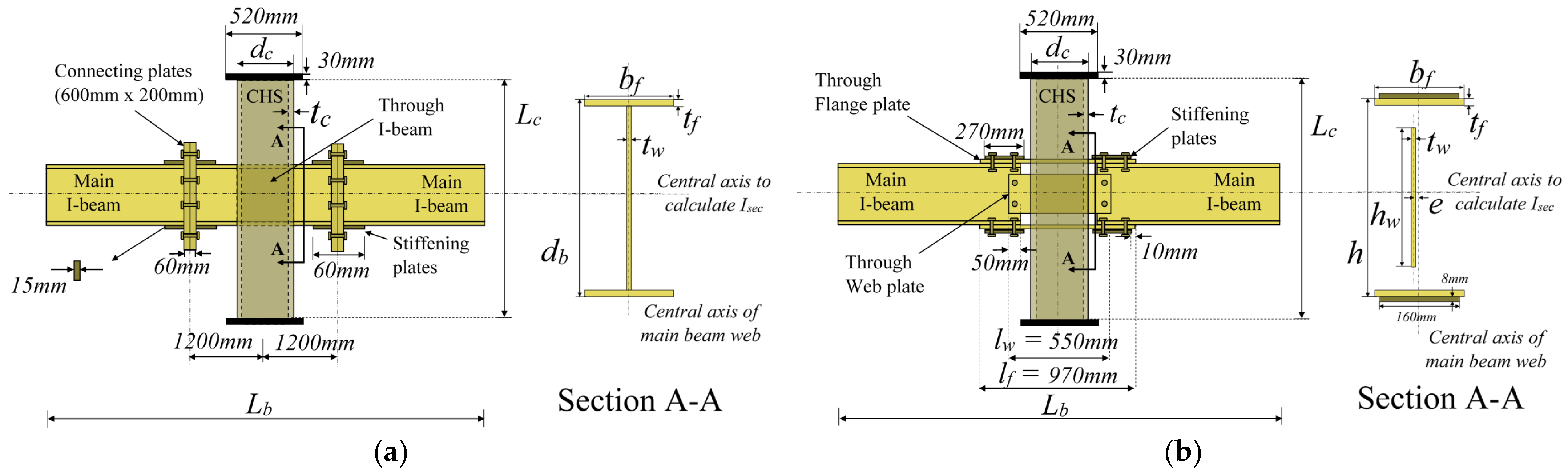
- LASTEICON C3 configuration (see Figure 3a): “main” or load-carrying I-beams connected to a CHS column using an I-section passing through the tube and end-plate splices;
- (2)
- LASTEICON C4 configuration (see Figure 3b): “main” or load-carrying I-beams connected to the CHS column using three steel plates passing through the tube and bolted connections.
2. Numerical and Experimental Investigations
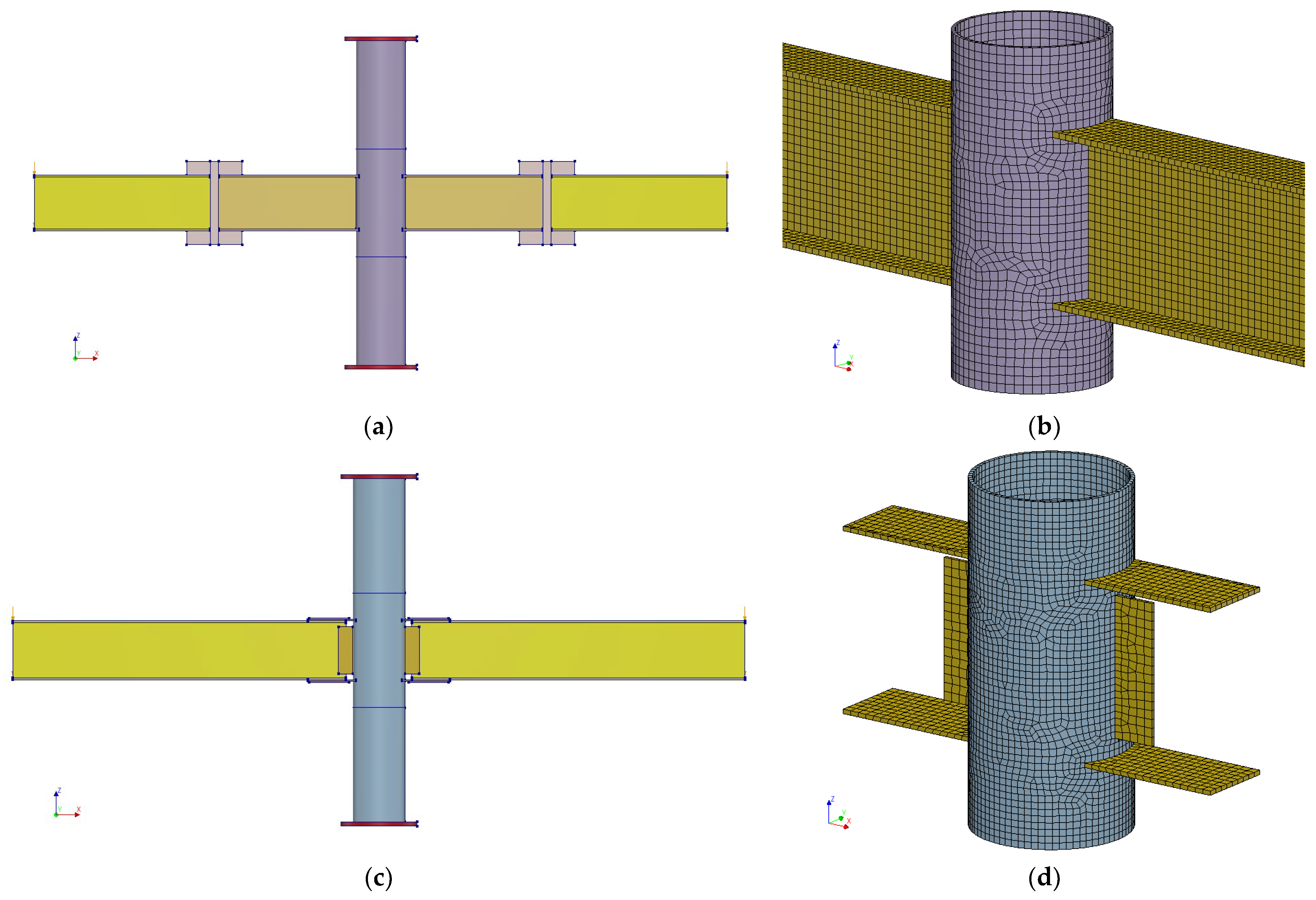
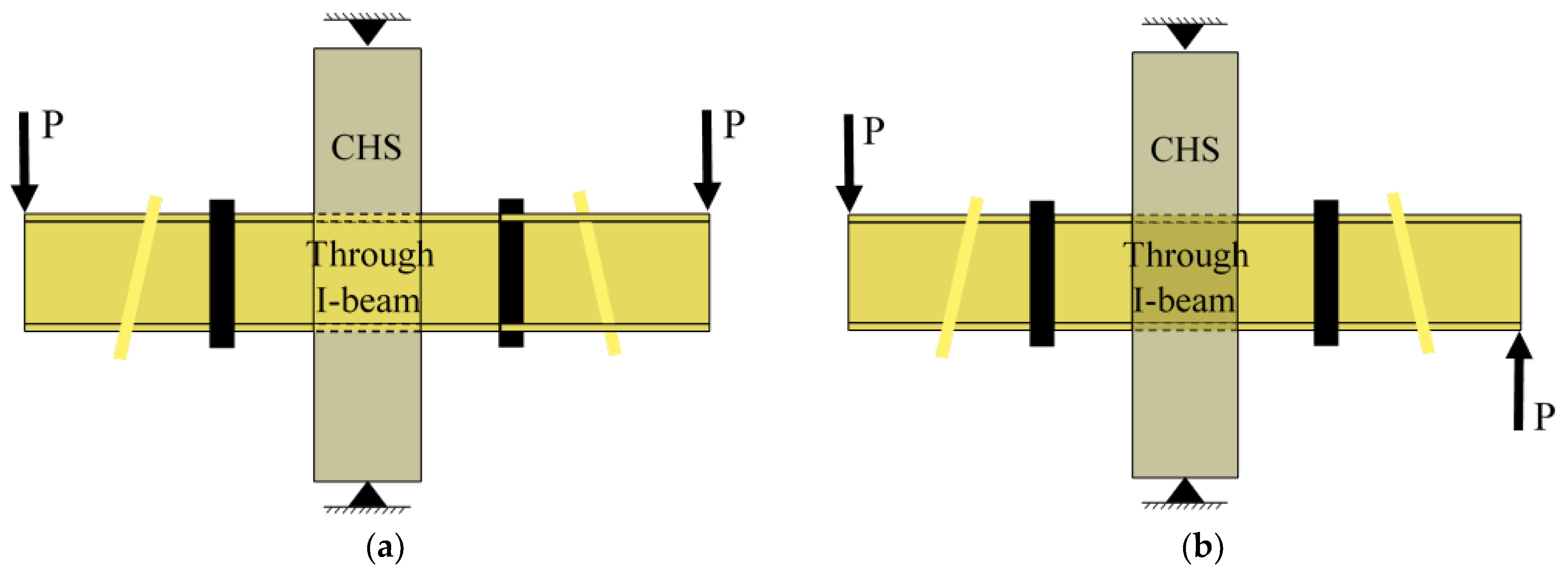
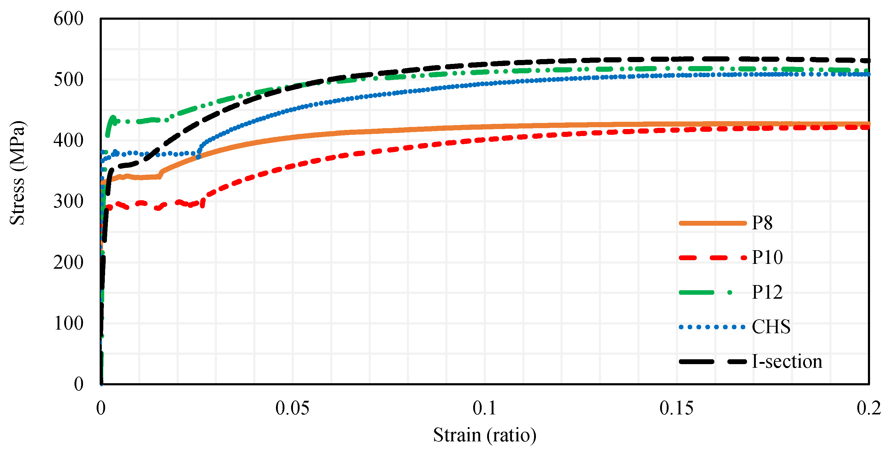
2.1. Modelling Approach, Load Cases, Boundary Conditions and Material Properties
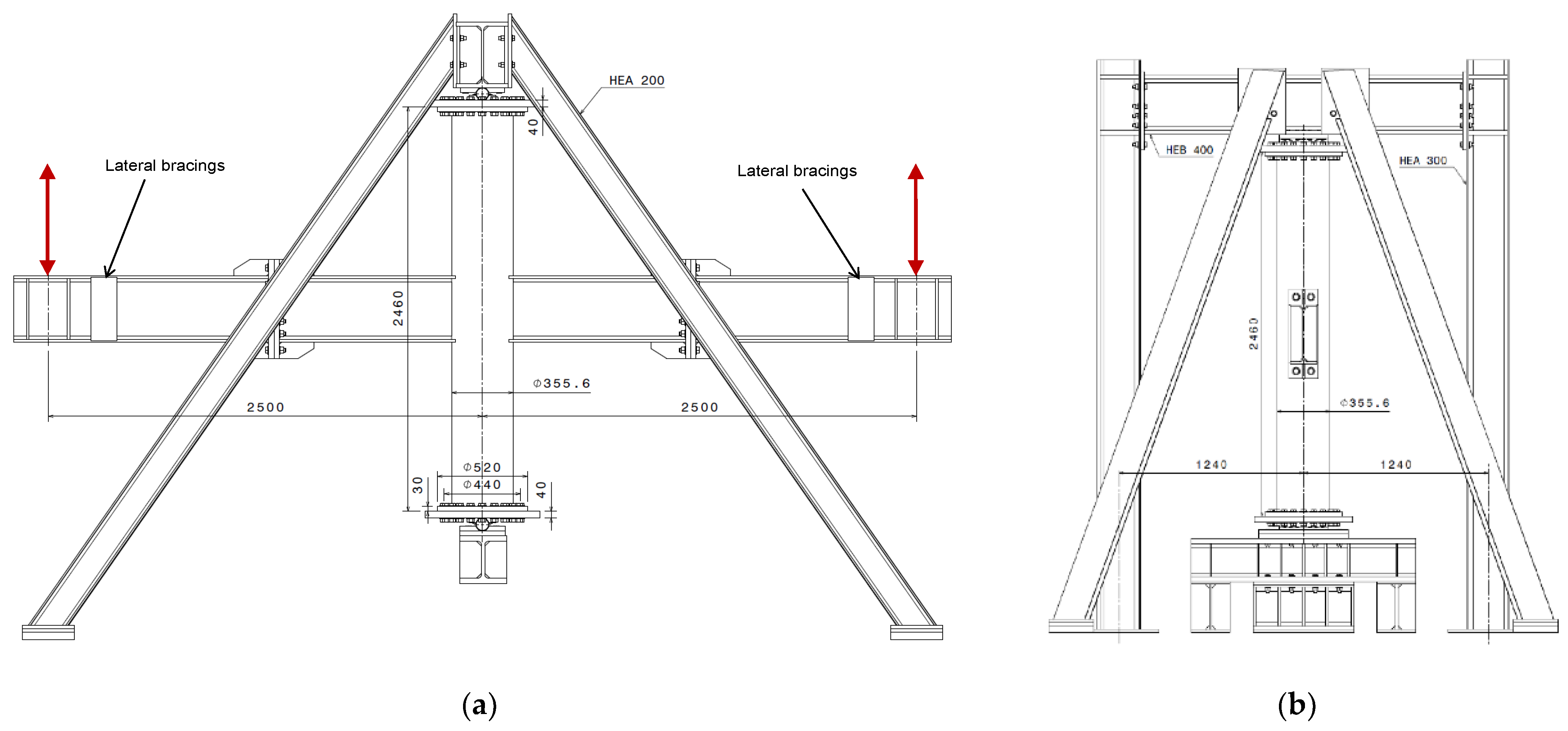
2.2. Experimental Test Set-Up and Load Application

2.3. Description of the Investigated Connections
2.3.1. Configuration C3
2.3.2. Configuration C4
3. Results and Discussions
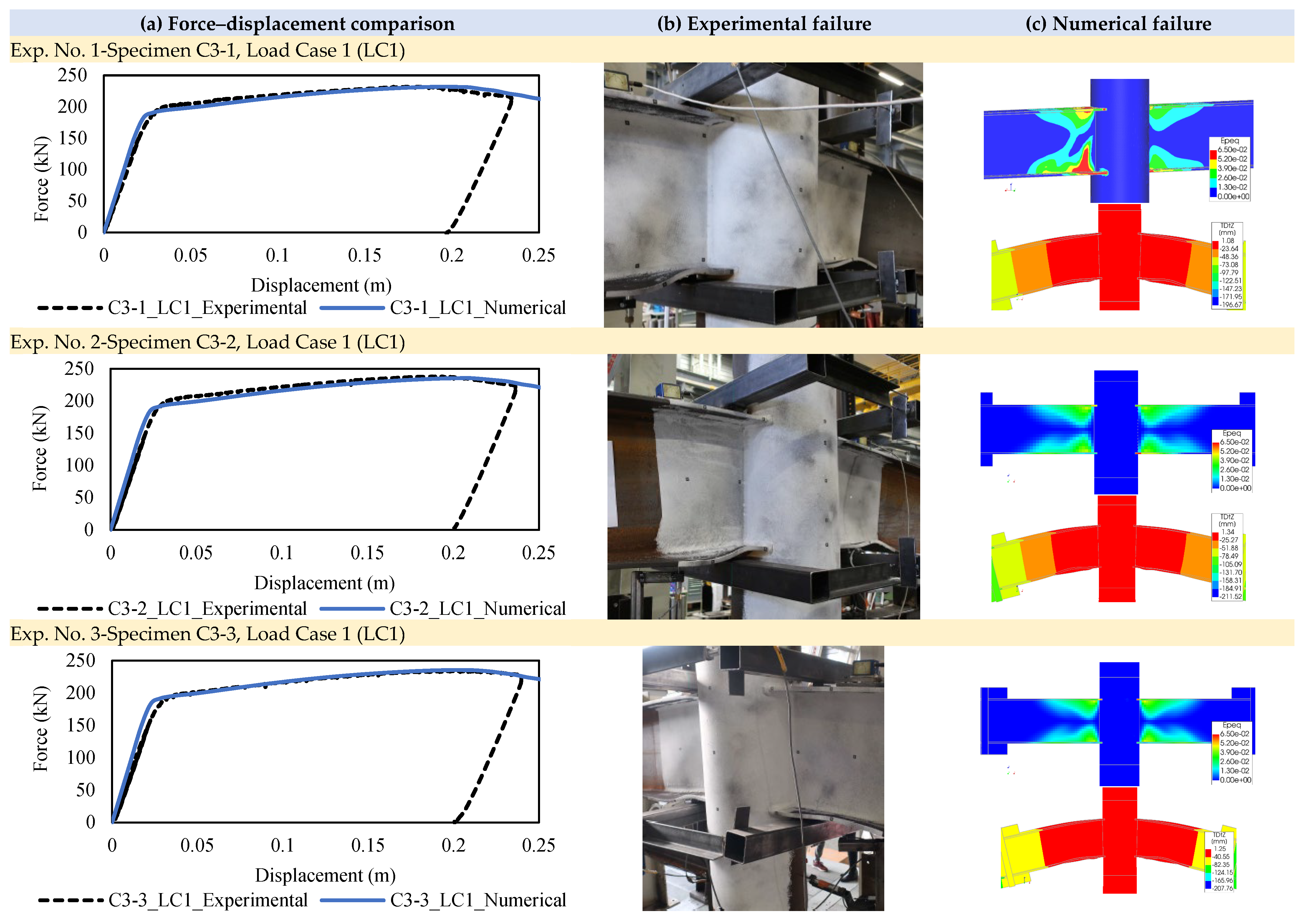
3.1. Configuration C3
3.1.1. LC1: Monotonic Gravitational Loading
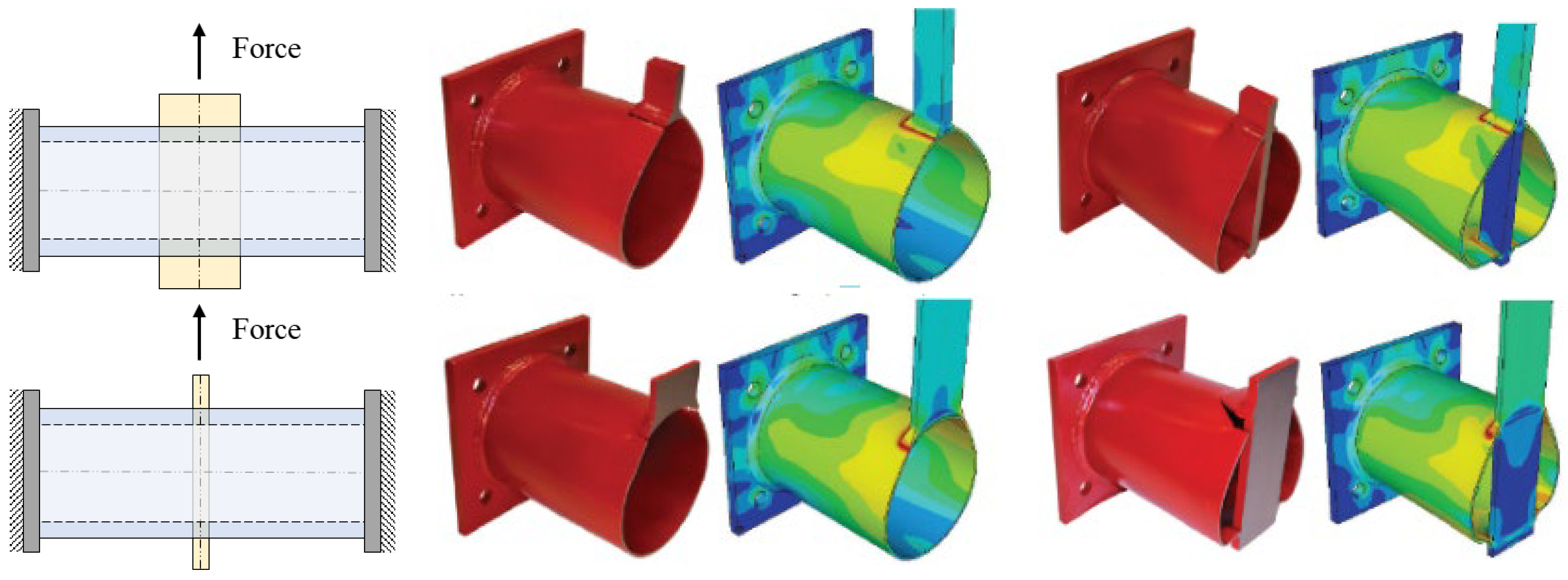
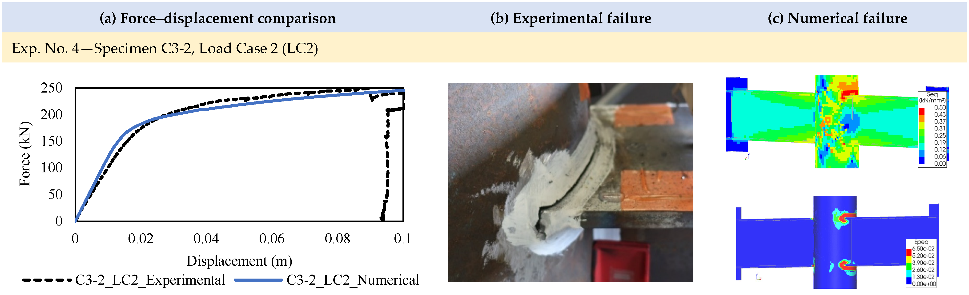
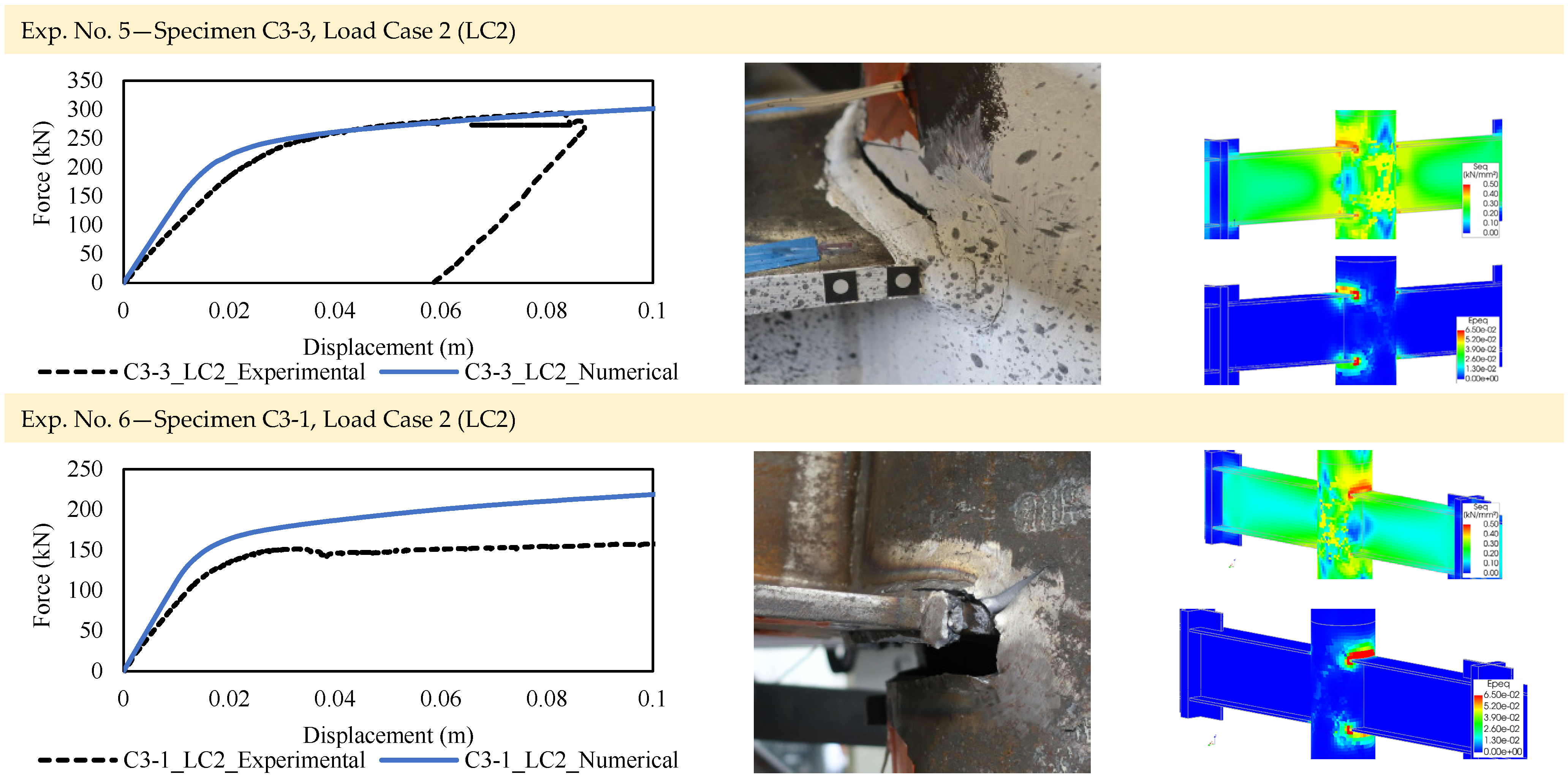
3.1.2. LC2: Monotonic Opposite Bending Loading
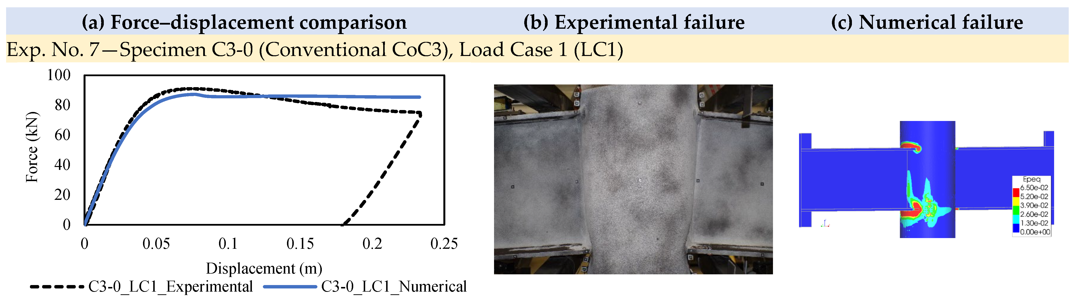
3.1.3. Comparison with a Conventional Connection, CoC3
3.2. Configuration C4
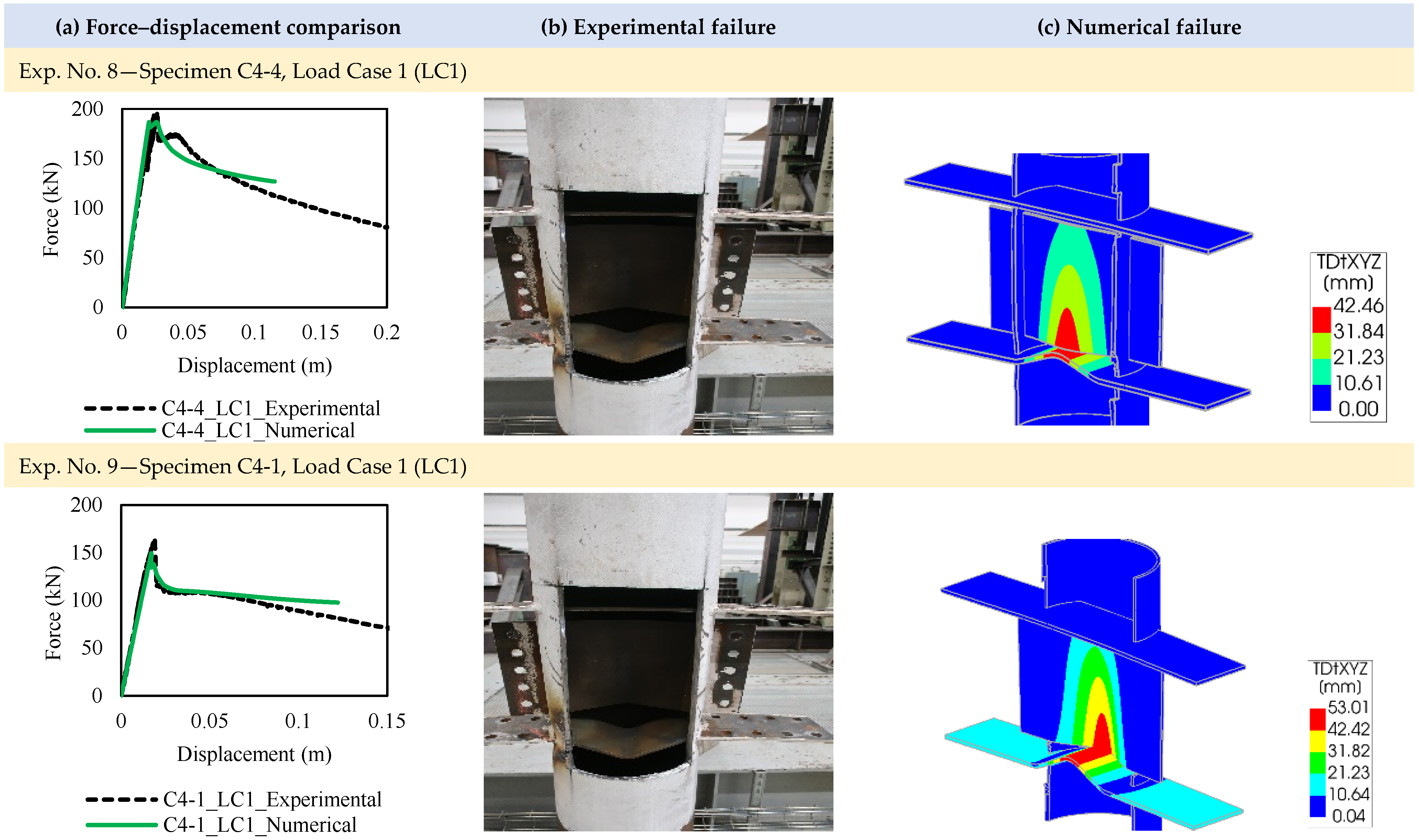
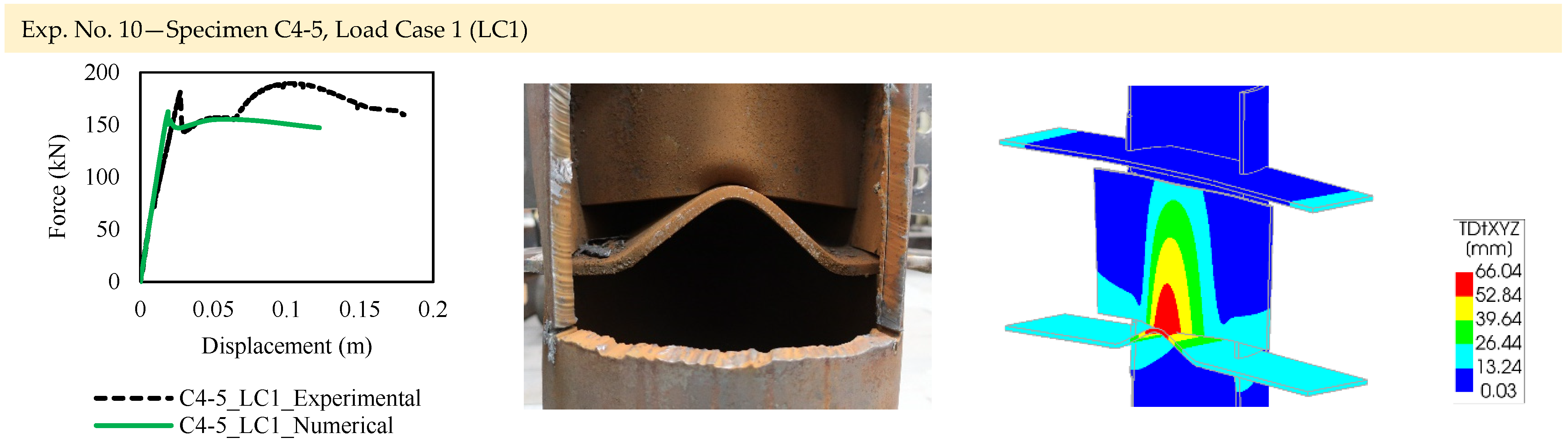
3.2.1. LC1: Monotonic Gravitational Loading
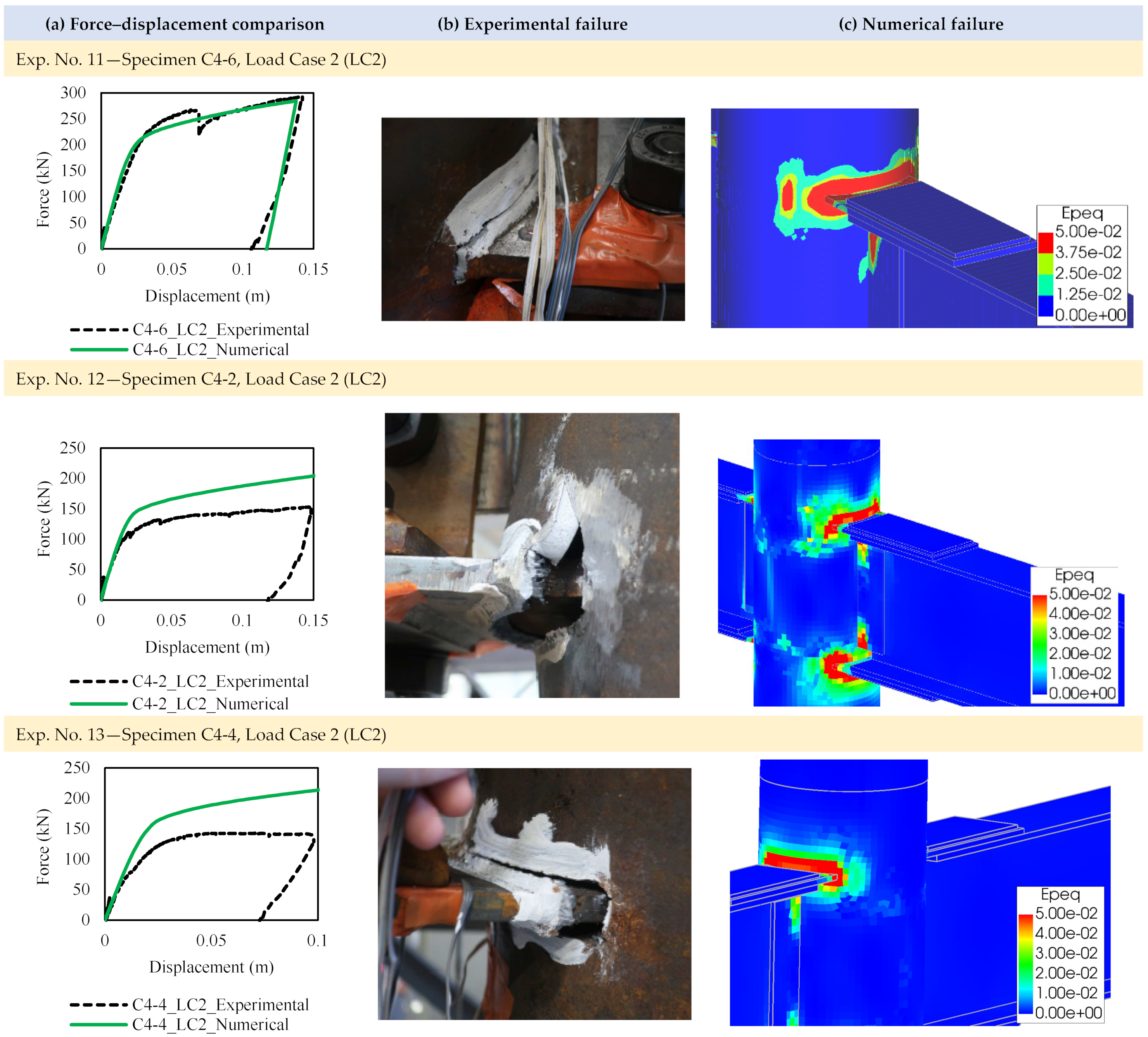
3.2.2. LC2: Monotonic Opposite Bending Loading
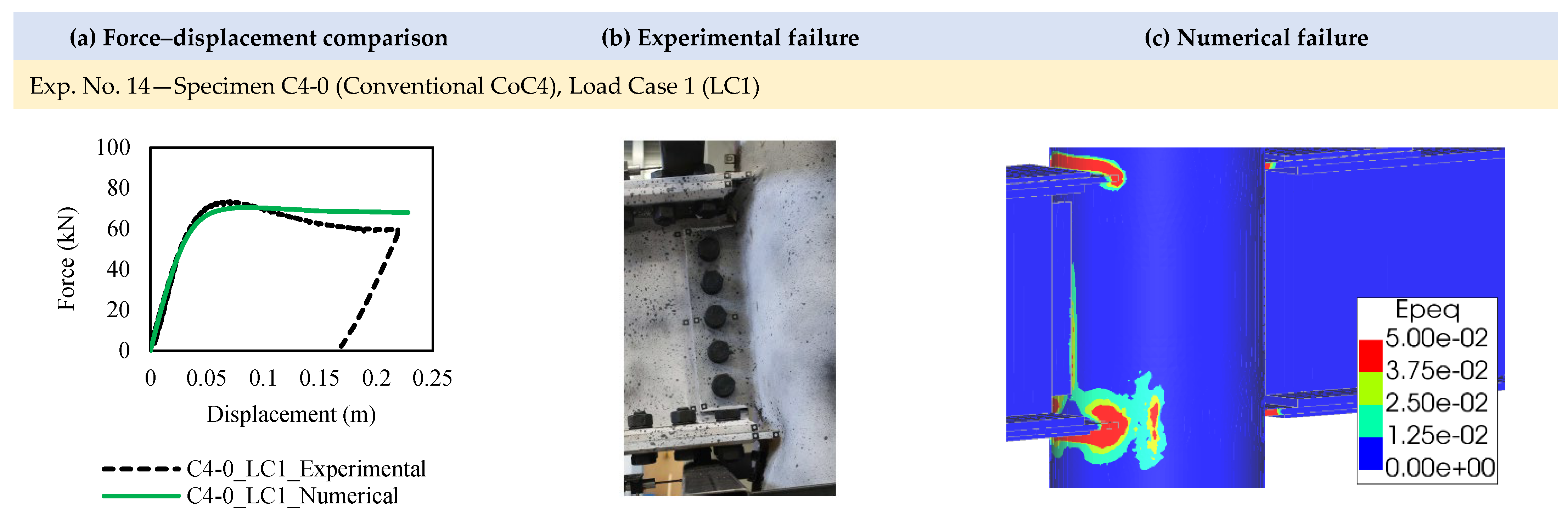
3.2.3. Comparison with a Conventional Connection, CoC4
4. Conclusions
Author Contributions
Funding
Data Availability Statement
Acknowledgments
Conflicts of Interest
References
- Wardenier, J.; Packer, J.A.; Zhao, X.L.; Van der Vegte, G.J. Hollow Sections in Structural Applications; CIDECT: Geneva, Switzerland, 2010. [Google Scholar]
- Wardenier, J.; Kurobane, Y.; Packer, J.A.; Van der Vegte, G.J.; Zhao, X.L. Design Guide for Circular Hollow Section (CHS) Joints under Predominantly Static Loading; CIDECT Design Guide 1; LSS Verlag: Dortmund, Germany, 2008. [Google Scholar]
- Bursi, O.S.; Ferrario, F.; Haller, M.; Lennon, T.; Bianco, L.; Mallardo, R.; Demonceau, J.-F.; Franssen, J.-M.; Jaspart, J.-P.; Hanus, F.; et al. Prefabricated Composite Beam-to-Column Filled Tube or Partially Reinforced-Concrete Encased Column Connections for Severe Seismic and Fire Loadings; RFSR-CT-2003-00034, Final Report; European Commission: Brussels, Luxembourg, 2009. [Google Scholar]
- Demonceau, J.F.; Hoang, V.L.; Jaspart, J.P. Performance-Based Approaches for High Strength Tubular Columns and Connections under Earthquake and Fire Loadings; RFSR CT-2008-00037, Final Report; European Commission: Brussels, Luxembourg, 2013. [Google Scholar]
- BLM Group. All in One Tube Technology No: 20, Inspired Tube; BLM Group: Ampthill, UK, 2015; Available online: https://www.blmgroup.com/all-in-one (accessed on 3 September 2023).
- De Winkel, G.D.; Puthli, R.S.; van Foeken, R.; Lu, L.H.; Rink, H.D.; Verheul, A.; Wardenier, J. Semi-Rigid Connections between I-Beams and Tubular Columns; Final Report, ECSC-EC-EAEC; European Commission: Brussels, Luxembourg, 1995. [Google Scholar]
- Rondal, J.; Würker, K.G.; Dutta, D.; Wardenier, J.; Yeomans, N. Structural Stability of Hollow Sections; CIDECT Design Guide 2; Verlag TÜV Rheinland: Cologne, Germany, 1992. [Google Scholar]
- Dutta, D.; Wardenier, J.; Yeomans, N.; Sakae, K.; Bucak, O.; Packer, J.A. Design Guide for Fabrication, Assembly and Erection of Hollow Section Structures; CIDECT Design Guide 7; Verlag TÜV Rheinland: Cologne, Germany, 1998. [Google Scholar]
- Kurobane, Y.; Packer, J.A.; Wardenier, J.; Yeomans, N. Design Guide for Structural Hollow Section Column Connections; CIDECT Design Guide 9; Verlag TÜV Rheinland: Cologne, Germany, 2004. [Google Scholar]
- Packer, J.A.; Sherman, D.R.; Lecce, M. Hollow Structural Section Connections; Steel Design Guide 24, Steel Design Guide Series; American Institute of Steel Construction: Chicago, IL, USA, 2010. [Google Scholar]
- Jaspart, J.P.; Weynand, K. Design of hollow section joints using the component method. In Tubular Structures XV, Proceedings of the 15th International Symposium of Tubular Structures (ISTS), Rio de Janeiro, Brazil, 27–29 May 2015; CRC Press: Boca Raton, FL, USA, 2015; pp. 405–410. [Google Scholar]
- Jaspart, J.P.; Pietrapertosa, C.; Weynand, K.; Busse, E.; Klinkhammer, R.; Grimault, J.P. Development of a Full Consistent Design Approach for Bolted and Welded Joints in Building Frames and Trusses between Steel Members Made of Hollow and/or Open Sections—Application of the Component Method, Volume 1—Practical Guidelines; CIDECT Report: 5BP-4/05; CIDECT: Aachen, Liege, 2005. [Google Scholar]
- Alostaz, Y.M.; Schneider, S.P. Connections to Concrete-Filled Steel Tubes; A Report on Research Sponsored by the National Science Foundation NSF CMS 93-00682; University of Illinois Urbana-Champaign: Champaign, IL, USA, 1996. [Google Scholar]
- Fukumoto, T.; Morita, K. Elastoplastic behavior of panel zone in steel beam-to-concrete filled steel tube column moment connections. ASCE J. Struct. Eng. 2005, 131, 1841–1853. [Google Scholar] [CrossRef]
- Nishiyama, I.; Fujimoto, T.; Fukumoto, T.; Yoshioka, K. Inelastic force-deformation response of joint shear panels in beam-column moment connections to concrete-filled tubes. ASCE J. Struct. Eng. 2004, 130, 244–252. [Google Scholar] [CrossRef]
- Morino, S.; Tsuda, K. Design and construction of concrete-filled steel tube column system in Japan. Earthq. Eng. Eng. Seismol. 2002, 4, 51–73. [Google Scholar]
- Fujimoto, T.; Inai, E.; Kai, M.; Mori, K.; Mori, O.; Nishiyama, I. Behavior of beam-to-column connection of CFT column system. In Proceedings of the 12th World Conference on Earthquake Engineering, Auckland, New Zealand, 30 January–4 February 2000; pp. 1–8. [Google Scholar]
- Alostaz, Y.M.; Schneider, S.P. Analytical behavior of connections to concrete-filled steel tubes. J. Constr. Steel Res. 1996, 40, 95–127. [Google Scholar] [CrossRef]
- Kosteski, N.; Packer, J.A. Experimental examination of branch plate-to-RHS member connection types. In Proceedings of the 9th International Symposium of Tubular Structures, Dusseldorf, Germany, 3–5 April 2001; pp. 135–144. [Google Scholar]
- Kosteski, N.; Packer, J.A. Longitudinal plate and through plate-to-hollow structural section welded connections. ASCE J. Struct. Eng. 2003, 129, 478–486. [Google Scholar] [CrossRef]
- Kosteski, N. Branch Plate to Rectangular Hollow Section Connections. Ph.D. Thesis, University of Toronto, Toronto, ON, Canada, 2001. [Google Scholar]
- Willibald, S.; Packer, J.A.; Voth, A.P.; Zhao, X. Through plate joints to elliptical and circular hollow sections. In Tubular Structures XI, Proceedings of the 11th International Symposium and IIW International Conference on Tubular Structures, Quebec City, QC, Canada; Routledge: London, UK, 2017; pp. 221–228. [Google Scholar]
- Zhao, X. Branch Plate Connections to Elliptical Hollow Sections. Master’s Thesis, University of Toronto, Toronto, ON, Canada, 2005. [Google Scholar]
- Mirghaderi, S.R.; Torabian, S.; Keshavarzi, F. I-beam to box-column connection by a vertical plate passing through the column. Eng. Struct. 2010, 32, 2034–2048. [Google Scholar] [CrossRef]
- Voth, A.P.; Packer, J.A. Branch Plate-to-Circular Hollow Structural Section Connections. I: Experimental Investigation and Finite-element Modeling. ASCE J. Struct. Eng. 2012, 138, 1007–1018. [Google Scholar] [CrossRef]
- Voth, A.P. Branch Plate-to-Circular Hollow Structural Section Connections. Ph.D. Thesis, University of Toronto, Toronto, ON, Canada, 2010. [Google Scholar]
- Di Benedetto, S.; Latour, M.; Rizzano, G. Chord failure resistance of 3D cut welded connections with CHS columns and through I-beams. Thin-Walled Struct. 2020, 154, 106821. [Google Scholar] [CrossRef]
- Di Benedetto, S.; Latour, M.; Rizzano, G. Assessment of the stiffness of 3D cut welded connections with CHS columns and through I-beams. Structures 2020, 27, 247–258. [Google Scholar] [CrossRef]
- Piscini, A. Passing-Through Tubular Column Joints for Steel and Composite Constructions Made by Laser Cutting Technology. Ph.D. Thesis, Università di Pisa, Pisa, Italy, 2019. [Google Scholar]
- Kanyilmaz, A. The problematic nature of steel hollow section joint fabrication, and a remedy using laser cutting technology: A review of research, applications, opportunities. Eng. Struct. 2019, 183, 1027–1048. [Google Scholar] [CrossRef]
- Kanyilmaz, A.; Castiglioni, C.A. Fabrication of laser cut I-beam-to-CHS-column steel joints with minimized welding. J. Constr. Steel Res. 2018, 146, 16–32. [Google Scholar] [CrossRef]
- Das, R.; Castiglioni, C.; Couchaux, M.; Hoffmeister, B.; Degee, H. Design and analysis of laser-cut based moment resisting passing-through I-beam-to-CHS column joints. J. Constr. Steel Res. 2020, 169, 106015. [Google Scholar] [CrossRef]
- Das, R.; Kanyilmaz, A.; Couchaux, M.; Hoffmeister, B.; Degee, H. Characterization of moment resisting I-beam to circular hollow section column connections resorting to passing-through plates. Eng. Struct. 2020, 210, 110356. [Google Scholar] [CrossRef]
- DIANA. DIANA User’s Manual, DIANA Release 10.2; DIANA FEA BV: Delft, The Netherlands, 2018; Available online: https://dianafea.com/ (accessed on 3 September 2023).
- Couchaux, M.; Castiglioni, C.; Hjiaj, M.; Wald, F. I-beam-to-CHS-column moment resisting joints using passing-through plates. J. Constr. Steel Res. 2021, 184, 106703. [Google Scholar] [CrossRef]
- Couchaux, M.; Vyhlas, V.; Kanyilmaz, A.; Hjiaj, M. Passing-through I-beam-to-CHS column joints made by laser cutting technology: Experimental tests and design model. J. Constr. Steel Res. 2021, 176, 106298. [Google Scholar] [CrossRef]
- Kanyilmaz, A.; Castiglioni, C.A.; Menghini, A. LASer Cutting Technology for Tubular Structures; Mid-Term Report, EU-RFCS Research Project; Grant Agreement Number 101034038; DABC: Milan, Italy, 2023. [Google Scholar]
- Safaeifaegh, S.; Zanon, G.; Bursi, O.S. Study of the behaviour of S355 welded joints with CHS columns and through beams. ce/Pap. —Proc. Civ. Eng. 2023, 6, 1513–1518. [Google Scholar] [CrossRef]
- Shamlooei, M.; Zanon, G.; Brugnolli, M.; Bursi, O.S. Study of the effects of laser cutting processes on S235 structural steel. ce/Pap. —Proc. Civ. Eng. 2023, 6, 2521–2526. [Google Scholar] [CrossRef]


| Config. Type | Load Case | Test No. | Specimen Name | Through Beam | CHS Dimensions | Welding Type | |
|---|---|---|---|---|---|---|---|
| dc (mm) | tc (mm) | ||||||
| LASTEICON C3 | LC1 | 1 | C3-1 | IPE 400 | 355.6 | 08.8 | Full penetration |
| LC1 | 2 | C3-2 | IPE 400 | 355.6 | 10.0 | Fillet | |
| LC1 | 3 | C3-3 | IPE 400 | 355.6 | 12.5 | Fillet | |
| LC2 | 4 | C3-2 | IPE 400 | 355.6 | 10.0 | Fillet | |
| LC2 | 5 | C3-3 | IPE 400 | 355.6 | 12.5 | Fillet | |
| LC2 | 6 | C3-1 | IPE 400 | 355.6 | 08.8 | Full penetration | |
| Conventional CoC3 | LC1 | 7 | C3-0 | IPE 400 | 355.6 | 10.0 | N.A. |
| Config. Type | Load Case | Test No. | Specimen Name | Through Plate(s) Dimensions | CHS Dimensions | Welding Type | |||||
|---|---|---|---|---|---|---|---|---|---|---|---|
| h (mm) | b (mm) | hw (mm) | tw (mm) | tf (mm) | dc (mm) | tc (mm) | |||||
| LASTEICON C4 | LC1 | 8 | C4-4 | 424 | 180 | 320 | 10.0 | 12.0 | 355.6 | 10.0 | Full penetration |
| LC1 | 9 | C4-1 | 424 | 180 | 320 | 08.0 | 10.0 | 355.6 | 08.8 | Full penetration | |
| LC1 | 10 | C4-5 | 424 | 180 | 320 | 08.0 | 10.0 | 355.6 | 12.5 | Fillet | |
| LC2 | 11 | C4-6 | 424 | 180 | 320 | 10.0 | 12.0 | 355.6 | 12.5 | Fillet | |
| LC2 | 12 | C4-2 | 424 | 180 | 320 | 10.0 | 12.0 | 355.6 | 08.8 | Full penetration | |
| LC2 | 13 | C4-4 | 424 | 180 | 320 | 10.0 | 12.0 | 355.6 | 10.0 | Full penetration | |
| Conventional CoC4 | LC1 | 14 | C4-0 | 424 | 180 | 320 | 08.0 | 10.0 | 355.6 | 8.8 | N.A. |
Disclaimer/Publisher’s Note: The statements, opinions and data contained in all publications are solely those of the individual author(s) and contributor(s) and not of MDPI and/or the editor(s). MDPI and/or the editor(s) disclaim responsibility for any injury to people or property resulting from any ideas, methods, instructions or products referred to in the content. |
© 2023 by the authors. Licensee MDPI, Basel, Switzerland. This article is an open access article distributed under the terms and conditions of the Creative Commons Attribution (CC BY) license (https://creativecommons.org/licenses/by/4.0/).
Share and Cite
Das, R.; Kanyilmaz, A.; Degee, H. Experimental Validation of Finite Element Models for Open-to-CHS Column Connections. Modelling 2023, 4, 454-469. https://doi.org/10.3390/modelling4040026
Das R, Kanyilmaz A, Degee H. Experimental Validation of Finite Element Models for Open-to-CHS Column Connections. Modelling. 2023; 4(4):454-469. https://doi.org/10.3390/modelling4040026
Chicago/Turabian StyleDas, Rajarshi, Alper Kanyilmaz, and Herve Degee. 2023. "Experimental Validation of Finite Element Models for Open-to-CHS Column Connections" Modelling 4, no. 4: 454-469. https://doi.org/10.3390/modelling4040026