Article

EMC of Inductive Automotive Charging Systems According to Standard SAE J2954

Institute of Power Transmission and High Voltage Technology, University of Stuttgart, Pfaffenwaldring 47, 70569 Stuttgart, Germany
*
Author to whom correspondence should be addressed.
Vehicles 2023, 5(4), 1532-1552; https://doi.org/10.3390/vehicles5040083
Submission received: 30 August 2023 / Revised: 21 September 2023 / Accepted: 26 October 2023 / Published: 28 October 2023
(This article belongs to the Special Issue Wireless Electric Vehicle Charging)

Abstract

:
To increase the acceptance of electric vehicles (EVs), inductive charging technology can be an important tool because of the simplified charging process for the user. This paper presents the fundamentals of wireless power transfer (WPT) for EVs, while focusing on electromagnetic compatibility (EMC). This work deals with the investigation of the conducted and field-bound interference emissions using a WPT system with a max. input power of 3.6   k W . During the research, a new frequency-tracking algorithm is developed, to find the optimal operating frequency at any coil misalignment. The impedance behavior as well as the possible interference paths are investigated, showing the great geometric influence of the test bench setup. The conducted interference currents are analyzed and subsequently filtered. The filter shows good performance in attenuating common mode currents. The measured radiated magnetic field is directly rated against the proposed limits of various standards. Finally, the EMC influence of the direct current (DC) power supply line to the inverter is examined, which is not defined precisely in the standard. This underlines the significance of a standardized test setup, since the limit values can be met under different geometric circumstances of the DC cable.

1. Introduction

The charging of electric vehicles (EVs) is usually carried out conductively, i.e., wired. However, uncomfortable handling and vandalism represent major challenges for the breakthrough of electromobility. Furthermore, environmental influences such as rain, ice or darkness could make it difficult to use a charging station. These are all reasons why the wireless, inductive charging of electric vehicles can increase the popularity of EVs. In particular, the high comfort gain for the user has a significant part in its possible future success. Wireless charging makes it possible to automate the charging process so that the battery can be charged automatically at any time, for example in parking lots, in front of traffic lights or on selected sections of road. Moreover, it is possible to implement a dynamic charging process [1,2], that enables the continuous supply of electricity to a moving vehicle.
Simply speaking, inductive energy transmission functions like a loosely coupled transformer with a large air gap. The key challenges in the contactless charging of EVs are thus overcoming the vehicle-dependent air gap and the parking-related position tolerance. The resulting low and position-dependent magnetic coupling between the coils causes a much higher reactive power to be fed into the system. This has a negative effect on the efficiency and on the power factor. Furthermore, high magnetic field strengths are generated during inductive charging, resulting in challenges considering the electromagnetic compatibility (EMC). In addition to the magnetic field in the intended operating spectrum, there are other interference emissions due to leakage fields. These fields do not contribute to energy transfer. Instead, the leakage field can cause unwanted electric and magnetic fields (EMF) and electromagnetic interference (EMI). The inverter, which is positioned in the charging station and generates the high-frequency AC voltage for the ground coil, also generates significant interference currents at the same time due to the high switching frequency. These include the differential mode (DM) current, as well as the common mode (CM) current, both of which can generate significant time-varying magnetic fields in the surrounding environment. The investigation of these interference currents is therefore an important aspect in the EMC characterization of inductive automotive charging systems. For this reason and to ensure that the emission of the resulting harmonics do not reach the spectrum of broadcasting services, suitable standards and limits must be defined for the design of WPT systems and their radiated fields. The interference levels can also affect other sensitive systems in a car, such as PEPS (passive entry passive start), whose operating frequency is 125   kHz [3]. Currently, there are no harmonized international limits for the radiated H field of WPT systems in the frequency range between 9   kHz and 30   MHz .
In the recent years, many standardization committees have given proposals for the general requirements, emission test methods and limit requirements for WPT systems. The authors of [4,5,6,7,8] provide a summary of the outcome. The conducted interference emissions of WPT systems are dealt with in detail in [9,10,11,12,13,14]. The authors of [13,14,15,16,17] deal with the field-bound interference emissions. In [18], the magnetic field was measured and compared in different test environments, such as in EMC chamber and in open area. In [19], a passive impedance network for EV batteries was developed, to investigate the differences between a resistive load, which is usually used for EMC measurements.
The following work deals with the conducted and field-bound interference emissions of a WPT system, with a max. input power of 3.6   k W . For this purpose, an existing prototype is investigated, whose design and description was introduced in [14,15,20]. The system is based on the SAE J2954 standard [21], which suggests a frequency operating range from 79   kHz to 90   kHz . In the beginning of this article, the basics of the air-coupled transformer and resonant inductive energy transfer are discussed, considering a system based on LCC-SP compensation. Afterwards, a new frequency-tracking algorithm, which can track the optimal operating frequency of the WPT system without the common use of sensors and microcontrollers, is presented. Subsequently, the actual standardization committees for WPT systems are introduced. The investigation of the impedance behavior as well as the possible interference paths are also part of the research, explaining the geometric influence of the test bench setup. The conducted interference currents are analyzed at different measurement points on the WPT system, unlike in the presented research articles, where measurements are always taken at the same measuring point, e.g., between the inverter and ground coil. This allows a conclusion to be made on the optimal position of a filter. The design of a suitable filter, which is able to carry the nominal input power, is also discussed as part of this work. The result of the measured radiated magnetic field is presented, which is performed by an active loop antenna. In comparison to the previously presented articles, the results are directly rated against the proposed limits of SAE and CISPR 11 (CIS/B/687/CDV) [22]. Finally, the EMC influence of the supply line to the inverter is examined, which is not defined more precisely in the standard or in other research articles. The results of all measurements are then critically analyzed and summarized.

2. Fundamentals of Wireless Electric Vehicle Charging

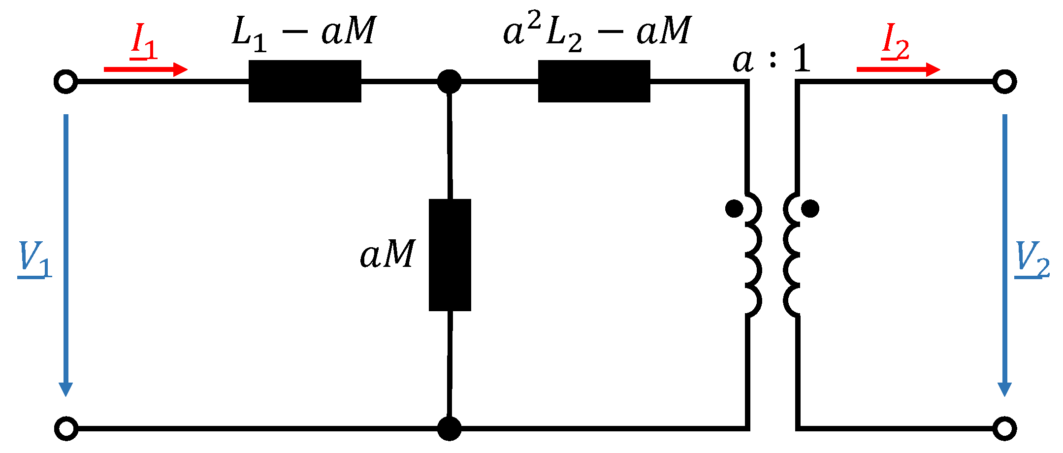
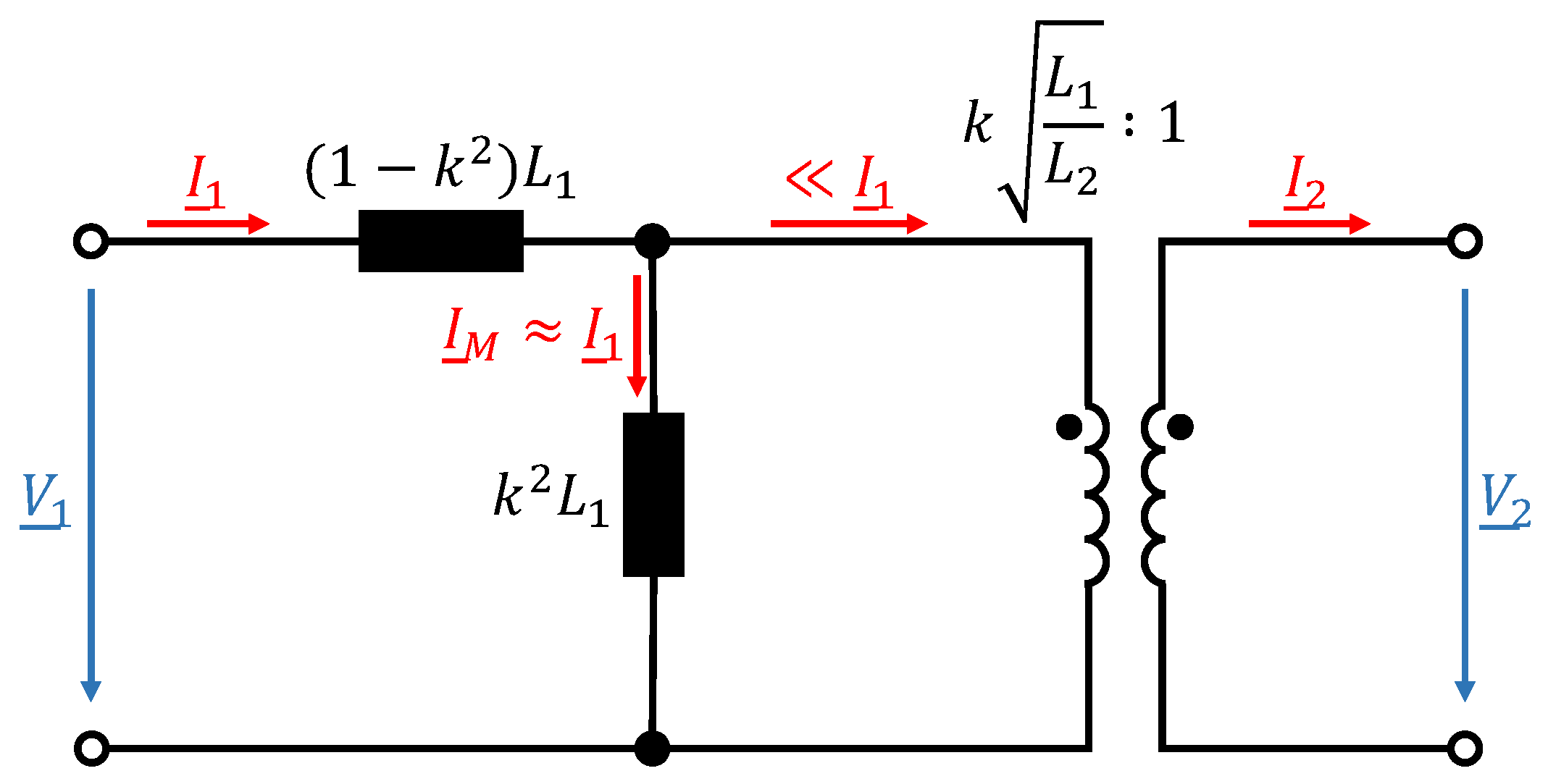
2.1. Lossless Air-Core Transformer

To understand the EMC challenges of wireless electric vehicle charging, this section presents the fundamentals of an air-coupled transformer. For the sake of simplicity, a lossless transformer is assumed. Except for the leakage flux, all other losses are neglected, e.g., copper losses of primary and secondary winding. Due to coil misalignment and the distance between two coils, it is not possible to achieve an ideal magnetic coupling in general. This means that the coupling factor k is always less than 1. For air-coupled systems, typical coupling factors are in the range of k < 0.5 [23]. The magnetic flux that passes through only one of the two coils due to the leakage inductance is the leakage flux. Under the assumption that
M = k · L 1 L 2
where M represents the mutual inductance between the coils, the equivalent M-model of a lossless transformer considering the leakage flux is depicted in Figure 1.
L 1 and L 2 represent the self-inductance of primary (transmitter) and secondary (receiver) coil, while a represents the equivalent turns ratio of the coils. The longitudinal inductances represent leakage inductances and the transverse inductance the main inductance which carries the no-load magnetizing current I ̲ M . By choosing the turns ratio to a = k L 1 / L 2 , the secondary leakage inductance can be neglected [24]. This results in a simplified equivalent circuit of the lossless transformer which is depicted in Figure 2.
For small coupling factors the majority of the input current does flow as magnetizing current through the main inductance. The result is a phase shift between the input current and the input voltage and thus a high inductive reactive power consumption. Furthermore, in WPT systems the impedance of the secondary side Z ̲ s e c reflected on the primary side is defined as [24]:
Z ̲ r = ( M ω ) 2 Z ̲ s e c = ( k · L 1 L 2 · ω ) 2 Z ̲ s e c
In addition to the higher leakage flux, it can be seen that small coupling factors also have major impacts on electrical magnitudes of the circuit.

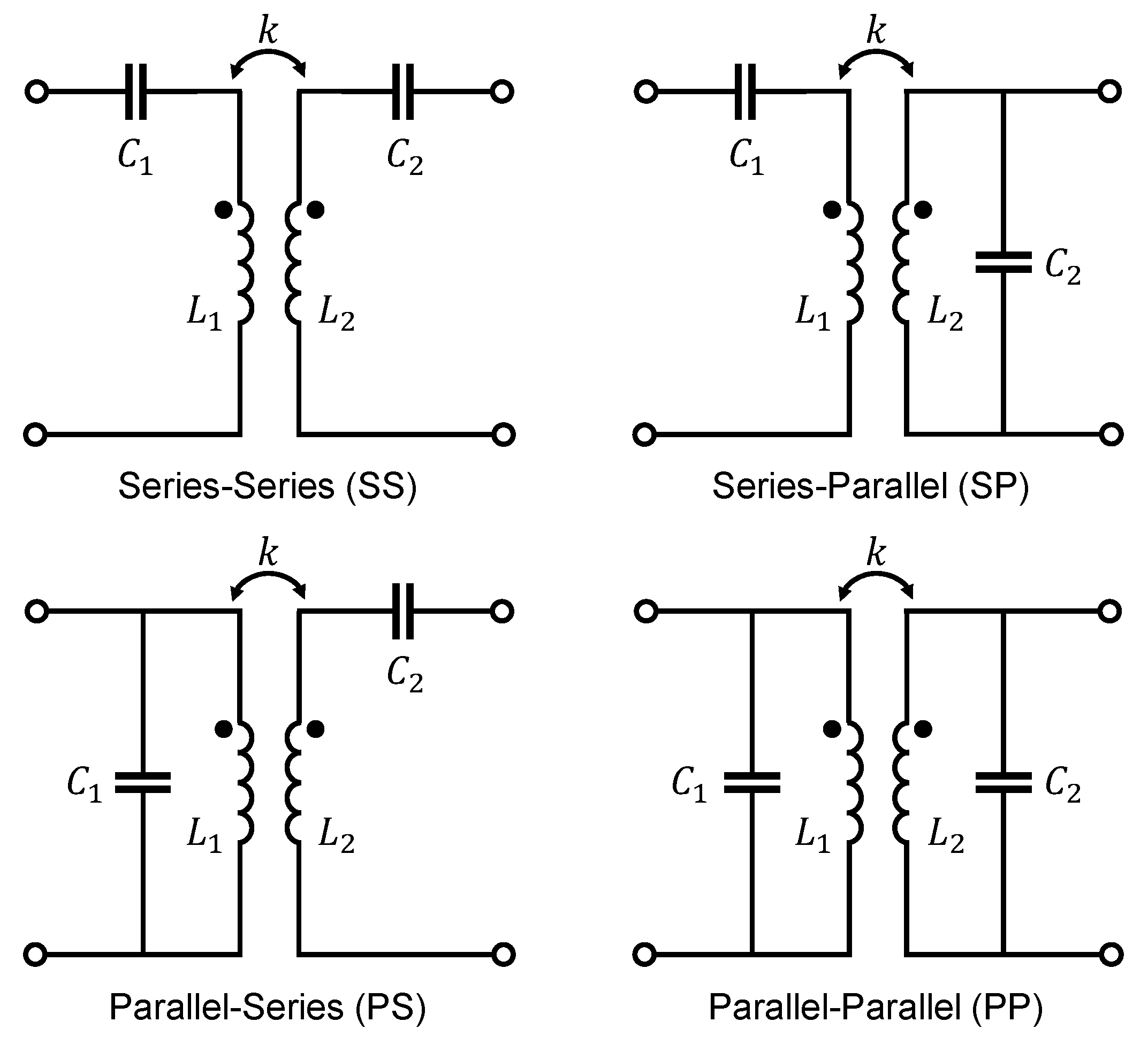
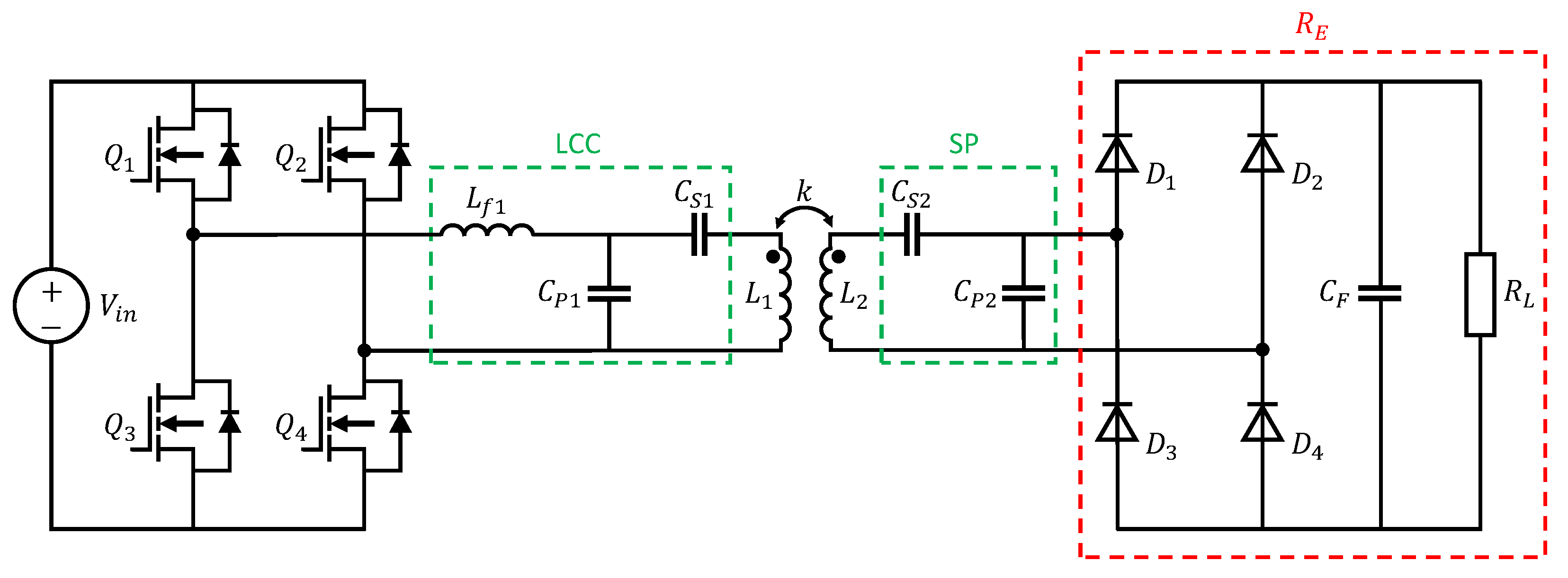
2.2. Resonant Inductive Wireless Power Transfer

In order to improve the performance of WPT systems and thus achieve the highest possible efficiency despite small coupling factors, a reactive power compensation is required. That means that the overall impedance of the system at its terminal connection to the power source is only ohmic. The simplest way to counteract inductive reactive power is to generate capacitive reactive power by using capacitors. So the goal is to develop a compensation circuit that cancels the high-leakage inductances with the aid of compensation capacitors. The challenge of designing a suitable compensation circuit is that there could be significant frequency or phase shifts due to the changing load on the vehicle side [25].
In a traditional transformer with a ferromagnetic core where the coupling factor is in the range of k > 0.5 , the compensation capacitance should resonate with the leakage inductance [23]. Whereas in an air-coupled system with k < 0.5 , the compensation capacitors should be resonant with the self-inductances of the primary or secondary coil [23]. The compensation circuit on the primary side is used to minimize the volt-ampere (VA) rating of the power supply and to achieve zero-phase-angle (ZPA) operation by minimizing the reactive part of the reflected impedance from the secodary side [23,25,26,27,28,29]. The compensation circuit on the secondary side tunes the circuit to have the same resonant frequency as the transmitter side to maximize power transfer [25,26,27,28,29]. The four basic compensation topologies were fundamentally analyzed in [28,29,30,31,32,33] and are depicted in Figure 3.
Among the four basic compensation topologies, SS and SP have become the most widely used in practice [25,29,32,34]. This is mainly because WPT systems are fed with square wave voltages and, therefore, using a parallel compensation capacitor on the primary side would lead to very high transfer currents, since the capacitor is fed directly from the source. This would greatly affect the lifespan of the capacitor [34]. Furthermore, the required capacitance of primary side parallel-compensated topologies (PP and PS) become dependent on both the magnetic coupling and the load, which makes it inconvenient to achieve ZPA on the primary side [25,31]. According to [25,29,31], for the SS topology the required primary capacitance is independent of the mutual inductance as well as of the load, whereas in the SP topology, the primary capacitance is affected by mutual coupling. This makes the SS compensation circuit the commonly most used one. However, it is important to note that in topologies with series primary compensation, the current increases very sharply when k is changing due to misalignment, which leads to an unsafe behaviour of the power supply [30]. Topologies with parallel primary compensation are safe for the power supply in the absence of the secondary coil but are unable to transfer requested power if misalignment occurs [30].
In addition to the previously mentioned advantages, compensation topologies help to realize soft switching via zero-voltage switching (ZVS) or zero-current switching (ZCS) of power transistors in the inverter and thus help to reduce switching losses [23,26,27]. Another benefit of using compensation topologies is that constant current or constant voltage charging can be achieved, which leads to the fact that a load-independent operation without a control circuit can be realized [23,26,27]. This implies that either the output DC current at the battery or the DC voltage is fixed, which is a highly desirable trait in EV battery charging. For a deeper insight into this topic, please refer to the further literature [35,36].
In summary, it can be said that the problem with using basic compensation topologies for WPT systems is that performance and efficiency are very dependent on coil misalignment [32,37]. High-order compensation topologies that contain more than one reactive component provide better overall performance under these circumstances [32,37]. The higher misalignment tolerance of the coils is an important aspect, especially from an EMC point of view, as this has a major influence on the magnetic leakage flux. In addition, there are other advantages such as low output voltage variation, reduced bifurcation phenomenon, higher design freedom and high efficiency for dynamic charging applications [32,37].
As part of the practical EMC investigations in the coming sections, a high-order LCC-SP compensation topology is used. This topology was developed in a previous work at the institute [14] and is shown in Figure 4. Detailed descriptions of this topology are carried out by [38,39].
Q 1 Q 4 are four power SiC-MOSFETs on the primary side which together form the full-bridge inverter. This is the most common topology because it achieves good efficiency and allows ease of control [40]. The appropriate switches must be selected according to the power requirement and operating frequency of the WPT system. Apart from higher costs, using MOSFETs offers a lower on-state resistance compared to Si-IGBTs, allowing higher switching frequencies, higher power transfer and a reduction of losses and cooling requirements [37,40,41]. The advantages of square wave over pure sine wave inverters are reduced complexity, fewer components, lower switching losses and lower production costs [42]. Furthermore, it is possible to achieve higher overall WPT system efficiency due to the higher efficiency of square wave inverters [42]. The disadvantage of square wave voltages is the high number of harmonics in the frequency spectrum, which leads to EMC challenges [42].
To avoid further high-frequency switching interference, the rectifier in front of the battery ( D 1 D 4 ) is set up as a passive diode bridge rectifier. A better overall transfer efficiency and a reduction of harmonic components of radiation noise may be achieved using active rectifiers [43,44]. Due to safety reasons and reduced complexity, constant passive loads are used in EMC component tests instead of real batteries [14]. The circuit of the diode rectifier, filter capacitor C F and resistive load R L can be replaced by their equivalent resistance R E , which illustrates the resistance to use for loading the resonant circuit when using an AC analysis and is defined as [45,46]:
R E = 8 R L π 2
According to [32], the main advantage of the LCC-SP compensation is that it has the most tolerance with misalignment in terms of efficiency. Especially for the radiated emissions of a WPT system this is a great benefit. The disadvantage of this topology is that it is not safe for operation at low-load conditions and in the absence of the secondary coil due to the excessive no-load voltage in the primary coil [32]. However, since this work involves a stationary inductive charging system this disadvantage is acceptable. L f 1 , C P 1 and C S 1 are the compensation components on the primary side while C S 2 and C P 2 are on the secondary side of the WPT system. The circuit parameters are designed to satisfy the resonance relationship as follows
j ω 0 L 1 + 1 j ω 0 C S 1 + 1 j ω 0 C P 1 = 0
j ω 0 L f 1 + 1 j ω 0 C P 1 = 0
j ω 0 L 2 + 1 j ω 0 C S 2 + 1 j ω 0 C P 2 = 0
where ω 0 is the resonant angular frequency. Under resonance the LCC-SP compensation shows a constant current output (CCO) characteristic [39]. The specifications of the WPT system are shown in Table 1.
The input impedance magnitude and angle of the designed LCC-SP compensation circuit is simulated using an AC analysis in SPICE and is depicted in Figure 5.
It can be seen that the input impedance of the high-order harmonics is much larger than that of the resonant frequency ( 80.45   kHz ), where the phase angle is ϕ = 0 . This results in lower current harmonics through the primary coil L 1 , contributing to a nearly ideal sinusoidal output current waveform of the inverter [39].

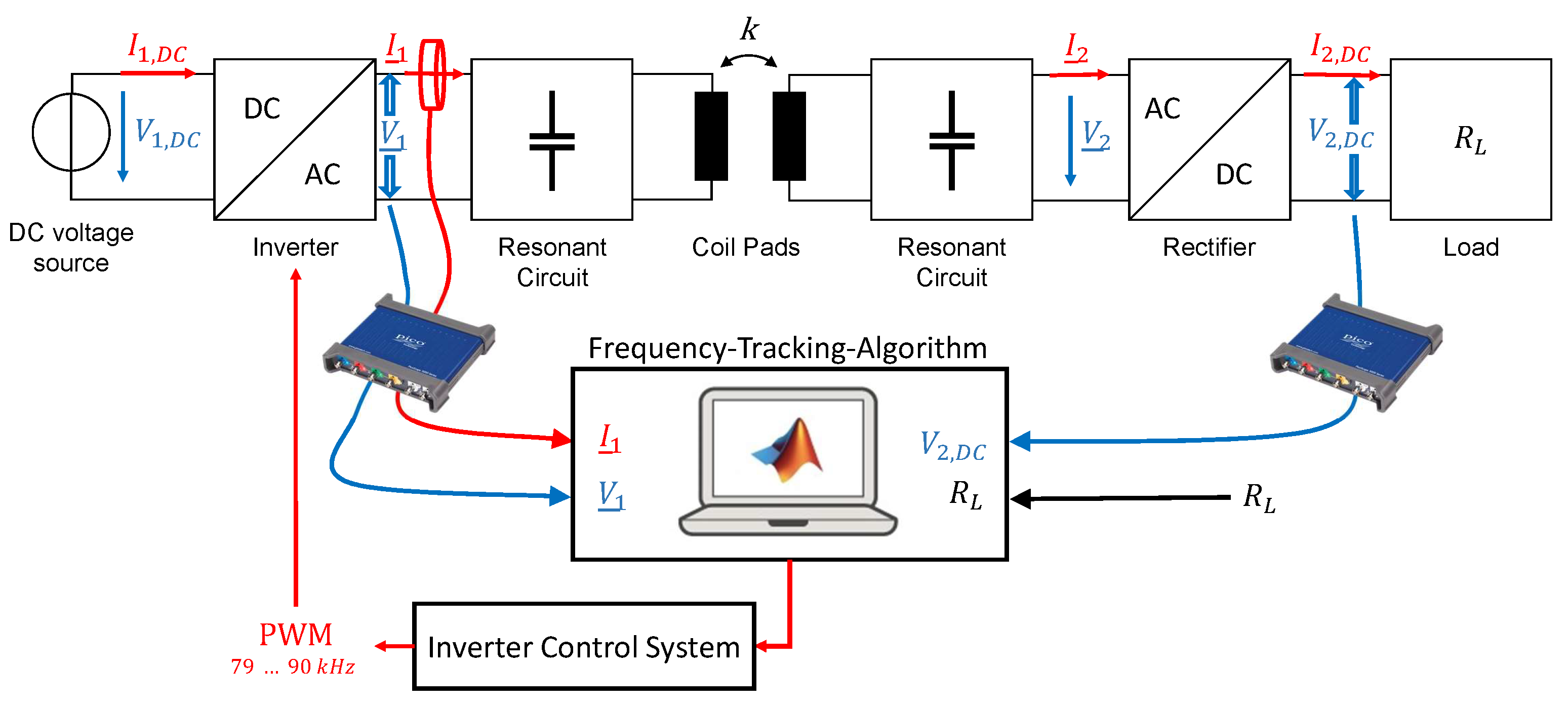
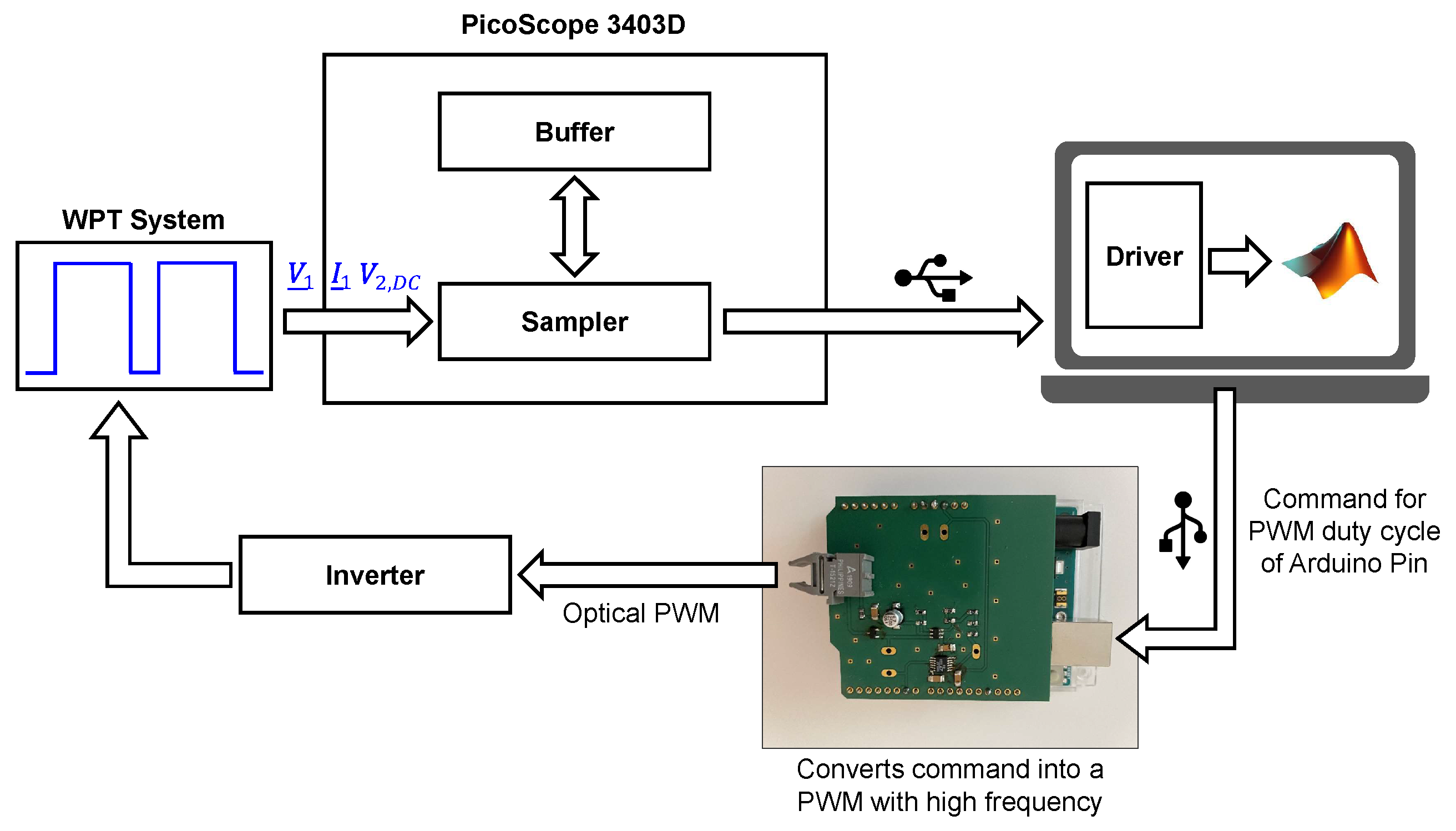
3. Frequency Tracking Algorithm

One goal of this work is to find a way to obtain the optimal operating frequency for any coil misalignment of the existing WPT system without using additional current and voltage sensors. This offers the advantage that the existing PCBs do not have to be modified and no additional microcontroller is required. By measuring current and voltage, it is possible to calculate the active power at the resistive load as well as the reactive power at the inverter output. With the phase angle, the active power at the inverter output and therefore the efficiency of the WPT system can be determined. Furthermore, with the help of the phase angle, the operating state can be identified when the MOSFETs are operated in ZVS, which minimizes the switching losses. This allows the optimum operating frequency to be found, achieving the highest efficiency. The necessary electrical values to be measured are:
  • Inverter output current I 1 ;
  • Inverter output voltage V 1 ;
  • Output voltage at the load V 2 , D C (constant load).
For this purpose, the measurements are made with an USB oscilloscope and are recorded and evaluated directly in Matlab. The sampling rate is 125 MS/s and the measured values are transferred directly to the PC via USB cable. The USB oscilloscope has a vertical resolution of 8 bits and a bandwidth of 50   MHz . Figure 6 shows the schematic structure of the entire WPT system with the previously described frequency-tracking process.
The main component of the inverter control system is an Arduino Uno, which has several PWM pins and an USB interface, which can be used to communicate with Matlab. Thus, the command for generating an electrical PWM signal can also be transferred directly with Matlab. With the help of several ICs on the PCB, a variable PWM in the frequency range from 79   kHz to 90   kHz can be generated. Finally, the PWM signal is transmitted to the inverter via optical data transmission. The entire signal flow chain is illustrated in Figure 7.
For a given positioning of the secondary coil over the primary coil, the system will sweep through the frequencies from 79   kHz to 90   kHz with a frequency step size of approximately 50   Hz . For each frequency, the values of current and voltage are measured to calculate the corresponding active powers. Subsequently, the max. efficiency and thus the optimum operating frequency can be found.

4. Investigation of the Conducted and Field-Bound Interference Emissions

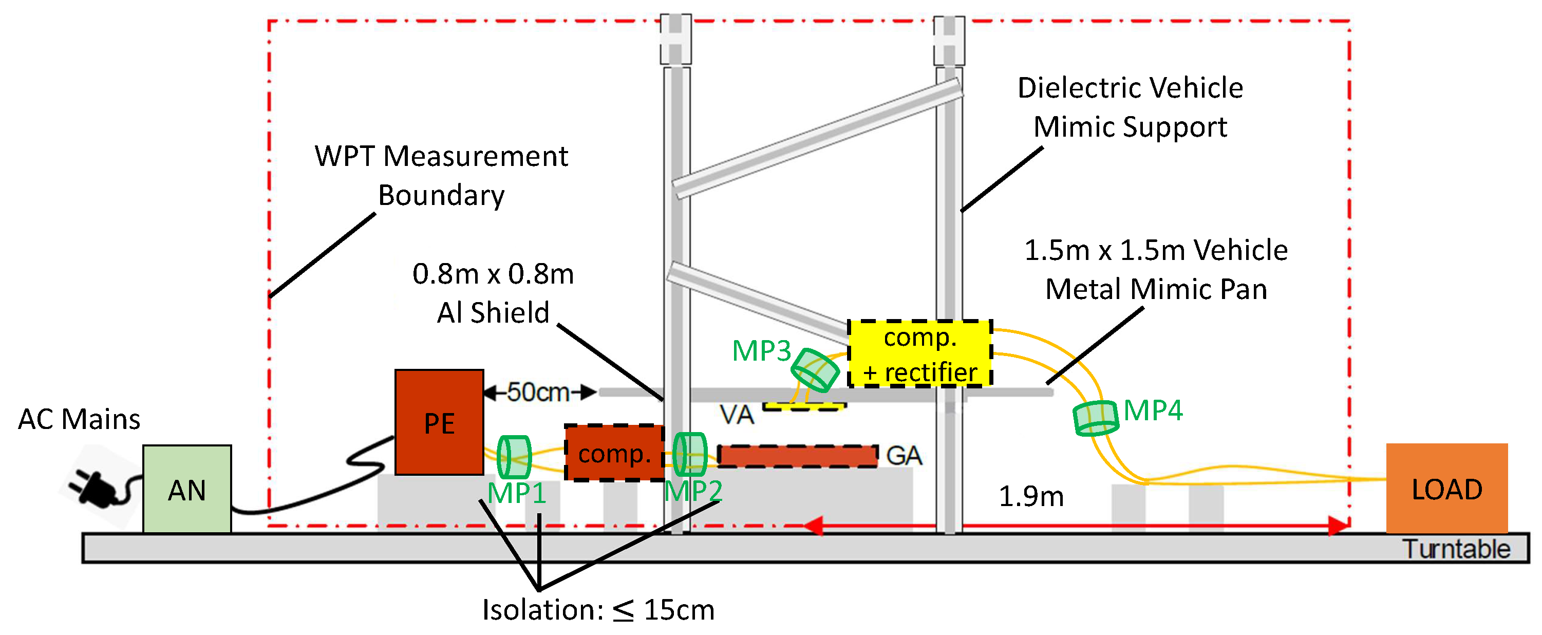
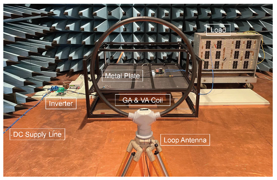
4.1. Test Bench Measurement Setup According to SAE J2954

Worldwide, there are several standardization organizations that deal with inductive charging. The four most important organizations for the standardization of WPT systems for electric vehicles are:
  • Society of Automotive Engineers (SAE);
  • International Electrotechnical Commission (IEC);
  • International Organization for Standardization (ISO);
  • Comité international spécial des perturbations radioélectriques (CISPR).
All these organizations have published a number of international standards, such as SAE J2954, IEC 61980-1/-2/-3 [47,48,49], CISPR 11 [50] and ISO 19363 [51]. They cover several topics and partly deal with different aspects of WPT systems. This includes topics such as general requirements and definitions, the physical design of the charging system, interoperability, transmission power and efficiency, radiation emission test methods, limit requirements and communication protocols for EV wireless charging systems. The recommended test setups for radiated emissions are harmonized between the SAE J2954 standard and the IEC 61980-3. The differences between the two standards are that SAE J2954 provides more standardized controls related to harmonics, fluctuations and flicker, as well as different configurations for conducted immunity testing [52]. An overview of the proposed test setups of the different standards for measuring the radiated emissions can be found in [5].
In this work, the EMC is investigated using a WPT system that complies with the SAE J2954. As stated by the standard, a typical WPT system consists of a ground assembly (GA), i.e., a primary side, and a vehicle assembly (VA), i.e., secondary side. In this case, the GA as well as the VA consist of the compensation circuit, the coil and the housing. In addition, the rectifier is also located in the VA. Furthermore, the frequency range of 79   kHz to 90   kHz shall be used for wireless power transmission according to SAE, where the operational nominal frequency is fixed as 85   kHz . Four different power level classes (WPT1-WPT4) and three different ground clearance classes (Z1, Z2 and Z3) are defined. The investigated WPT System belongs to WPT1 ( 3.7   kVA ) and class Z1 (100–150 mm). The recommended field limits are based on classifying the WPT function as FCC Part 18 under 30   MHz with modifications for the fundamental frequency. In comparison, the IEC 61980-1 refers to the CISPR 11 standard for the conducted and radiated emissions. The test bench measurement setup and limits are presently under development with CISPR 11, CISPR 25, and ANSI C63.30. The current setup proposal is depicted in Figure 8.
The test setup is located in a semi-anechoic chamber. From the center of the GA pad, an imaginary 1.9   m DUT ring is drawn. The antenna is then placed at a distance of 3   m or 10   m from this ring. In this case, deviating from the standard, the power electronic (PE) is fed only by a DC voltage source instead of the AC grid with an artificial mains network (AN). In addition, the test setup is not on a turntable, as required by the standard. The DC source can provide a max. input power of 15   k W . For EMC investigations the DC source is located outside the semi-anechoic chamber. The standard also normalizes the offset position with respect to the optimum position of the coils. The maximum offset is ± 75   m m in the fore and aft direction (x-axis) and ± 100   m m in the lateral direction (y-axis). The largest coupling factor k for the WPT system could be determined by measurements and results at min. z-offset ( 100   m m ), min. x-offset ( 0   m m ) and max. y-offset ( 100   m m ), which is due to the circular structure of GA and VA coil. This optimal offset positioning will be used for the further EMC investigations, as it represents the best case scenario. The purpose is to verify whether the current limit proposals are realistic for the power class considered in this work. Using the previously described frequency-tracking algorithm, a DC–DC efficiency of 91.9% at an operating frequency of 81.2   kHz can be achieved. Due to the fact that in practice an inductive phase angle of ϕ > 0 enables ZVS, which reduces switching losses in the MOSFETs, the optimal operating frequency is a little bit higher than the simulated resonance frequency. Moreover, the compensation elements and the coils have parasitic losses. At this operating point, the DC source must provide 252   V and 14.3   A to achieve an input power of 3.6   k W . At MPs 1-4, the currents are measured using a high-frequency current transformer (HFCT) in order to be able to subsequently measure and analyze the interference currents at various points in the WPT system. This allows conclusions to be drawn about where the largest interference currents occur.

4.2. EMC Investigation of WPT Systems

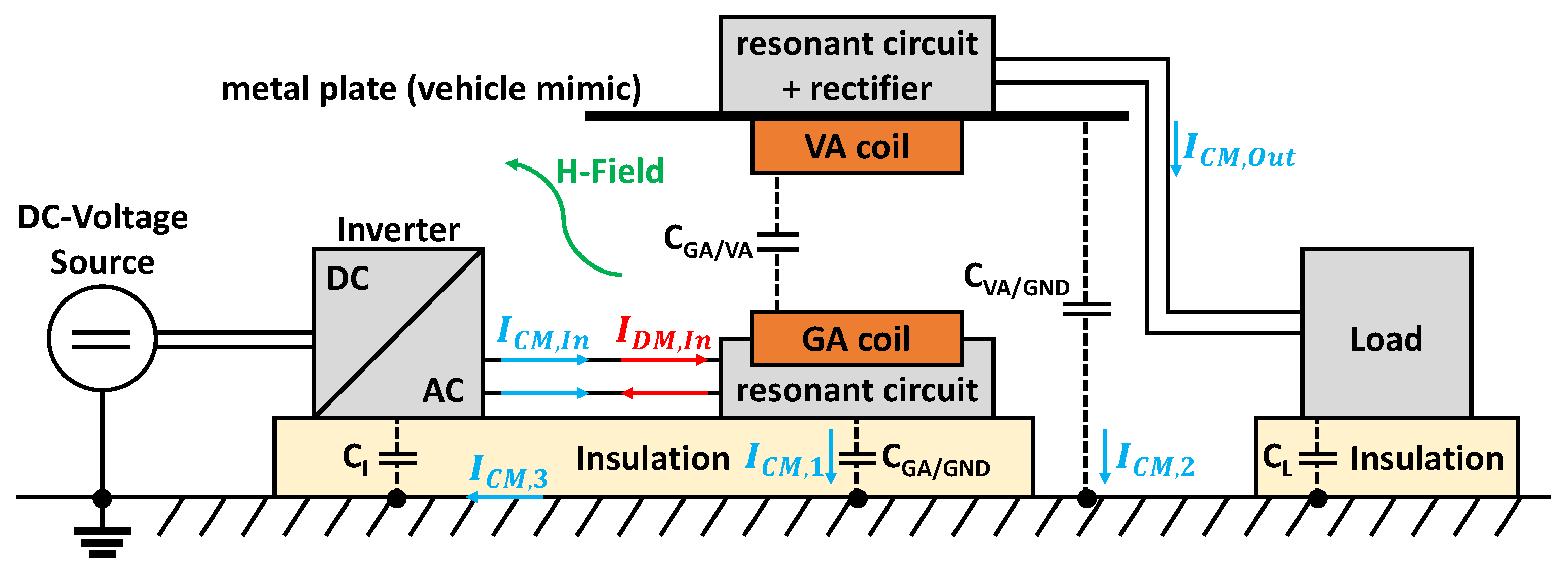
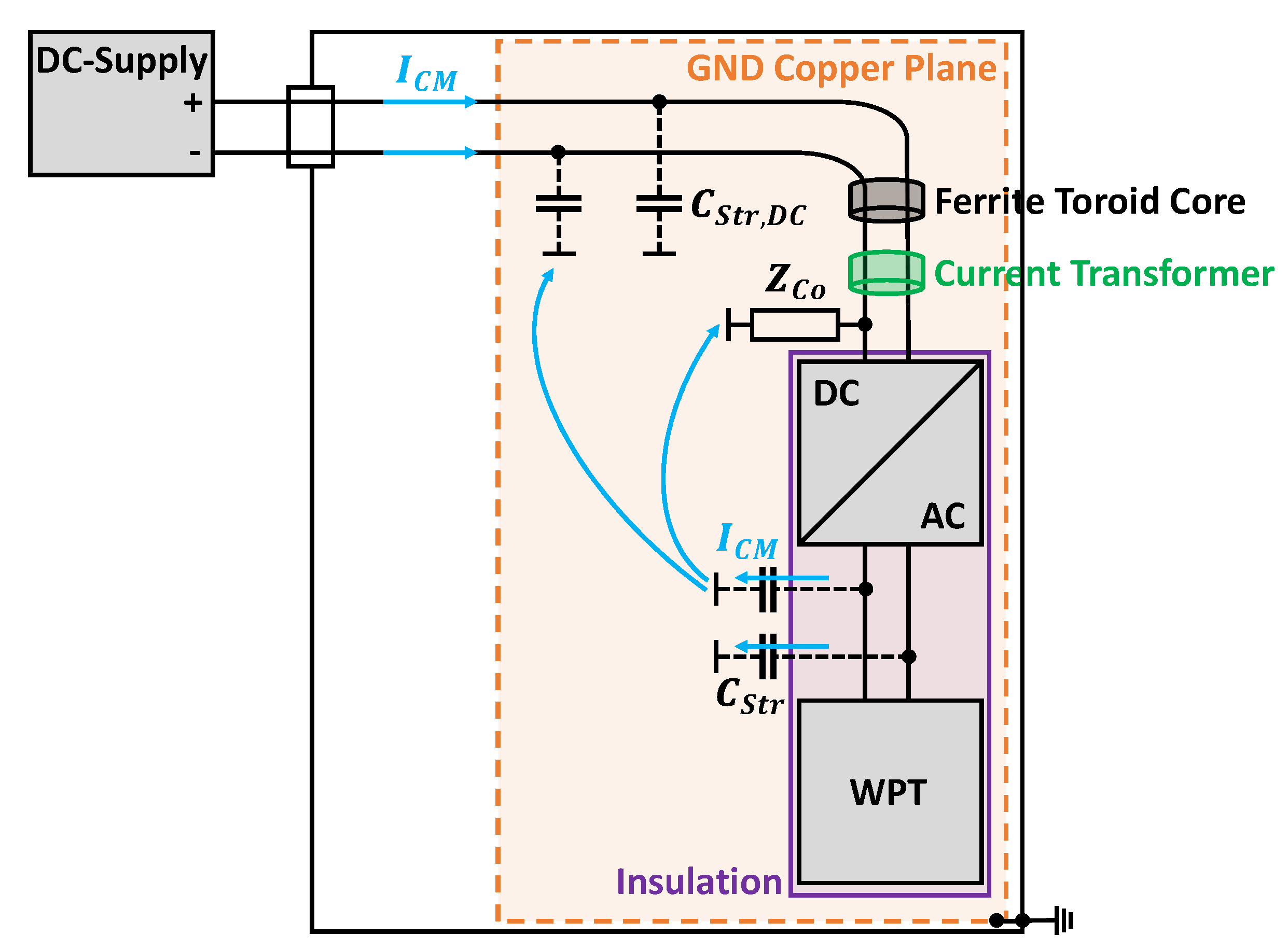
4.2.1. Essential Current Paths in WPT Systems

Starting from the inverter as power source, the primary coil is excited via the differential mode (DM) current I D M , I n , which also provides the transmitted energy. An ideal WPT system would have a common mode (CM) current amplitude of 0   A . However, in a real WPT system, different CM paths are present. CM currents can produce high field-strength values when magnetic field measurements are made. Figure 9 shows, in accordance with [9,10], the block diagram of a WPT system in an absorber-lined shielded enclosure (ALSE) and the resulting interference paths due to the parasitic capacitances.
For the EMC test in an ALSE, the WPT system is mounted on an insulating pad which is 5   c m high and placed on a conductive copper ground plane. Due to the resulting capacitive coupling between the components and the floor plate, there exist additional interference paths for CM. The CM current I C M , I n excited by the inverter flows via the supply line to the primary coil and splits here because of the resulting parasitic capacitances. One part of the current flows back to the reference ground via C G A / G N D and the remaining part couples via C G A / V A to the vehicle coil. For the resulting CM current I C M , 3 a path with high electrical conductivity results due to the metal plate. The following relationship is valid:
I C M , 3 = I C M , I n = I C M , 1 + I C M , 2 + I C M , O u t
By applying the model of a plate capacitor, the values of the parasitic capacitances can be approximated in a simplified way as follows:
C = ϵ 0 ϵ r A d
A corresponds to the area of the component parallel to the ground and d to the respective distance. Since styrodur is often used as insulation in EMC tests, this results in a relative permittivity of ϵ r 1 . As an example, this gives a value of C V A / G N D = 52   p F for the parasitic capacitance between the metal plate as vehicle mimic and the copper floor. Therefore the geometrical parameters of the test setup also have a major influence on the interference paths of the CM current.

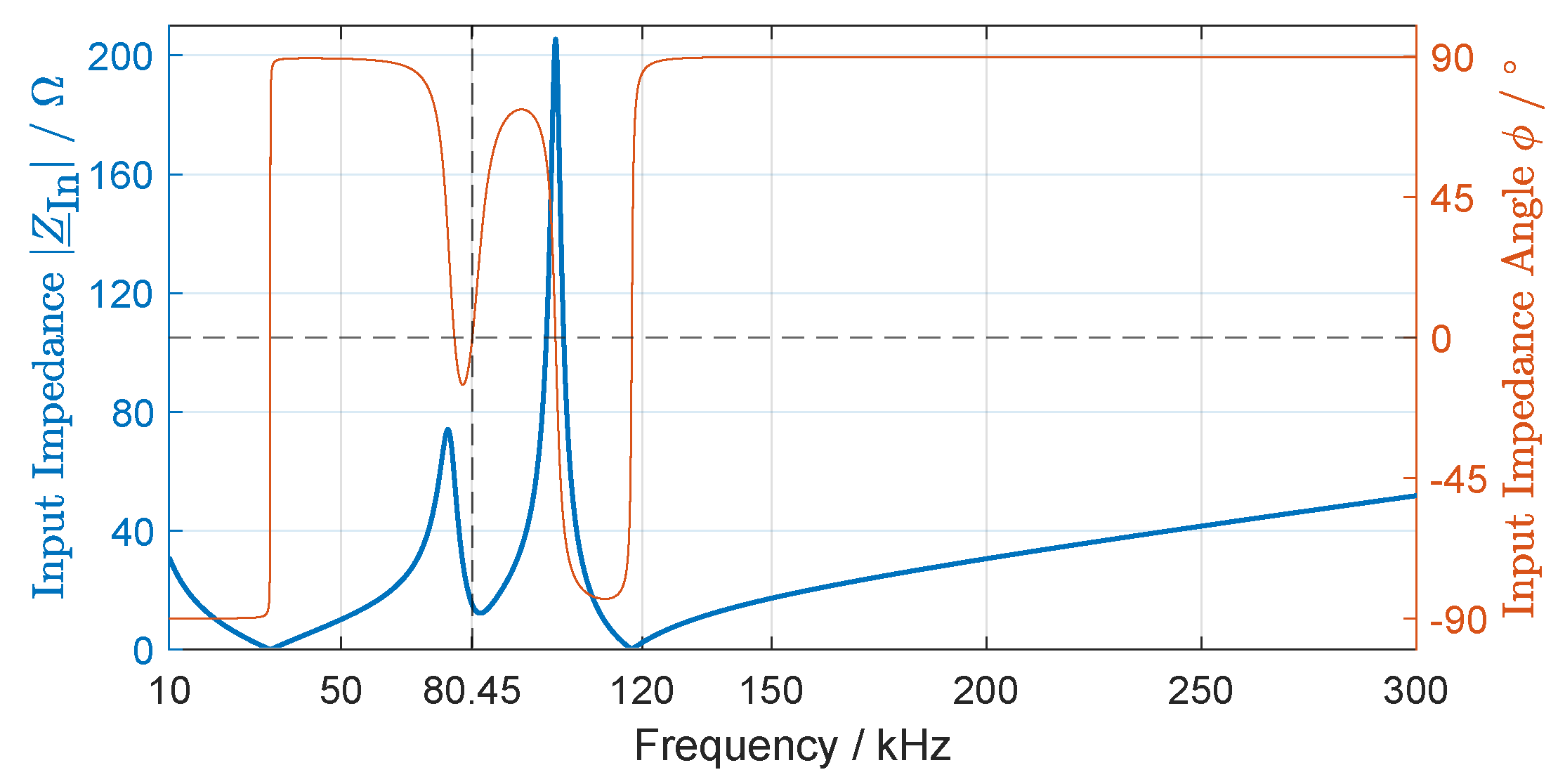
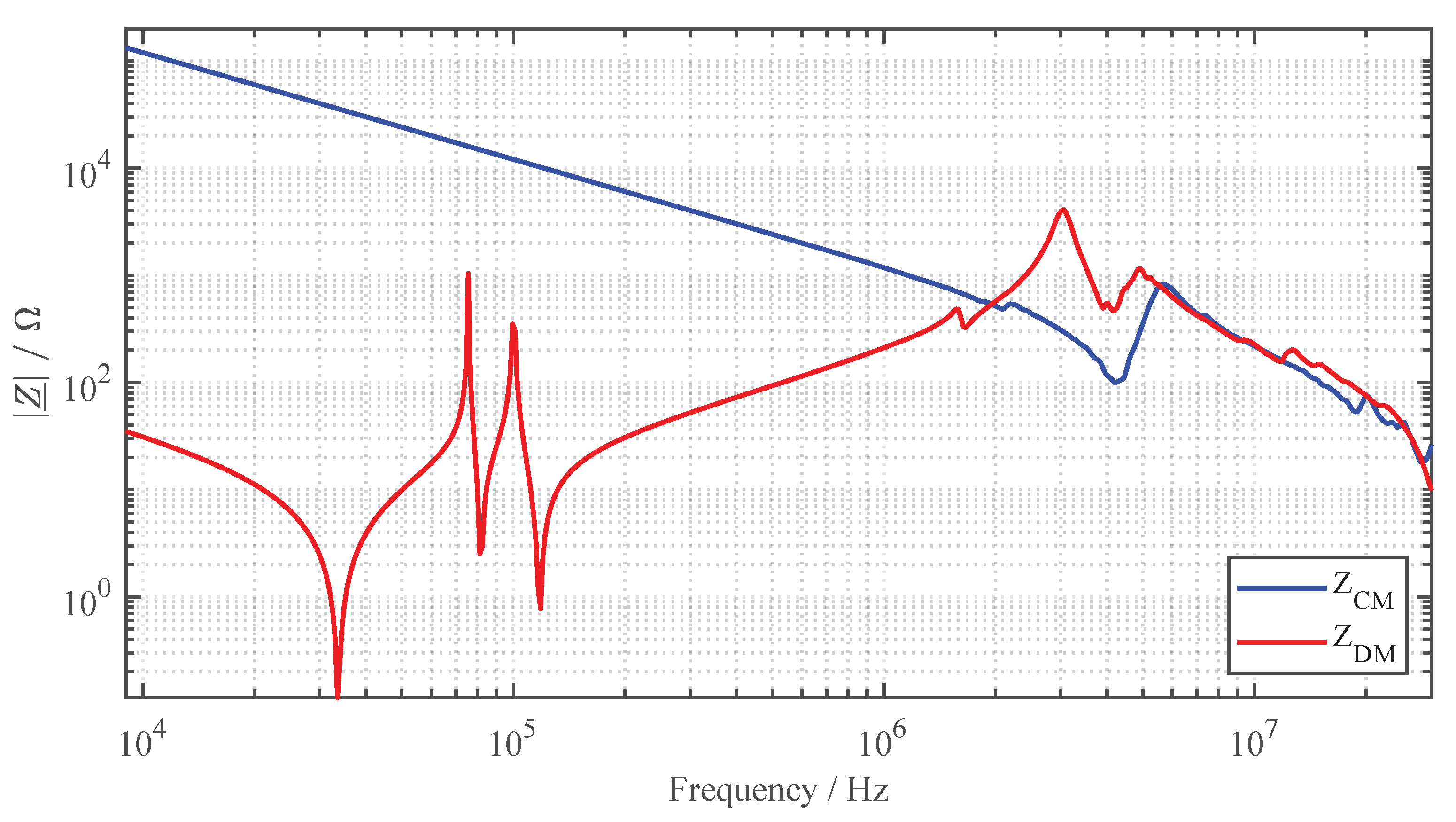
4.2.2. Impedance Behavior

In order to be able to analyze the interference currents occurring within the WPT system in the following sections, the impedance behavior and thus the previously described interference paths of the system are investigated. Similar studies were also presented in [13,53,54], where comparable results were obtained. For this purpose, an impedance analyzer type 4294A from Agilent is used.
The DM impedance is measured between the supply lines after the inverter into the primary coil. For CM impedance measurement, the supply lines to the primary coil are short-circuited and the impedance to the reference ground plane is measured. For this purpose, the outer conductor of the impedance analyzer is connected to the copper floor using copper tape with conductive adhesive. Figure 10 shows the results of the impedance measurements in a frequency range from 9   kHz to 30   MHz .
In the specified operating spectrum between 79   kHz and 90   kHz , the minimal DM impedance occurs at 81.2   kHz to | Z ̲ D M |   =   2.5   Ω . This also corresponds to the frequency at which the maximum efficiency of the system is achieved. Since the LCC-SP topology is a higher-order system, there is a total of five resonance frequencies up to approximately 118   kHz . The sixth resonance point at 3   MHz is caused by the parasitic capacitance between the windings of the primary coil. At the resonance point at 4.1   MHz , series resonance occurs due to the supply line inductance.
For the CM impedance, as expected, a capacitive behavior can be observed up to the resonant frequency of approximately 4.3   MHz . Using the CM impedance curve and following equation
C = 1 2 π f | Z ̲ C M |
the total parasitic coupling capacitance of the primary coil against the reference ground plane can be calculated, resulting in C = 133   p F . At the first resonance point, a series resonance with the supply line inductance occurs, as in the case of DM impedance. However, since there are differences in the supply line inductance when measuring the CM and DM impedance, there are deviations between the resonance points [54]. Especially with regard to public inductive charging systems, which can be designed with long supply lines, attention should be paid to a sufficient investigation of the interference currents due to the increased emissions at the resonance point. An extension of the supply line leads to a shift of the resonance to lower frequencies.

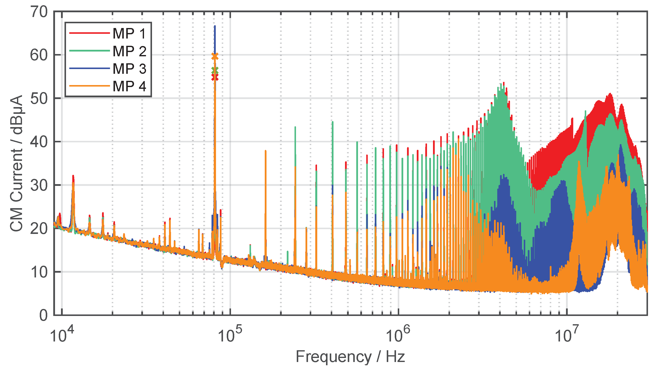
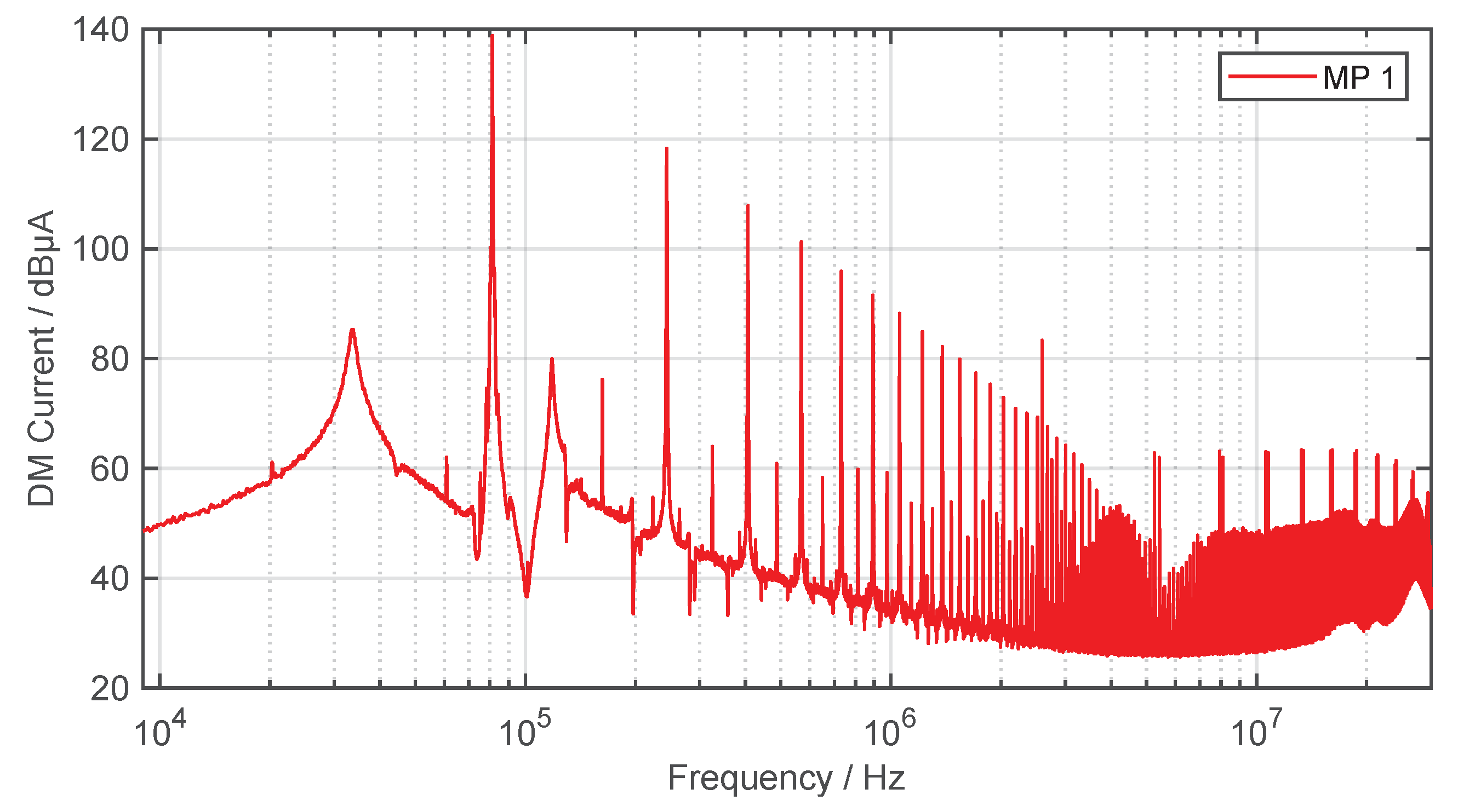
4.2.3. Conducted Interference Emissions

The CM and DM disturbances are mainly generated by the switching devices, such as MOSFETs or diodes. This is because they produce large voltage d v / d t and current d i / d t change rates, which will cause high-frequency signals [55]. Accordingly, this results in conducted and radiated electromagnetic emissions, which are especially strong directly at the output of the inverter. The CM current propagate capacitively to ground plate but also in the direction of the secondary coil. The measurement and limit of the CM current on the supply line between inverter and primary coil (MP 1) is also included in the draft of ETSI EN 303417, if the supply line exceeds a length of 3   m [56]. However, the limits for the CM interference current are still under discussion in the CISPR working group. Figure 11 shows the different CM currents at measurement points 1–4 in a frequency range from 9   kHz to 30   MHz . Similar investigations have been carried out in [14], but only for one measurement point (MP 1). The CM currents are measured using a current transformer with an internal ratio of 1:1 (Pearson Electronics, type 2100) and an EMI receiver (Gauss Instruments, type TDEMI X).
As expected, the harmonics of the operating frequency are most pronounced on the supply line from the inverter to the GA compensation. The spectrum shows both the even and odd harmonics. For MP 1 and 2, the even harmonics increase with 20 dB/dec up to about 4.3   MHz , at which point, as seen in Figure 10, the resonance point of the CM impedance occurs. At MP 3 and 4, the interference spectrum is strongly damped, i.e., filtering is performed by the two resonant circuits of the coils.
The DM current, as well as the effective current, is transmitted via the inductive coupling between primary and secondary coil. Figure 12 shows the DM current at MP 1 in a frequency range from 9   kHz to 30   MHz . The DM current is measured and evaluated using the same current transformer and EMI receiver as for CM measurements.
Due to the rectangular AC voltage of the inverter, mainly odd harmonics are seen in the spectrum [42]. As expected, the DM current shows high levels over the entire frequency spectrum. The decrease of 40 dB/dec for frequencies below 5   MHz is due to the inductive input impedance of the LC filter of the GA compensation with 20 dB/dec on the one hand and the decrease of a square wave pulse with 20 dB/dec in the spectrum on the other hand.

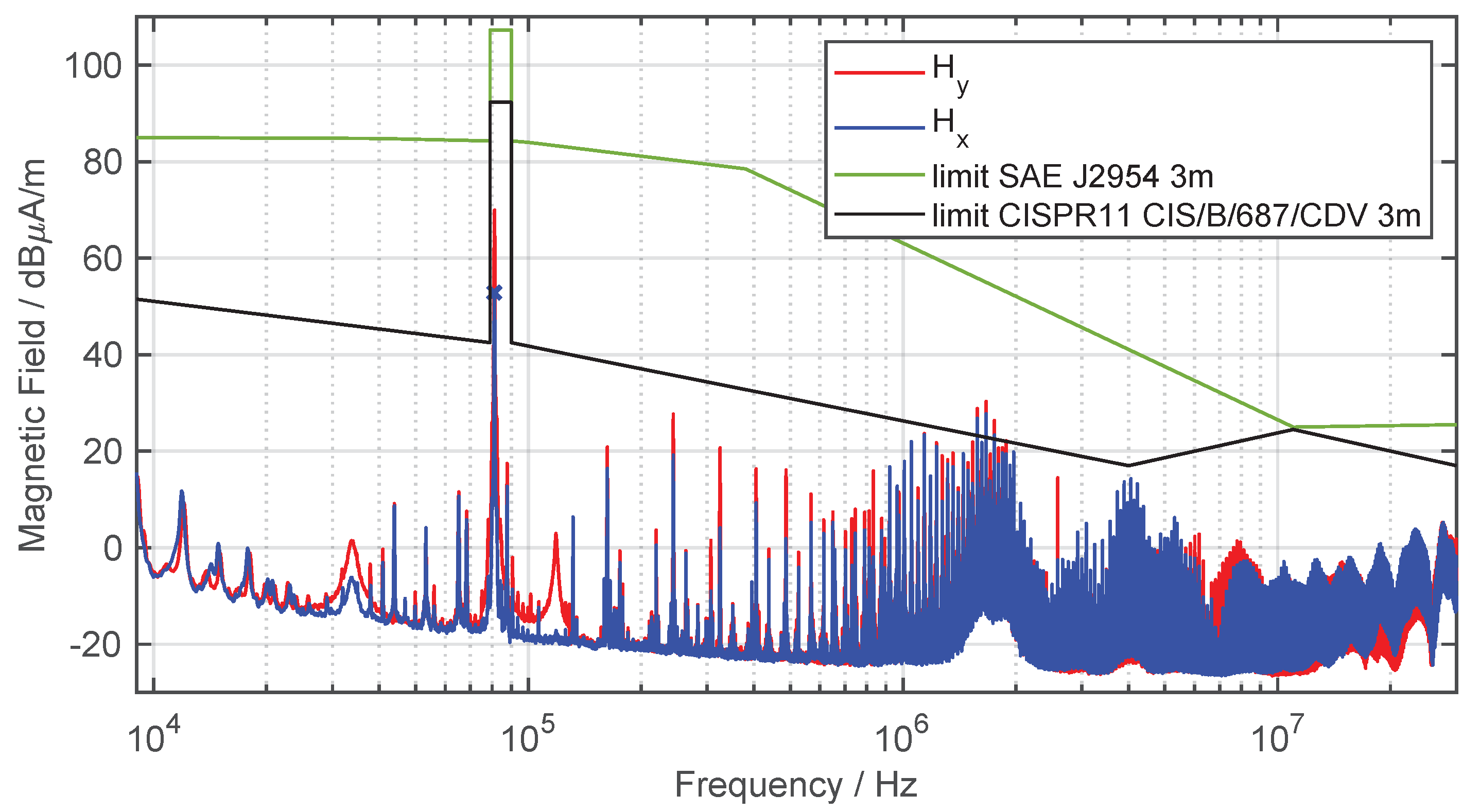
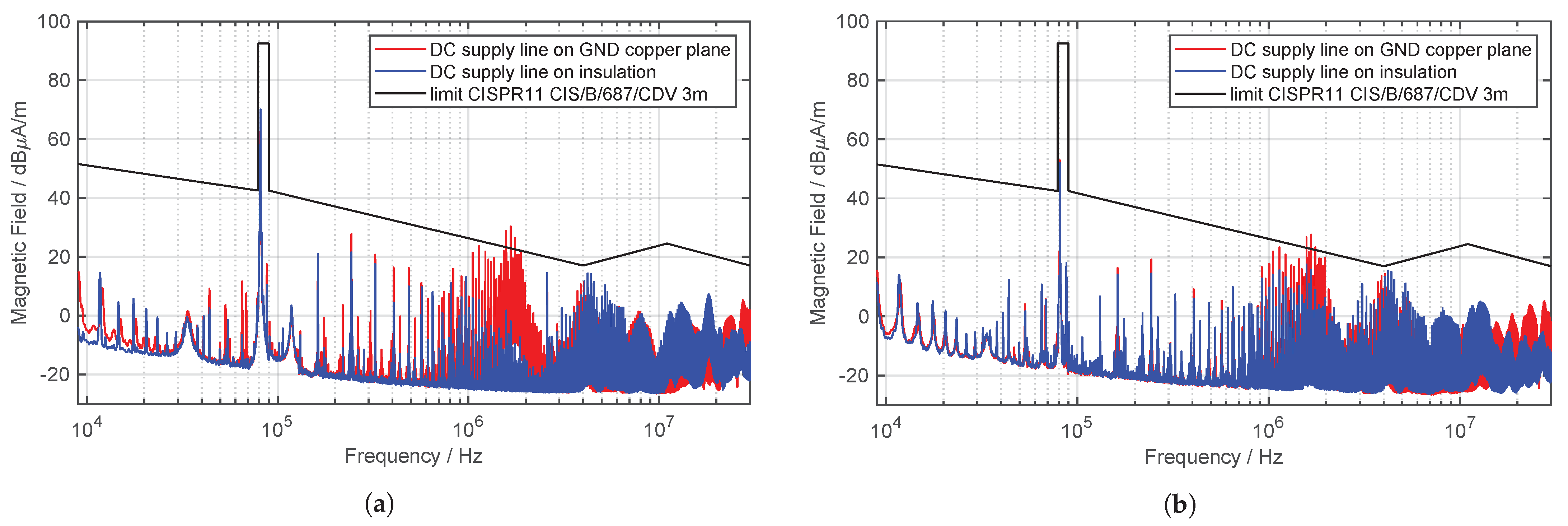
4.2.4. Field-Bound Interference Emissions

In order to protect the surrounding systems on both the infrastructure side and the vehicle side, it is necessary to evaluate the field-bound interference emissions. The evaluation of the H field of the overall system is performed by an active loop antenna (Rohde und Schwarz, type HFH 2-Z2). The radiated magnetic field of a WPT system is generated by a combination of DM and CM current and can be measured in the x and y direction. For this purpose, the antenna can be aligned at an angle of 0 to the test setup in order to measure the H y field. If the H x field needs to be measured, the antenna is aligned at an angle of 90 to the test setup. In Figure 13, the test setup is depicted, which is used to measure the H y field at a distance of 3   m from the WPT system.
Figure 14 shows the H field in both directions and the limit values of SAE J2954 and CISPR 11, for the WPT system in a frequency range from 9   kHz to 30   MHz . Due to the changed measurement distance from 10   m to 3   m , the EMC limits are adjusted.
The higher field value in the operating frequency range between 79   kHz and 90   kHz is allowed because it is chosen on purpose for this application. Outside the operating spectrum, stricter limits apply to avoid interference with radio services in neighboring frequency bands due to high-frequency harmonics. Above a frequency of about 400   kHz , the limits according to SAE are significantly tightened. According to CISPR 11, the level of max. radiated emission varies and depends on the power class of the WPT system. It is obvious that the limits of CISPR 11 are significantly stricter than those of the SAE.
As expected, the highest magnetic field strength is obtained at the operating frequency of the WPT system. The H x field reaches a value of 52.9  dB μ A / m , whereas H y has an increased amplitude of 20 dB. This is due to the field line characteristic of the circular coil. The H field measurements show similarities to the characteristics of the interference currents from Figure 11 and Figure 12. Up to a frequency of about 1   MHz , the DM current is mainly responsible for the interference emissions. With the decreasing level of the DM current, the harmonics in the interference spectrum also decrease. Above a frequency of 1   MHz , the influence of the CM current on the feed line dominates, since the characteristics of the harmonics are very similar and increase in both cases.
The limits of SAE standard are not exceeded at any frequency. The CISPR 11 limits are exceeded in the frequency range between 1   MHz to 2   MHz . Furthermore, the limits are only very narrowly complied with in the frequency range between 4   MHz to 4.3   MHz . With the current tendency to further tighten the limits, exceedances could also occur in this frequency range. Therefore, the following section investigates measures to decrease both conducted and field-bound interference emissions.

5. EMC Optimization of the Inductive Automotive Charging System

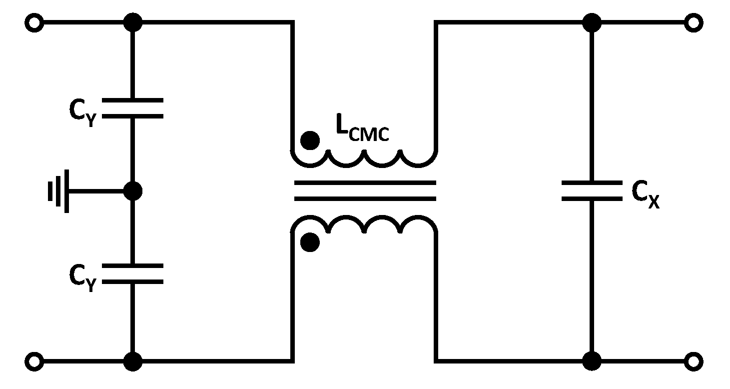
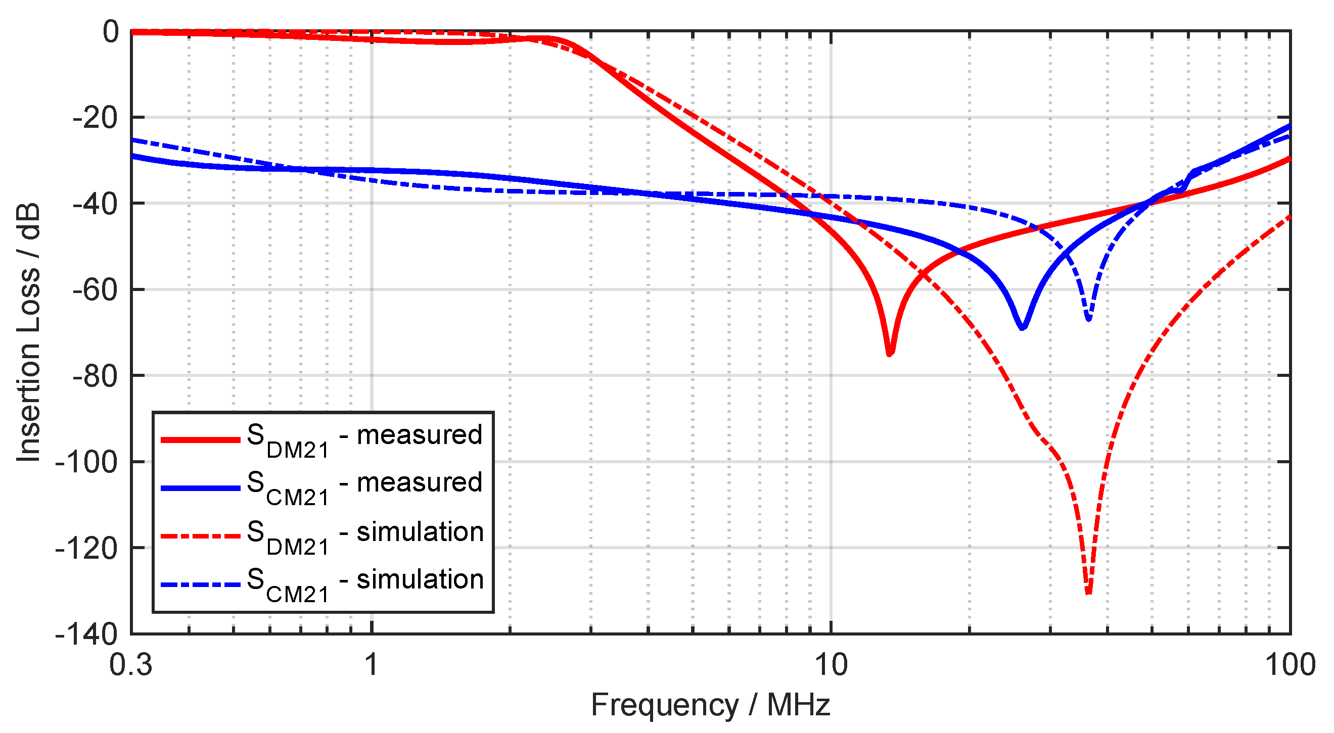
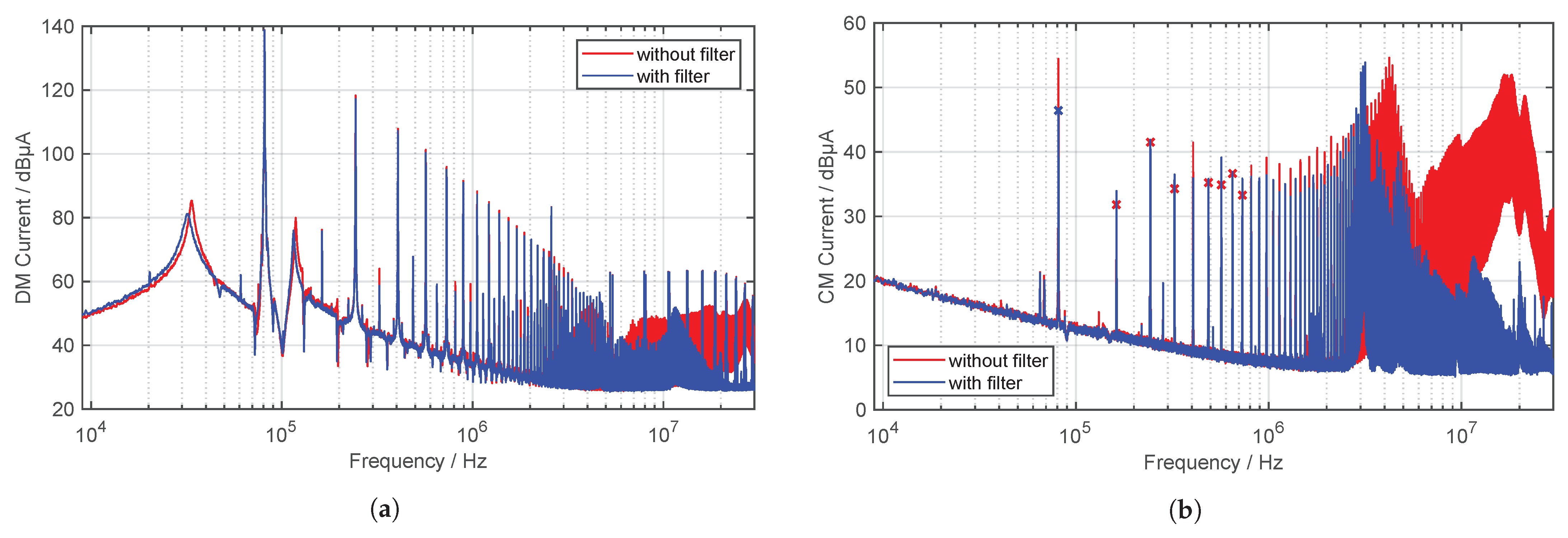
5.1. Filtering Measures

The H field generated by the DM current is ideally cancelled by good cable routing. This is because the DM current is a 180 phase-rotated current with identical amplitude in the forward and return conductors. When the pair of conductors is twisted, these opposite currents generate oppositely magnetic fields, which cancel each other. This is the reason why the filter design is primarily based on damping the CM currents. In addition, possible limits for the CM current are under discussion. Since the harmonics are especially prominent directly at the output of the inverter, a filter is constructed for this purpose according to Figure 15, between inverter and ground coil.
The challenge with this setup is that attention must be paid to the size of the capacitors. If the values are in the 100   n F range, the impedance at the operating frequency of 81.2   kHz is only 19.6   Ω . This means that the effective current will no longer flow into the primary coil, but will be conducted via the capacitors to GND until they are thermally destroyed. For this reason, a suitable common mode choke (CMC) must be selected. In a first step, a CMC is selected that achieves the highest possible attenuation at the first resonance point for the CM current and in the frequency range between 1   MHz to 2   MHz , since the CISPR limits for the H field are exceeded in this range. In this work, a CMC is used with an inductance of L C M C = 0.7   m H . In addition to the appropriate damping, the CMC has a sufficiently high DM current carrying capacity and voltage isolation. According to [57,58], the CM cutoff frequency of the filter shown in Figure 15 can be calculated as follows:
f C M = 1 2 π L C M C C C M with C C M = 2 · C Y
To achieve 40 dB attenuation at approximately 1   MHz , the CM cutoff frequency must be set to 1/10 for an insertion loss of 40 dB/dec. Thus, the cutoff frequency is about 100   kHz . The required C Y capacitance can now be determined to C Y = 1.8   n F by (10). According to [57,58], the DM cutoff frequency of the filter can be calculated as follows:
f D M = 1 2 π L D M C D M with C D M = C X and L D M = L L e a k a g e
The leakage inductance of a CMC can be estimated as 1% of the nominal inductance [57], resulting in L L e a k a g e = 7   μ H . Since the C X capacitor is not allowed to become too large and the C Y capacitors also contribute to DM damping, C X = 2   n F is selected. This results in a cutoff frequency of approximately f D M = 1.3   MHz .
To determine the insertion loss, the equivalent circuit of the filter is simulated using a SPICE simulation according to CISPR 17 standard. To validate the simulation results, a vector network analyzer (VNA) is used to perform a 4-port S-parameter measurement on the constructed filter in the 50   Ω system. The comparison in a frequency range from 300   kHz to 100   MHz is shown in Figure 16. Film capacitors are used for the filter.
The two simulated insertion losses are valid up to approximately 10   MHz with a max. deviation of 5 dB each. Especially for the CM attenuation ( S C M 21 ) high values are achieved. The resonance frequency is 10   MHz higher than in the measurement. At operating frequency the DM attenuation ( S D M 21 ) is almost 0 dB, which means that the efficiency of the WPT is not reduced. The resonance frequency is not met, but fits roughly. The deviation results from the conductor inductance of the PCB, parasitic properties of the components and from the inaccurate SPICE model of the CMC.
Since the filter effectiveness depends on the source and load resistance, various impedance ratios are provided for investigation in the CISPR 17 standard. These include 50   Ω / 50   Ω , 100   Ω / 0.1   Ω and 0.1   Ω / 100   Ω . The last two combinations represent worst-case scenarios and thus allow the evaluation of a filter in case of mismatch. Since the load impedance in a WPT system is highly dependent on the coupling factor and the state of charge of the battery, every change in the coil alignment and every charging process leads to a different filter characteristic. On the input side, only the DC source, the DC supply lines and the inverter are connected, which results in a low source impedance.
The next step is to install the constructed filter between the inverter and the primary coil to investigate its effectiveness and influence on the operating behavior of the WPT system. The measured CM current on the supply line behind the filter (MP 1) can be seen in Figure 17.
For the DM current, as expected, there is not much attenuation of the current levels in the lower frequency range due to the filter design. In the higher frequency range, from around 4   MHz , a noticeable attenuation can be recognized. At the operating frequency of the WPT system, there is an attenuation of approximately 8 dB for the CM current. In the higher frequency range, current levels are reduced by more than 30 dB. However, it can be seen that through the use of the filter and the associated capacitors, the original resonance point at 4.3   MHz is shifted down by about 1   MHz . When CM current limits occur, a shift in the resonant frequency could have important consequences for complying with the limit values. In addition, parasitic oscillation and ringing of the inverter output voltage occur [59] when operating with a filter, which causes even more EMC problems. This is due to the parasitic inductances of the film capacitors. Resistors for damping should therefore be considered in future filter circuits.

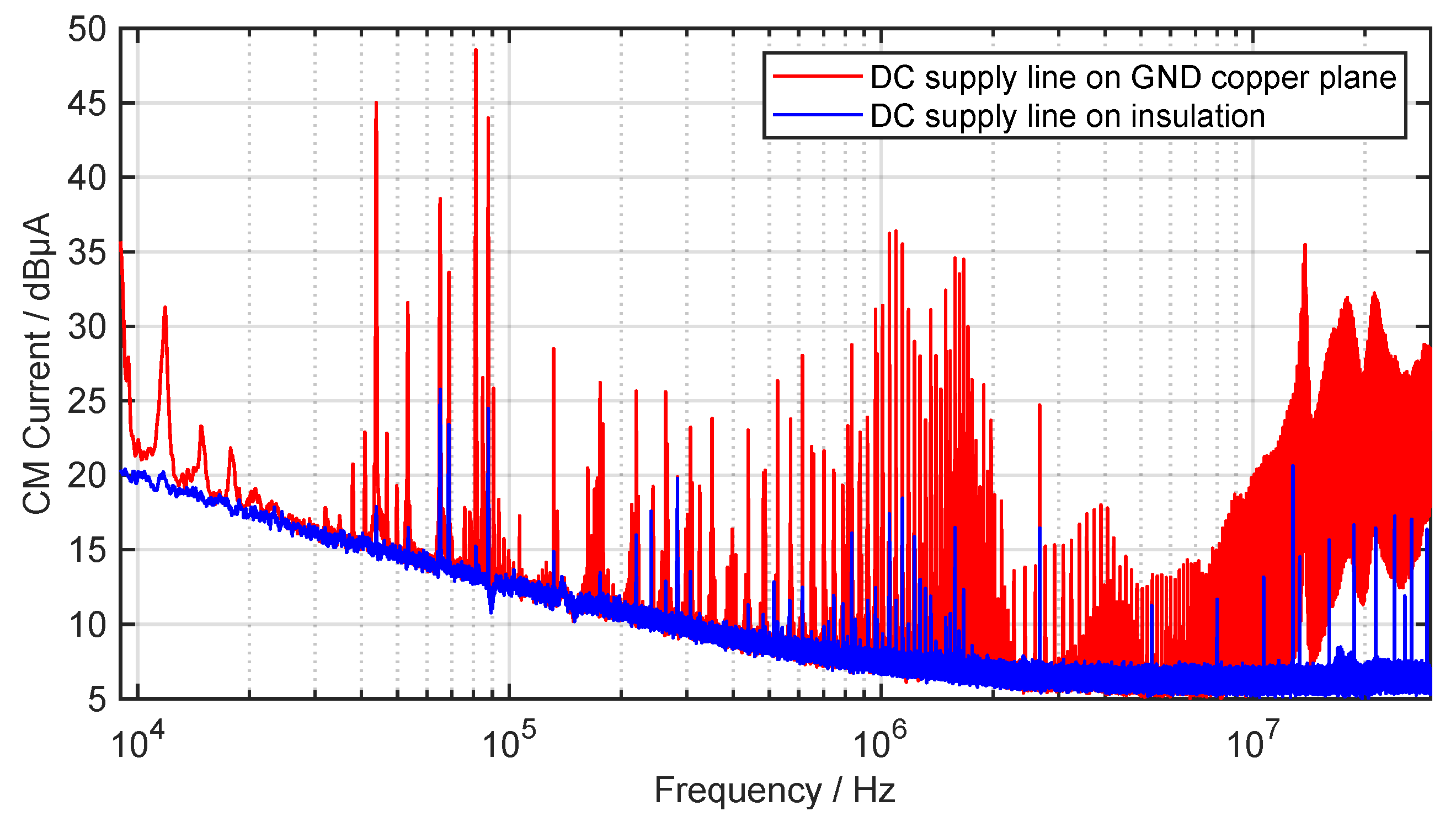
5.2. Influence of the DC Supply Line

Another focus of this work is to investigate the influence of the the DC supply line on the radiated H field. Since in practice long supply lines are conceivable in parking areas, this is an important factor for the EMC evaluation of WPT systems. In the current test bench setup, the DC supply line has a length of more than 10   m and lies directly on the GND copper plane, which is schematically depicted in Figure 18.
Since the DC source generates additional interference currents, a ferrite toroid core is used before the input of the inverter to attenuate the CM current. This will enable a better interference evaluation of the WPT system, since a clean voltage supply can be assumed on the grid side. The CM current is measured after the ferrite, close to the input of the inverter, which is grounded via a cable with impedance Z C o from the negative terminal. There are two possible current paths for the CM currents emanating from the inverter via the parasitic stray capacitances C S t r . The first one is directly over the cable and the second one is through the parasitic stray capacitances C S t r , D C . The parasitic capacitance between the DC supply line and GND is distributed over the entire cable and is large due to the direct contact. If the interference currents flow on the DC cable, they in turn radiate an H field, which is also measured with the loop antenna. So in order to avoid a large ground loop and to prevent the CM currents from coupling to the DC cable, | Z ̲ C S t r , D C | | Z ̲ C o | must be valid. Figure 19 shows the CM current on the DC supply line while the DC cable lies directly on the copper ground (red) and on an insulation which is 50   c m high (blue), in order to reduce the stray capacitance C S t r , D C of the DC cable.
It can be seen that the CM current is drastically reduced by increasing the distance to GND and the consequently reduced stray capacitance C S t r , D C . The measured H field of the entire test setup of the WPT system is depicted in Figure 20 in a frequency range from 9   kHz to 30   MHz , with the same configuration as for the measurement of the CM current.
As expected, due to the decreased CM current on the DC supply line, the emitted H field is reduced. Especially in the frequency range between 1   MHz and 2   MHz , a significant improvement can be seen. The CM current also shows a significantly reduced current level in this frequency range. At the operating frequency of the WPT system, the H field level results from the DM current through the coils and not from the CM current on the DC supply line. Therefore, no influence can be seen at this frequency. The limits of CISPR 11 are now complied over the entire frequency spectrum. This simple test illustrates the importance of considering the influence of the DC supply line and the parasitic stray capacitance C S t r , D C on the radiated magnetic field. During EMC investigations in a semi-anechoic chamber it is very important to have exact specifications about the supply line of the WPT system, in order to enable the reproducibility of measurement results. Therefore, the standard should precisely define, among other things, the length of the supply line, how the cable should be laid and/or also the corresponding distance to GND. These are factors which have a very great impact on the result of the EMC tests.

6. Conclusions

In this article, the fundamentals of inductive charging for electric vehicles are presented and related to EMC. The basic compensation topologies are compared and, in addition, the advantage of high-order compensation topologies is discussed. The full-bridge inverter and its influence on the efficiency and EMC of WPT systems is presented. The investigations that are carried out in this article were performed on a 3.6   k W WPT system, which is standardized according to SAE J2954. Furthermore, other standardization organizations are presented and their topics regarding inductive charging as well as possible limit value proposals are compared with each other. With a new presented frequency-tracking algorithm, the optimal operating frequency of a WPT system can be found to achieve the highest efficiency. The impedance profile shows that high interference currents can occur especially at the resonance points between the parasitic capacitance and the primary coil, as well as to the supply line inductance. The CM and DM currents investigated at the different measuring points indicate that a filter should be considered, especially at the output of the inverter, particularly in consideration of the fact that current limit proposals for the CM current are under discussion. The designed filter achieves good results for the attenuation of the CM current. However, care must be taken to ensure sufficient damping, since the capacitors increase the ringing phenomenon at the output voltage of the inverter. The results of the magnetic field measurements show that the limits of CISPR 11, in contrast to those of the SAE, have not been met, although with the max. magnetic coupling between the coils the best-case scenario is investigated. The test bench setup used in this work contains H field components from the DC supply line to the inverter in addition to the field components from the coil setup. By investigating the influence of the DC supply line to the inverter, it is subsequently possible to comply with the limit specifications by geometric adjustment. This underlines the significance of the standardized test bench setup. In future work, the E field of the WPT system should also be considered to provide new knowledge for evaluating the interference potential. Furthermore, the development of advanced filtering techniques can help to better attenuate the CM and DM currents even in the lower-frequency range. Since in realistic scenarios a misalignment of the GA coil to the VA coil may occur, this impact should also be investigated on the EMC behavior. In addition, recommendations for the supply line of the inverter should be made in the standard. Within the scope of this work, the shortest possible cable with a greater distance to the ground has proven to be advantageous.

Author Contributions

Conceptualization, E.S., M.B. and S.T.; Methodology, E.S.; Software, E.S.; Validation, E.S. and M.B.; Formal analysis, E.S. and M.B.; Investigation, E.S.; Resources, S.T.; Data curation, E.S.; Writing—original draft preparation, E.S.; Writing—review and editing, M.B. and S.T.; Visualization, E.S.; Supervision, S.T.; Project administration, E.S., M.B. and S.T. All authors have read and agreed to the published version of the manuscript.

Funding

This research received no external funding.

Institutional Review Board Statement

Not applicable.

Informed Consent Statement

Not applicable.

Data Availability Statement

Not applicable.

Conflicts of Interest

The authors declare no conflict of interest.

References

  1. Noeren, J.; Parspour, N.; Elbracht, L. An easily scalable dynamic wireless power transfer system for electric vehicles. Energies 2023, 16, 3936. [Google Scholar] [CrossRef]
  2. Xue, L.; Galigekere, V.; Su, G.j.; Zeng, R.; Mohammad, M.; Gurpinar, E.; Chowdhury, S.; Onar, O. Design and Analysis of a 200 kW Dynamic Wireless Charging System for Electric Vehicles. In Proceedings of the 2022 IEEE Applied Power Electronics Conference and Exposition (APEC), Houston, TX, USA, 20–24 March 2022; pp. 1096–1103. [Google Scholar]
  3. Jiang, L.; Liu, H.; Zhang, X. Analysis on EMC influencing factors of electric vehicle wireless charging system. In Proceedings of the 2021 IEEE International Joint EMC/SI/PI and EMC Europe Symposium, Raleigh, NC, USA, 26 July–13 August 2021; pp. 285–290. [Google Scholar]
  4. Grazian, F.; Shi, W.; Dong, J.; van Duijsen, P.; Soeiro, T.B.; Bauer, P. Survey on Standards and Regulations for Wireless Charging of Electric Vehicles. In Proceedings of the 2019 AEIT International Conference of Electrical and Electronic Technologies for Automotive (AEIT AUTOMOTIVE), Turin, Italy, 2–4 July 2019; pp. 1–5. [Google Scholar]
  5. Jiang, L.; Liu, H.; Wang, C. Summary of EMC Test Standards for Wireless Power Transfer Systems of Electric Vehicles. In Proceedings of the 2021 Asia-Pacific International Symposium on Electromagnetic Compatibility (APEMC), Bali, Indonesia, 27–30 September 2021; pp. 1–4. [Google Scholar]
  6. Obayashi, S.; Tsukahara, H. EMC issues on wireless power transfer. In Proceedings of the 2014 International Symposium on Electromagnetic Compatibility, Tokyo, Japan, 12–16 May 2014; pp. 601–604. [Google Scholar]
  7. Ziegler, C.; Beck, F. Entwicklung eines Messaufbaus zur Charakterisierung der WPT-Systemkomponenten nach CISPR 25 und CISPR 11. In Proceedings of the EMV: Internationale Fachmesse und Kongress für Elektromagnetische Verträglichkeit, Dusseldorf, Germany, 23–25 February 2016; pp. 377–384. [Google Scholar]
  8. Willmann, B.; Cuartielles Ruiz, D.; Vick, R. Wireless Power Transfer-Stand der Normungsaktivitäten. In Proceedings of the EMV: Internationale Fachmesse und Kongress für Elektromagnetische Verträglichkeit, Dusseldorf, Germany, 20–22 February 2018; pp. 359–367. [Google Scholar]
  9. Ziegler, C.; Weber, S.; Heiland, G. Propagation Paths and Filter Methods for Common Mode (CM) Currents in WPT systems for Electrical Vehicles (EV). In Proceedings of the PCIM Europe 2019; International Exhibition and Conference for Power Electronics, Intelligent Motion, Renewable Energy and Energy Management, Nuremberg, Germany, 7–9 May 2019; pp. 1–7. [Google Scholar]
  10. Ziegler, C.; Weber, S.; Heiland, G. Ursache von Gleichtaktstörströmen in induktiven Ladesystemen (WPT-Systeme) und Vergleich zwischen gemessenen Störströmen mit der Feldstärkemessung. In Proceedings of the EMV: Internationale Fachmesse und Kongress für Elektromagnetische Verträglichkeit, Cologne, Germany, 17–19 March 2020; pp. 37–45. [Google Scholar]
  11. Zhai, L.; Cao, Y.; Lin, L.; Zhang, T.; Kavuma, S. Mitigation conducted emission strategy based on transfer function from a DC-Fed wireless charging system for electric vehicles. Energies 2018, 11, 477. [Google Scholar] [CrossRef]
  12. Simonazzi, M.; Sandrolini, L. Conducted Emission Analysis of a Near-Field Wireless Power Transfer System. In Proceedings of the 2021 IEEE 15th International Conference on Compatibility, Power Electronics and Power Engineering (CPE-POWERENG), Florence, Italy, 14–16 July 2021; pp. 1–6. [Google Scholar]
  13. Jeschke, S.; Maarleveld, M.; Baerenfaenger, J.; Schmuelling, B.; Burkert, A. Challenges in EMC Testing of EV and EVSE Equipment for Inductive Charging. In Proceedings of the 2018 International Symposium on Electromagnetic Compatibility (EMC EUROPE), Amsterdam, The Netherlands, 27–30 August 2018; pp. 967–971. [Google Scholar]
  14. Haug, M.; Beltle, M.; Tenbohlen, S. Magnetic Field Emission of Automotive Inductive Charging Systems in the 9 kHz–30 MHz Range. In Proceedings of the 2021 Asia-Pacific International Symposium on Electromagnetic Compatibility (APEMC), Bali, Indonesia, 27–30 September 2021; pp. 1–4. [Google Scholar]
  15. Haug, M.; Beltle, M.; Tenbohlen, S. Modellierung von Wireless Power Transfer (WPT) Systemen zur Analyse der magnetischen Feldemissionen. In Proceedings of the EMV: Internationale Fachmesse und Kongress für Elektromagnetische Verträglichkeit, Cologne, Germany, 17–19 March 2020; pp. 47–54. [Google Scholar]
  16. Campi, T.; Cruciani, S.; Maradei, F.; Feliziani, M. Magnetic field during wireless charging in an electric vehicle according to standard SAE J2954. Energies 2019, 12, 1795. [Google Scholar] [CrossRef]
  17. Hu, J.; Xu, X.; Zheng, T.; Lan, H.; Cao, D.; Liu, G. Experimental Study of Radiated Magnetic Field from Electric Vehicle Wireless Charging System. IEEE Electromagn. Compat. Mag. 2021, 10, 46–51. [Google Scholar] [CrossRef]
  18. Kuerschner, D.; Ombach, G.; Percebon, L.; Mathar, S. Magnetic leakage field study of a 7 kW wireless electric vehicle charging system. World Electr. Veh. J. 2016, 8, 501–510. [Google Scholar] [CrossRef]
  19. Jeschke, S.; Maarleveld, M.; Baerenfaenger, J.; Hirsch, H.; Tsiapenko, S.; Waldera, C.; Obholz, M. Development of a passive impedance network for modeling electric vehicle traction batteries for EMI measurements. In Proceedings of the 2017 International Symposium on Electromagnetic Compatibility—EMC EUROPE, Angers, France, 4–7 September 2017; pp. 1–6. [Google Scholar]
  20. Haug, M.; Beltle, M.; Tenbohlen, S. Grundlegende Betrachtungen der Kopplungsmechanismen möglicher Störgrößen für induktive KFZ-Ladesysteme. In Proceedings of the EMV: Internationale Fachmesse und Kongress für Elektromagnetische Verträglichkeit, Dusseldorf, Germany, 20–22 February 2018; pp. 548–555. [Google Scholar]
  21. SAE J2954; Wireless Power Transfer for Light-Duty Plug-In/Electric Vehicles and Alignment Methodology. SAE International: Warrendale, PA, USA, 2022.
  22. CIS/B/687/CDV; Amendment 2 Fragment 1 to CISPR 11 Ed. 6: Industrial, Scientific and Medical Equipment—Radio-Frequency Disturbance Characteristics—Limits and Methods of Measurement —Requirements for Air-Gap Wireless Power Transfer (WPT). CISPR: Geneva, Switzerland, 2017.
  23. Okasili, I.; Elkhateb, A.; Littler, T. A review of wireless power transfer systems for electric vehicle battery charging with a focus on inductive coupling. Electronics 2022, 11, 1355. [Google Scholar] [CrossRef]
  24. Feng, H.; Tavakoli, R.; Onar, O.C.; Pantic, Z. Advances in High-Power Wireless Charging Systems: Overview and Design Considerations. IEEE Trans. Transp. Electrif. 2020, 6, 886–919. [Google Scholar] [CrossRef]
  25. Wang, C.S.; Stielau, O.; Covic, G. Design considerations for a contactless electric vehicle battery charger. IEEE Trans. Ind. Electron. 2005, 52, 1308–1314. [Google Scholar] [CrossRef]
  26. Bi, Z.; Kan, T.; Mi, C.C.; Zhang, Y.; Zhao, Z.; Keoleian, G.A. A review of wireless power transfer for electric vehicles: Prospects to enhance sustainable mobility. Appl. Energy 2016, 179, 413–425. [Google Scholar] [CrossRef]
  27. Zhang, W.; Mi, C.C. Compensation Topologies of High-Power Wireless Power Transfer Systems. IEEE Trans. Veh. Technol. 2016, 65, 4768–4778. [Google Scholar] [CrossRef]
  28. Sallan, J.; Villa, J.L.; Llombart, A.; Sanz, J.F. Optimal Design of ICPT Systems Applied to Electric Vehicle Battery Charge. IEEE Trans. Ind. Electron. 2009, 56, 2140–2149. [Google Scholar] [CrossRef]
  29. Aditya, K.; Williamson, S.S. Comparative study of Series-Series and Series-Parallel compensation topologies for electric vehicle charging. In Proceedings of the 2014 IEEE 23rd International Symposium on Industrial Electronics (ISIE), Istanbul, Turkey, 1–4 June 2014; pp. 426–430. [Google Scholar]
  30. Villa, J.L.; Sallan, J.; Sanz Osorio, J.F.; Llombart, A. High-Misalignment Tolerant Compensation Topology For ICPT Systems. IEEE Trans. Ind. Electron. 2012, 59, 945–951. [Google Scholar] [CrossRef]
  31. Wang, C.S.; Covic, G.; Stielau, O. Power transfer capability and bifurcation phenomena of loosely coupled inductive power transfer systems. IEEE Trans. Ind. Electron. 2004, 51, 148–157. [Google Scholar] [CrossRef]
  32. Vu, V.B.; Ramezani, A.; Triviño, A.; González-González, J.M.; Kadandani, N.B.; Dahidah, M.; Pickert, V.; Narimani, M.; Aguado, J. Operation of Inductive Charging Systems Under Misalignment Conditions: A Review for Electric Vehicles. IEEE Trans. Transp. Electrif. 2023, 9, 1857–1887. [Google Scholar] [CrossRef]
  33. Patil, D.; McDonough, M.K.; Miller, J.M.; Fahimi, B.; Balsara, P.T. Wireless Power Transfer for Vehicular Applications: Overview and Challenges. IEEE Trans. Transp. Electrif. 2018, 4, 3–37. [Google Scholar] [CrossRef]
  34. Wang, Y.; Yao, Y.; Liu, X.; Xu, D. S/CLC Compensation Topology Analysis and Circular Coil Design for Wireless Power Transfer. IEEE Trans. Transp. Electrif. 2017, 3, 496–507. [Google Scholar] [CrossRef]
  35. Song, K.; Li, Z.; Jiang, J.; Zhu, C. Constant Current/Voltage Charging Operation for Series–Series and Series–Parallel Compensated Wireless Power Transfer Systems Employing Primary-Side Controller. IEEE Trans. Power Electron. 2018, 33, 8065–8080. [Google Scholar] [CrossRef]
  36. Qu, X.; Han, H.; Wong, S.C.; Tse, C.K.; Chen, W. Hybrid IPT Topologies With Constant Current or Constant Voltage Output for Battery Charging Applications. IEEE Trans. Power Electron. 2015, 30, 6329–6337. [Google Scholar] [CrossRef]
  37. Triviño, A.; González-González, J.M.; Aguado, J.A. Wireless power transfer technologies applied to electric vehicles: A review. Energies 2021, 14, 1547. [Google Scholar] [CrossRef]
  38. Wang, Y.; Xiong, M.; Wang, X.; Li, Q.; Jiang, Z.; Wei, X.; Dai, H. Research on 11kW Wireless Charging System for Electric Vehicle Based on LCC-SP Topology and Current Doubler. In Proceedings of the 2020 IEEE Energy Conversion Congress and Exposition (ECCE), Detroit, MI, USA, 11–15 October 2020; pp. 820–827. [Google Scholar]
  39. Yang, J.; Zhang, X.; Zhang, K.; Cui, X.; Jiao, C.; Yang, X. An LCC-SP Compensated Inductive Power Transfer System and Design Considerations for Enhancing Misalignment Tolerance. IEEE Access 2020, 8, 193285–193296. [Google Scholar] [CrossRef]
  40. González-González, J.M.; Triviño-Cabrera, A.; Aguado, J.A. Assessment of the Power Losses in a SAE J2954-Compliant Wireless Charger. IEEE Access 2022, 10, 54474–54483. [Google Scholar] [CrossRef]
  41. Hazra, S.; De, A.; Cheng, L.; Palmour, J.; Schupbach, M.; Hull, B.A.; Allen, S.; Bhattacharya, S. High Switching Performance of 1700-V, 50-A SiC Power MOSFET Over Si IGBT/BiMOSFET for Advanced Power Conversion Applications. IEEE Trans. Power Electron. 2016, 31, 4742–4754. [Google Scholar]
  42. Namin, A.; Chaidee, E.; Sriprom, T.; Bencha, P. Performance of Inductive Wireless Power Transfer Between Using Pure Sine Wave and Square Wave Inverters. In Proceedings of the 2018 IEEE Transportation Electrification Conference and Expo, Asia-Pacific (ITEC Asia-Pacific), Bangkok, Thailand, 6–9 June 2018; pp. 1–5. [Google Scholar]
  43. Zou, S.; Onar, O.C.; Galigekere, V.; Pries, J.; Su, G.J.; Khaligh, A. Secondary Active Rectifier Control Scheme for a Wireless Power Transfer System with Double-Sided LCC Compensation Topology. In Proceedings of the IECON 2018—44th Annual Conference of the IEEE Industrial Electronics Society, Washington, DC, USA, 21–23 October 2018; pp. 2145–2150. [Google Scholar]
  44. Kim, H.; Jeong, S.; Kim, D.H.; Kim, J.; Kim, Y.I.; Kim, I.M. Selective harmonic elimination method of radiation noise from automotive wireless power transfer system using active rectifier. In Proceedings of the 2016 IEEE 25th Conference on Electrical Performance Of Electronic Packaging And Systems (EPEPS), San Diego, CA, USA, 23–26 October 2016; pp. 161–164. [Google Scholar]
  45. Wang, Y.; Yao, Y.; Liu, X.; Xu, D.; Cai, L. An LC/S Compensation Topology and Coil Design Technique for Wireless Power Transfer. IEEE Trans. Power Electron. 2018, 33, 2007–2025. [Google Scholar] [CrossRef]
  46. Steigerwald, R. A comparison of half-bridge resonant converter topologies. IEEE Trans. Power Electron. 1988, 3, 174–182. [Google Scholar] [CrossRef]
  47. IEC 61980-1; Electric Vehicle Wireless Power Transfer (WPT) Systems—Part 1: General Requirements. IEC: Geneva, Switzerland, 2020.
  48. IEC 61980-2; Electric Vehicle Wireless Power Transfer (WPT) Systems—Part 2: Specific Requirements for MF-WPT System Communication and Activities. IEC: Geneva, Switzerland, 2023.
  49. IEC 61980-3; Electric Vehicle Wireless Power Transfer (WPT) Systems—Part 3: Specific Requirements for Magnetic Field Wireless Power Transfer Systems. IEC: Geneva, Switzerland, 2022.
  50. CISPR 11:2015+AMD1:2016+AMD2:2019; Industrial, Scientific and Medical Equipment— Radio-Frequency Disturbance Characteristics–Limits and Methods of Measurement. CISPR: Geneva, Switzerland, 2019.
  51. ISO 19363; Electrically Propelled Road Vehicles—Magnetic Field Wireless Power Transfer — Safety and Interoperability Requirements. ISO: Geneva, Switzerland, 2020.
  52. Samanchuen, T.; Jirasereeamornkul, K.; Ekkaravarodome, C.; Singhavilai, T. A Review of Wireless Power Transfer for Electric Vehicles: Technologies and Standards. In Proceedings of the 2019 4th Technology Innovation Management and Engineering Science International Conference (TIMES-iCON), Bangkok, Thailand, 11–13 December 2019; pp. 1–5. [Google Scholar]
  53. Jeschke, S.; Maarleveld, M.; Bärenfänger, J.; Burkert, A.; Schmülling, B. Entwicklung einer Ersatzlast zur Nachbildung des Fahrzeugs bei Emissionsmessungen an induktiven Ladesystemen. In Proceedings of the EMV: Internationale Fachmesse und Kongress für Elektromagnetische Verträglichkeit, Cologne, Germany, 17–19 March 2020; pp. 55–62. [Google Scholar]
  54. Jeschke, S.; Olbrich, M.; Kleinen, M.; Bärenfänger, J. Untersuchung der Koppelimpedanz von induktiven Ladesystemen zur Quantifizierung der Einkopplung von Burst und Surge Impulsen. In Proceedings of the EMV Kongress 2022, Cologne, Germany, 12–14 July 2022; pp. 245–252. [Google Scholar]
  55. Zhai, L.; Zhong, G.; Cao, Y.; Hu, G.; Li, X. Research on magnetic field distribution and characteristics of a 3.7 kW wireless charging system for electric vehicles under offset. Energies 2019, 12, 392. [Google Scholar] [CrossRef]
  56. ETSI EN 303417; Wireless Power Transmission Systems, Using Technologies Other Than Radio Frequency Beam in the 19–21 kHz, 59–61 kHz, 79–90 kHz, 100–300 kHz, 6765–6795 kHz Ranges. Harmonised Standard Covering the Essential Requirements of Article 3.2 of Directive 2014/53/EU. ETSI: Sophia Antipolis, France, 2017.
  57. Jettanasen, C.; Ngaopitakkul, A. The conducted emission attenuation of micro-inverters for nanogrid systems. Sustainability 2019, 12, 151. [Google Scholar] [CrossRef]
  58. Jiraprasertwong, J.; Jettanasen, C. Practical design of a passive EMI filter for reduction of EMI generation. In Proceedings of the International Multi Conference of Engineers and Computer Scientists 2015 Vol II, IMECS 2015, Hong Kong, 18–20 March 2015. [Google Scholar]
  59. Kien Trung, N.; Akatsu, K. Ringing suppressing method in 13.56 MHz resonant inverter for wireless power transfer systems. In Proceedings of the 2015 IEEE Energy Conversion Congress and Exposition (ECCE), Montreal, QC, Canada, 20–24 September 2015; pp. 2275–2281. [Google Scholar]
Figure 1. Equivalent M-model of a lossless transformer under consideration of the leakage flux.
Vehicles 05 00083 g001
Figure 2. Simplified equivalent M-model of a lossless transformer with turns ratio of a = k L 1 / L 2 .
Vehicles 05 00083 g002
Figure 3. Basic compensation topologies for WPT systems.
Vehicles 05 00083 g003
Figure 4. Electric circuit of a LCC-SP compensated WPT system with full bridge inverter and passive rectifier.
Vehicles 05 00083 g004
Figure 5. Input impedance and angle of the WPT system with a LCC-SP compensation circuit.
Vehicles 05 00083 g005
Figure 6. Schematic structure of the entire WPT system with the frequency-tracking process.
Vehicles 05 00083 g006
Figure 7. Signal flow chain of the the frequency-tracking process.
Vehicles 05 00083 g007
Figure 8. Recommended test setup for radiated emissions according to SAE J2954 (edited).
Vehicles 05 00083 g008
Figure 9. Block diagram of a WPT system in an ALSE with the essential current paths.
Vehicles 05 00083 g009
Figure 10. CM and DM impedance of the WPT system.
Vehicles 05 00083 g010
Figure 11. Measured CM current at the WPT system (quasi-peak detector, IF 200   Hz , 1   s ).
Vehicles 05 00083 g011
Figure 12. DM current on the supply line between inverter and GA compensation (quasi-peak detector, IF 200   Hz , 1   s ).
Vehicles 05 00083 g012
Figure 13. Test bench setup for EMC measurements on the WPT system according to SAE J2954.
Vehicles 05 00083 g013
Figure 14. H field measurement at a distance of 3   m from the WPT system (quasi-peak detector, IF 200   Hz , 1   s ).
Vehicles 05 00083 g014
Figure 15. Equivalent circuit of the passive filter after the inverter.
Vehicles 05 00083 g015
Figure 16. Simulated and measured insertion loss of the filter.
Vehicles 05 00083 g016
Figure 17. Measured DM and CM current on MP 1 with and without the use of a filter (quasi-peak detector, IF 200   Hz , 1   s ). (a) DM current. (b) CM current.
Vehicles 05 00083 g017
Figure 18. Block diagram of the DC power supply for the inverter of the WPT system in an ALSE with parasitic current paths (top view).
Vehicles 05 00083 g018
Figure 19. Measured CM current on the DC supply line while the DC cable is directly on GND copper plane and on insulation (quasi-peak detector, IF 200   Hz , 1   s ).
Vehicles 05 00083 g019
Figure 20. Measurement of the H field on the WPT test bench setup while DC supply line is directly on GND copper plane and on insulation (quasi-peak detector, IF 200   Hz , 1   s ). (a) H y field. (b) H x field.
Vehicles 05 00083 g020
Table 1. System parameters of the WPT system.
System ParametersValue
Coupling coefficient k0.2675
Primary coil inductance L 1 32.5   μ H
Secondary coil inductance L 2 45.32   μ H
Primary compensation inductance L f 1 29.6   μ H
Primary parallel compensation capacitor C P 1 144   n F
Primary series compensation capacitor C S 1 325   n F
Secondary parallel compensation capacitor C P 2 190   n F
Secondary series compensation capacitor C S 2 146   n F
Load resistance R L 44   Ω
Disclaimer/Publisher’s Note: The statements, opinions and data contained in all publications are solely those of the individual author(s) and contributor(s) and not of MDPI and/or the editor(s). MDPI and/or the editor(s) disclaim responsibility for any injury to people or property resulting from any ideas, methods, instructions or products referred to in the content.

