1. Introduction
In recent years, the widespread adoption of electric vehicles (EVs) has gained significancy as a promising solution to mitigate environmental pollution and reduce dependence on fossil fuels [
1]. However, one of the key challenges that hamper the extensive acceptance of EVs is the limited driving range and the inconvenience associated with recharging the vehicle’s batteries [
2]. Traditional plug-in charging methods require a physical connection between the vehicle and the charging infrastructure, leading to issues such as limited flexibility, safety concerns, and user inconvenience. Currently, wireless chargers are also emerging in bidirectional modes for vehicle to home applications [
3]. Dynamic wireless charging (DWC) technology has emerged as a potential solution to address these limitations. DWC enables the charging of EVs through an electromagnetic coupling between charging infrastructure installed on the road surface and a receiver unit embedded in the vehicle [
4]. This technology allows for charging on the go, eliminating the need for frequent stops at charging stations and extending the range of EVs. However, the practical implementation of DWC faces several technical challenges that need to be addressed to ensure its enhanced performance and widespread deployment [
5]. Data Bridge Market Research anticipates a robust upswing in the global DWC market, projected to soar from USD 14.94 million in 2022 to an impressive USD 336.55 million by 2030, exhibiting a remarkable compound annual growth rate of 47.6% [
6]. Power pulsation within the dynamic wireless charging (DWC) paradigm pertains to the non-uniform and oscillatory characteristics exhibited by the power exchange between the charging infrastructure and the electric vehicle throughout the charging process. From the literature [
7,
8,
9,
10], it is found that compensation schemes are used to mitigate power pulsation in DWC systems. However, only mitigating power pulsations with compensation schemes might not provide a holistic solution. The matter of power pulsations represents a significantly grave apprehension which has garnered considerable scrutiny within the realm of research, owing to its intricate and interconnected relationship with the deployment of wireless power transmission systems across various avenues. Power pulsation in dynamic wireless charging (DWC) systems has a significant impact on the charging efficiency and performance of EV batteries. Understanding these effects is crucial for the design and optimization of DWC systems to ensure reliable and efficient charging for electric vehicles on the move [
8,
11].
One of the critical issues is the power pulsations during the charging process, which can lead to inefficient power transfer [
8]. These pulsations can be caused by variations in the vehicle’s speed, misalignments between the charging infrastructure and the receiver unit, and the presence of obstacles or other vehicles on the road [
11,
12,
13]. Another important aspect that significantly affects the performance of DWC is the mutual inductance between the charging infrastructure and the receiver unit. Mutual inductance is a measure of the magnetic coupling between those two components and plays a crucial role in determining power transfer efficiency [
12,
13,
14]. Understanding the characteristics of mutual inductance and its impact on power transfer is essential for optimizing the design and operation of DWC systems [
15]. Considering power pulsations in dynamic wireless charging via magnetic couplers is crucial for maintaining system efficiency, stability, and user satisfaction. Resolving this issue guarantees uninterrupted power transfer, enhancing electric vehicle charging performance. The landscape of standards for dynamic wireless charging is still emerging. To address limitations, there is a need to broaden analysis to cover various coupling methods, optimize designs for diverse scenarios, and employ advanced software. Employing iterative design, comprehensive parameterization, and interdisciplinary collaboration can collectively bolster the analysis, robustness, and reliability of dynamic wireless charging systems. To address these limitations, future implementations may benefit from the incorporation of metaheuristic algorithms, data-driven approaches, and machine learning concepts to provide more realistic and adaptable solutions.
The organization of the remaining sections in this paper is as follows: In
Section 2, we provide the intricate setup of the dynamic wireless charging (DWC) system, encompassing its comprehensive modeling, including the compensation system. Moving forward,
Section 3 presents a captivating demonstration of the mutual inductance within the DWC system, accounting for potential misalignments that may arise between the transmitter and receiver coils. To address the impact of misalignments on system performance,
Section 4 offers a comprehensive power transfer analysis specifically tailored to tackle these challenges. In
Section 5, the emphasis is on performance evaluation of the DWC system, meticulously assessing its capabilities and effectiveness. Furthermore,
Section 5 takes a deep dive into the simulation results, unraveling the overall evaluation of the DWC system with a keen emphasis on mutual inductance, power transfer, and system efficiency. Finally, the paper reaches its culmination in
Section 6 a concise and insightful conclusion summarizing the key findings and their implications for the advancement of DWC technology. The significant contributions of the work are highlighted as follows:
Thorough examination of the magnetic coupler using finite element analysis to establish precise flux density and compute mutual inductance.
Exploration of power transfer dynamics involving diverse parameters to enhance the efficiency of the magnetic coupler.
Assessment of efficiency, mutual inductance, and power transfer, achieved through the application of different compensation schemes.
2. Setup for the Dynamic Wireless Charging of Electric Vehicles
Dynamic wireless charging (DWC) technology holds immense potential to revolutionize electric vehicle (EV) charging infrastructure by enabling on-the-go charging without the need for physical connections. To ensure efficient and reliable power transfer, a well-designed setup incorporating accurate modeling and compensation techniques is essential [
16,
17,
18]. A description of the key components and considerations involved in the setup for the dynamic wireless charging of electric vehicles, with a specific focus on modeling and compensation details, is presented in the following subsections. The charging infrastructure for DWC consists of a power source, a power conversion system, and an inductive power transfer (IPT) system. The power source, often connected to the grid, supplies the necessary electrical energy. The power conversion system, comprising converters and inverters, transforms the electrical energy into suitable power conditioning forms, such as ac–dc, dc–ac, ac–dc, and dc–dc, in order to realize wireless power transfer. The IPT system consists of primary coils embedded in the road surface, which generate a magnetic field for transferring power to the vehicle. The receiver unit installed in the electric vehicle consists of secondary coils and power conversion modules. The secondary coils receive power from the primary coils through electromagnetic induction, which is then converted into usable electrical energy. The power conversion modules regulate and condition the received energy to charge the vehicle’s batteries effectively [
19,
20].
2.1. Description and Modeling of the System
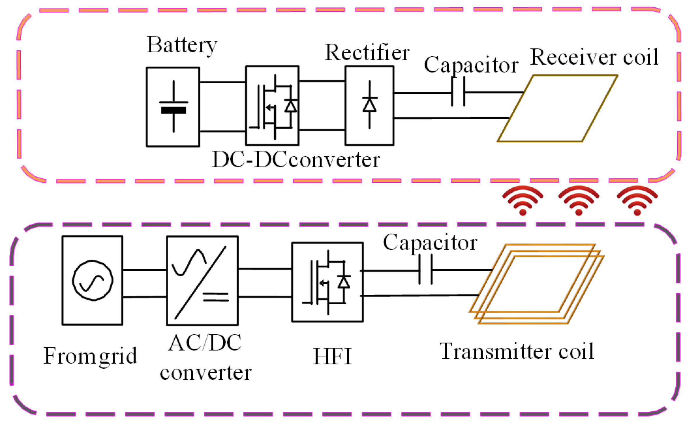
Describing and modeling the dynamic wireless charging system are crucial steps in designing and optimizing the performance of the DWC technology. The DWC system comprises charging infrastructure integrated into the road surface and a receiver unit installed in the electric vehicle (EV), enabling convenient and seamless charging without the necessity of physical connections.
Figure 1 illustrates a block diagram representation of the DWC system. The grid supply is connected to the power factor correction (PFC) rectifier circuit, which is then linked to the high-frequency inverter (HFI). To meet the reactive power demands of coil inductance for generating a substantial magnetic field, the compensation network is connected to both sides of the coil [
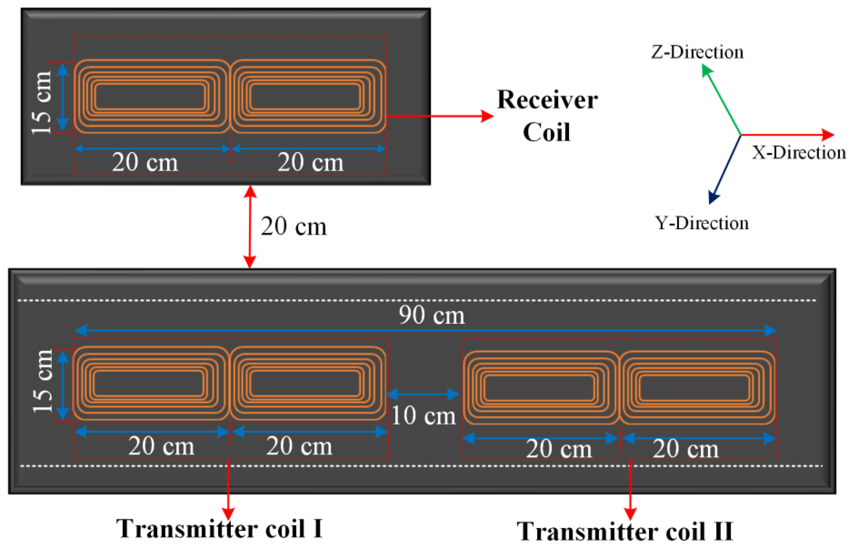
18]. The schematic arrangement for the magnetic coupler is illustrated in
Figure 2. It comprises a pair of transmitter coils and a pair of receiver coils, all sharing identical geometric properties of double-D nature. Double-D coil structures find widespread application in the dynamic wireless charging systems of electric vehicles. The transmitting coils are distributed along a 90 cm track, with a separation distance of 10 cm between them.
As shown in
Figure 2, there is an air gap of 20 cm between the transmitting and receiver coils, maintaining their spatial relationship. The choice of air gap distance is tracked from the guidelines provided by the existing well-established SAE J2954 standard [
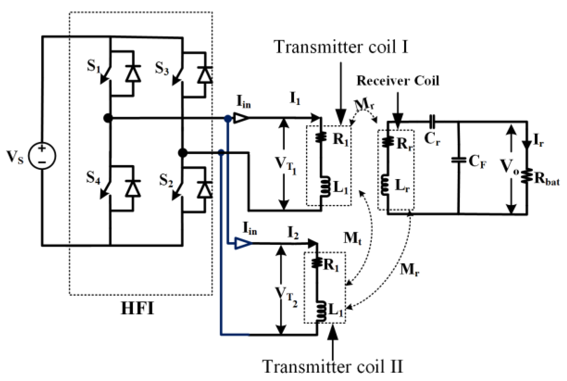
21] for electric vehicles. Ensuring model validity, our investigations are underpinned by rigorous utilization of COMSOL 5.5 and informed by insights from pertinent prior research. The simplified modeling equation describing the DWC system shown in
Figure 3 is presented as follows:
where
and
represent the respective voltages while
I1 and
I2 refer to the currents associated with transmitting coil 1 and 2, respectively. The impedance
ZT is associated with the track coils,
Ir represents the current flowing through the AC battery’s equivalent resistance
Rbat,
j is the complex number, and
is the angular frequency. Additionally,
ZR denotes the impedance represented alongside the receiver coil.
Mt and
Mr are the intra- and inter-mutual inductances between the track coil and pick-up coil. By solving the system of equations represented in Equation (1), the required parameters are obtained for the calculations of efficiency. To simplify the analysis, similar parameters are considered for both of the primary coils, as represented in
Figure 4.
The output voltage (
Vo) and the power transferred (
Po) are given as follows:
From the above analysis, the efficiency can obtained as follows:
where the efficiency of DWC in Equation (5) is presented by considering total losses accompanying magnetic coil systems reported in the literature. In this analysis, emphasis is given to the investigation of power pulsations to enhance the performance the DWC system. The efficiency calculated in this study pertains to the magnetic coupler in the absence of shield and ferrite core materials.
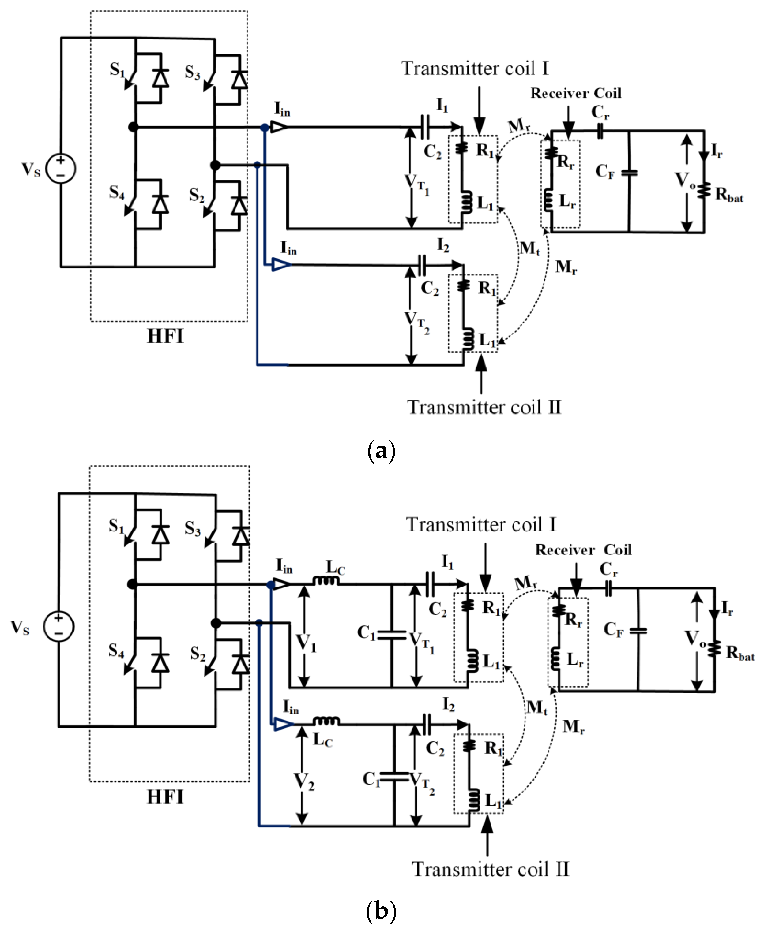
2.2. Configuration of Compensation Schemes
To fulfill the reactive power requirements in wireless charging systems, various compensation circuits are employed [
22]. A comparison of the various basic compensation schemes is represented in
Table 1. Evaluation of the schemes in
Table 1 provides an understanding of compensation systems concerning flux density, mutual inductance, power transferred, and reactive power requirements. This paper’s analysis focuses on evaluating two prominent compensation topologies: series–series (SS) and inductor (L)–capacitor (C)–capacitor (C)–series (LCC-S) compensation. In series–series compensation, a compensating capacitor is connected in series with the self-inductance in both the primary and secondary sides. Conversely, LCC-S compensation is specifically designed to address multiloading scenarios, utilizing an LCC circuit connected with the primary coil’s inductance and a single capacitor connected in series with the secondary coil’s inductance, as shown in
Figure 4a,b.
3. Analysis of Mutual Inductance
Mutual inductance, which represents the magnetic coupling between the charging infrastructure and the receiver unit, has a significant impact on power transfer efficiency. Understanding the characteristics of mutual inductance is essential for augmenting the design and operation of DWC systems, ultimately enhancing the charging performance and user experience of EVs. Modeling and simulation techniques are employed to analyze and predict the mutual inductance in DWC systems. Mathematical models are developed considering the geometrical parameters of the coils, such as their sizes, shapes, and orientations. Finite element analysis (FEA) or other numerical methods are utilized to simulate the electromagnetic behavior and predict the mutual inductance [
23,
24].
To ascertain the mutual inductance between two double-D coils within a dynamic wireless charging system, several analytical formulas have been documented in the existing literature [
15,
25,
26,
27]. Within this analysis, a progressive methodology is harnessed in tandem with axisymmetric finite element analysis. This approach yields a mirrored depiction of the scenario upon encountering a polarity reversal during motion. Subsequently, the analysis of mutual inductance (
MA), taking into account misalignment factors such as longitudinal distance, lateral distance, and air gap distance between the coils, is presented below.
Let μ₀ represent the permeability of free space, while l₁ and l₂ denote the lengths of the two coils. The coupling factor,
, which relies on the incremental longitudinal distance (
dx), incremental lateral distance (
dy), and incremental air gap distance (
dz) between the coils, can be expressed as follows:
The angles , represent the angles between the longitudinal axis and the lateral axis of the transmitter and receiver coils, respectively. To simplify the analysis, the angle is considered as properly aligned, i.e., = 0 (no longitudinal misalignment) and = 0 (no lateral misalignment). Nevertheless, the computation of mutual inductance utilizing the aforementioned method is restricted to 2D asymmetric geometries and becomes arduous when applied to substantial systems. However, the method assumes that the coils possess similar geometry along their common axis. It assumes a homogeneous medium between the coils during operation. Additionally, it uses a simplified constant permeability for free space. The real-world limitations include different coil shapes, complexities in calculating the coupling factor, system variability, environmental factors, and the presence of ferrous materials that can affect mutual inductance.
3.1. Variation in Mutual Inductance with SS Compensation
The series–series (SS) compensation technique is one of the methods employed to compensate for variations in mutual inductance in DWC systems. SS compensation involves the addition of compensation elements in series with the primary and secondary coils. These compensation elements help regulate power transfer and adjust the mutual inductance to maintain a stable and efficient charging process. SS compensation offers several benefits in dynamic wireless charging systems. It helps mitigate variations in mutual inductance caused by misalignment or changes in coil positions, ensuring stable and efficient power transfer [
28]. By regulating the power transfer parameters, SS compensation enhances charging efficiency, reduces power losses, and improves the overall performance of DWC systems.
3.2. Variation in Mutual Inductance with LCC-S Compensation
LCC-S compensation is a technique used to compensate for variations in mutual inductance in DWC systems. It involves the addition of a compensation network in series with the primary or secondary coil. LCC-S compensation techniques provide a viable solution to mitigate variations in mutual inductance, ensuring stable and efficient power transfer. In addition, it also ensures robust performance through enhanced design flexibility and adaptability.
5. Results and Discussion
Finite element analysis (FEA) is a sophisticated and extensively employed tool in engineering for design and analysis purposes. FEA analysis of magnetic coils primarily entails an in-depth examination of a coil’s flux density and geometry. To initiate this process, a 2D model of the coil was meticulously constructed through the utilization of cutting-edge COMSOL 5.5 software as per the dimensions shown in
Figure 2. The software facilitates the precise simulation and assessment of a coil’s magnetic properties, allowing for comprehensive analysis and coil design. By leveraging FEA and the computational power of COMSOL 5.5 software, valuable insights can be drawn for analysis of the flux density of the magnetic coupler. The details of the simulation are represented in
Table 2.
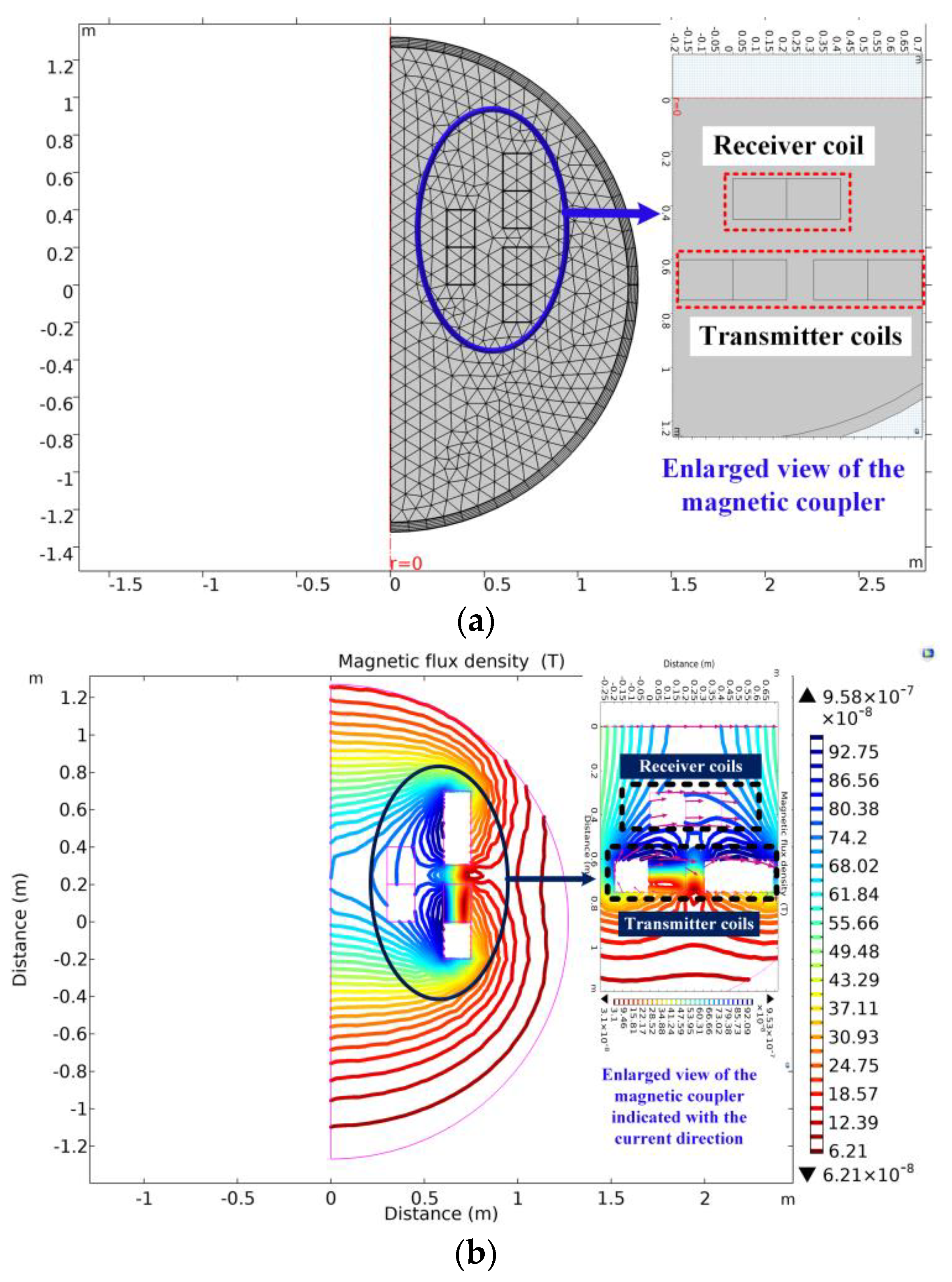
FEA analysis of the magnetic coupler was conducted using COMSOL software, and the results obtained include the meshing diagram shown in
Figure 5a, which illustrates the discretization of the magnetic coupler geometry into small elements for numerical analysis. It shows how the computational mesh is generated to approximate the physical domain. In addition to this,
Figure 5a provides an enlarged view of the magnetic coupler, offering a more detailed exploration of its intricate design and functional components. The contour map of the flux density distribution shown in
Figure 5b exhibits a visual representation of how the magnetic flux is distributed throughout the magnetic coupler. It uses color-coded contours to indicate the magnitude and direction of the flux density at different locations. This map allows for regions of high and low flux density to be identified, providing a way of estimating mutual inductance. Similarly,
Figure 5b provides an expanded view of the magnetic coupler, offering a detailed perspective of the current distribution within the coupler, clearly denoted by the arrow marker.
The importance of FEA in determining flux density distribution, through evaluation of mutual inductance including accuracy, flexibility, visualization, optimization potential, and other parameters, makes it a powerful tool for assessing the performance of magnetic couplers in various applications. The design parameters of the DWC system used are presented in
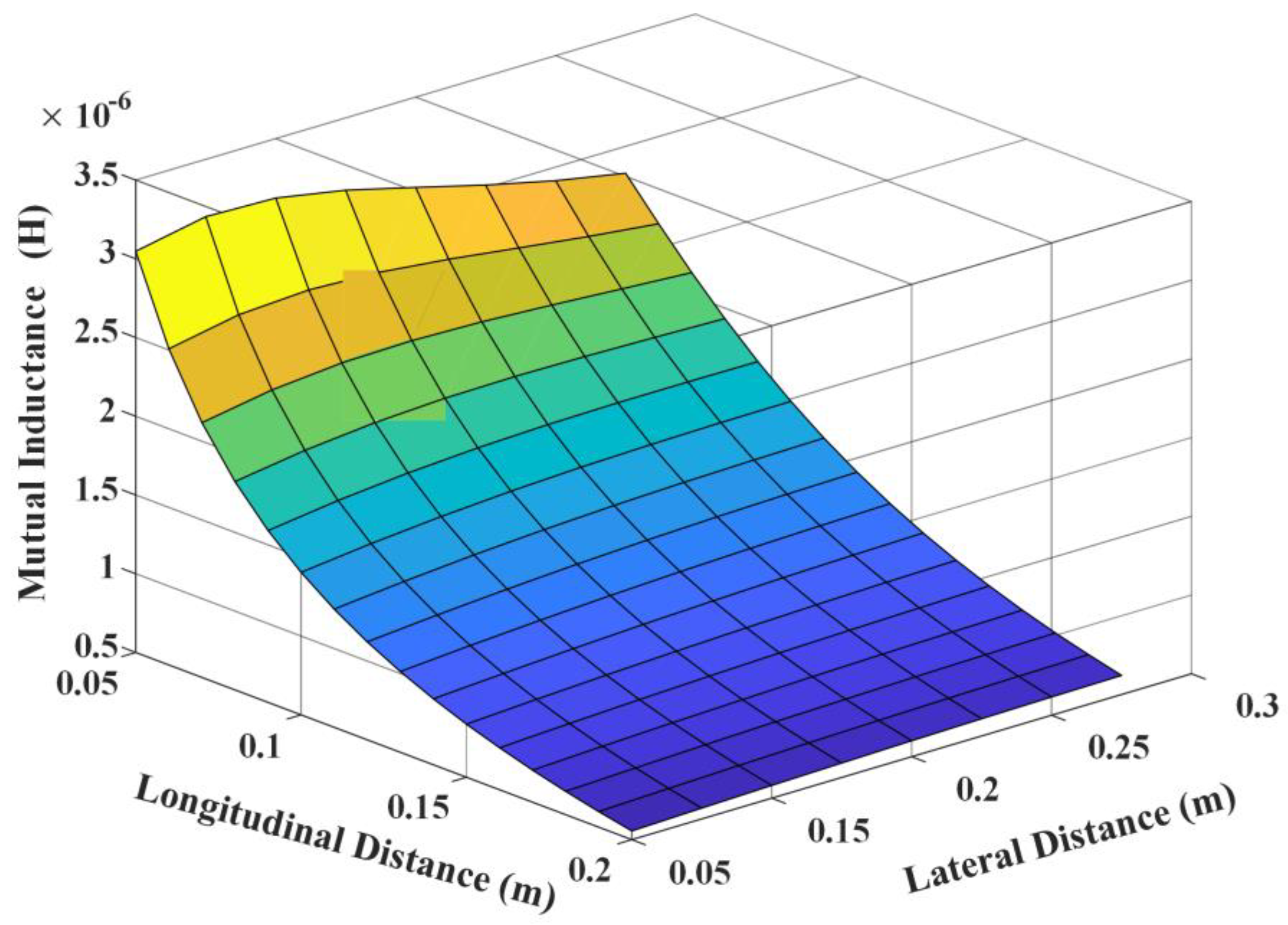
Table 3. Relying solely on 2D models and making assumptions during finite element analysis (FEA) can result in generalization of the intricate nature of real-world phenomena, possibly causing inaccuracies in results. The established thresholds for misalignment and air gap distance stem from FEA-derived values, which might diverge from actual practical situations. The primary scope of the investigation revolves around magnetic couplers, leaving aside various other conceivable complex real-time scenarios. The plot for the variation in mutual inductance is shown in
Figure 6 and clearly illustrates the relationship between misalignment and mutual inductance. As the misalignment increases beyond the specified limits, the mutual inductance tends to decrease. This decrease can be attributed to the reduced magnetic coupling between the coils due to the misalignment, leading to a decrease in the effective coupling area.
By identifying the threshold values of misalignment, namely 10 cm in the longitudinal direction and 5 cm in the lateral direction with constant air gap distance, this research highlights the critical alignment requirements for maintaining good mutual inductance. Adhering to these limits is crucial for achieving efficient power transfer and consistent operation in applications relying on magnetic coupling. It is evident from
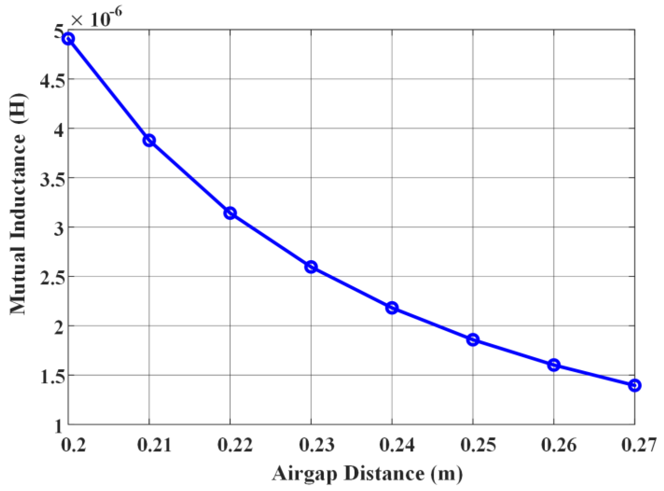
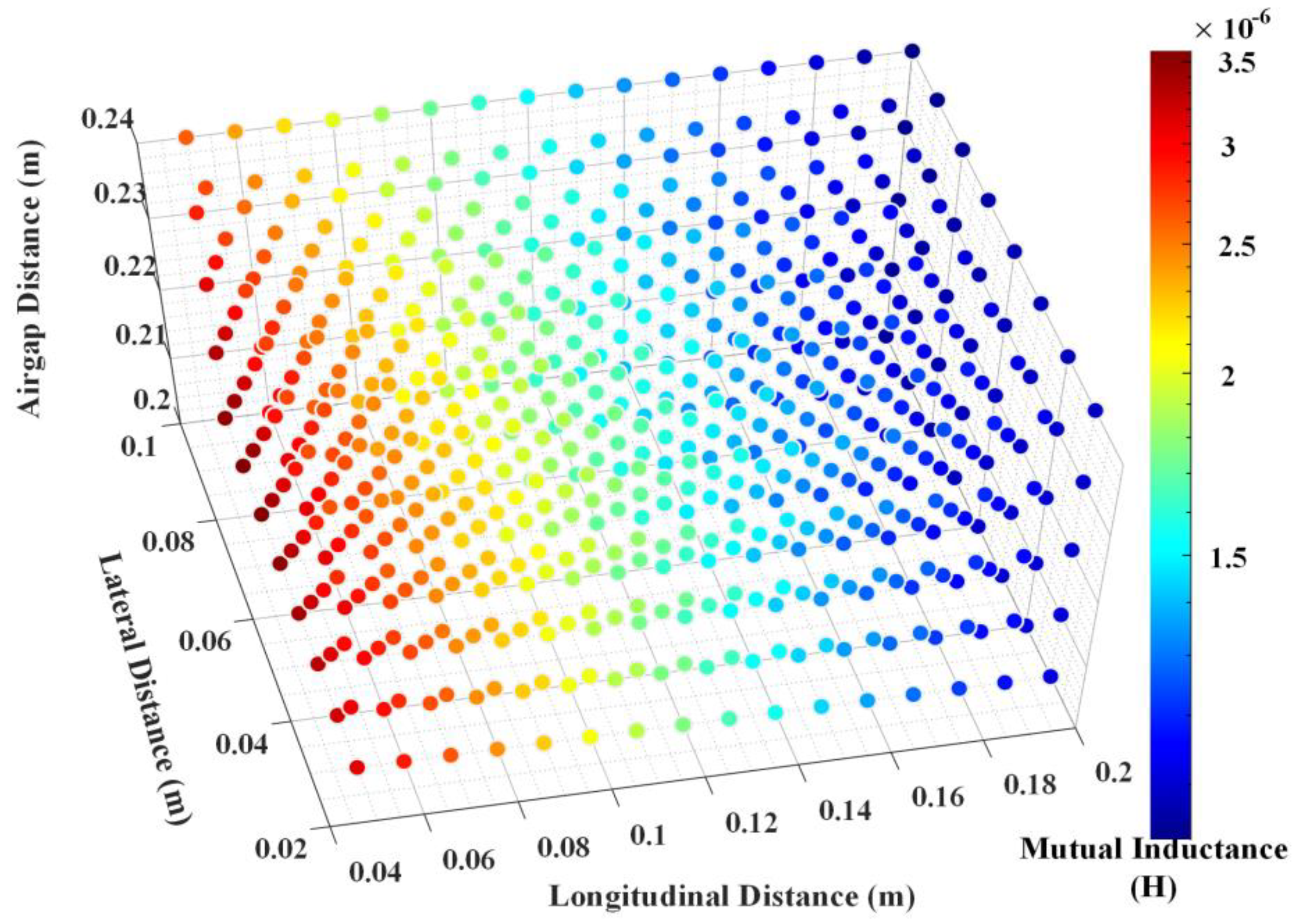
Figure 7 that slight variations in air gap distance will have a great impact on mutual inductance. The conclusive findings, shown in
Figure 8, indicate that mutual inductance exhibits a noticeable pattern concerning the longitudinal distance, lateral distance, and air gap distance between the coils’ coordinates. The scatter plot demonstrates that certain positions in the space yield higher mutual inductance values, while others result in lower values. Henceforth,
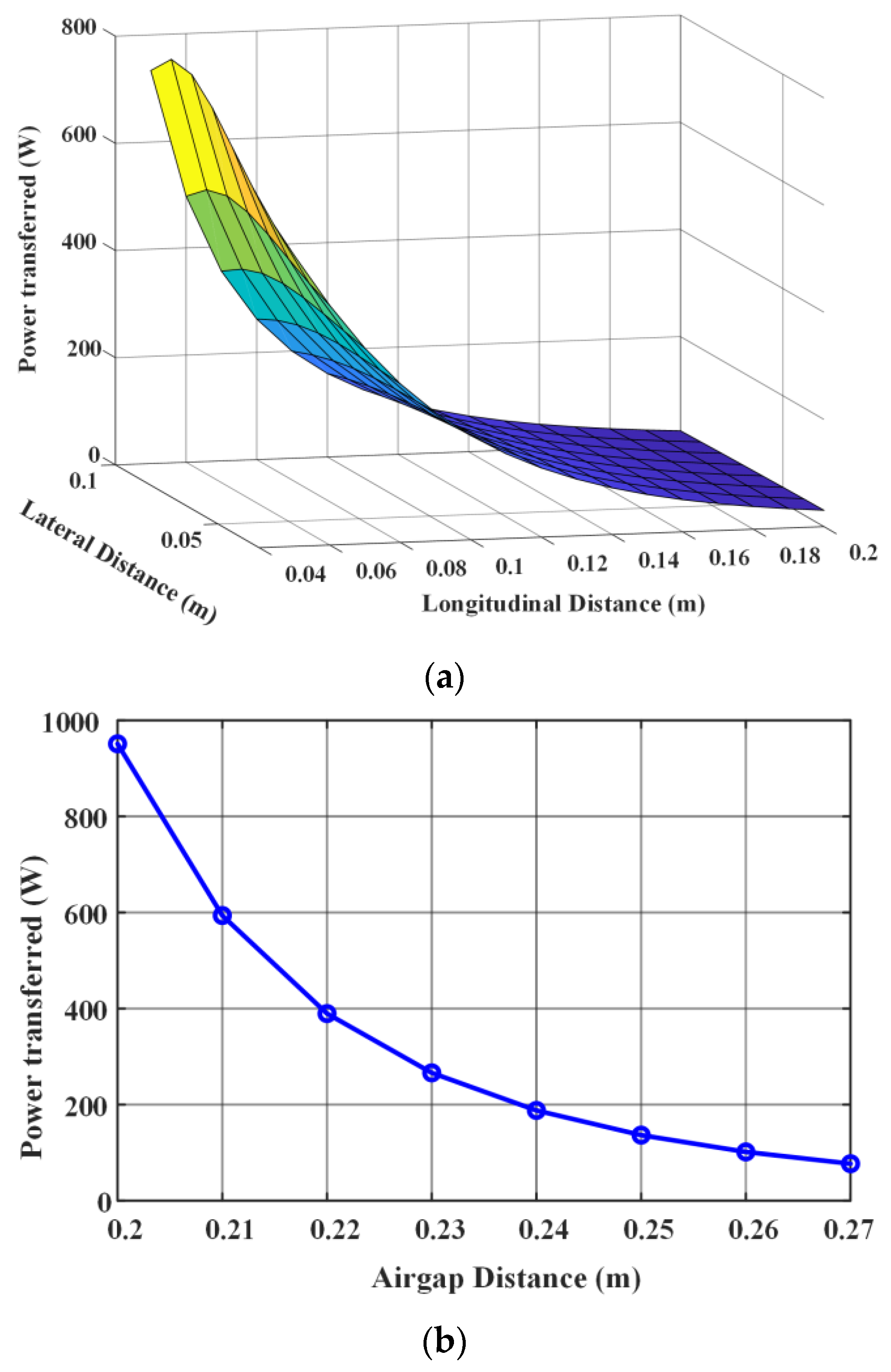
Figure 8 demonstrates the wide range of implicit practical scenarios. The results obtained from the plot of the variation in power transfer in both the longitudinal and lateral directions, as well as the air gap direction, are shown in
Figure 9a,b, which indicates a significant decrease in power transfer beyond a misalignment of 10 cm in the longitudinal direction and 5 cm in the lateral direction. As the air gap distance between the transmitter and receiver coils exceeds a certain threshold, there is a notable decline in power transfer.
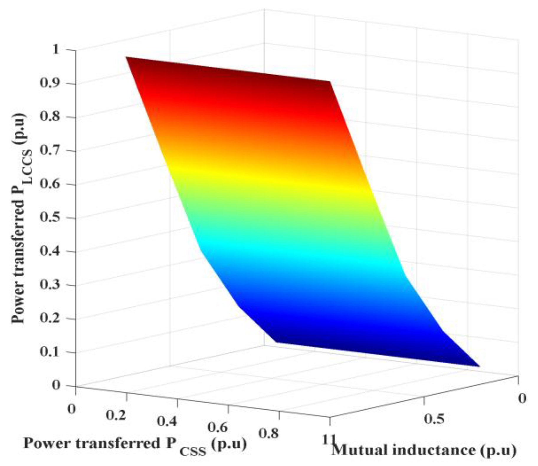
The surface plot in
Figure 10 shows the relationship between mutual inductance, power transferred in the SS compensation system, and power transferred in the LCC-S compensation system. Increasing mutual inductance generally leads to higher power transfer. The LCC-S compensation system tends to transfer more power compared to the SS compensation system, as shown in
Table 4.
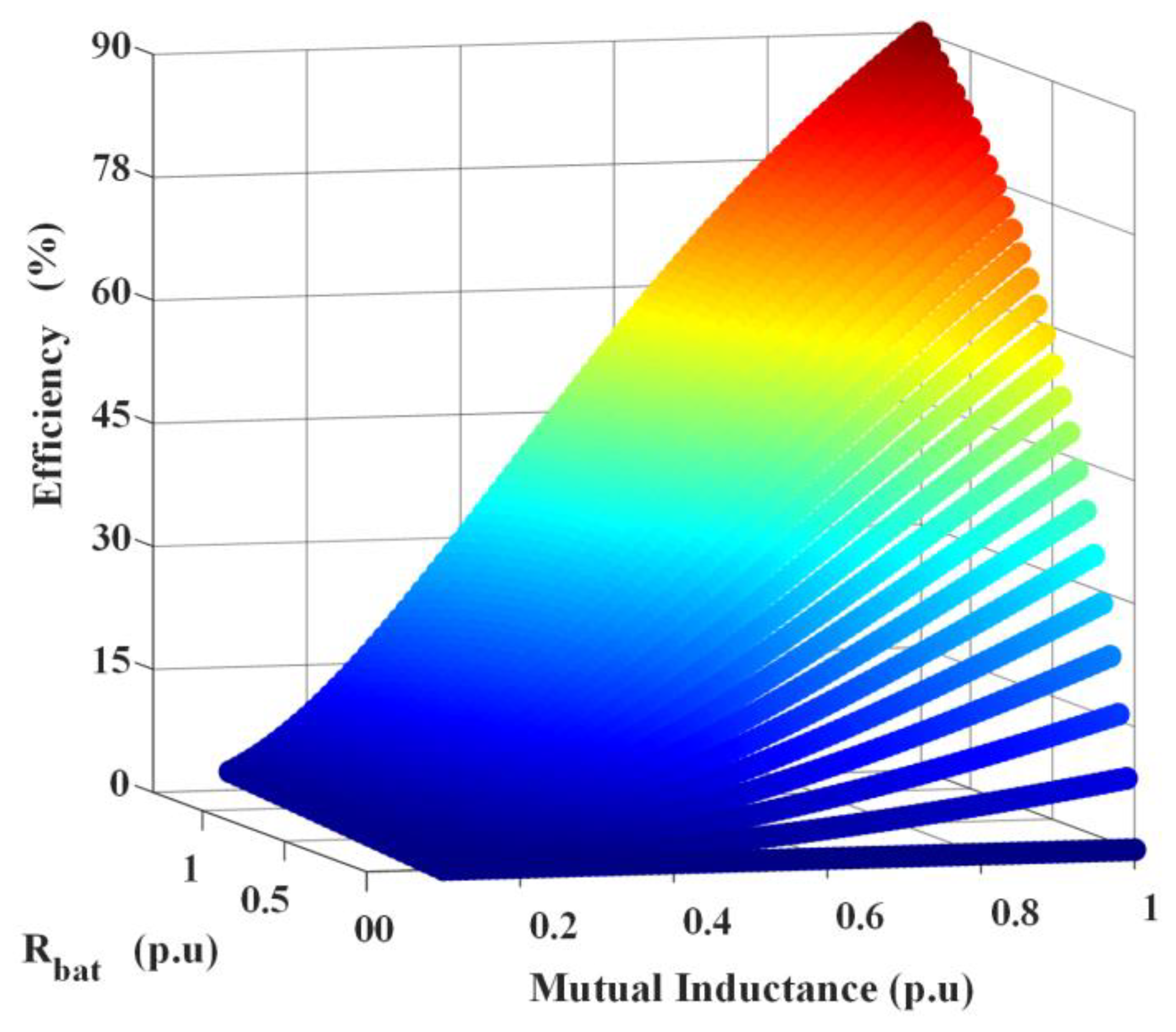
The surface plot analysis is shown in
Figure 11, which demonstrates that higher mutual inductance improves the efficiency of the DWC system while increased ac-equivalent resistance of the battery leads to decreased efficiency. Considering the inevitable resistance variation, careful selection of mutual inductance is necessary to mitigate the negative impact and achieve higher efficiency. In essence, our study immerses itself in FEA, harnessing the power of COMSOL 5.5 to intricately probe magnetic coupler configurations. FEA unveils the intricacies of flux density, offering accurate insights for mutual inductance determination across scenarios while also exploring efficiency gains. Moreover, the spotlight on the impact of alignment in relation to mutual inductance outlines pivotal thresholds.
6. Conclusions
In summary, this comprehensive investigation extensively explores the crucial aspects of power pulsation, mutual inductances, and overall system efficiency in dynamic wireless charging (DWC) systems for electric vehicles. By meticulously analyzing longitudinal, lateral, and air gap distances as key parameters, this research underscores the need to enhance these factors to improve system performance. Through rigorous simulations conducted with COMSOL and MATLAB, the findings emphasize the significance of improving alignment issues, with a suggested typical limit of 10 cm longitudinal and 5 cm lateral misalignment for achieving reduced power pulsations. Furthermore, the evaluation of mutual inductance offers valuable insights into selecting appropriate compensating elements. Ultimately, this investigation provides a practical and insightful roadmap for the efficient implementation of DWC systems, culminating in the notable observation that the LCC-S compensation system exhibits superior power transfer compared to the SS compensation system. This refined exploration not only contributes to the advanced comprehension of dynamic wireless charging systems but also lays the groundwork for their optimization, helping to reshape the landscape of electric vehicle charging.


 ,
, 


