Article

A Vehicle Crash Simulator Using Digital Twin Technology for Synthesizing Simulation and Graphical Models

1
Timsolution, Ulsan 44538, Republic of Korea
2
Department of Information Security, Seoul Women’s University, Seoul 01797, Republic of Korea
*
Author to whom correspondence should be addressed.
Vehicles 2023, 5(3), 1046-1059; https://doi.org/10.3390/vehicles5030057
Submission received: 11 July 2023 / Revised: 11 August 2023 / Accepted: 25 August 2023 / Published: 28 August 2023
(This article belongs to the Special Issue Recent Developments in the Intelligent Transportation System (ITS))

Abstract

:
Computer vehicle simulators are used to model real-world situations to overcome time and cost limitations. The vehicle simulators provide virtual scenarios for real-world driving. Although the existing simulators precisely observe movement on the basis of good-quality graphics, they focus on a few driving vehicles instead of accident simulation. In addition, it is difficult to represent vehicle collisions. We propose a vehicle crash simulator with simulation and animation components. The proposed simulator synthesizes and simulates models of vehicles and environments. The simulator animates corresponding to the simulation through the execution results. The simulation results validate that the proposed simulator provides collision and non-collision results according to the speed of two vehicles at an intersection.

1. Introduction

In the automobile industry, software technology has led to the emergence of vehicle simulators for fuel efficiency, vehicle collision, and vehicle control [1,2,3]. A computer simulation is a technique for modeling and experimenting with real-world situations. Simulations can overcome the limitations of time and cost in general and can analyze various situations. The computer software for simulating vehicle crash mechanics provides comparisons of simulation results with the expression result to indicate the degree of accuracy. Therefore, simulators must possess basic vehicle crash simulation capabilities [1,4,5].
The crash simulation for reproducing a traffic accident is a mathematical formula obtained through numerous actual vehicle-based experiment data and the collision and kinematics of a vehicle. The existing simulators are based on repeated input of vehicle motion conditions and user driving behavior before the crash based on accident data such as vehicle specifications, damage status, final stop position, and road marks at the accident site. After deriving the simulation results, an optimal collision situation and an understanding of the activity following the collision are considered for analysis.
Although software-based simulation can represent vehicle crashes in a virtual environment, most simulation results are output as text, making it difficult for non-developers to understand verification and validation. To improve these problems, it is necessary to visually express the simulation results [6,7,8]. Animation software is a dynamic visual form of graphic object output of a target system to increase understanding [9,10,11]. Therefore, an animation-based simulation makes it easier to verify the model by visually representing the simulation process, improving understanding, and increasing clarity. Simulation visualization as a form of output is widely used in various fields. Animation is also used to express the results of a computer simulation. In addition, to accomplish a reliable simulation, the simulation model and the moving graphic object must be connected and expressed intuitively. Researchers have proposed several simulators to represent both simulation and animation in vehicle driving or vehicle crashes [12,13,14,15,16].
In this paper, we propose a simulator that mutually complements the simulation and animation components to provide vehicle crash scenarios. Our proposed simulator synthesizes and simulates models selected from our repository and animates the simulation results. The model repository stores vehicle and road map models in two bases. The proposed simulator synthesizes the vehicle model developed by Simpy [17] and the road map model applying the Lambda function [18,19] to describe a vehicle crash. In the proposed simulator, the simulation component performs the synthesized model through the Simpy engine. Next, the animation component receives the simulation results and reenacts the vehicle crash. Thus, our simulator combines the two components to effectively illustrate vehicle crash scenarios.
The main contributions of this paper are as follows:
  • Simpy-based simulation for vehicle collisions,
  • Unity-based animation for visualization of the collision using the simulation results.
The remainder of this paper is organized as follows: Section 2 introduces vehicle driving and simulators. The problem statements are discussed in Section 3. We offer a detailed description of the proposed simulator in Section 4. In Section 5, we present a performance evaluation of the proposed simulator. We draw conclusions at the end of this paper.

2. Related Work

This section introduces vehicle driving simulators in Section 2.1 and crash simulators in Section 2.2 for comparisons to our simulators.

2.1. Vehicle Driving Simulators

Various vehicle simulators are being developed for a wide range of purposes, such as accident collision simulation, tests of self-driving vehicles, and environment collection. The typical existing simulators include the LG Autonomous Driving (AD) Simulator [12], NVIDIA Drive Sim [13], the Morai Simulator [14], Microsoft AirSim [15], and CarSim [16]. Table 1 shows a comparison of typical existing vehicle simulators.
The LG AD Simulator is a simulation software that provides development and testing for vehicle driving software systems. When the LG simulator is used in the test pipeline, it is possible to reduce costs and assure a wide range of test coverage. This simulator is a Unity high-definition render pipeline (HDRP)-based photorealistic simulation that creates a real-world digital environment identical to the real environment. The simulator provides autonomous driving test and verification (HIL; hardware-in-the-loop, VIL; vehicle-in-the-loop), autonomous driving software development (SIL; software-in-the-loop), and data generation. It can be used for running training, mobility services, sensor and vehicle setup, system-on-chip (SoC) design and testing, and more.
NVIDIA Drive Sim provides a safe, scalable, and cost-effective way to bring autonomous vehicles onto the road using physically accurate simulation. The program leverages NVIDIA core technologies to provide a powerful cloud-based computing platform that enables the creation of a wide range of real-world scenarios for vehicle development and validation. In addition, it provides virtual performance for generating datasets for training a vehicle’s recognition system or for testing a vehicle’s decision-making process, as well as to account for extreme cases. The simulation can be connected to vehicle stacks in SIL or HIL configurations to test system integration. It evaluates how real humans interact with the vehicle’s technology.
The Morai Simulator provides simulation environments, sensor models, and virtual test environments for vehicles based on high fidelity. The simulator includes precision map-based digital twin technology, test scenario generation, mixed-reality test methodology (i.e., VIL), vehicle simulation technology, environmental data generation technology, and distributed computation technology.
AirSim is a simulator for vehicles and drones based on the Unreal Engine [20] developed by Microsoft. This simulator is open-source and cross-platform-based, and it supports flight controllers such as PX4 Autopilot [21] and HIL simulation through PX4 to represent physically and visually realistic simulations. Moreover, it was developed as an Unreal Plugin that can simply be used in any Unreal environment. The simulator can experiment with autonomous driving using deep learning, computer vision, and reinforcement learning algorithms for autonomous vehicles. It provides APIs to retrieve data and control vehicles in a platform-independent manner.
CarSim is a software tool that simulates the dynamic behavior of passenger vehicles and light trucks. The simulator uses a 3D multibody dynamics model to accurately reproduce the physics of a vehicle in response to the driver and automation including steering, throttle, braking, and gear shifting. The simulator’s environmental conditions can include 3D ground and road surfaces, as well as aerodynamic and wind effects. This simulator is the universally preferred tool for analyzing vehicle dynamics, developing active controllers, calculating vehicle performance characteristics, and engineering next-generation active safety systems.
As shown in Table 1, although these simulators provide reality-based simulation and excellent 3D graphics, it is difficult to simulate a crash of two vehicles according to various scenarios. In addition, the existing simulators rarely experiment by separating the simulation and animation components to create various collision scenarios between the vehicles.

2.2. Vehicle Crash Simulators

EDVAP (Engineering Dynamics Vehicle Analysis Package) and PC-CRASH are the most widely used commercial programs worldwide for vehicle crash simulators. In EDVAP, the collision model applies the EBS (equivalent barrier speed) to obtain the effective collision speed from the deformed state of the vehicle. The model reconstructs motion situations such as angles before and after collision and moving distance using the law of conservation of momentum and energy.
PC-Crash is a commercialized traffic accident reproduction simulator that applies 2D and 3D collision models based on Newton’s laws of motion. The simulator can reproduce a full impact in which the two vehicles reach a common speed and a sliding impact in which the two vehicles do not reach a common speed. In addition, the simulator uses EES (equivalent energy speed) using the point of impact and the damage depth of the vehicle relative to the location of impact and the energy loss of both vehicles due to the damage. It is possible to simulate various collisions such as vehicle-to-vehicle accidents, pedestrian accidents, overturning accidents, motorcycle accidents, trailer accidents, and obstacle collision experiments.
The commercial simulators are less accessible because of payment of expenses as compared to most open software projects.

3. Problem Statement

In this section, three drawbacks of the existing simulators are described, and three improvements to the proposed simulator are introduced.
Although these are efficient vehicle simulators based on their excellent graphics, they have the following drawbacks:
  • The existing vehicle simulators are aimed at safe driving, and it is difficult to simulate collisions between vehicles. A collision between two vehicles is affected by various environmental variables such as vehicle size, road condition, and accident scenario. Involvement of these multiple variables complicates simulation of a crash accident on the basis of a slight change in the value of one variable (e.g., an increase in vehicle speed by 10 km).
  • The existing simulators can only simulate driving in vehicles and environments specified by their developers. Although some simulators use open software policies, limited situations can be simulated.
  • Most simulators focus on 3D graphics for animation. However, simulators should also be able to predict an accident on the basis of specific parameters and iterative analysis. Thus, simulation and animation must complement each other, such as in digital twin technology.
To solve these problems, three corresponding improvements are proposed:
  • Our proposed simulator considers accident characteristics by applying models saved in our model repository. Users can select pre-implemented models from the repository and run a synthesized model to simulate various vehicle crash accidents. The result of the executed simulation is displayed visually as an animation.
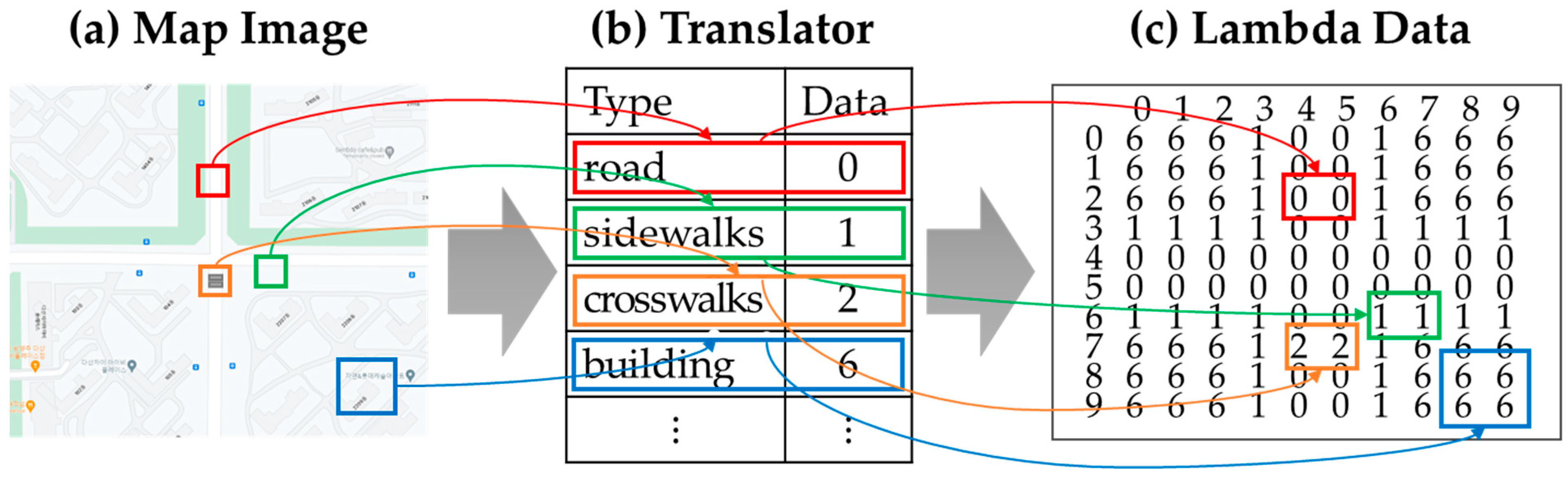
  • The proposed simulator can be directly developed by the users with Simpy-based vehicle models and Lambda-based road map models to simulate various crash accidents. In addition, the models can be freely modified from each base in the repository component.
  • Our simulator synthesizes models including bases for vehicle crash accidents, simulates them, and displays crash animations before and after the collision. The simulator defines the state change of an event for animation and the information to transmit it to the animation. In addition, the animation is configured in the same situation as the model synthesized from the model base.

4. Proposed Simulator
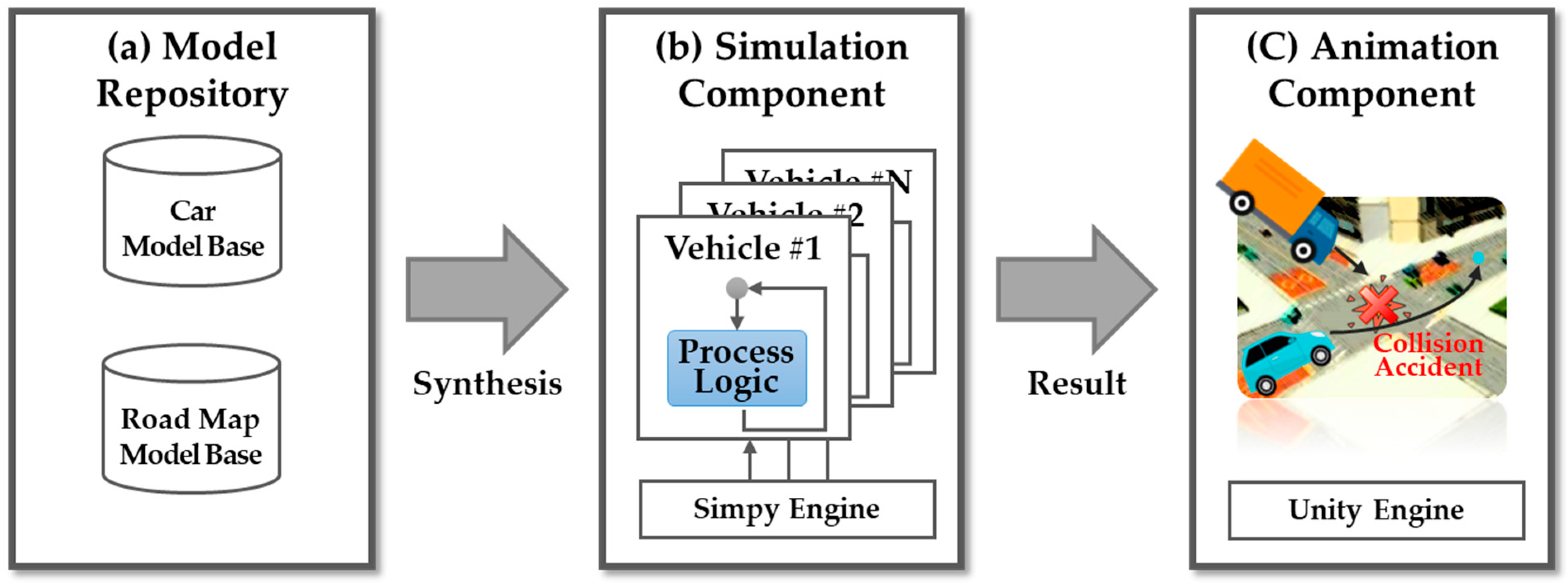
In this section, the proposed simulator is detailed. Our proposal overview is presented in Section 4.1, and the detailed procedures of the simulator are given in Section 4.2.

4.1. Overview

Our simulator mutually complements the simulation component and the animation component to predict vehicle collision. The proposed simulator synthesizes and simulates models selected from our repository component and then animates the results. The repository component consists of two model bases: vehicle and road map. In the model bases, a model is selected and synthesized to construct a target collision accident. Our simulation component runs the synthesized model through the Simpy engine, and our animation component uses the simulation results to recreate the vehicle accident.
Figure 1 shows an overview of our proposed simulator, which comprises a repository component, simulation component, and animation component. The proposed simulator executes three phases as follows:
  • Model repository: In this repository, the two model bases are vehicles and road maps. Simpy-based discrete-event models for vehicles consider behavioral and procedural characteristics and are synthesized to generate a final simulation model.
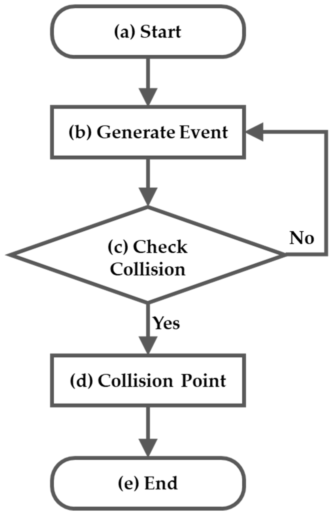
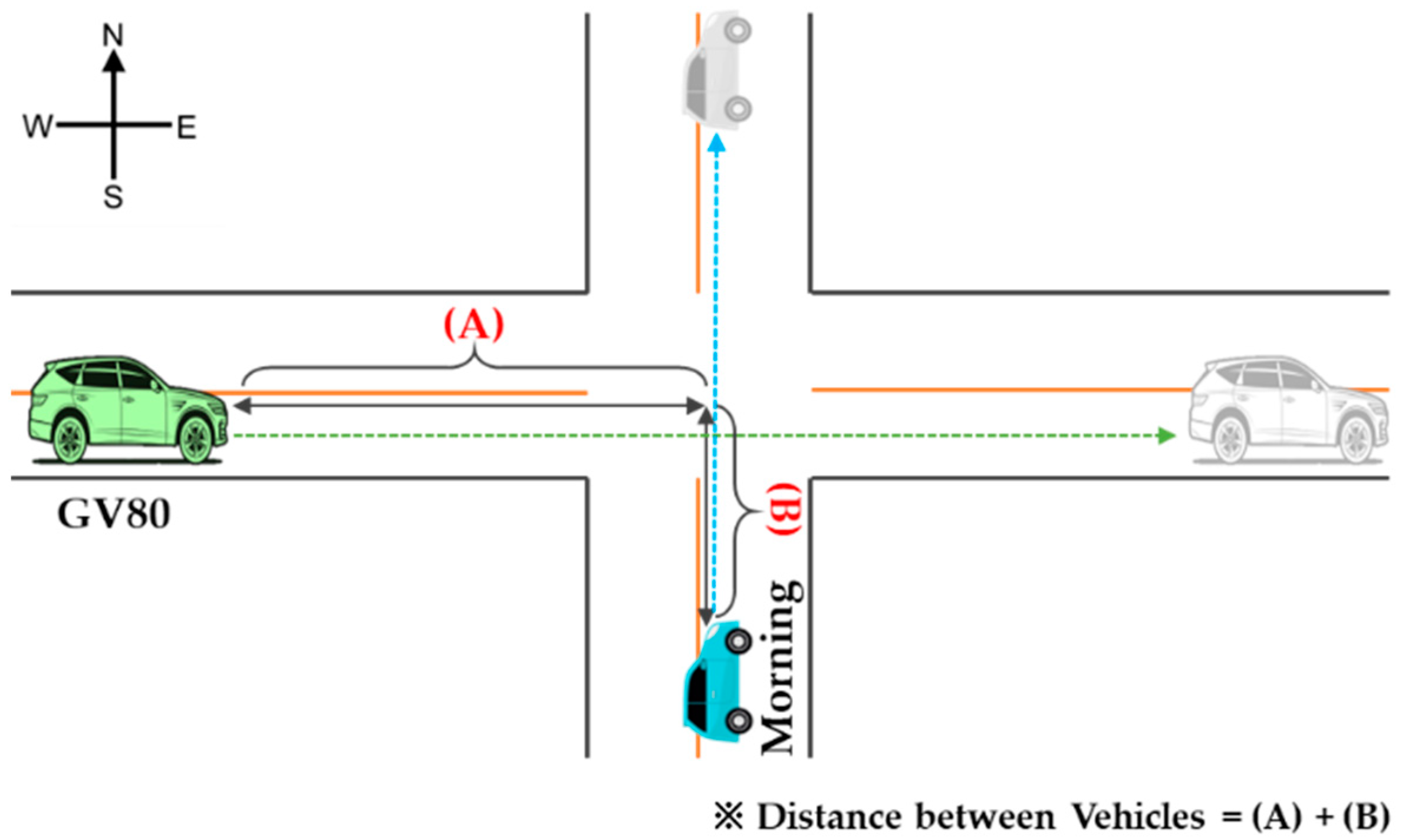
  • Simulation component: This component runs the synthesized model through the Simpy engine and forwards the events generated to the model. The vehicle simulation model behavior is changed at regular intervals (e.g., simulation time). The execution of the component is repeated according to the state variable of the model until the distance between the two vehicles is 0. Simulation results are transmitted to the animation elements using JSON templates.
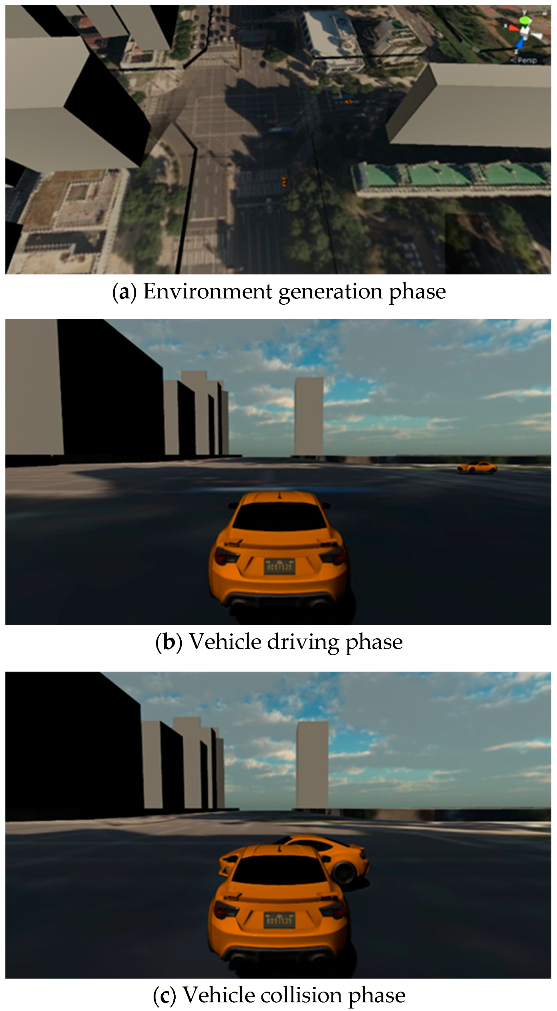
  • Animation component: This component parses the JSON files received from the simulation component and creates and executes a 3D model according to the parsed result.
Therefore, the proposed simulator mutually complements the simulation and animation components to inform vehicle crash prevention after synthesizing the selected models.

4.2. Detailed Procedure

Our simulator includes three components: model repository, simulation, and animation. The simulator is as follows:
P r o p o s e d   S i m u l a t o r = M o d e l   R e p o s i t o r y , S i m u l a t i o n , A n i m a t i o n .
In the model repository, our proposed simulator provides the set of vehicle models and environment models for synthesizing a simulation model. In the simulation component (Simulation), our simulator synthesizes the models selected from the model repository and runs the synthesized model. The simulator extracts the simulation result. In the animation component (Animation), it parses the received result and creates a 3D object corresponding to each model. Each object is executed through the Unity engine.

4.2.1. Model Repository

This repository consists of two model bases: vehicles and environment. The vehicle model is based on Simpy, a process-oriented discrete-event simulation written in Python. The process-oriented simulation is lightweight, easy-to-use, and allows quick learning for use.
Simpy’s engine is composed of three parts: process, environment, and resource. The process creates a generator method that yields an event instance by modeling a generic agent. The environment manages event scheduling, event processing, and time management. The resource provides preemption of processes and shared resources (e.g., number of processes). The proposed simulator adopts Simpy-based simulation to design and execute the models due to its systematic modularization and ease of use.
The vehicle model defines parameters related to driving and collision. The parameters are empty weight, length, vehicle width, engine type, and tire size. For example, with a Hyundai Genesis GV80 [22], an empty weight of 2100 kg, length of 4945 mm, width of 1975 mm, 2.5 gasoline turbo engine, and 22 inch tires are defined.
Figure 2 shows the collision location of the two vehicles based on 12 vehicle points, as proposed in [23]. Damage is predicted in at least at one point in the event of an accident between two vehicles. For example, suppose that two vehicles are traveling on a straight road. When the preceding vehicle stops suddenly and the following vehicle collides with it, the preceding vehicle suffers damage at point 6, and the following vehicle suffers damage at point 12.
The environment model uses lambda data for various vehicle crash environments. After selecting a point (e.g., intersection, curved road) on the map, the points are converted into lambda expressions. Figure 3 shows our map translator of the environment model to convert to lambda data. In the lambda data, 0 represents roads, 1 represents sidewalks, 2 represents crosswalks, 6 represents buildings, etc. The converted lambda expressions represent the vehicle movement during simulation execution, considering the simulation time and speed.
In the model repository, the vehicle models exist in the form of Python classes, and environment models exist as lambda files. The two files are merged by a user in the main function of Python.

4.2.2. Simulation Component

Our simulation component creates a whole simulation model by synthesizing the vehicle and environment models defined in the model repository. The whole model receives discrete events from the Simpy engine, changes the state variables of the vehicle model, and identifies accidental collisions on the road environment.
Figure 4 shows our simulation execution flowchart. When the simulation starts (Figure 4a), the Simpy engine generates an event and JSON data at each time interval and for the state variables (e.g., X and Y axis, driving angle, speed) defined in the models of the two vehicles (Figure 4b). Our simulator calculates the remaining distance between the two vehicles for each state change of the model (Figure 4c). If the remaining distance is zero, the two vehicles collide (Figure 4d) at a vehicle collision. Next, the simulation outputs JSON data to be transmitted to the animation. When the distance between the two vehicles is greater than zero, the simulation continues. Then, our simulator selects one of the 12 points. The pseudo-code used in the check collision step (Figure 4c) of the simulation components is shown in Table 2.
Table 3 shows the checkCollision function for two vehicles. Parameters of the function include pos_1st and pos_2nd for the positions of the two vehicles, which are expressed as position (X, Y). This function calculates a distance between the points (Line 3). When the distance is less than or equal to 1, the function returns a result of TRUE (Lines 5–8).
Table 4 explains the crashPoint function for extracting the collision point. This function first computes the collision point: front, back, left side, or right side (Line 4–22). If the collision point of the vehicle (vehicle_1st) is on the right or left side, the correct side point is calculated (Line 24–33). The side is divided into three points: top right side (RIGHT_TOP_SIDE), right side (RIGHT_SIDE), and bottom right side (RIGHT_BOTTOM_SIDE).
After running a simulation, the simulation component creates a JSON file with the results using two-vehicle models. The JSON file definition is as follows:
JSON = i n i t i a l   p a r a m ,   c r a s h   p a r a m 1 ,   c r a s h   p a r a m 2 ,   c r a s h   p a r a m 3 ,   .
In Equation (1), the JSON file contains the vehicle’s initial parameters and state variables according to time.
i n i t i a l   p a r a m = I D ,   m a s s ,   l e n g t h ,   w i d t h ,   h e i g h t .
In Equation (2), I D is a vehicle model, m a s s is weight, l e n g t h is length, w i d t h is vehicle width, and h e i g h t is height. For example, for a Genesis GV80 vehicle, I D is Genesis GV80, m a s s is 2100, l e n g t h is 494, w i d t h is 197, and h e i g h t is 171.
The simulation component produces state variables according to the time to reproduce the accident crash in crash param, defined as follows:
c r a s h   p a r a m N = I D ,   s p e e d ,   s t e e r i n g ,   p o s i t i o n   ( x ,   y ) .
In Equation (3), ID is a vehicle model and s p e e d is the speed of the vehicle. This value calculates the amount of impact and the moving position of the vehicle. The s t e e r i n g variable represents the vehicle direction (i.e., 0 is upward and rotates clockwise) and computes the movement path of the vehicle and the collision location. The p o s i t i o n variable indicates the position (x-axis, y-axis) of the vehicle for calculating its future path. The simulation component creates a JSON file and forwards it to the animation component.
Equation (4) shows the vehicle model function, where X is the input event set of distance values between two vehicles, and Y is the output event set of output values such as occurrence of collision and collision positions of vehicles. δ e x t is the external transition function implemented with the logic in Table 2, Q is the pair of vehicle state and elapsed time since the last event, and λ is the output function to generate output values from Y. The state transition function ( δ e x t ) of the vehicle model represents the collision dynamics.
Vehicle = < X , Y , S , t a , δ e x t , λ > where , S = Collision , Non Collision δ e x t : Q × X S where , Q = s , t e ) s S , t e T 0 , t a s λ : S Y

4.2.3. Animation Component

The animation component is used to visualize the Simpy model state as an output result that expresses movement [24]. This component helps to easily express processes and results of vehicle changes using the Unity engine. In addition, the animation can easily depict the validation of simulation models in model development [24,25].
When our simulator expresses the simulation model as an animation, information for the event schedule and state transition of each event is exchanged as JSON data. Thus, the simulator establishes a complementary relationship between the simulation and animation components. In the simulation visualization, the general-purpose game engine Unity3D is mainly used [26,27,28].
Our simulator uses the Unity3D engine for animation elements to effectively represent the collision of two vehicles. The animation element parses the state information of its vehicle models from JSON data and executes the Unity models.
Figure 5 demonstrates our animation component’s execution in an intersection. In the proposed simulator, the animation component consists of three phases: (1) environment creation, (2) vehicle operation, and (3) vehicle collision. In the (1) environment generation phase (Figure 5a), this component creates graphic objects of the environment such as vehicles and roads (e.g., intersection) received from the simulation’s JSON data. In the (2) driving operation phase (Figure 5b), the target vehicles move according to the order of JSON data in the generated environment. In the (3) vehicle collision phase (Figure 5c), the component shows the collision of two moving vehicles through the data.

5. Simulation Results

We performed a simulation experiment to evaluate the proposed simulator for two vehicles at an intersection. At the intersection, when the traffic light changes from a red light to a green light, a high-speed vehicle (Genesis GV 80) and a slow-moving vehicle (KIA Morning) collide with each other. We use two laws (i.e., acceleration and impulse) of physics for collision in our experiments. The parameters of the two vehicles are shown in Table 4.
Figure 6 illustrates an intersection environment to simulate the collision of two vehicles. A GV80 moves from west to east, and the Morning drives from south to north. The gap distance between the two vehicles is calculated as the sum of the distances from each other around the intersection. Our proposed simulator simulates the collision or non-collision between the GV80 and the Morning according to the change in speed or acceleration in the Morning. We configure two simulation environments.
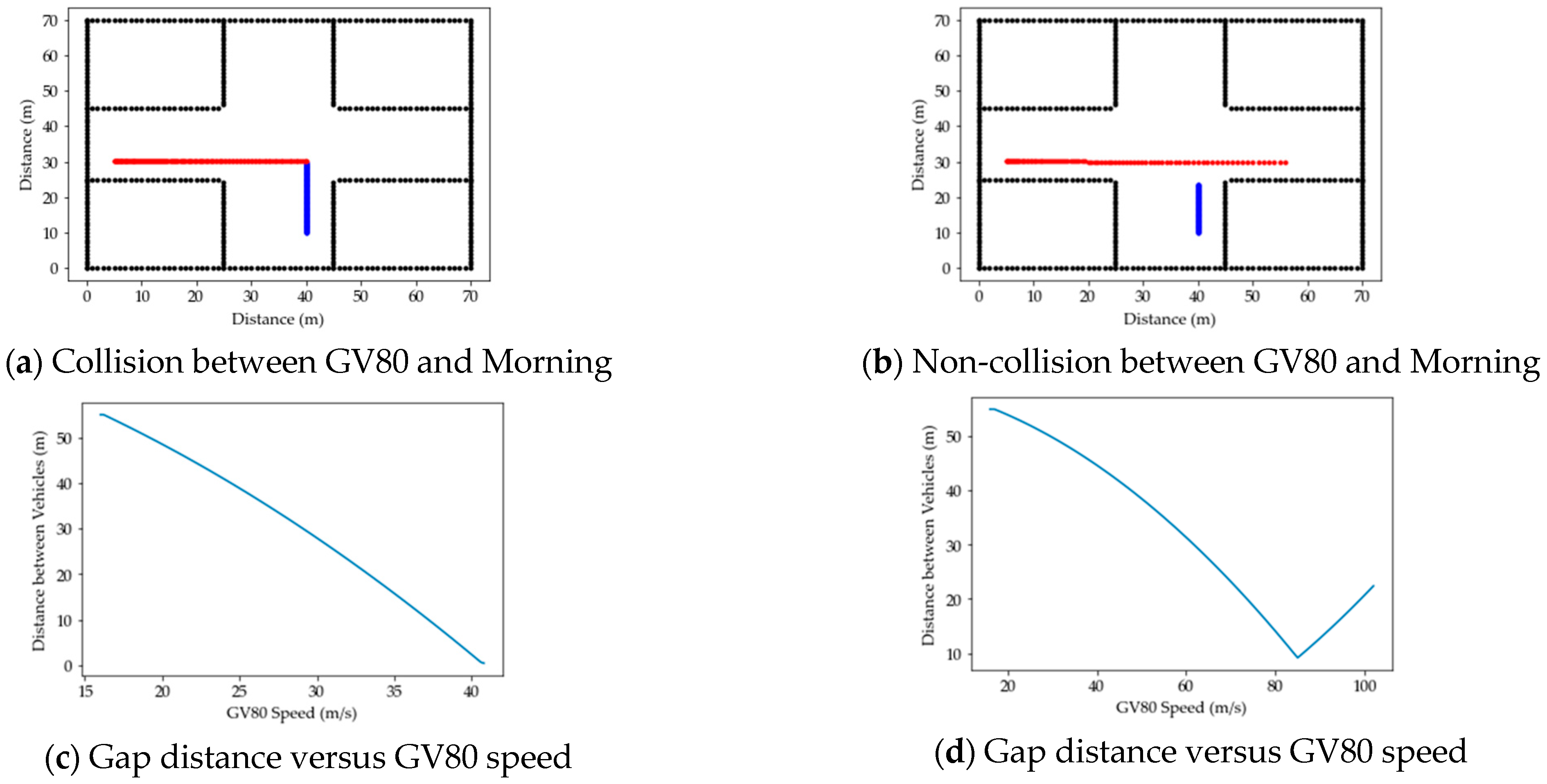
  • Simulation Environment 1: Both vehicles have the same speed, but they change in acceleration.
In order to express the collision or non-collision of vehicles in the intersection environment of Figure 6, we set the same speed while changing the acceleration. Their speed was 60 km/h (0.16 m/s), the GV80’s acceleration was 0.002 m/s, and the Morning’s acceleration was 0.16 m/s.
Figure 7 shows the collision and non-collision results by changing the acceleration according to the same speed of the two vehicles. When two vehicles collide (Figure 7a), the distance between the two vehicles gradually decreases and reaches 0 m (Figure 7c), as shown in Table 5. On the other hand, when the vehicles do not collide (Figure 7b), the distance gradually decreases and then increases again. That is, the collision and non-collision of the vehicles at the intersection is affected by their speed according to their distance. Thus, our simulator can predict an accident in advance by measuring the speed between the vehicles according to the remaining distance of entering the intersection.
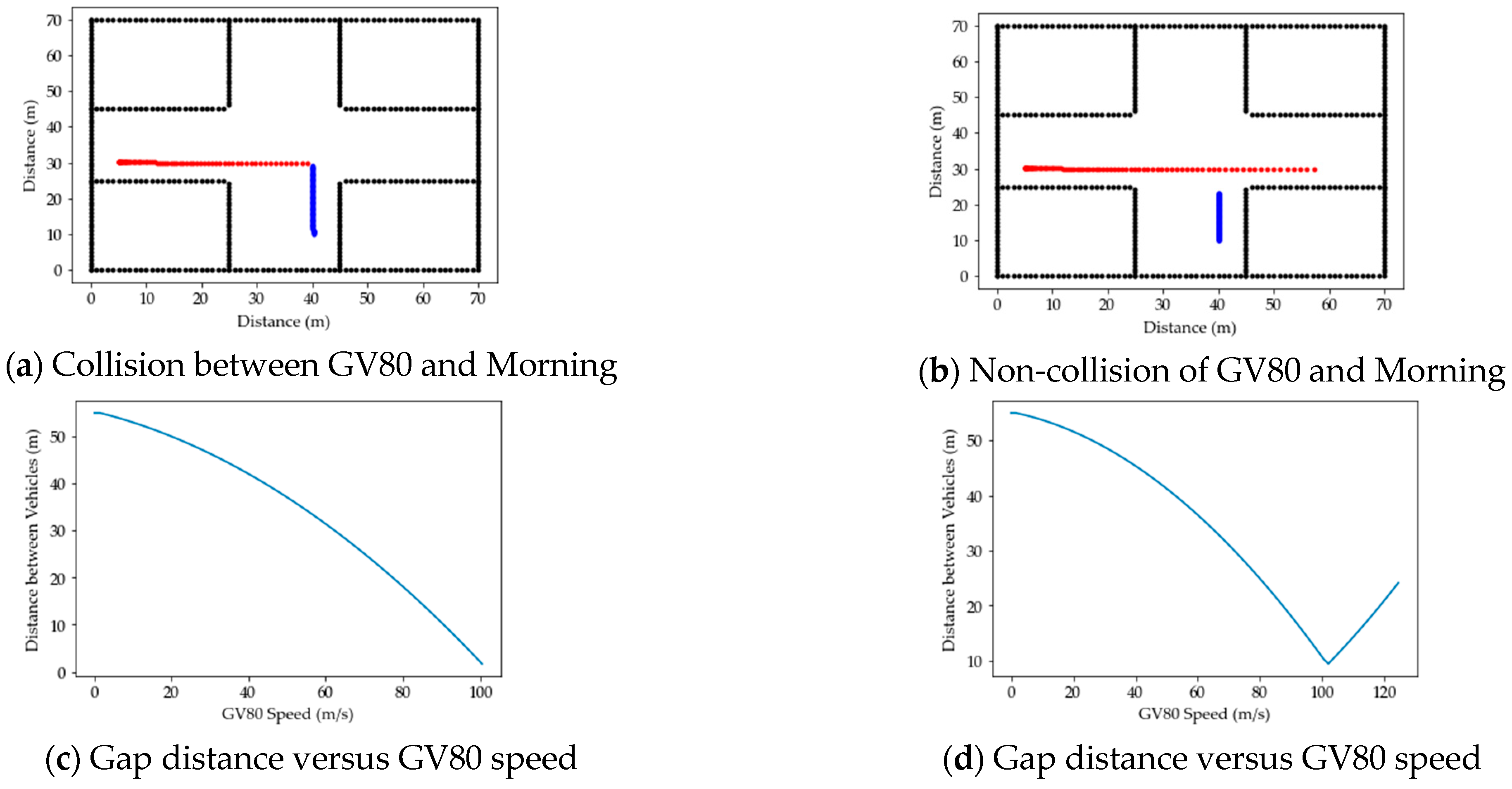
  • Simulation Environment 2: The GV80 starts slowly after stopping, and the Morning runs at a constant speed.
To express the collision or non-collision of vehicles in the intersection environment, the GV80 started after stopping, and the acceleration was 0.015. In the Morning, the speed in the event of a collision was 105 km/h, and the speed in the case of a non-collision was 80 km/h.
Figure 8 demonstrates the collision and non-collision results according to different speed changes of the two vehicles. When the vehicles collide (Figure 8a), the speed of the GV80 reaches 100 km/h (Figure 8c), as shown in Table 6. When the vehicles do not collide (Figure 8b), the speed of the GV80 reaches up to 120 km/h, while the distance narrows and then increases. Therefore, our proposed simulator simulates collision and non-collision events according to the change of distance and speed between two vehicles at the intersection.

6. Conclusions

A computer simulation is software that overcomes the limitations of time and cost and can operate under various situational conditions. Various vehicle simulators are being developed for a wide range of purposes, such as accident collision, tests of self-driving vehicles, and environment collection. Although the existing vehicle simulators (e.g., LG AD Simulator, NVIDIA Drive Sim) are able to precisely observe movement on the basis of 3D graphics, they only focus on one vehicle for driving tests. Thus, it is difficult to represent collision between vehicles in various environments. Our proposed simulator mutually complements the simulation and animation components to represent a vehicle crash. The proposed simulator synthesizes the vehicle model and road map model saved in the model repository and simulates the synthesized model using the Simpy engine in the simulation component.
Our proposed simulator has the two following contributions:
  • Simpy-based simulation for simulating the collision,
  • Unity-based animation for representing the collision using the results.
Therefore, our proposed simulator mutually complements the two components for effectively providing vehicle crash data. In future work, we will study simulators by applying vehicles and experimental parameters. We will also research the automatic generation of environments for 3D animation.

Author Contributions

Software, J.P.; Validation, H.-J.K.; Data curation, Y.L.; Writing—original draft, S.M.N.; Writing—review & editing, C.S.; Project administration, H.-J.K. All authors have read and agreed to the published version of the manuscript.

Funding

This research was partially supported by the Basic Science Research Program through the National Research Foundation of Korea (NRF) funded by the Ministry of Science and ICT (NRF-2021R1F1A1055522).

Conflicts of Interest

The authors declare no conflict of interest.

References

  1. Ibrahim, M.; Rassõlkin, A.; Vaimann, T.; Kallaste, A. Overview on digital twin for autonomous electrical vehicles propulsion drive system. Sustainability 2022, 14, 601. [Google Scholar] [CrossRef]
  2. Yu, Z.; Khan, S.A.R.; Umar, M. Circular economy practices and industry 4.0 technologies: A strategic move of automobile industry. Bus. Strategy Environ. 2022, 31, 796–809. [Google Scholar] [CrossRef]
  3. Zhou, S.; Wang, J.; Xu, B. Innovative coupling and coordination: Automobile and digital industries. Technol. Forecast. Soc. Change 2022, 176, 121497. [Google Scholar] [CrossRef]
  4. Knight, M.R.; Bernard, J. Simulation of Vehicle Collisions in Real Time; Citeseer: University Park, PA, USA, 2002. [Google Scholar]
  5. Kutela, B.; Das, S.; Dadashova, B. Mining patterns of autonomous vehicle crashes involving vulnerable road users to understand the associated factors. Accid. Anal. Prev. 2022, 165, 106473. [Google Scholar] [CrossRef] [PubMed]
  6. Sokhan-Sanj, S.; Mackulak, G.T. The value of simulation animation: Discussion of instances where statistical output is insufficient for analysis of system performance. In Proceedings of the 2nd Annual International Conference on Industrial Engineering Applications and Practice, San Diego, CA, USA, 12–15 November 1997; pp. 989–993. [Google Scholar]
  7. Nevins, M.R.; Macal, C.M.; Love, R.J.; Bragen, M.J. Simulation, animation and visualization of seaport operations. Simulation 1998, 71, 96–106. [Google Scholar] [CrossRef]
  8. Korkut, E.H.; Surer, E. Visualization in virtual reality: A systematic review. Virtual Real. 2023, 27, 1447–1480. [Google Scholar] [CrossRef]
  9. Lasseter, J. Principles of traditional animation applied to 3D computer animation. In Proceedings of the 14th Annual Conference on Computer Graphics and Interactive Techniques, Anaheim, CA, USA, 27–31 July 1987; pp. 35–44. [Google Scholar]
  10. Kerlow, I.V. The Art of 3D Computer Animation and Effects; John Wiley & Sons: Hoboken, NJ, USA, 2009. [Google Scholar]
  11. Parent, R. Computer Animation: Algorithms and Techniques; Newnes: Oxford, UK, 2012. [Google Scholar]
  12. LG_Business_Solutions. Autonomous Driving Simulator. Available online: https://www.svlsimulator.com/ (accessed on 1 June 2023).
  13. NVIDIA_DRIVE_Sim. NVIDIA DRIVE Constellation. Available online: https://developer.nvidia.com/drive/drive-constellation (accessed on 1 June 2023).
  14. Morai. Autonomous Vehicle Driving Simulator. Available online: https://ko.morai.ai/ (accessed on 1 June 2023).
  15. Shah, S.; Dey, D.; Lovett, C.; Kapoor, A. Airsim: High-fidelity visual and physical simulation for autonomous vehicles. In Field and Service Robotics: Results of the 11th International Conference; Springer: Berlin/Heidelberg, Germany, 2018; pp. 621–635. [Google Scholar]
  16. Benekohal, R.F.; Treiterer, J. CARSIM: Car-following model for simulation of traffic in normal and stop-and-go conditions. Transp. Res. Rec. 1988, 1194, 99–111. [Google Scholar]
  17. Matloff, N. Introduction to Discrete-Event Simulation and the Simpy Language; Department of Computer Science, University of California at Davis: Davis, CA, USA, 2008; pp. 1–33. [Google Scholar]
  18. Almeida, B.; Mordido, A.; Thiemann, P.; Vasconcelos, V.T. Polymorphic lambda calculus with context-free session types. Inf. Comput. 2022, 289, 104948. [Google Scholar] [CrossRef]
  19. Bierman, G.M. Operational properties of Lily, a polymorphic linear lambda calculus with recursion. Electron. Notes Theor. Comput. Sci. 2000, 41, 9. [Google Scholar] [CrossRef]
  20. Games, E. Unreal Engine. Available online: https://www.unrealengine.com/ (accessed on 1 June 2023).
  21. PX4. PX4 Autopilot. Available online: https://px4.io/ (accessed on 1 June 2023).
  22. AMERICA, H.M. 2021 GENESIS GV80. Available online: https://www.genesis.com/us/en/2021/genesis-gv80.html (accessed on 1 June 2023).
  23. Research and Business Development Foundation. Development of Experimental Platform for Safe and Fast Verification to Avoid Secondary Collisions Vehicle Safety in Multiple Vehicle; Construction & Transportation Technology Advancement R&D Report, 2018-09-03; Ministry of Land, Infrastructure and Transport: Washington, DC, USA, 2018.
  24. Hill, D.R. Object-Oriented Analysis and Simulation; Addison-Wesley: Boston, TX, USA, 1996. [Google Scholar]
  25. Baltes, S.; Ralph, P. Sampling in software engineering research: A critical review and guidelines. Empir. Softw. Eng. 2022, 27, 94. [Google Scholar] [CrossRef]
  26. Gajananan, K.; Nantes, A.; Miska, M.; Nakasone, A.; Prendinger, H. An experimental space for conducting controlled driving behavior studies based on a multiuser networked 3D virtual environment and the scenario markup language. IEEE Trans. Hum. Mach. Syst. 2013, 43, 345–358. [Google Scholar] [CrossRef]
  27. Turner, C.J.; Hutabarat, W.; Oyekan, J.; Tiwari, A. Discrete event simulation and virtual reality use in industry: New opportunities and future trends. IEEE Trans. Hum. Mach. Syst. 2016, 46, 882–894. [Google Scholar] [CrossRef]
  28. Prendinger, H.; Jain, R.; Imbert, T.; Oliveira, J.; Li, R.; Madruga, M. Evaluation of 2D and 3D interest management techniques in the distributed virtual environment DiVE. Virtual Real. 2018, 22, 263–280. [Google Scholar] [CrossRef]
Figure 1. Overview.
Figure 1. Overview.
Vehicles 05 00057 g001
Figure 2. Vehicle collision points.
Vehicles 05 00057 g002
Figure 3. Map translator.
Vehicles 05 00057 g003
Figure 4. Execution flowchart of the simulation component.
Vehicles 05 00057 g004
Figure 5. Animation component’s procedures.
Vehicles 05 00057 g005
Figure 6. Experiment environment of an intersection.
Vehicles 05 00057 g006
Figure 7. Simulation results of Environment 1.
Vehicles 05 00057 g007
Figure 8. Simulation results of Environment 2.
Vehicles 05 00057 g008
Table 1. Comparison of typical existing vehicle simulators.
TypeLG AD
Simulator
NVIDIA Drive SimMorai SimulatorMicrosoft
AirSim
Carsim
FeatureAutonomous drivingMulti-sensor based self-driving virtual testbedSimulation of a realistic vehicle driving environmentData generation related to autonomous vehiclesAccurate, detailed, efficient methods for simulating vehicles
Open SourceYesNoNoYesNo
3D MapSupportSupportSupportSupportSupport
HILSupportSupportUnidentifiedSupportUnidentified
SILSupportSupportUnidentifiedSupportUnidentified
VILSupportUnidentifiedSupportUnidentifiedUnidentified
CountryRepublic of KoreaUSARepublic of KoreaUSAUSA
Table 2. CheckCollision function.
1:
def checkCollision(pos_1st, pos_2nd)
2:
  rslt = FALSE
3:
  distance = calculateDistance(pos_1st, pos_2nd)
4:
 
5:
  if distance <= 1 then
6:
    rslt = TRUE
7:
  end if
8:
result rslt
Table 3. CrashPoint Function.
1:
def crashPoint(vehicle_1st, vehicle_2nd, pos_1st, pos_2nd, angle_1st, angle_2nd)
2:
 collision_side = NULL
3:
 
4:
  if angle_1st = angle_2nd then
5:
    rslt = collison_BACK
6:
  else if abs(angle_1st - angle_2nd) = 180 then
7:
    rslt = collsion_FRONT
8:
  else if 0 < angle_1st < 180 then
9:
    if angle_1st - angle_2nd < −180 then
10:
     collision_side = RIGHT_SIDE
11:
   else if angle_1st - angle_2nd < 0 then
12:
     collision_side = LEFT_SIDE
13:
   else if angle_1st - angle_2nd < 180 then
14:
     collision_side = RIGHT_SIDE
15:
  else
16:
   if angle_1st - angle_2nd > 180 then
17:
      collision_side = LEFT_SIDE
18:
   else if angle_1st - angle_2nd > 0 then
19:
      collision_side = RIGHT_SIDE
20:
   else if angle_1st - angle_2nd > −180 then
21:
      collision_side = LEFT_SIDE
22:
  end if
23:
 
24:
  if collision_side = RIGHT_SIDE or LEFT_SIDE then
25:
   distance = calculateDistance(pos_1st, pos_2nd)
26:
   if distance < vehicle_1st.length/100/3 then
27:
      rslt = collision_RIGHT_TOP_SIDE
28:
   else if distance < vehicle1.length/100/3 * 2 then
29:
      rslt = collision_RIGHT_SIDE
30:
   else if distance < vehicle1.length/100 then
31:
      rslt = collision_RIGHT_BOTTOM_SIDE
32:
   end if
33:
  end if
34:
return rslt
Table 4. Parameters of the Genesis GV80 and the KIA Morning.
ParametersGenesis GV80KIA Morning
Empty Wight2100 kg910 kg
Length4945 mm3595 mm
Width1975 mm1595 mm
Engine2.5 Gasoline Turbo1.0 Gasoline
Tire22 inches14 inches
Table 5. Collision between GV80 and Morning.
VehicleType
(m/s)
Result Order
12345
GV80Speed0.160.160.160.160.16
Acceleration00.010.0010.0020
MorningSpeed0.160.160.160.160.16
Acceleration00000.01
Collision statusFalseFalseFalseTrueFalse
Table 6. Collision between GV80 and Morning.
VehicleType
(m/s)
Result Order
12345
GV80Speed0.160.220.160.220.16
Acceleration00000
MorningSpeed0.160.160.110.110
Acceleration0.0010.0010.0010.0010.008
Collision statusFalseFalseFalseFalseTrue
Disclaimer/Publisher’s Note: The statements, opinions and data contained in all publications are solely those of the individual author(s) and contributor(s) and not of MDPI and/or the editor(s). MDPI and/or the editor(s) disclaim responsibility for any injury to people or property resulting from any ideas, methods, instructions or products referred to in the content.

