Article

Stick–Slip Characteristic Analysis of High-Speed Train Brake Systems: A Disc–Block Friction System with Different Friction Radii

1
School of Mechanical Engineering, Southwest Jiaotong University, Chengdu 610031, China
2
State Key Laboratory of Traction Power, Southwest Jiaotong University, Chengdu 610031, China
3
CRRC Qishuyan Institute Co., Ltd., Changzhou 213011, China
*
Author to whom correspondence should be addressed.
Vehicles 2023, 5(1), 41-54; https://doi.org/10.3390/vehicles5010003
Submission received: 31 October 2022 / Revised: 22 December 2022 / Accepted: 23 December 2022 / Published: 2 January 2023
(This article belongs to the Special Issue Rotordynamics in Automotive Engineering)

Abstract

:
Inspired by the difference in the friction radii of the pads from the high-speed train brake system, stick–slip experiments for a disc–block friction system with different friction radii were carried out via a test device. Based on the test results, the stick–slip vibration characteristics of the disc–block friction system with variation in the friction radius were analyzed, and the corresponding Stribeck model parameters in exponential and fractional forms were identified. The experimental results show that with an increase in the friction radius the vibration amplitude first increased and then decreased and the frequency of stick–slip vibration increased. The identified Stribeck model parameters show that the decay factors increased, the static friction coefficient decreased, and the dynamic friction coefficient decreased first and then increased as the friction radius increased. Moreover, the identified Stribeck model in an exponential form can more accurately reflect the stick–slip characteristics of a disc–block friction system than the model in a fractional form. It can be further applied in the investigation of the dynamic behaviors of high-speed train brake systems.

1. Introduction

High-speed trains play an important role in transportation and the development of the national economy. With the continuous increase in the operating speed and the complexity of the operating environment, the status of the brake system in safe operation is becoming more prominent. The disc brake system is widely adopted in high-speed trains to ensure safe operation. Braking is realized by disc–block friction to consume the kinetic energy of the train. However, this friction mode may cause unstable vibration [1,2,3,4,5], which disables the brake calipers [6,7], damages the brake disc structure [8,9,10], and reduces the service life of the brake pad [11,12,13]. It will even lead to abnormal noise [14,15,16], which significantly affects the comfort of passengers and residents near the railway line. Therefore, it is urgent to investigate the mechanism of friction-induced vibration of high-speed train disc brake systems.
Modal coupling is when two close modes of the friction system gradually integrate into a single complex mode with an increase in the friction coefficient [17]. Brake squeal caused by modal coupling instability usually occurs at high speeds. Many studies have been conducted to seek effective methods to suppress friction-induced vibration and brake squeal by taking friction blocks as the object. Methods mainly include punching, changing the shape, adjusting the installation angle, adding damping components, replacing materials, grooving and chamfering, etc. Tang et al. [18] studied the effects of friction blocks with and without holes on braking performance and noise. The results showed that the blocks with holes could better capture the wear debris and reduced brake noise compared with the blocks without perforations. Xiang et al. [19] studied the effect of friction block shape on the tribological and dynamic behavior of a high-speed train brake system. The results showed that the contact pressure distribution of the hexagonal friction pad was more uniform, resulting in the lowest contact stiffness, wear, vibration, and noise. Tang et al. [20] further conducted vibration and noise experiments by adopting friction blocks with different shapes, and the results showed that the triangular block had the highest sound pressure level. Quan et al. [21] performed friction experiments to explore the tribological behaviors of brake pads with different installation angles. The results showed that the difference in installation angle affected the behavior of wear debris, the distribution of contact pressure, and the contact state of the friction interface, thereby affecting the noise performance. Wu et al. [22] added different damping components to the brake block, which improved the interface contact state and reduced the friction noise. EL-Tayeb et al. [23] developed new friction brake pad materials and studied the effects of material properties on the friction coefficient. The results showed that wear rates were substantially dependent on the type or ingredient of brake pad materials and the pressure. Li [24] and Abdo [25] performed chamfering and grooving on the surface of a brake pad, and the results showed that the depth of the groove and the size of the chamfer had noticeable impacts on the modal characteristics of the brake pad structure, indicating that the groove or chamfer of the brake pad had great potential in suppressing braking noise.
These research achievements have great significance for improving brake performance, reducing friction vibration, and suppressing squeal at high speeds. However, the friction self-excited vibration also becomes prominent at low speeds. Therefore, it is particularly important to explore the vibration characteristics of the friction brake system at low speeds. Usually, the unstable vibration when braking at low speeds is stick–slip vibration [26,27]. Stick–slip vibration is a phenomenon of ‘relative motion—static—re motion—re static’ between friction pairs caused by the different values of the dynamic and static friction coefficients [28]. Research shows that the stick–slip vibration is caused by the negative slope characteristic of the friction coefficient [29,30]. The stick–slip vibration behavior of the brake system is affected by the system parameters, brake conditions, friction interface characteristics, and other factors. Huang et al. [31] carried out a stick–slip vibration test based on disc and friction block samples processed from an automotive brake system. The results showed that the normal force and rotational speed affected the stick–slip vibration characteristics of the friction system. Abdo et al. [32] studied the relationship among the stick–slip vibration amplitude, vibration frequency, and relative humidity. The results showed that the reduction rate of the stick–slip amplitude was closely related to the vibration frequency and relative humidity. Wang et al. [33] studied the stick–slip behaviors of an automotive disc brake system in ABAQUS. The results showed that an increase in braking load increased the tangential displacement of the brake pads, reduced the period of stick–slip vibration, and caused a more obvious brake chatter phenomenon. Wang et al. [34] studied the influence of alternating positive pressure on stick–slip vibration characteristics. The results showed that increasing the circular frequency would stimulate a higher response frequency from the system energy, which was close to a certain natural frequency of the friction system. Meng et al. [35] proposed a new model to quantify the stick–slip groaning of an automotive brake system. The results showed that the vibration shock of the pad-disc system was triggered by stick–slip vibration and was closely related to the wide-band instability and pulsed stick–slip vibration. Wang et al. [36] analyzed the dynamic behaviors of a high-speed train disc brake system through numerical simulation. The results showed that with an increase in the normal braking force, the disc–block brake system alternately presented periodic and chaotic stick–slip motions.
At present, most of the stick–slip vibration studies have been based on finite element and numerical simulations. Due to the complexity and randomness of stick–slip vibration, the disc–block interface characteristics have not been fully considered in the simulation analyses.
Hence, experimental investigation is another effective method to reveal the key influencing factors of stick–slip vibration. In addition, the distance between the friction block and the rotational center of the brake disc, defined as the friction radius, is different (as shown in Figure 1), which may affect the stick–slip characteristics of a brake system. Therefore, in this paper, experiments were carried out to study stick–slip vibration characteristics under different friction radii, adopting a block-on-disc configuration processed from high-speed train brake materials. Then, the Stribeck model was selected, and the corresponding parameters were identified to intuitively characterize the stick–slip property. The result can provide a reference for understanding the dynamic characteristics of the train braking friction block at different friction radii.

2. Experimental Process

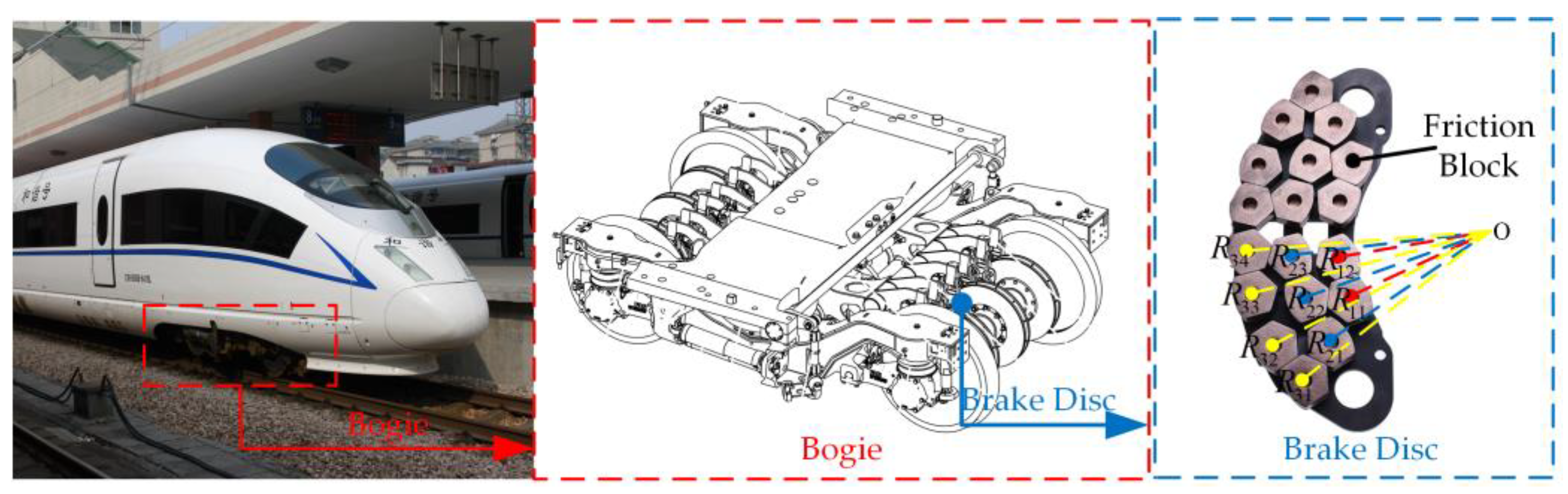
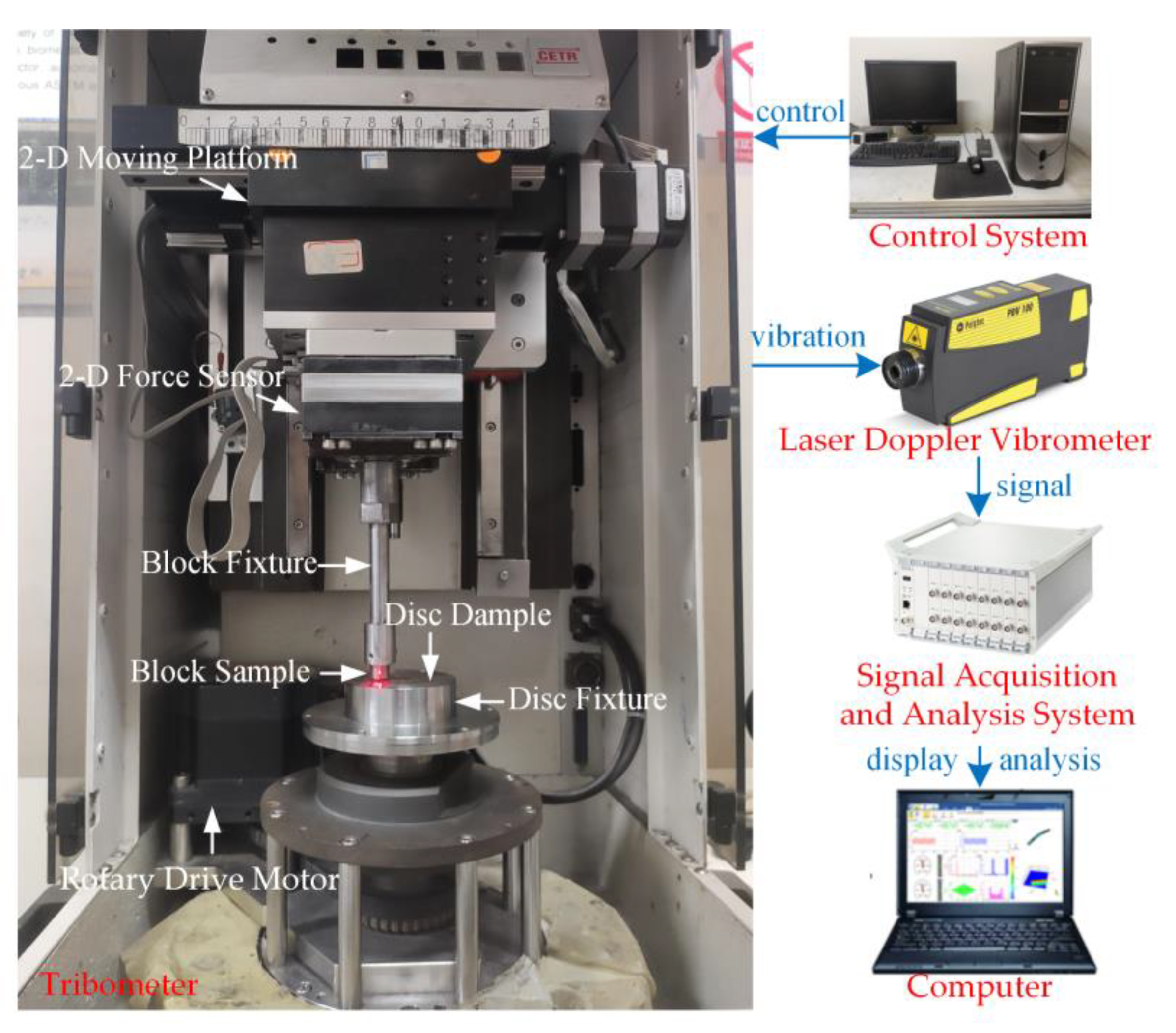
2.1. Experimental Device

The experimental device mainly included a friction test system and a signal acquisition and analysis system, as shown in Figure 2. The friction test system consisted of a small-scale tribometer (CETR UMT-3) and a computer controller. The tribometer was mainly composed of a two-dimensional force sensor, a two-dimensional moving platform, two sample fixtures, and a rotary drive motor. The two-dimensional force sensor was integrated with the two-dimensional moving platform, and it was used to measure the normal force and tangential force of the disc–block friction interface. The upper end of the block fixture was bolted to the two-dimensional force sensor. The lower end of the block fixture fixed the friction block with bolts. The disc fixture was bolted to the rotary drive motor output device.
The control system was used to control the rotational speed of the rotary drive motor, the normal force between the friction contact interface, and the size of the friction radius. The signal acquisition and analysis system mainly included a laser doppler vibrometer (Polytec PDV-100), a data acquisition instrument (DH5922N), and a computer that was adapted for display and analysis. The laser doppler vibrometer was used to measure the tangential velocity of the friction block, and its frequency response range was 0.5 Hz–22 kHz. The data acquisition instrument was used to acquire the signal, and the sampling frequency of the signal was set to 20 kHz.

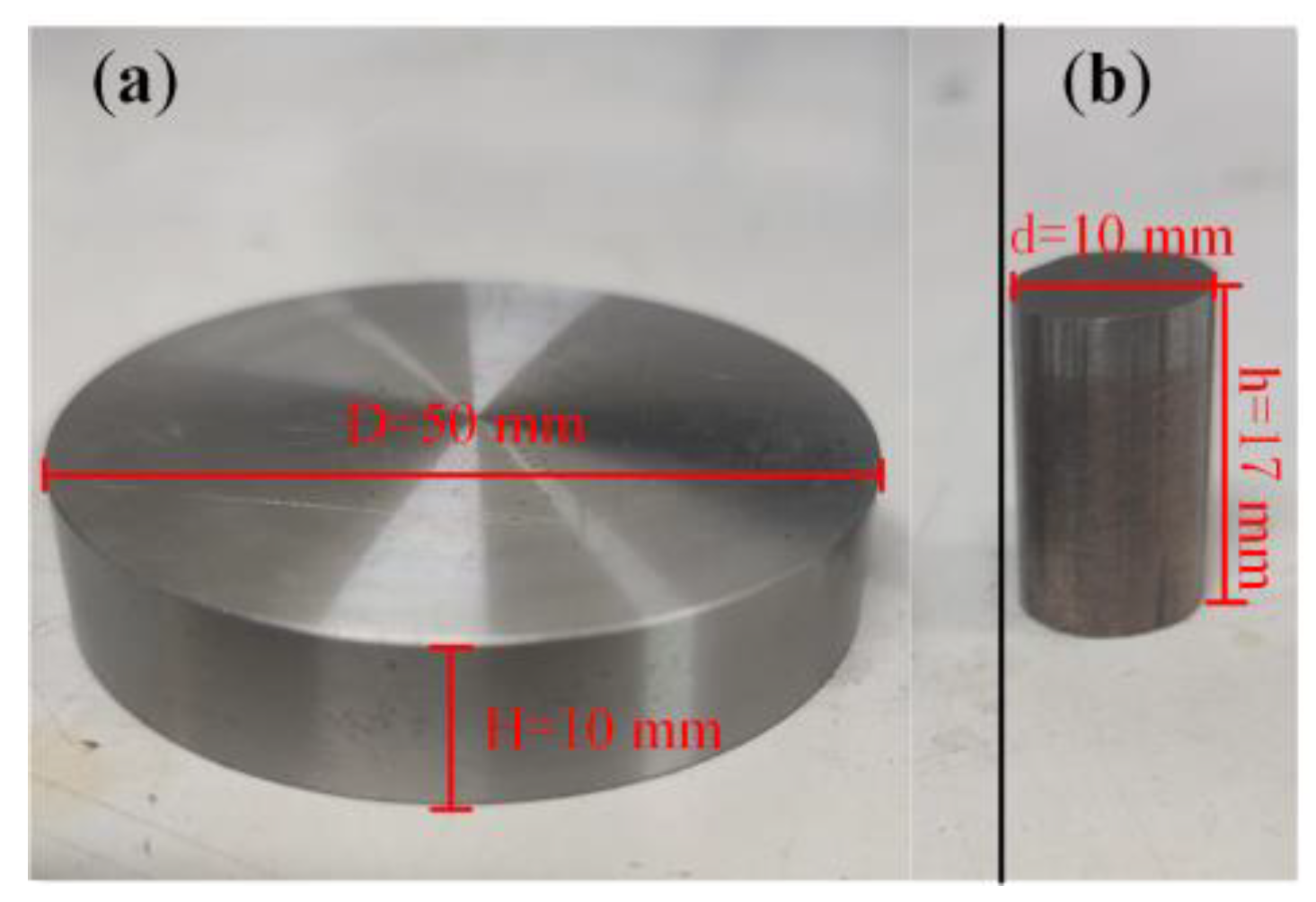
2.2. Experimental Samples

The experimental samples are shown in Figure 3. The disc test sample had a diameter of 50 mm and a thickness of 10 mm. Its material was the same as that of the brake disc for a high-speed train brake system. The chemical composition of the disc test sample is shown in Table 1. The cross-section of the brake pads commonly used in the high-speed train brake system had three shapes: circle, pentagon, and hexagon. Considering that the leading edges of the pentagon and hexagon noticeably affect the system vibration [19], the circle was selected as the cross-sectional shape of the friction block sample in the experiment. The friction block was cut from a brake pad of a high-speed train brake system whose diameter was 10 mm and height was 17 mm. The chemical composition of the block test sample is shown in Table 2. The material properties of the disc and block test samples are shown in Table 3.

2.3. Experimental Step
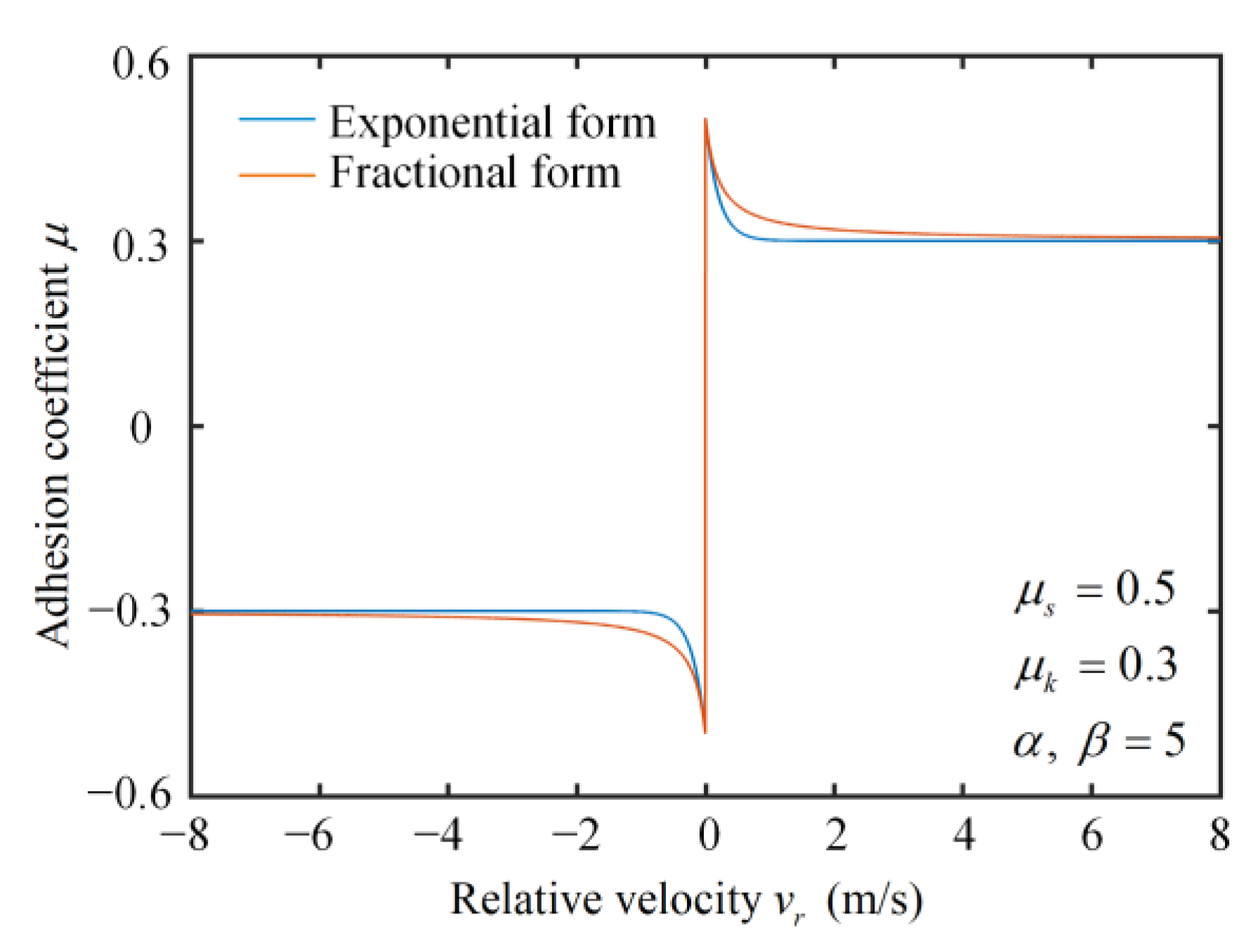
In order to identify the Stribeck model parameters and study stick–slip vibration characteristics under different friction radii at a low speed, four group experiments with different friction radii were carried out in which the friction radii were selected as 9 mm, 12 mm, 15 mm, and 18 mm.
In order to equalize the pressure between the friction block and the brake disc under the normal braking force ( F 0 = 18   kN ), the normal force ( F 1 ) between the disc sample and the block sample was scaled in the test according to Equation (1), where n is the number of friction blocks on the brake pad; S b 0 is the cross-sectional area of the original friction block; and S b 1 is the cross-sectional area of the friction block sample. The calculation result was about 50 N. Therefore, it was set to 50 N in the experiment. Stick–slip vibration usually occurs under low-speed braking. After several low-speed braking tests, it was found that there was an obvious stick–slip vibration when the rotational speed was set to 4 rpm. Therefore, the rotational speed was set to 4 rpm in the test.
F 1 = F 0 S b 1 n S b 0
Before the experiment, the friction radius was set to a preset value by adjusting the two-dimensional moving platform. Then, the running-in procedure was performed to obtain good flat contact between the block and the disc. At the beginning of the experiment, the two-dimensional moving platform drove the block to move down until the normal force between the disc and the block reached the preset value. Thereafter, the motor drove the disc to rotate, and the rotational speed of the disc increased steadily from a standstill to a preset value and remained constant until the end of the experiment. In order to ensure the reliability and repeatability of the experiment, each group of experiments with different friction radii was repeated four times, and the time for each test was 2 min. All tests were guaranteed to be carried out in an environment with a humidity of 50 ± 10 % RH and a temperature of 24 27   ° C .

2.4. Stribeck Model

The Stribeck model, also known as the Stribeck effect, is mainly used to describe the friction behavior in a low-velocity range, where the coefficient of friction is defined as a function of relative velocity with a negative slope [37,38]. The expressions of the Stribeck model generally have two forms: exponential [39] and fractional types [40,41], as shown in Figure 4, and these two forms of the Stribeck model are adopted to characterize the negative friction–velocity slope of the disc–block friction system with different friction radii in experiments. The relationship between the friction coefficient and the relative velocity of the exponential-type Stribeck model is expressed as follows [39]:
μ ( v r ) = [ μ k + ( μ s μ k ) e α | v r | ] s i g n ( v r )
A fractional expression including the coefficients of dynamic and static friction was proposed in [42], and the expression of the fractional-type Stribeck model is written as follows [42]:
μ ( v r ) = [ μ k + ( μ s μ k ) 1 + β | v r | ] s i g n ( v r )
where μ s and μ k represent the static friction coefficient and the kinetic friction coefficient; α and β are the fractional decay factor and the exponential decay factor, which are used to control the degree of negative slope; and v r represents the relative speed between the disc and the block, which is calculated as follows:
v r = ω r v b
where ω is the rotational speed of the disc; r is the distance from the geometric center of the block to the rotational center of the disc; and v b is the tangential speed of the block.

3. Experimental Results and Discussion

The parameters of the Stribeck model contain the relative velocity, friction coefficient, and decay factor. Therefore, the relative velocity, which can reflect stick–slip vibration characteristics, was analyzed first. Then, the friction coefficient signal was processed to obtain the kinetic and static friction coefficients. Finally, the relationship between the relative velocity and the friction coefficient was explored, and the corresponding Stribeck model parameters were identified by the MATLAB function fitting toolbox.

3.1. Analysis of Stick–Slip Vibration

Figure 5 shows the root-mean-square values and the error bars of tangential velocity signals for the friction block in four groups of repeated tests under different friction radius conditions. Obviously, it was found that the error bars of the results under the four working conditions were all small, which indicates that the experiment had good repeatability and reliability. Thus, the experimental results could be further analyzed. Additionally, with the friction radius increases, the tangential velocity of the friction block first increased and then decreased. When the friction radius was 15 mm, the tangential velocity reached its maximum.
The rotational speed of the disc and friction radius were defined in the tests, and the tangential velocity of the block was measured by the vibrometer. Then, the disc–block relative velocity could be calculated according to Equation (4). Figure 6 shows the time-domain responses of disc–block relative velocity under four working conditions with friction radii of 9 mm, 12 mm, 15 mm, and 18 mm. Within one second, the numbers of stick–slip vibrations were 3, 4, 5, and 6, respectively, and the amplitudes of the disc–block relative velocities were 56.5 mm/s, 66.2 mm/s, 83.9 mm/s, and 72.7 mm/s, respectively. This indicates that with the increase in the friction radius, the period of stick–slip vibration decreased and the amplitude of stick–slip vibration increased first and then decreased. When the friction radius was 15 mm, the vibration intensity was the highest.
The frequency-domain responses of the disc–block relative velocity under these four friction radius conditions were further analyzed, as shown in Figure 7. The results show that the fundamental frequencies of the system were 3.662 Hz, 4.272 Hz, 4.883 Hz, and 5.493 Hz, respectively, which illustrates that the stick–slip vibration frequency increased with the increase in the friction radius. The energy amplitudes at the fundamental frequencies were 1.284, 1.526, 2.640, and 2.432, which also indicates that the intensity of stick–slip vibration increased first and then decreased with the increase in the friction radius.

3.2. Analysis of Friction Coefficient

Figure 8 shows the time-domain responses of the disc–block friction coefficient at the friction radii of (a) 9 mm, (b) 12 mm, (c) 15 mm, and (d) 18 mm. The time range is consistent with that of Figure 6. When stick–slip vibration occurred, the disc–block relative velocity was almost zero, and the friction coefficient was increased in the stick state. When the friction coefficient rose to a certain maximum value, the relative velocity was variable and the friction coefficient decreased rapidly, indicating that the system moves into the slip state. In a stick–slip vibration period, the maximum friction coefficient in the stick state is defined as the static friction coefficient, and the minimum friction coefficient in the slip state is defined as the dynamic friction coefficient. The static friction coefficients were 0.521, 0.512, 0.509, and 0.500. The dynamic friction coefficients were 0.388, 0.375, 0.318, and 0.355.
The variation trends of the dynamic and static friction coefficients at the friction radii of (a) 9 mm, (b) 12 mm, (c) 15 mm, and (d) 18 mm were further analyzed, as shown in Figure 9. The results display that with the increase in the friction radius the static friction coefficient always decreased, while the dynamic friction coefficient decreased first and then increased. The differences between the dynamic and static friction coefficients were 0.131, 0.137, 0.191, and 0.144 at the friction radii of 9 mm, 12 mm, 15 mm, and 18 mm, respectively. The amplitude of the stick–slip vibration was positively related to the difference between the dynamic and static friction coefficients. With the friction radius increases, the difference increased first and then decreased. When the friction radius was 15 mm, the difference reached its maximum. Therefore, the variation trend of the RMS of the tangential velocity in Figure 5 was consistent with that of the differences between the dynamic and static friction coefficients in Figure 9.
The velocity of the friction interface was proportional to the friction radius. With the increase in the friction radius, it is possible that the dynamic friction coefficient decreased first and then increased while the static friction coefficient decreased. Finally, at a higher velocity, there was no stick–slip. Instead, there was pure sliding, and the dynamic and static friction coefficients converged into a single friction coefficient.

3.3. Stribeck Model Parameter Identification

To explore the relationship between the disc–block relative velocity and the friction coefficient, the relative velocity was set as the horizontal coordinate, and the corresponding friction coefficient was set as the vertical coordinate. The results are shown in Figure 10 (the disc–block relative velocity is from Figure 6, and the friction coefficient is from Figure 8). Obviously, there was a negative correlation between the disc–block relative velocity and the friction coefficient, which is consistent with the Stribeck effect. Thus, the Stribeck model parameters were identified to reveal the friction characteristics of the disc–block friction system. The dynamic and static friction coefficients were obtained in Section 3.2. To acquire the exponential and fractional forms of the Stribeck model, the exponential decay factor and the fractional decay factor needed to be further determined. Taking the exponential decay factor and the fractional decay factor as unknown parameters, the exponential and fractional forms of the Stribeck model were set as the objective functions. Then, the experimental results and the two types of Stribeck models were fitted in MATLAB. The fitting curves of the exponential and fractional forms of the Stribeck model are shown in Figure 10 and Figure 11.
For the convenience of analysis, the identified Stribeck model parameters at different friction radii are listed in Table 4. It can be seen that the decay factors of the fractional and exponential Stribeck models both increased with the increment of the friction radius.
In order to compare the fitting degree between the identified Stribeck friction model and the test results, an error analysis of the fitting results under different friction radii was carried out. The expression of the relative error (e) is written as follows:
e = | μ t e s t μ f i t μ t e s t |
where μ t e s t is the friction coefficient obtained from the test and μ f i t is the friction coefficient obtained by fitting.
The error curves under different friction radii were calculated and are shown in Figure 12. The results show that the errors of the fractional and exponential Stribeck models were each less than 0.08 under the four friction radius conditions, indicating that these two forms of Stribeck models can accurately reflect the relationship between the friction coefficient and the relative velocity. Additionally, it can be observed that, although the errors of the two forms of Stribeck model were both small, the error of the fractional Stribeck model was relatively higher than that of the exponential form. Therefore, the identified exponential Stribeck friction model was more in agreement with the experimental results.
Vehicles 05 00003 g012

4. Conclusions

In this paper, the stick–slip vibration characteristics of a disc–block friction system under different friction radii were analyzed based on a CETR-UMT3 tribometer. The specific parameters of the Stribeck friction model with two different expressions were identified, and the relationship among the friction radius, stick–slip vibration, and the parameters of the Stribeck friction model was revealed. The following conclusions were drawn:
(1).
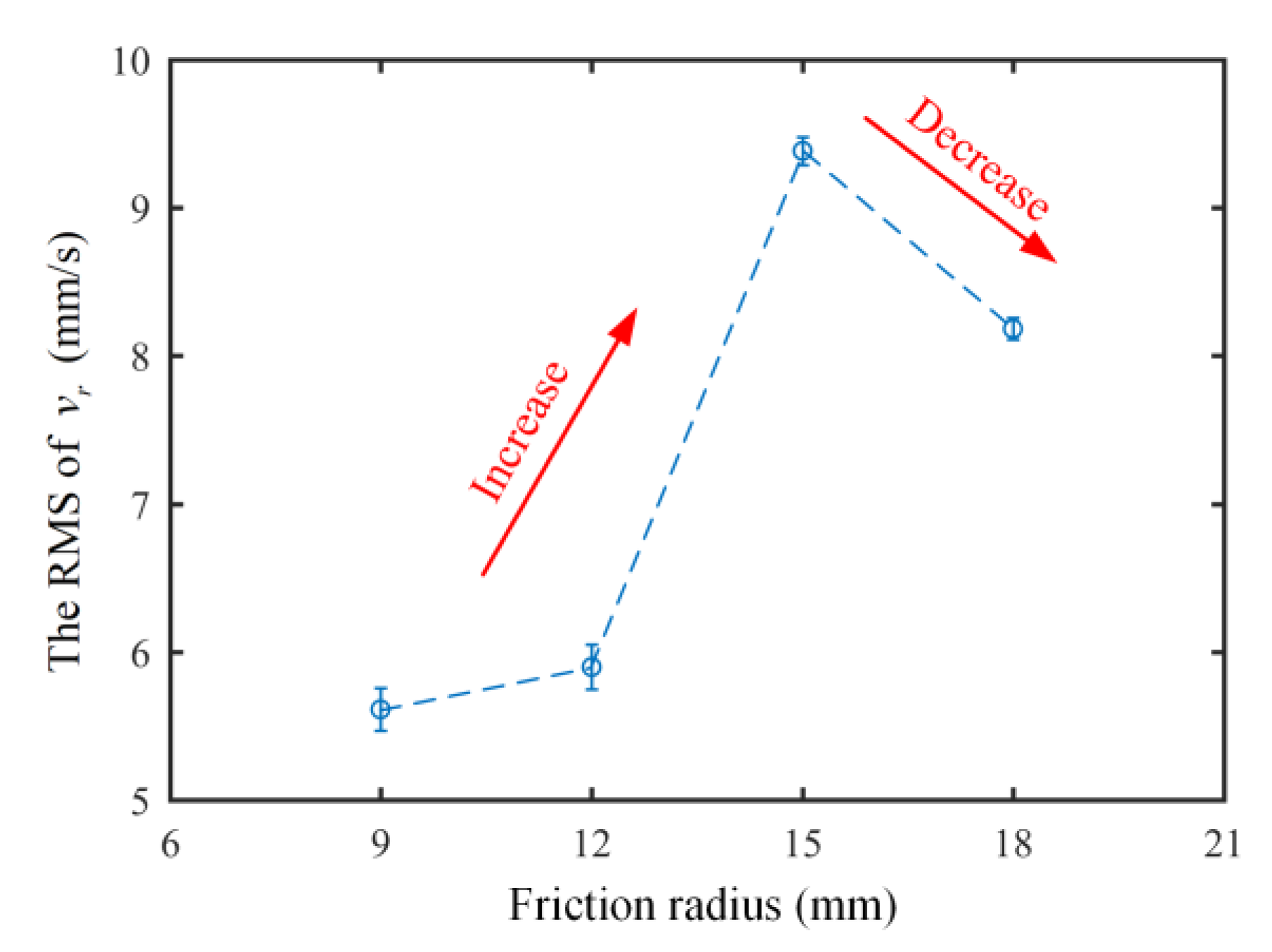
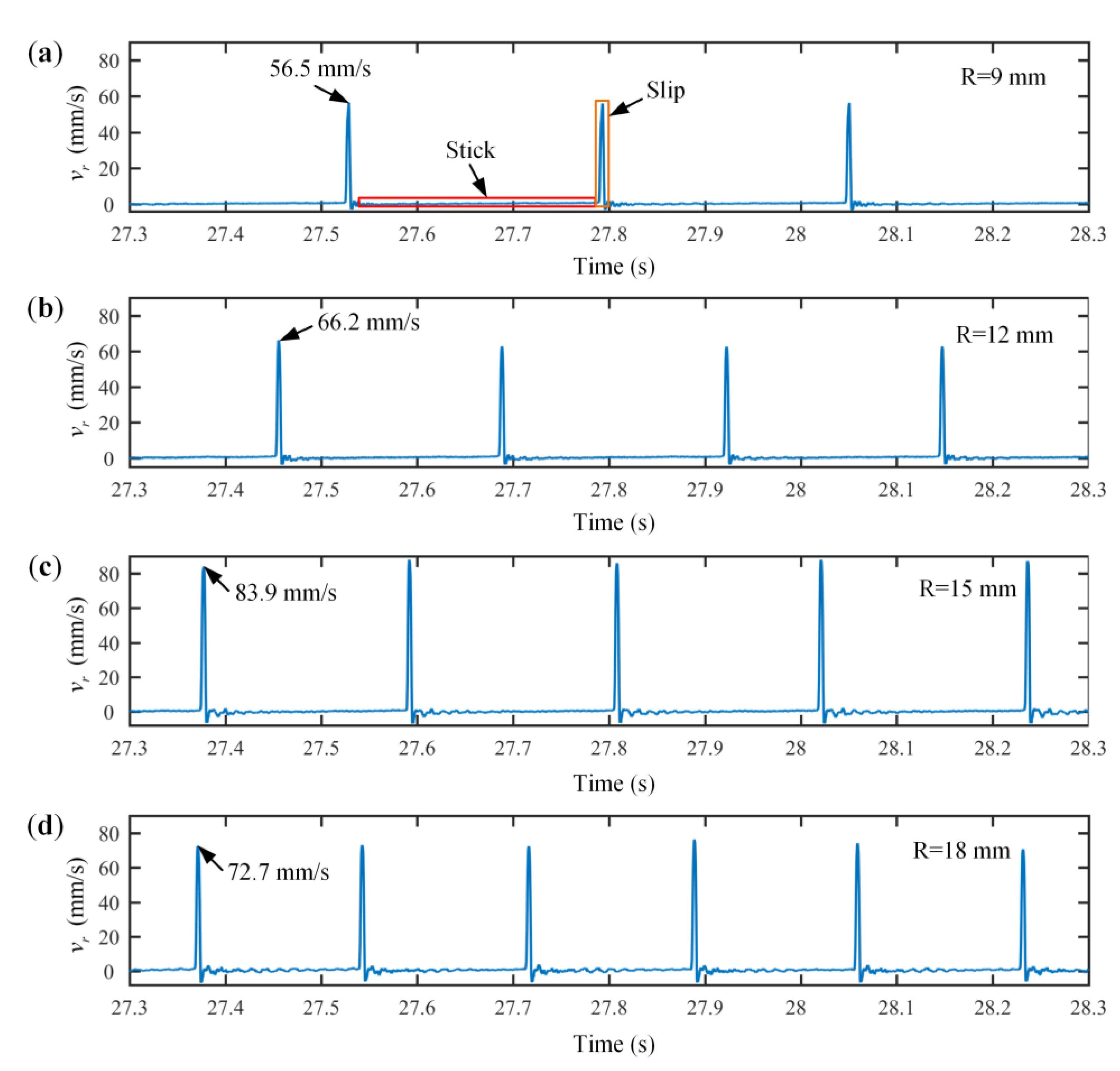
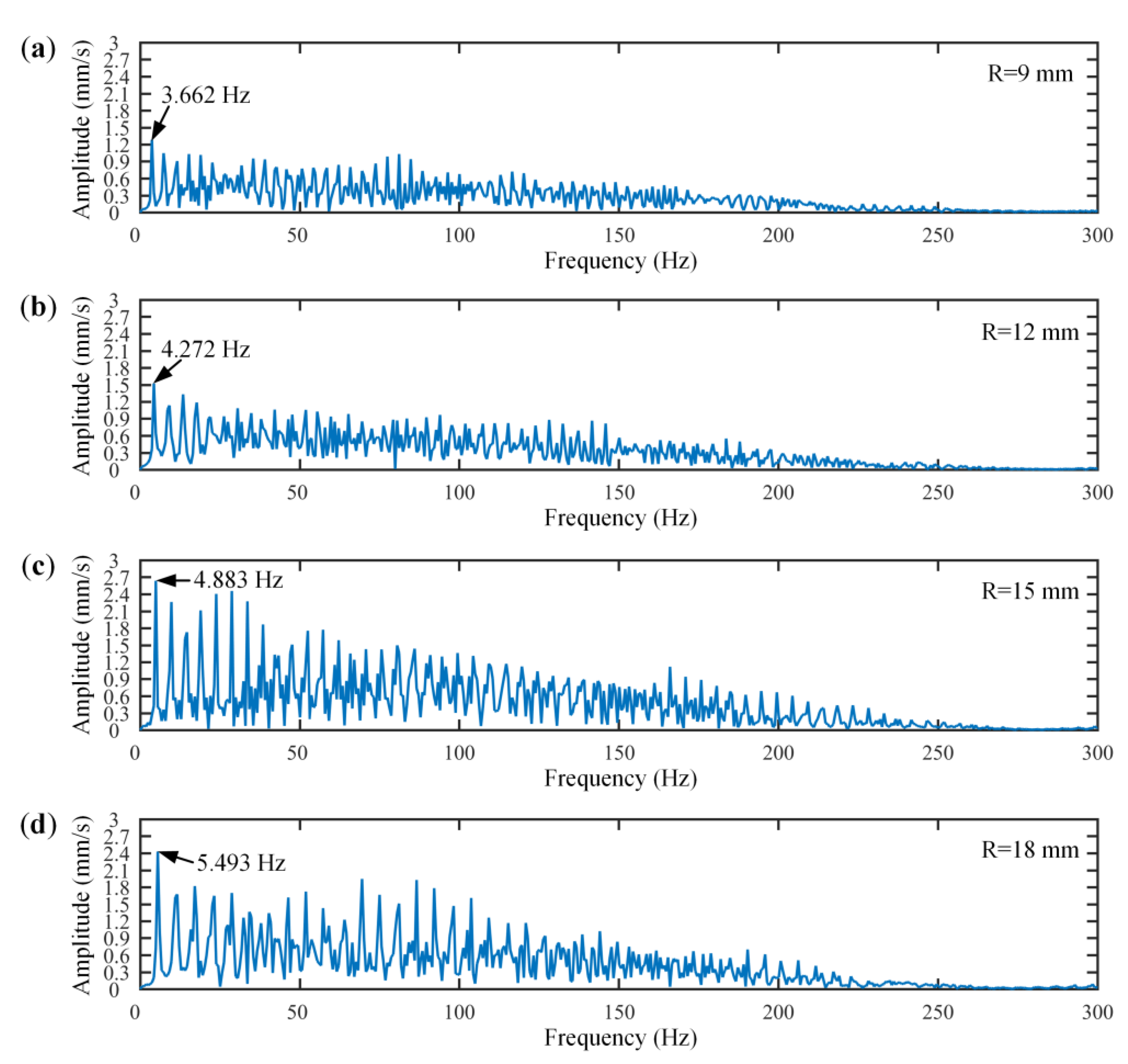
The disc–block friction systems with four different friction radii all experienced stick–slip vibration. As the friction radius increased, the period of stick–slip vibration decreased and the amplitude of stick–slip vibration first increased and then decreased. The amplitude was lowest when the friction radius was 9 mm. The fundamental frequency increased and the corresponding amplitude increased and then decreased, which was consistent with the time-domain response results.
(2).
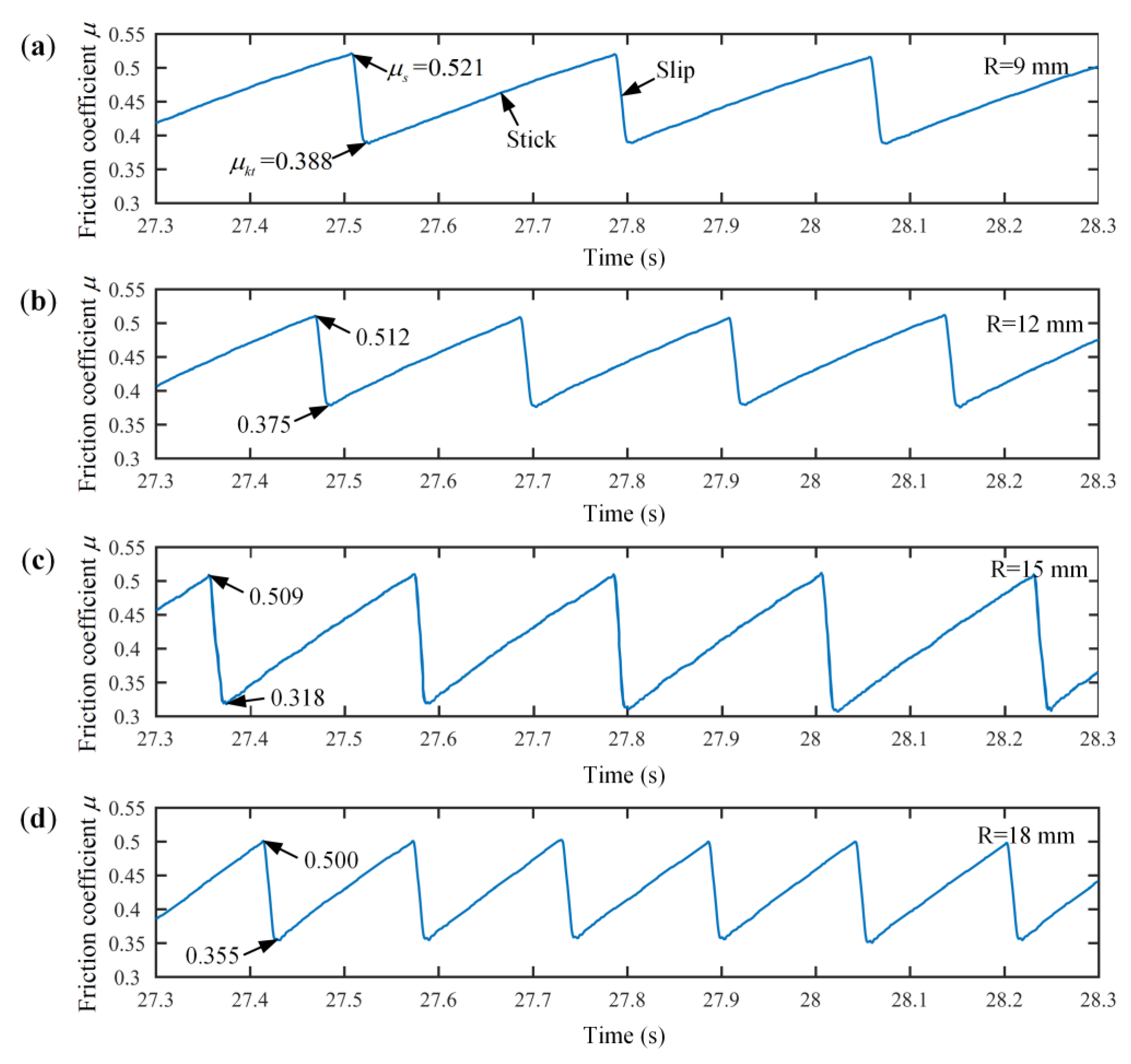
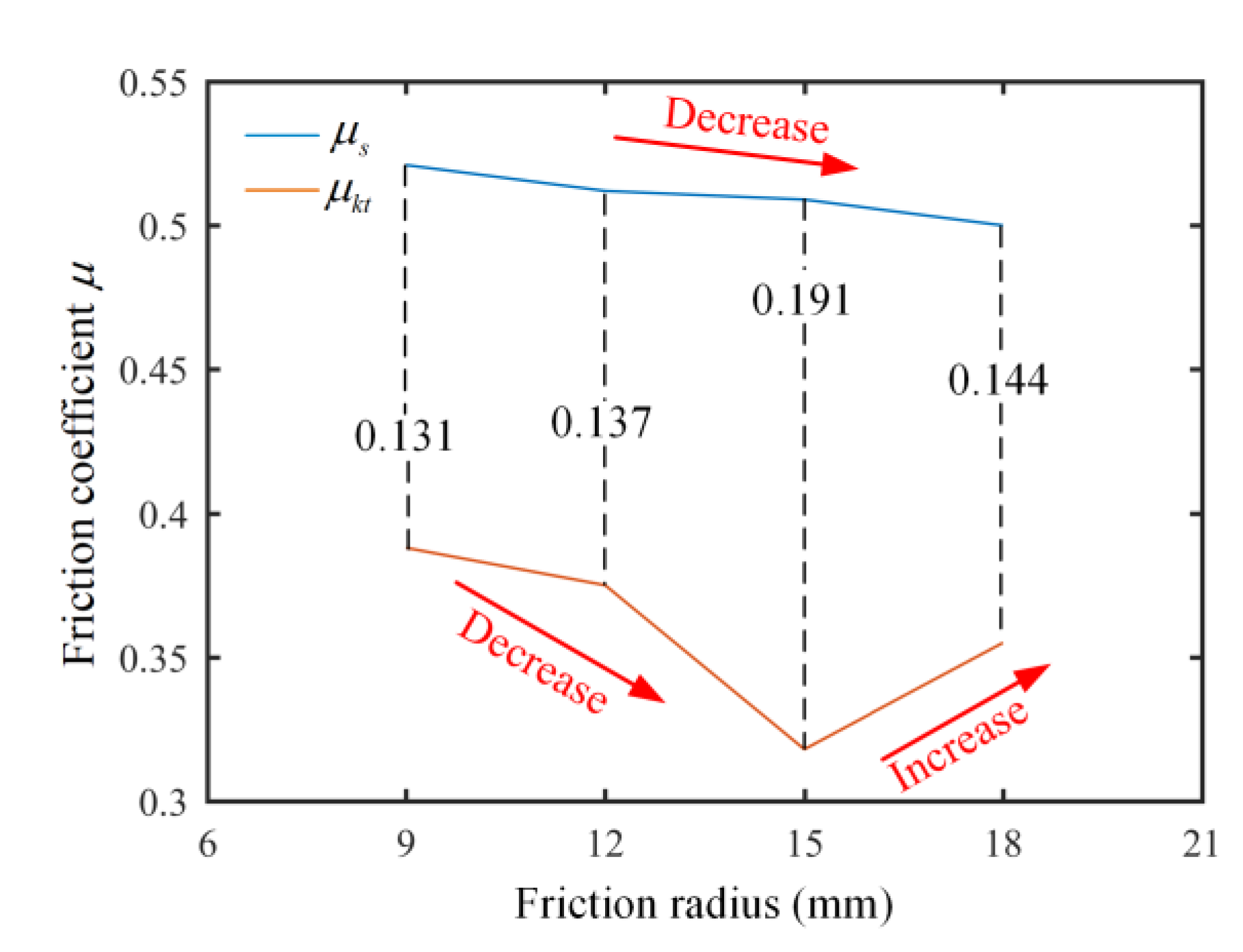
With the increase in the friction radius, the static friction coefficient decreased gradually and the dynamic friction coefficient decreased first and then increased. Furthermore, the variation trend of the difference between the dynamic and static friction coefficients was consistent with that of the stick–slip vibration amplitude.
(3).
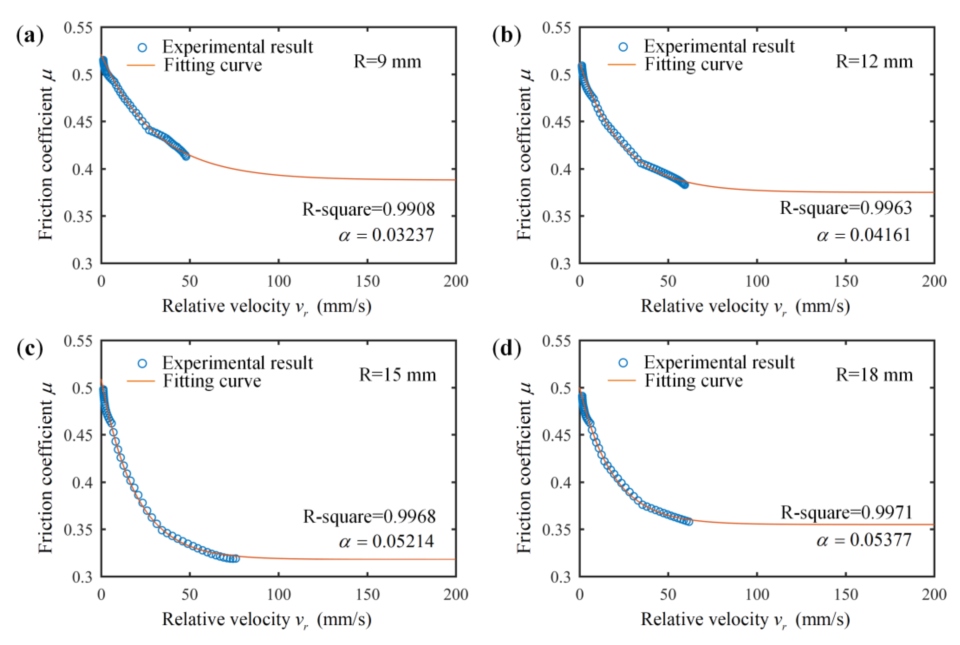
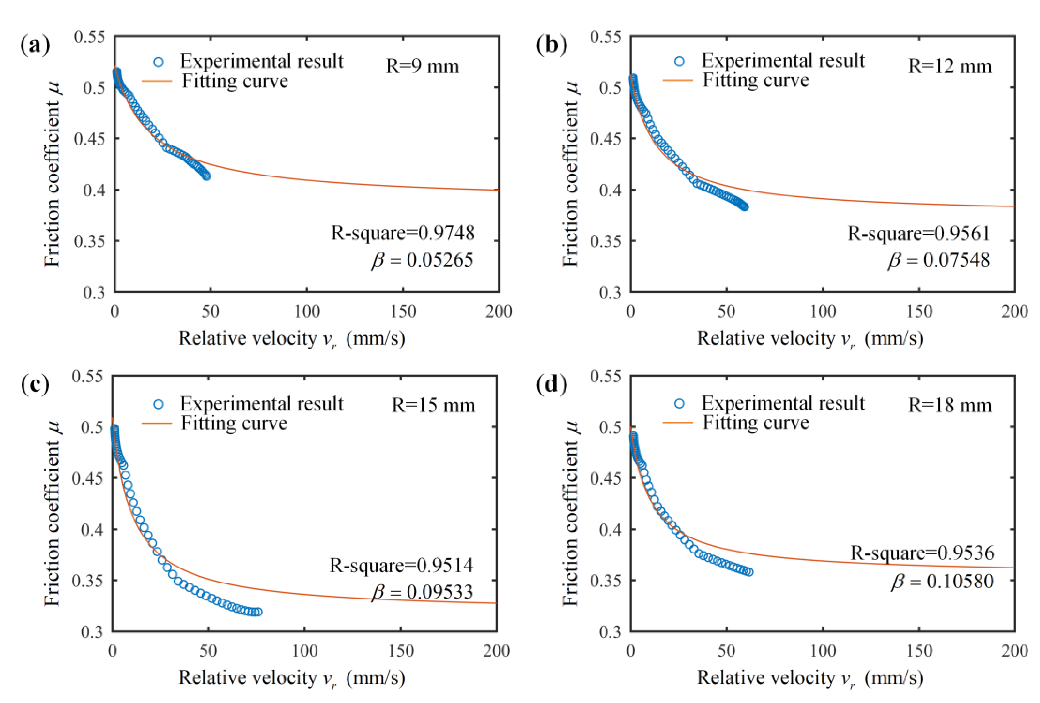
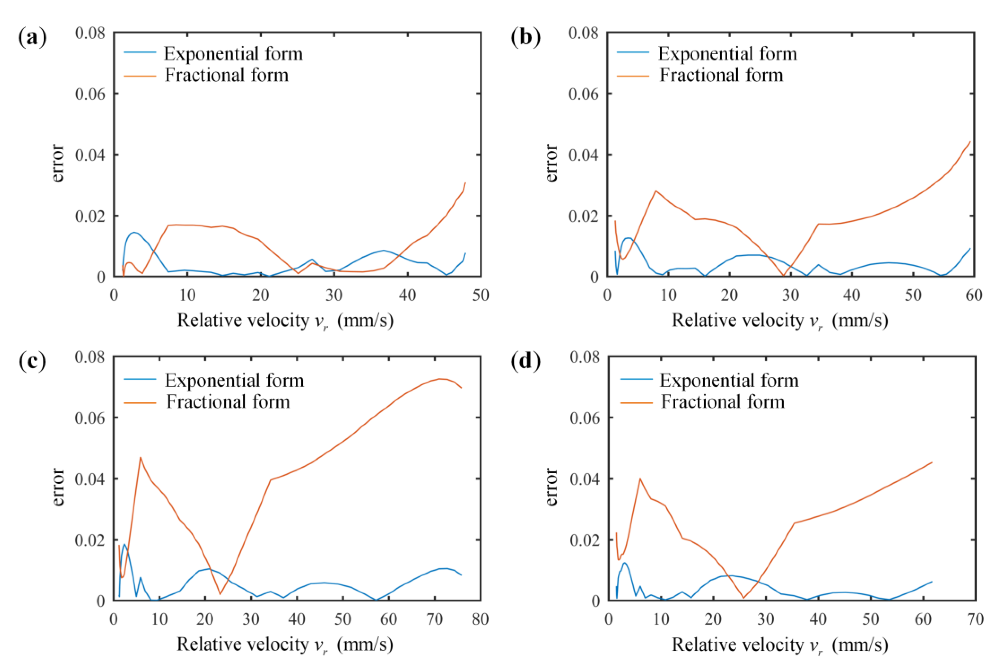
Both the exponential and fractional Stribeck friction models could effectively reflect the negative slope characteristics between the disc–block relative velocity and the friction coefficient, and the decay factors in the exponential and fractional forms increased with the increase in the friction radius. Moreover, the identified Stribeck model in its exponential form was more coincident with the stick–slip characteristics of the disc–block friction system than the model in its fractional form.
(4).
The severity of stick–slip vibration varied with the friction radius. In the real high-speed train braking system, to suppress or reduce its vibration, adjusting the friction radius is an option.

Author Contributions

Software, C.L.; formal analysis, C.L.; investigation, C.L. and Q.W.; data curation, C.L. and Q.W.; writing—original draft preparation, C.L. and Q.W.; writing—review and editing, Z.W., J.M., S.Z. and W.J.; project administration, J.M.; funding acquisition, Z.W. and J.M. All authors have read and agreed to the published version of the manuscript.

Funding

This research was funded by the National Natural Science Foundation of China (No. U22A20181 and 52205217), the Independent Research Projects of the State Key Laboratory of Traction Power (No. 2020TPL-T06), and the Natural Science Foundation of Sichuan (No. 2022NSFSC1964).

Data Availability Statement

Not applicable.

Conflicts of Interest

The authors declare no conflict of interest.

References

  1. Ghorbel, A.; Zghal, B.; Abdennadher, M.; Walha, L.; Haddar, M. Investigation of friction-induced vibration in a disk brake model, including mode-coupling and gyroscopic mechanisms. Proc. Inst. Mech. Eng. Part D-J. Automob. Eng. 2020, 243, 887–896. [Google Scholar] [CrossRef]
  2. Butlin, T.; Woodhouse, J. Sensitivity of friction-induced vibration in idealized systems. J. Sound Vib. 2009, 319, 182–198. [Google Scholar]
  3. Wang, Q.; Wang, Z.W.; Mo, J.L.; Zhang, L.; Du, L.Q.; Gou, Q.B. Coupled dynamic behaviours of the brake system considering wheel–rail interactions. Int. J. Rail 2021, 10, 749–771. [Google Scholar] [CrossRef]
  4. Zhang, L.; Wang, Z.W.; Wang, Q.; Mo, J.L.; Feng, J.; Wang, K.Y. The effect of wheel polygonal wear on temperature and vibration characteristics of a high-speed train braking system. Mech. Syst. Signal Process. 2023, 186, 109864. [Google Scholar] [CrossRef]
  5. Wang, Z.W.; Mei, G.M.; Xiong, Q.; Yin, Z.H.; Zhang, W.H. Motor car–track spatial coupled dynamics model of a high-speed train with traction transmission systems. Mech. Mach. Theory 2019, 137, 386–403. [Google Scholar] [CrossRef]
  6. Zeng, L.B.; Zhao, J.L.; Meng, Y.S. Vibrational fatigue failure prediction of a brake caliper used for railway vehicles based on frequency domain method. J. Phys. Conf. Ser. 2021, 1948, 012091. [Google Scholar] [CrossRef]
  7. Yuan, Q.; Tang, P.; Li, S.S. Topology optimization design of brake structure to reduce friction-induced vibration and noise. Mech. Sci. Technol. Aerosp. Eng. 2021, 40, 1391–1396. [Google Scholar]
  8. Gao, H.; Dai, H.Y. Disk brake element chatter analysis and strength evaluation for railway vehicle system. Mater. Prod. Technol. 2008, 44–46, 901–904. [Google Scholar] [CrossRef]
  9. Li, F.Z.; Tong, S.G. The Vibration and modal analysis of the disc brake. Adv. Mater. Res. 2013, 774–776, 78–81. [Google Scholar] [CrossRef]
  10. Moon. A study for failure examples of brake judder with abnormal vibration of disc brake. J. Korean Inst. Gas 2016, 20, 40–45. [Google Scholar] [CrossRef] [Green Version]
  11. Xiao, J.K.; Xiao, S.X.; Chen, J.; Zhang, C. Wear mechanism of Cu-based brake pad for high-speed train braking at speed of 380 km/h. Tribol. Int. 2020, 150, 106357. [Google Scholar] [CrossRef]
  12. Modanloo, A.; Talaee, M.R. Analytical thermal analysis of advanced disk brake in high speed vehicles. Mech. Adv. Mater. Struct. 2020, 27, 209–217. [Google Scholar] [CrossRef]
  13. Yang, G.; Yang, Y. Investigation on the thermal fatigue life evaluation method of railway brake disc with new material. Teh. Vjesn. Tech. Gaz. 2018, 25, 1095–1102. [Google Scholar]
  14. Zhou, Q.Z.; Wang, D.S.; Gao, S.Y.; Liu, B. Research advances of mechanisms and control methods of friction-induced braking noise. Noise Vib. Control 2017, 37, 1–5+218. [Google Scholar]
  15. Wang, A.Y.; Mo, J.L.; Wang, X.C.; Zhu, M.H.; Zhou, Z.R. Effect of surface roughness on friction-induced noise: Exploring the generation of squeal at sliding friction interface. Wear 2018, 402–403, 80–90. [Google Scholar] [CrossRef]
  16. Wang, D.W.; Mo, J.L.; Zhu, Z.Y.; Ouyang, H.; Zhu, M.H.; Zhou, Z.R. Debris trapping and space-varying contact via surface texturing for enhanced noise performance. Wear 2018, 396–397, 86–97. [Google Scholar] [CrossRef]
  17. Charroyer, L.; Chiello, O.; Sinou, J.J. Parametric study of the mode coupling instability for a simple system with planar or rectilinear friction. J. Sound Vib. 2016, 384, 94–112. [Google Scholar] [CrossRef] [Green Version]
  18. Tang, B.; Mo, J.L.; Xu, J.W.; Wu, Y.K.; Zhu, M.H.; Zhou, Z.R. Effect of perforated structure of friction block on the wear, thermal distribution and noise characteristics of railway brake systems. Wear 2019, 426–427, 1176–1186. [Google Scholar] [CrossRef]
  19. Xiang, Z.Y.; Chen, W.; Mo, J.L.; Liu, Q.A.; Fan, Z.Y.; Zhou, Z.R. The effects of the friction block shape on the tribological and dynamical behaviors of high-speed train brakes. Int. J. Mech. Sci. 2021, 194, 106184. [Google Scholar] [CrossRef]
  20. Tang, B.; Mo, J.L.; Xu, J.W.; Wu, Y.K.; Zhu, M.H.; Zhou, Z.R. Effect of the friction block shape of railway brakes on the vibration and noise under dry and wet conditions. Tribol. Trans. 2019, 62, 262–273. [Google Scholar] [CrossRef]
  21. Quan, X.; Mo, J.L.; Huang, B.; Tang, B.; Ouyang, H.J.; Zhou, Z.R. Influence of the Friction Block Shape and Installation Angle of High-Speed Train Brakes on Brake Noise. J. Tribol. 2020, 142, 031701. [Google Scholar] [CrossRef]
  22. Wu, Y.K.; Xu, J.W.; Wang, X.C.; Chen, W.; Lu, C.; Mo, J.L. The effect of damping components on the interfacial dynamics and tribological behavior of high-speed train brakes. Appl. Acoust. 2021, 178, 107962. [Google Scholar] [CrossRef]
  23. EL-Tayeb, N.S.M.; Liew, K.W. On the dry and wet sliding performance of potentially new frictional brake pad materials for automotive industry. Wear 2009, 266, 275–287. [Google Scholar] [CrossRef]
  24. Li, D.; Zheng, Z.C.; Gao, Y.; Shan, P.; Luo, W.; Liu, F.L.; Han, D.Y.; Zhang, Y.F.; Lv, Q.Y. Finite element analysis on the influence of the change of characteristic parameters of brake Pad on structural modal. IOP Conf. Ser. Earth Environ. Sci. 2020, 446, 052077. [Google Scholar] [CrossRef]
  25. Abdo, J.; Nouby, M.; Mathivanan, D.; Srinivasan, K. Reducing disc brake squeal through FEM approach and experimental design technique. Veh. Noise Vib. 2010, 6, 230–246. [Google Scholar] [CrossRef]
  26. Wei, D.G.; Wang, W.J.; Wang, B.; Wang, W.; Li, S.H.; Wu, D.; Jiang, P. Bifurcation and chaotic behaviors of vehicle brake system under low speed braking condition. J. Vib. Eng. Technol. 2021, 9, 2107–2120. [Google Scholar] [CrossRef]
  27. Stoica, N.A.; Petrescu, A.M.; Tudor, A.; Predescu, A. Tribological properties of the disc brake friction couple materials in the range of small and very small speeds. 13th Int. Conf. Tribol. (Rotrib’16) 2017, 174, 012019. [Google Scholar] [CrossRef] [Green Version]
  28. PASCAL, M. New events in stick-slip oscillators behaviour. J. Appl. Math. Mech. 2011, 75, 283–288. [Google Scholar] [CrossRef] [Green Version]
  29. Kato, S.; Yamaguchi, K.; Matsubayashi, T. Stick-Slip Motion of Machine Tool Slideway. J. Manuf. Sci. Eng. 1974, 96, 557–566. [Google Scholar] [CrossRef]
  30. Wu, W.X.; Brickle, B.V.; Smith, J.H.; Luo, R.K. An investigation into stick-slip vibrations on vehicle/track systems. Veh. Syst. Dyn. 1998, 30, 229–236. [Google Scholar] [CrossRef]
  31. Huang, B.; Wu, Y.; Wang, R.; Wang, X.; Ouyang, H.; Mo, J.L. Study of parameters of Stribeck model based on stick-slip oscillation experimental test. J. Anhui Polytech. Univ. 2020, 35, 1–8+100. [Google Scholar]
  32. Abdo, J.; Abouelsoud, A.A. Analytical approach to estimate amplitude of stick-slip oscillations. J. Theor. Appl. Mech. 2011, 49, 971–986. [Google Scholar]
  33. Wang, Z.W.; Zhang, Y. Research on nonlinear stick-slip motion behavior of automotive disc brake system via ABAQU. Mod. Manuf. Eng. 2020, 10, 62–69. [Google Scholar]
  34. Wang, X.C.; Wang, R.L.; Huang, B.; Mo, J.L. A study of effect of various normal force loading forms on frictional stick-slip vibration. J. Dyn. Monit. Diagn. 2021, 1, 46–55. [Google Scholar] [CrossRef]
  35. Meng, D.J.; Zhang, L.J.; Xu, X.T.; Sardahi, Y.; Chen, G.S. Sensing and Quantifying a New Mechanism for Vehicle Brake Creep Groan. Shock. Vib. 2019, 2019, 1843205. [Google Scholar] [CrossRef]
  36. Wang, Q.; Wang, Z.W.; Mo, J.L.; Zhang, L. Nonlinear behaviors of the disc brake system under the effect of wheel-rail adhesion. Tribol. Int. 2022, 165, 107263. [Google Scholar] [CrossRef]
  37. Li, C.B.; Pavelescu, D. The friction-speed relation and its influence on the critical velocity of stick-slip motion. Wear 1982, 82, 277–289. [Google Scholar]
  38. Van De Vrande, B.L.; Van Campen, D.H.; De Kraker, A. Approximate analysis of dry-friction-induced stick-slip vibrations by a smoothing procedure. Nonlinear Dyn. 1999, 19, 157–169. [Google Scholar] [CrossRef]
  39. Wei, D.G.; Ruan, J.Y.; Zhu, W.W.; Kang, Z.H. Properties of stability, bifurcation, and chaos of the tangential motion disk brake. J. Sound Vib. 2016, 375, 353–365. [Google Scholar] [CrossRef]
  40. Bouc, R. Forced Vibration of Mechanical System with Hysteresis. In Proceedings of the Fourth Conference on Nonlinear Oscillations, Prague, Czech Republic, 5–9 September 1967; p. 315. [Google Scholar]
  41. Wen, Y.K. Method of fandom vibration of hysteretic systems. ASCE J. Eng. Mech. Div. 1976, 102, 1069–1089. [Google Scholar]
  42. Zhu, W.W. Dynamics Analysis of Stability, Bifurcation, and Chaos of Vehicle Brake Groan at Low Speeds. Master’s Thesis, Hefei University of Technology, Hefei, China, 2016. [Google Scholar]
Figure 1. Differences in brake block radii in high-speed train braking system.
Vehicles 05 00003 g001
Figure 2. Experimental device.
Vehicles 05 00003 g002
Figure 3. Experimental samples: (a) disc and (b) block.
Vehicles 05 00003 g003
Figure 4. Curves of the Stribeck model in two forms.
Vehicles 05 00003 g004
Figure 5. RMS values and error bars of tangential velocities under four friction radius conditions.
Vehicles 05 00003 g005
Figure 6. Time-domain responses of the disc–block relative velocity at different friction radii: (a) 9 mm, (b) 12 mm, (c) 15 mm, (d) 18 mm.
Vehicles 05 00003 g006
Figure 7. Frequency-domain responses of the disc–block relative velocity at different friction radii: (a) 9 mm, (b) 12 mm, (c) 15 mm, (d) 18 mm.
Vehicles 05 00003 g007
Figure 8. Time-domain responses of the disc–block friction coefficient at different friction radii: (a) 9 mm, (b) 12 mm, (c) 15 mm, (d) 18 mm.
Vehicles 05 00003 g008
Figure 9. Dynamic and static friction coefficients at different friction radii.
Vehicles 05 00003 g009
Figure 10. Experimental results and fitting curves of the exponential Stribeck model at different friction radii: (a) 9 mm, (b) 12 mm, (c) 15 mm, (d) 18 mm.
Vehicles 05 00003 g010
Figure 11. Experimental results and fitting curves of the fractional Stribeck model at different friction radii: (a) 9 mm, (b) 12 mm, (c) 15 mm, (d) 18 mm.
Vehicles 05 00003 g011
Figure 12. Relative errors of the exponential and fractional forms of the Stribeck model at different friction radii: (a) 9 mm, (b) 12 mm, (c) 15 mm, (d) 18 mm.
Vehicles 05 00003 g012
Table 1. Chemical composition of the disc sample.
ElementFeSiMnCNiCrMo
Content (wt%)Balance0.250.750.311.81.10.5
Table 2. Chemical composition of the block sample.
ElementCuFeGraphiteMoS2FeCrSiCOthers
Content (wt%)45–5013–1518–204–66–82–43–5
Table 3. Material properties of the disc and block test samples.
SampleDensity (g/cm3)Young’s
Modulus (GPa)
Poisson’s Ration
Disc7.81780.3
Block4.76.50.28
Table 4. Stribeck model parameters at different friction radii.
Friction RadiusStatic Friction CoefficientDynamic Friction CoefficientExponential Decay FactorFractional Decay Factor
9 mm0.5210.3880.032370.05265
12 mm0.5120.3750.041610.07548
15 mm0.5090.3180.052140.09533
18 mm0.5000.3550.053770.10580
Disclaimer/Publisher’s Note: The statements, opinions and data contained in all publications are solely those of the individual author(s) and contributor(s) and not of MDPI and/or the editor(s). MDPI and/or the editor(s) disclaim responsibility for any injury to people or property resulting from any ideas, methods, instructions or products referred to in the content.

