1. Introduction
With air bearings, rotors can be supported without lubrication or friction. Therefore, air-bearings are widely-used, for example in micro-turbines and paint-spraying spindles as well as for other small and/or fast-rotating shafts. Air bearings strongly influence the dynamic behavior of rotor systems. However, the stiffness and damping properties required for rotordynamic analyses are poorly documented for aerodynamic cylindrical bearings and simple calculation methods are lacking.
In contrast, commercial finite element programs today often have special element types for the analysis of hydrodynamic cylindrical bearings, which simplifies the calculation considerably and makes numerical simulations of entire rotor-bearing systems accessible to a wide range of users. Such a pragmatic calculation methodology would also be desirable for aerodynamic cylindrical bearings.
Based on the similarity between aerodynamic and hydrodynamic cylindrical bearings it is, therefore, investigated here and in [
1] to what extent the element types for hydrodynamic bearings available in the commercial FE program ANSYS [
2], are also suitable for the calculation of aerodynamic bearings. However, the compressibility of the gas—the only significant difference to lubricating oils—is neglected within the calculations with these hydrodynamic element types.
For this purpose, the quality of the hydrodynamic element types available in ANSYS is first validated on known hydrodynamic radial cylindrical bearings [
3,
4] within this investigation. Assuming that the compressibility of the gas might be negligible due to the very thin bearing gap, the stiffness and damping coefficients for a simple aerodynamic radial cylindrical bearing without additional orifices for the air supply are calculated with the available hydrodynamic ANSYS element types subsequently. This step involves the application of known and proven algorithms for calculating hydrodynamic bearings on a different bearing type for which the algorithms have not been meant initially. By comparing the calculation results for the aerodynamic bearings with literature reference data [
5], this new approach is evaluated considering the suitability of the hydrodynamic element types for aerodynamic journal bearings. This investigation is limited to aerodynamic radial cylindrical bearings with a bearing width ratio
.
The good agreement between the calculated stiffness and damping coefficients for aerodynamic radial cylinder bearings and the literature reference data [
5] shows that the available hydrodynamic journal bearing types in the FE program ANSYS can also be used for calculating the stiffness and damping coefficients of aerodynamic journal bearings. So, the compressibility of the gas in the bearing gap can in fact be neglected for plain aerodynamic bearings in the operating range considered. Standard finite element types for hydrodynamic bearings may, therefore, as well be used for aerodynamic bearings which offers a very simple and pragmatic calculation method for this bearing type to a wide range of commercial FE program users.
2. State of the Art
Various calculation methods have been developed in the past for the dynamic analysis of hydrodynamic and aerodynamic journal bearings. Computational fluid dynamics (CFD) analyses, e.g., [
6], are based on the numerical solution of the Navier–Stokes equation and the continuity equation and thus offer very high accuracy for the calculation of the flow in the lubrication gap [
7]. Taking into account some special properties of the lubricant flow in a journal bearing, the Navier–Stokes equation and the continuity equation can be simplified to the so-called Reynolds equation [
4,
8]. For hydrodynamic cylindrical bearings, analytical solutions for very short or infinitely wide cylindrical bearings have been known for a long time [
4], and recently also for cylindrical bearings of arbitrary widths, [
9], but not for aerodynamic cylindrical bearings.
In practice, numerical solutions of the Reynolds equation with finite difference methods (FDM) and the finite element method (FEM) are widely used [
7]. Naturally, the simplifications for deriving the Reynolds equation and its numerical solution cause a lower accuracy compared to CFD analyses, but also result in a lower computational effort [
7].
The dynamic analysis of entire rotor-bearing systems, for example [
10], additionally requires the consideration of the rotor and other relevant components. Multi-physic co-simulation approaches combine the calculation of the lubricant flow with, for example, multi-body simulations (MBS) or finite element analyses (FE analyses) to analyze the entire system, e.g., [
11]. However, co-simulation requires a very high effort in modelling and calculation [
7], which often exceeds the possibilities in industrial practice. Particularly attractive and far less time-consuming is the possibility of carrying out both the journal-bearing calculation and the analysis of the rotor-bearing system with a finite element analysis in one single development environment. For hydrodynamic journal bearings, this is already implemented in common FE programs, e.g., in ANSYS [
2], but not for aerodynamic bearings.
Another widely used method for considering the dynamic properties of journal bearings is using linearised stiffness and damping coefficients. The stiffness and damping coefficients depend on the rotational speed or bearing load capacity and can be directly incorporated into the equations of motion of the rotor [
4,
8,
10]. These coefficients can be determined experimentally or numerically in advance or can be taken from the literature so that the Reynolds equation does not have to be solved again. This keeps the modelling and calculation effort for rotordynamic simulations manageably small.
Unfortunately, there are only few data available in the literature addressing the stiffness and damping coefficients of aerodynamic cylindrical bearings, e.g., [
5,
12]. Therefore, a method for calculating the stiffness and damping coefficients of aerodynamic bearings as simply as possible is required to make this rotordynamic simulation concept applicable also to aerodynamic bearings and available for many engineers who have a common FE program at their disposal.
The numerical calculation of the stiffness and damping coefficients is usually based on the Reynolds equation, which describes the pressure
in the lubrication gap [
8]. For a hydrodynamic cylindrical bearing according to
Figure 1 with an incompressible fluid of the dynamic viscosity
, with a shaft radius
and a radial bearing clearance
, with the lubrication gap height
along the circumferential coordinate
and along the bearing axial coordinate
, and with the circumferential speed
of the bearing journal, the Reynolds equation according to [
8] is
Considering the compressibility of gases, the Reynolds equation for aerodynamic cylindrical bearings according to [
5] results in
Due to the compressibility of the gas, the spatial rate of change of the pressure and the variability of the viscosity are additionally taken into account.
With reference to the ambient pressure
, the influence of gas compressibility in aerodynamic bearings is characterised by the dimensionless speed number [
5],
For values
, the gas behaves like an incompressible fluid [
5].
The component-wise integration of the pressure distribution
over the bearing gap results in the load-bearing force
of the journal bearing [
4,
13]. The load capacity
, the shaft’s rotational frequency
and the journal bearing parameters, which are the relative bearing clearance
, the bearing width
and the dynamic viscosity
of the lubricant, characterise the operating condition of the bearing, which is summarised in the dimensionless Sommerfeld number [
13]:
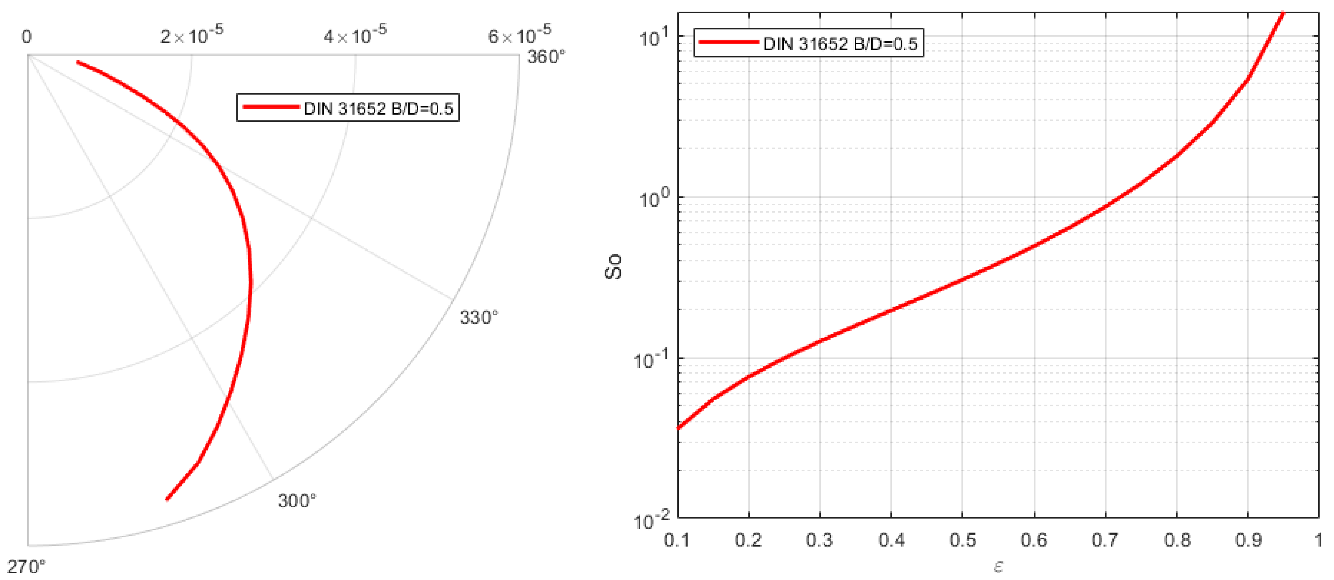
For each operating condition of the bearing, the shaft takes a certain equilibrium position, the so-called stationary operating point, at a certain relative displacement eccentricity
and a certain displacement angle
, see
Figure 2 [
13]. For hydrodynamic journal bearings, DIN 31652 [
3], specifies both the corresponding displacement angle
and the operating condition
as a function of the displacement eccentricity
(see
Figure 2), from which the load capacity of the bearing can be determined. In the Cartesian bearing coordinates according to
Figure 1, the stationary relative rotor displacement is
For small oscillations of the shaft around the stationary operating point, the change of the load capacity
can be interpreted as linearised spring and damping forces depending on the additional displacements
and on the displacement velocities
as well as on the stiffness coefficients
and the damping coefficients
[
8]:
with
and
(analogously for the other coefficients).
The stiffness and damping coefficients also depend on the operating condition of the bearing.
For numerous designs and sizes of hydrodynamic journal bearings, the stiffness and damping coefficients have been determined in the past both numerically from the solution of the Reynolds equation and experimentally in numerous tests, e.g., [
3,
14]. For the stiffness and damping coefficients of aerodynamic journal bearings, however, far fewer reference data are available in the literature, e.g., [
5,
12].
3. Modelling Journal Bearings with ANSYS
For the present investigation, ANSYS Mechanical APDL was used [
2]. Its element library contains the element types COMBI214 and FLUID218 for hydrodynamic journal bearings. Both element types use the numerical solution of the Reynolds Equation (1) and internally calculate the pressure distribution in the bearing. This requires information on the bearing geometry, the lubricant properties, the speed and the stationary operating point. From the pressure distribution along the bearing gap and the resulting load capacity, the stiffness and damping coefficients can then be calculated for both element types using different procedures.
3.1. ANSYS Element COMBI214
The ANSYS element COMBI214 is a 2-node segment element, which represents the entire cylindrical bearing in its full width [
1]. Thus, the bearing is not described as a 3D object and no local points on the surface of the bearing shell can be modelled. Lubrication pockets, orifices or even microporous bearing shells cannot be considered.
The bearing is described by COMBI214 according to
Figure 3 with the geometrical bearing parameters of bearing width
, shaft radius
, radial bearing clearance
as well as with the physical bearing parameters viscosity
and shaft rotational frequency
. In addition to the stationary operating point
, also the pressure boundary condition must be specified at the open edges.
The calculation procedure for COMBI214 solves the Reynolds Equation (1) and determines the bearing force from the pressure distribution. Optionally, the stiffness coefficients and the damping coefficients of the bearing can also be calculated. Alternatively, the element COMBI214 can also be used as an input container for stiffness and damping coefficients that are known from other calculation applications or experiments.
By automatically determining the stiffness and damping coefficients in only one single calculation process, the advantages of the COMBI214 element are simple handling, a less time-consuming and cost-intensive calculation, and thus greater user-friendliness with regard to rotor dynamic simulations.
3.2. ANSYS-Element FLUID218
The ANSYS element FLUID218 is a 4-node shell element, with which the surface of the lubricating film of a journal bearing can be modelled and discretised [
2]. As this is a 3D model of the whole lubricating film, also lubrication pockets, orifices or even multi-surface sliding bearings can be modelled.
The bearing is described by FLUID218 according to
Figure 4 with additional geometric and physical bearing parameters. The element thickness along the circumference is variable and results from the stationary operating point (
) and the relative bearing clearance
. The pressure at the free edges is to be given as boundary conditions.
The calculation process for the element type FLUID218 only includes the calculation of the pressure distribution from the numerical integration of the Reynolds Equation (1). Additional values must be determined by the user through programming. The user must, therefore, be able to control the output himself.
As explained above, the additional dynamic forces for small movements around the stationary operating point can be expressed by using stiffness and damping coefficients. A small disturbance of the stationary operating point leads to a slightly changed bearing force. From the given disturbances and the change in the bearing force, the desired coefficients can then be calculated according to Equation (6). For determining all coefficients, four disturbances are necessary. So, the pressure distribution in the bearing and the forces have to be calculated five times.
Together with the manual process control, this means a much higher time and cost effort compared to the element type COMBI214, but is still far less time-consuming than fluid-structure co-simulations, as all calculations are performed within a single FE program.
4. Validation of the ANSYS Element Types for Hydrodynamic Radial Cylinder Bearings
Before applying the hydrodynamic element types to aerodynamic bearings, the quality of the elements is first checked using data from known hydrodynamic radial cylinder bearings [
3,
4]. A bearing with a diameter of
and other bearing characteristics according to
Table 1 and
Figure 5 serves as a validation example. The stationary operating point is specified variably over the entire lubrication gap according to DIN 31652 [
3]. The boundary conditions incorporate ambient pressure at the outer bearing rims, see
Figure 5 on the left.
The hydrodynamic cylinder bearing validation examples are modelled with both the element type COMBI214 and the element type FLUID218. For element type FLUID218, a sensitivity analysis was conducted to determine a suitable element size to ensure good simulation results at a low calculation time and cost. By reducing the mesh size step by step and checking the convergence of the solution, a regular mesh with almost quadratic elements of about 2 mm edge length and round about 2° circumferential resolution (as shown in
Figure 5) was created for the example hydrodynamic bearing according to
Table 1. The aspect ratio is about 1 for the whole mesh. For element type COMBI214, a sensitivity analysis is not necessary as this element type models the whole bearing in only one single element.
According to
Section 3, the pressure distribution, the load capacity, and the stiffness and damping coefficients are then calculated for both element types COMBI214 and FLUID218. In addition, the bearing validation examples are calculated with the tool GLKOEF [
15], which determines the stiffness and damping coefficients from the specified stationary operating point and the bearing properties by integrating the Reynolds equation for hydrodynamic cylindrical bearings according to DIN 31652 [
3].
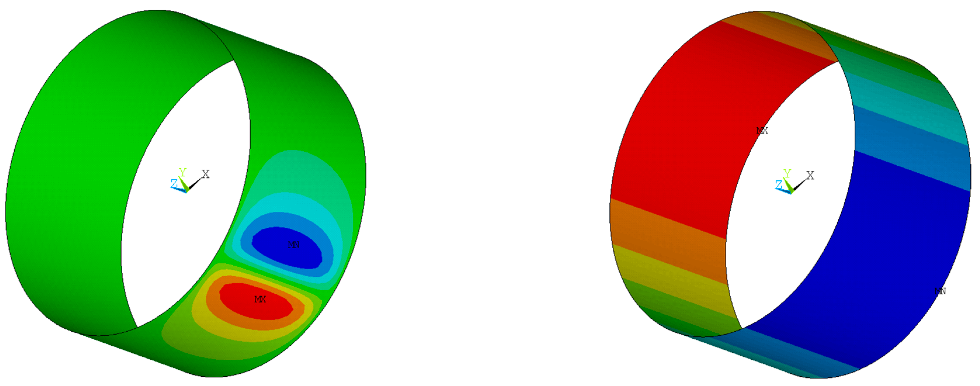
Figure 6 shows an example of the pressure distribution and the lubrication film thickness for the bearing validation example with a relative bearing width of
. The results correspond to the expectations by showing a definite pressure maximum and minimum along the circumferential center line decreasing in the axial direction and meeting the ambient pressure boundary conditions at the bearing rims, see
Figure 6 on the left. Additionally, the bearing gap thickness in
Figure 6 on the right confirms the initially given eccentric rotor position according to the stationary operating point
.
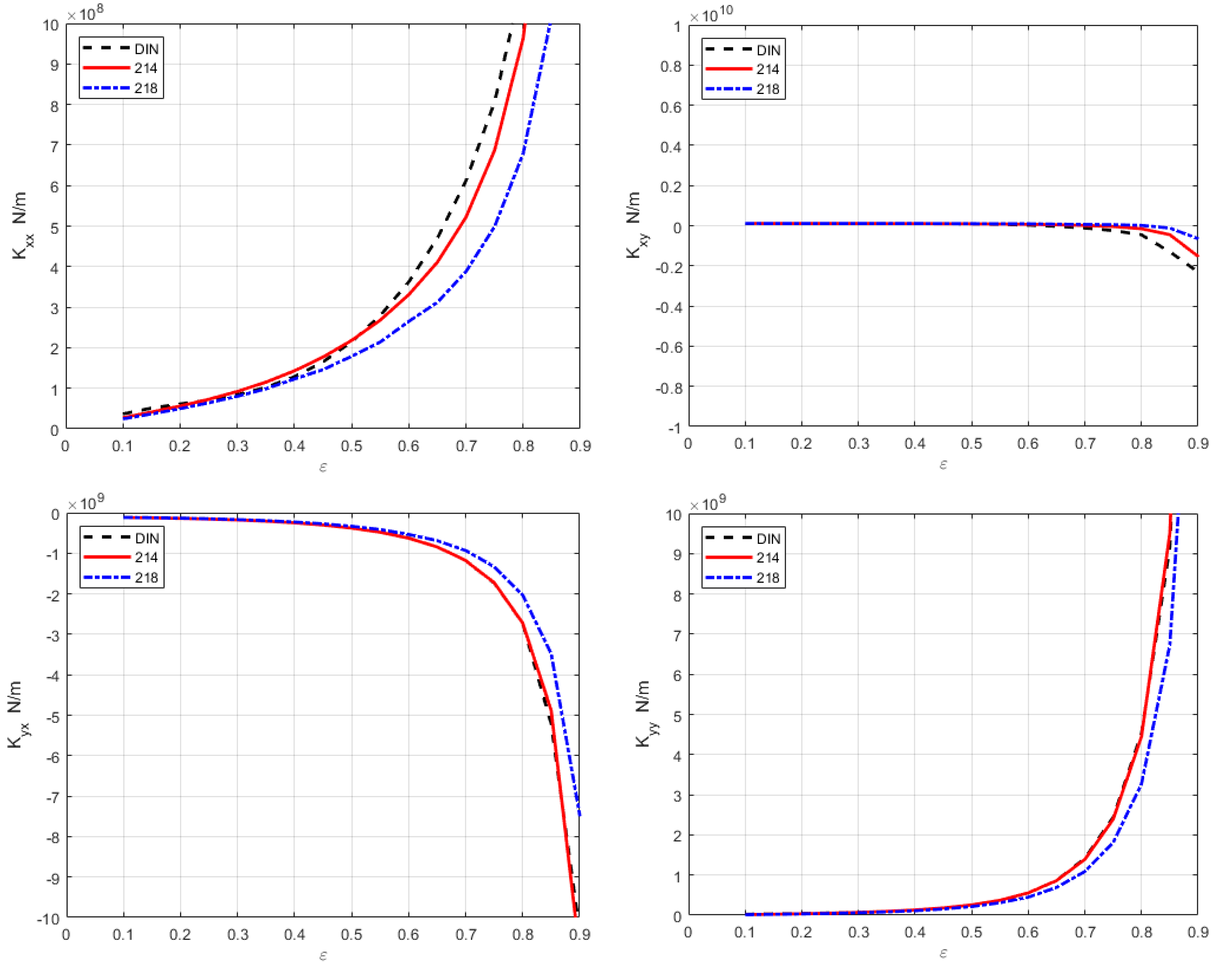
Figure 7 and
Figure 8 compare the stiffness and damping coefficients for both hydrodynamic element types COMBI214 and FLUID 218 with the literature values [
3] for the hydrodynamic cylindrical bearing with an exemplary relative bearing width of
. Both ANSYS element types do not only provide consistent results compared to each other and compared to literature data, but also for all other relative bearing widths tested.
Therefore, the quality of the ANSYS element types for hydrodynamic cylindrical bearings as well as the application methodology can thus be considered to be certain.
5. Aerodynamic Radial Cylinder Bearings
The suitability of the hydrodynamic ANSYS element types for aerodynamic journal bearings is now checked for aerodynamic radial cylinder bearings without additional orifices. The bearing examples investigated, see
Table 2, are based on the only comparative data available in the literature by San Andres [
5], for a turbopump bearing, and Czolczynski [
12]. The literature values were both determined by taking into account the compressibility of the gas.
The modelling and calculation are analogous to the hydrodynamic cylindrical bearings. Here, too, the pressure distribution, the load capacity, the lubricant film thickness as well as the stiffness and damping coefficients are calculated according to
Section 3 for both element types. In addition, the stiffness and damping coefficients are calculated with the tool GLKOEF [
15].
The calculated pressure distribution of the aerodynamic cylindrical bearing is qualitatively very similar to that of the hydrodynamic cylindrical bearing, whereby the (maximum) pressure in an aerodynamic cylindrical bearing is significantly lower than in a hydrodynamic cylindrical bearing of similar geometry due to the smaller viscosity of the lubricant. The load capacity of aerodynamic journal bearings is thus significantly lower compared to hydrodynamic journal bearings of the same design.
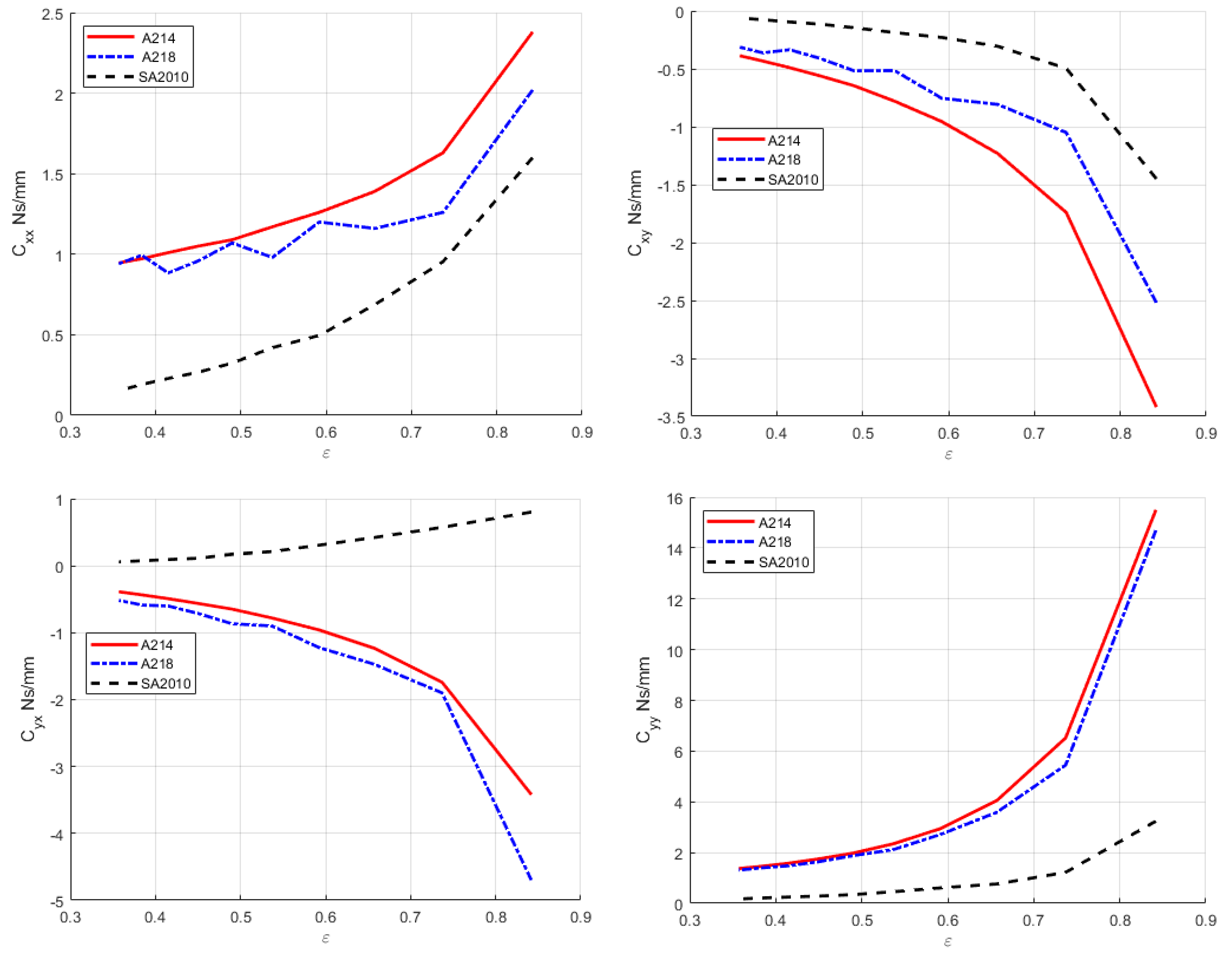
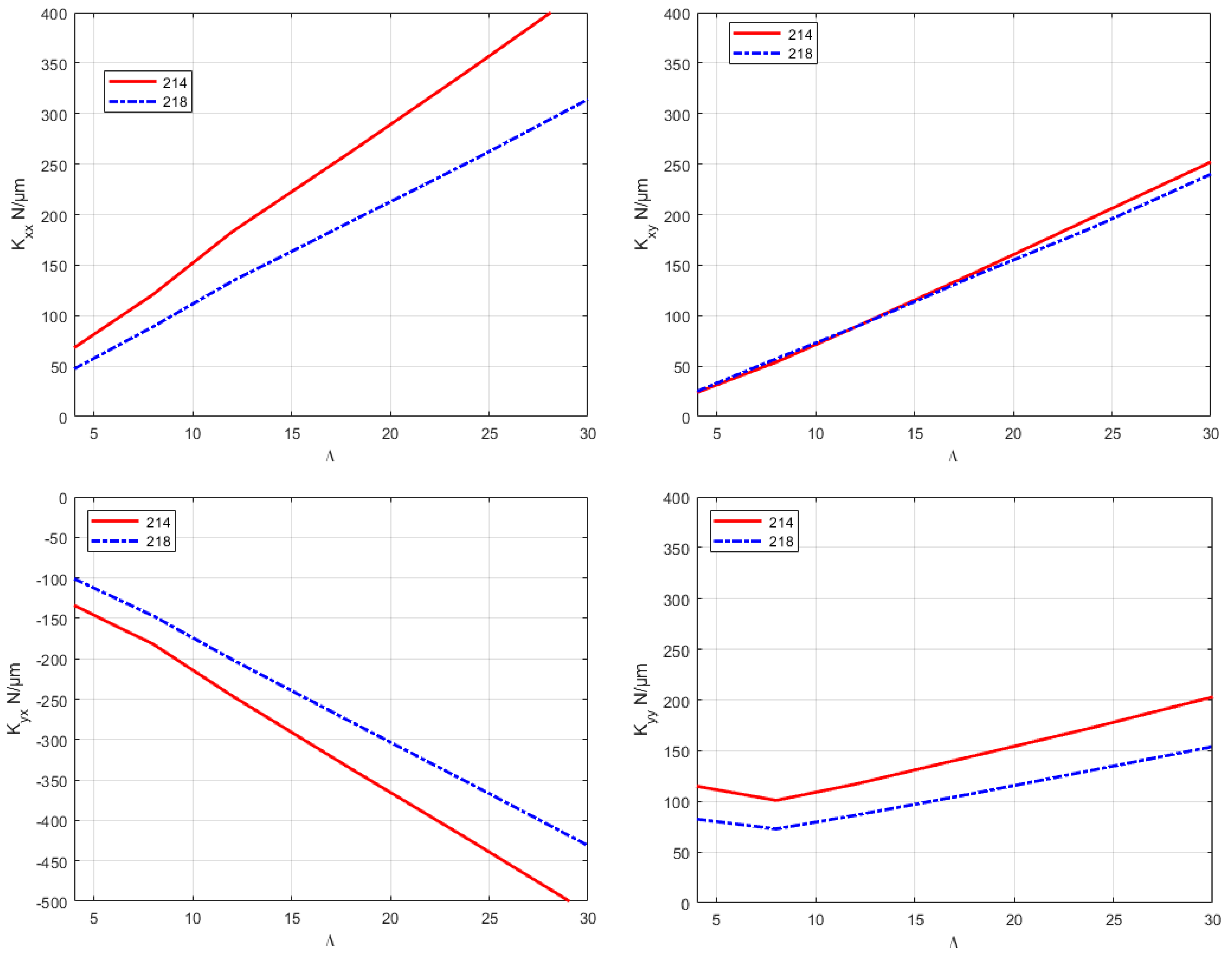
Figure 9 and
Figure 10 compare the stiffness and damping coefficients calculated for the relatively small Bearing 1 for the element types COMBI214 and FLUID218 with the corresponding literature data from [
5]. First of all, a noticeable difference between the stiffness and damping coefficients calculated with both hydrodynamic element types COMBI214 and FLUID218 shows a general uncertainty within the calculated values. The reason for that is the different discretization and the different calculation methods for both element types. This effect can also be noted to a smaller extent for the stiffness and damping coefficients for hydrodynamic bearings in
Figure 7 and
Figure 8.
Both the stiffness and damping coefficients
and
, respectively,
and
for direct coupling (on the main diagonal of the stiffness and damping matrix) for both ANSYS element types agree quite well with the literature data in wide ranges as the difference is more or less in the same range as the difference between the two ANSYS element types. The differences between the cross-coupling stiffness and damping coefficients
and
, respectively,
and
(on the side diagonal of the stiffness and damping matrix) and the literature data are larger but still within an acceptable range as the cross-coupling influence usually is much smaller than that of the direct coupling. In general, the stiffness and damping coefficients for both hydrodynamic and aerodynamic journal bearings vary within a larger range [
5,
10,
12,
14]. To sum up, the obtained results show a good or acceptable agreement of the stiffness and damping coefficients calculated with the hydrodynamic element types with the literature data [
5].
The comparison of the stiffness and damping coefficients for the significantly larger Bearing 2 in
Figure 11 and
Figure 12 also shows a very good agreement between the two element types COMBI214 and FLUID218. Therefore, a significant size influence has not to be assumed for the calculation with the ANSYS elements.
However, a direct comparison of the stiffness and damping coefficients for Bearing 2 with the values of Czolczynski [
12], is not possible, because this study uses a different calculation method for determining the stiffness and damping coefficients. In Czolczysnki’s method, the shaft performs kinematically forced small oscillations of either
or
with amplitudes
and dimensionless angular frequencies
within the dimensionless time
around the static equilibrium position, [
12] (p. 31ff., p. 149). From the resulting bearing force
, the stiffness and damping coefficients are then calculated analogously to Equation (6). In contrast, the present calculation method uses statically disturbed operating points of the rotor, which would refer to a frequency
, for calculating the resulting bearings forces and determining the stiffness and damping coefficients. Because of the different frequencies of
on the one hand and
on the other, a direct comparison of the derived stiffness and damping coefficients is not possible. Due to locally large stiffness and damping coefficient gradients and poor printing quality in [
12], an extrapolation does not appear reasonable. Nevertheless, the stiffness and damping coefficients for the smallest frequency
derived by Czolczynski [
12], are in the same order of magnitude as the values calculated in the present study with ANSYS.
Due to the good agreement of the stiffness and damping parameters with the literature data [
5], good suitability of the hydrodynamic ANSYS element types COMBI214 and FLUID218 can be assumed for the calculation of aerodynamic cylinder bearings in the investigated operating range. For aerodynamic radial cylinder bearings, the gas compressibility in the very thin lubricating film apparently has only a minor influence.
6. Conclusions
In this work, it was investigated to what extent the hydrodynamic element types available in the finite element software ANSYS are also suitable for aerodynamic cylindrical bearings. For this purpose, the quality of the element types COMBI214 and FLUID218 was first verified by comparing the stiffness and damping coefficients of hydrodynamic cylindrical bearings with a relative width of
with known literature data [
3] and the results of the calculation tool GLKOEF, [
15]. Subsequently, different variants of aerodynamic radial cylinder bearings were modelled and calculated with these element types while neglecting the compressibility of the gas, and the results were compared with literature data. For purely aerodynamic radial cylinder bearings, the calculated stiffness and damping coefficients agree well with the literature data [
5] and are in the same order of magnitude as the literature values [
12], which are comparable only to a limited extent. The data of both [
5] and [
12] were determined taking into account the compressibility of the gas. It was thus shown that the gas compressibility in the very thin lubricating film has only a minor influence on the calculation of the aerodynamic journal bearing stiffness and damping properties. Therefore, the element types for hydrodynamic cylindrical bearings are also well suited for the calculation of aerodynamic radial cylinder bearings in the operating range considered.
With this pragmatic calculation approach, aerodynamic cylindrical bearings can also be successfully handled in standard finite element programs. Thus, the dynamics of complex rotor-bearing systems—also incorporating other components such as disks and blades, other bearing types, housing, etc.—can be calculated in a single development environment with relatively little effort and cost.
In the future, the investigations can be extended to full rotor-bearing-system simulations using the ANSYS hydrodynamic element types. As other recent studies use completely different simulation approaches for rotor-bearing systems, it should then be checked if the results obtained with the presented new method using hydrodynamic element types agree with the results from other simulation approaches.
Further, it could be checked whether the presented calculation approach can also be extended for aerodynamic bearings with orifices and porous air bearings. By using the ANSYS element type FLUID218, orifices and pores could be modelled by defining special inlet pressure boundary conditions at the orifices, respectively, at several places on the bearing shell surface.
Since the comparative values from the literature were all determined numerically, an experimental validation of the stiffness and damping coefficients would also be desirable.


