Article

Antennas in the Internet of Vehicles: Application for X Band and Ku Band in Low-Earth-Orbiting Satellites

Department of Electronic Engineering, National Taipei University of Technology, Taipei 10608, Taiwan
*
Author to whom correspondence should be addressed.
Vehicles 2023, 5(1), 55-74; https://doi.org/10.3390/vehicles5010004
Submission received: 27 October 2022 / Revised: 30 November 2022 / Accepted: 1 December 2022 / Published: 4 January 2023
(This article belongs to the Special Issue Internet of Vehicles and Vehicles Engineering)

Abstract

:
This paper proposes a simple and small-dimensioned antenna that can provide X band and Ku band for the low-earth-orbiting (LEO) satellite system in an Internet of vehicles system. The antenna is designed on the substrate Arlon DiClad 880. The antenna structure consists of an inverted triangle geometry and an inverted U-shaped slot. The dimensions of the antenna are 12.5 × 5 mm2, and the area of the substrate is 30 × 13 × 0.254 mm3. The antenna is easy to make, and the manufacturing cost is low. The measurement results of the reflection coefficient (lower than −10 dB) of the antenna show that the working frequency band can cover the X-band (10.87–12.76 GHz) and the Ku band (15.19–16.02 GHz). The measured and simulated results are fairly similar. The efficiency of the antenna in the X-band is about 50–80.8%. The efficiency of the antenna in the Ku-band is about 50–74%. The gains of the antennas are about 3.34–6.08 dBi and 3.50–4.65 dBi in the X-band and Ku band, respectively, and the highest gain is 6.08 dBi. The antenna design can realize the features of low cost and small dimensions in autonomous vehicles and vehicle networking communication system equipment and achieve good wireless transmission capabilities from vehicles to the base station in the IOV.

1. Introduction

In recent years, the demand for antennas for use in automotive communication systems has continued to increase, which has caused research on the Internet of vehicles (IOV) [1], such as vehicle-to-everything (V2X), vehicle-to-vehicle (V2V), vehicle-to-network (V2N) and In-vehicle Infotainment (IVI) communication, to flourish [2,3]. In the future, the Intelligent Transportation System (ITS) will be able to obtain real-time traffic information, such as road conditions, road information, and pedestrian information through the connection of the Internet of vehicles and the base station, which can also improve driving safety, avoid traffic congestion, and improve transportation efficiency [4]. Furthermore, currently, people are using cars more and more often to move to their destinations, and cars are fully integrated into our lives. Based on the above reasons, improving road traffic safety is an important topic, hence the emergence of intelligent vehicle technology research and development [5]. The rapid development of the Internet of vehicles (IOV) and the promotion of new technologies bring great convenience to our lives and transportation. It has also helped governments in various countries and regions effectively control the use of roads and highways and improve road safety. In addition, with the development of vehicle communication technology, V2X and satellite communication antennas in the ITS have also attracted great attention [6].
In addition to V2V connections with roadside units (RSUs) and nearby vehicles, each vehicle is also connected to satellites [7]. For vehicle-to-vehicle connection, the key technologies of the current vehicle communication system also bring development to the research of LEO satellite antennas [8,9]. In the V2X communication system, in addition to maintaining higher safety during vehicle driving, such as through vehicle distance and remote driving, V2X also includes V2V and vehicle-to-infrastructure (V2I) connections. It offers many advanced features, such as blind spot detection, forward distance warning, emergency vehicle approach warning, and road condition data, for predicting the shortest route to a destination and the safest driving conditions, all of which require a high-performance antenna to maintain a stable connection [10,11].
Low-earth-orbiting (LEO) satellite communication is also an essential technology for IOV communication. LEO satellites are currently deployed in the Ku band, Ka band, and Q/V band [12]. Therefore, many connected vehicle devices are also developing toward these frequency bands. The rapid development of these infrastructures will affect the connection between the IOV and autonomous vehicles [13]. IOV devices require antennas to achieve stable connections. Therefore, the antennas require a wideband and multi-band design to achieve high-data-volume signal transmission. Broadband also makes accommodating various wireless communication design standards in one device easier. In addition, the communication system also grasps certain variables, such as pressure, humidity, or temperature, when connecting devices. These environmental variables are also considerations when designing antennas [14]. IOV devices are small, compact, and easy to install in the desired environment. Therefore, the design of the antenna must meet the small size specifications without affecting the performance of the antenna.
Furthermore, designing antennas on particular substrates, such as car windows or windshields, is also challenging because of the limited area that the antenna can use. Therefore, only very thin conductive strips can be used, which also makes designing and installing the antenna more complex [15]. Antenna design should be considered a top priority regardless of the wireless communication product. Therefore, antenna engineers must have a comprehensive vision when making design decisions, including cost, area, and future achievability, that should be paid attention to when designing. The mass transportation of wireless data will be in great demand in the future. With the coexistence of many wireless network transmissions, antennas still occupy a larger area for communication between vehicles and low-orbit satellites than integrated circuits for data processing and analysis. Therefore, the designed antenna must be compact, multi-functional, and multi-band to be more economical and convenient for today’s multi-band wireless communication systems [16].
To make the working frequency of the antenna more diverse, many antennas used in LEO communication applications are designed with multi-band and broadband as the design goal. These technologies include the use of patch antennas and a power divider with a tapered angle. Although the overall gain is reduced by 2 dBi, the bandwidth can be increased by 109%, achieving a dual-band effect [10]. Multi-band use has been obtained by bending the monopole antenna and adding branches. Using a gradual impedance change, the dual-band bandwidth increases by 31.22% and 65.29%, and multi-band use has been achieved [13]. A loop patch antenna design with rectangular slots and partially slotted ground planes can be used to achieve broadband. The main goal of using parasitic loop elements is to improve antenna performance [
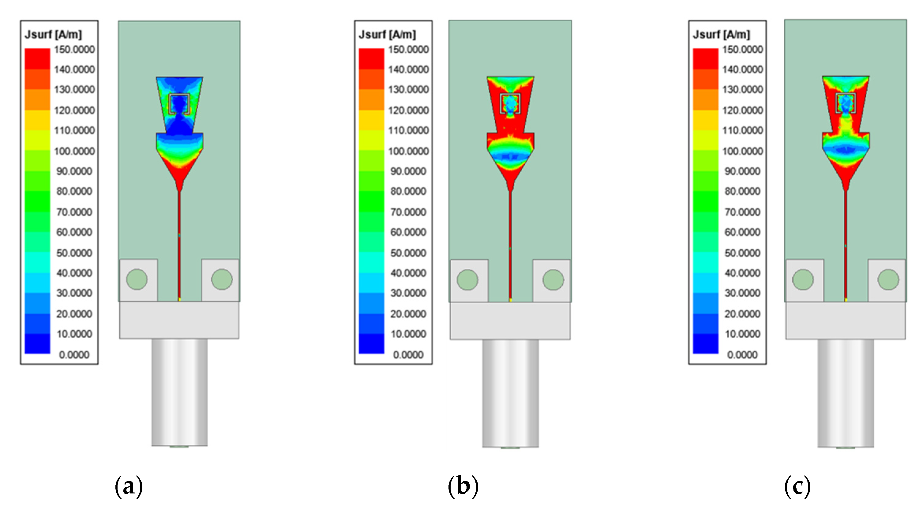
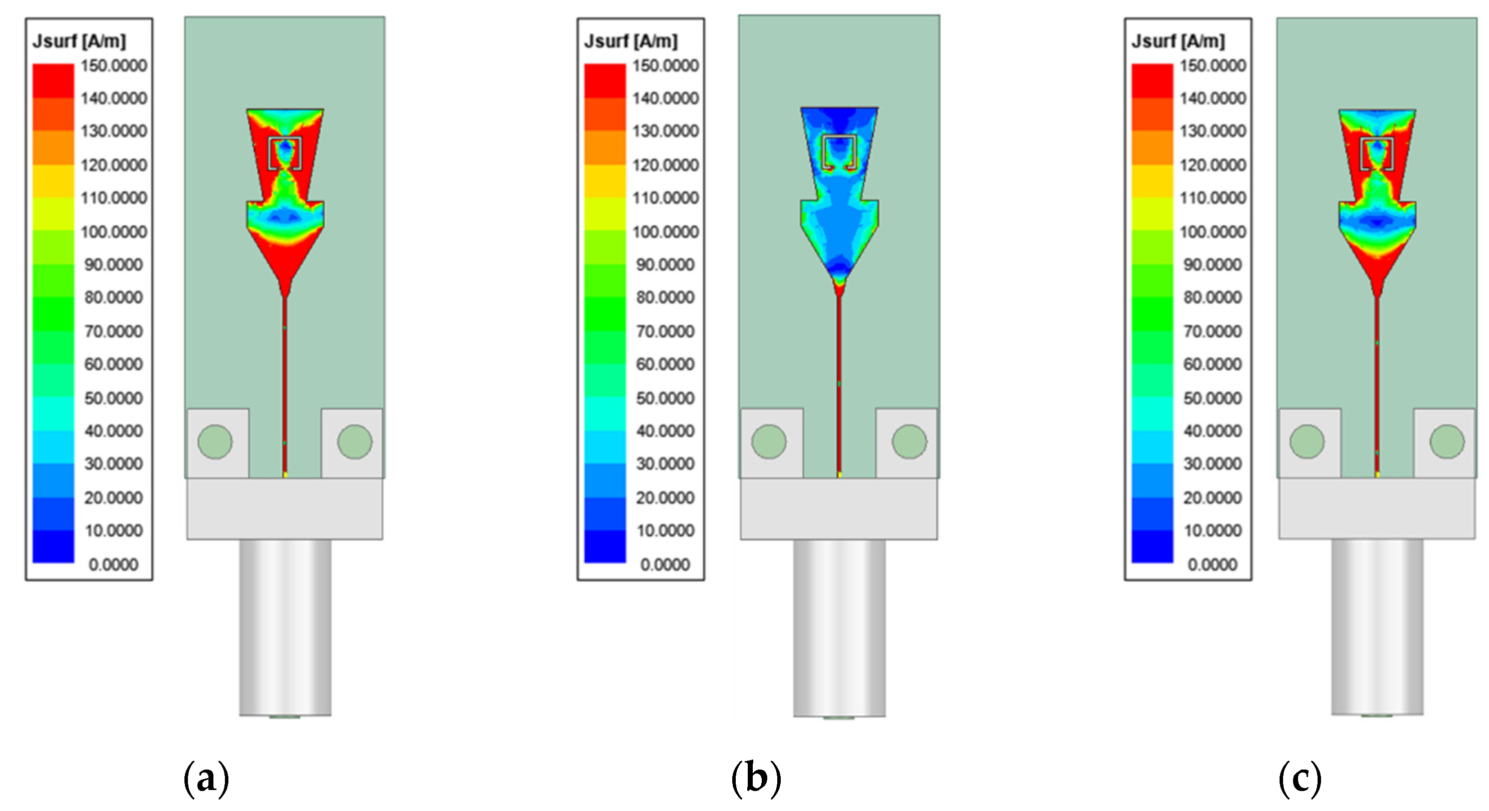
17]. Through the elliptical patch, the grounding branch, and the T-shaped branch, the surface current at the operating frequency between the patch antenna elements is effectively blocked or absorbed in this design, thereby reducing the mutual influence and achieving a broadband effect [18]. The multi-frequency effect is secured by combining two bow-tie-like curves so that the antenna can achieve resonance in different frequencies, and the extended twists and turns make the antenna operate at a lower frequency [19]. An X-band patch antenna with a coplanar waveguide (CPW) structure which can be directly connected to the antenna and transmit receiver modules without additional wiring is proposed. Therefore, when external factors are affected, unnecessary movement can be controlled and the deterioration of antenna performance can be reduced to a minimum [20]. Rectangular slot patches can also achieve impedance bandwidth by stacking cylinders with perforations and etching a rectangular slot on the ground side. The operating frequencies are combined to create a broadband hybrid dielectric resonator antenna. Alternatively, using shared aperture technology with an array design, the same aperture can be reused on dual frequency bands [21,22]. In patch antennas, slots are carved into the surface to generate resonance and shorting pins and slots are used to generate the required radiation [23]. Broadband characteristics are achieved by truncating the rectangular microstrip patch, and notch characteristics are obtained using the electromagnetic bandgap structure [24]. The coplanar waveguide structure can reduce loss. Optimizing the ground plane and the radiation patch can achieve a wide impedance bandwidth, and a patch antenna can achieve broadband [25]. A rectangular microstrip antenna and a defective ground structure (DGS) can make the antenna achieve broadband. The overall size of the antenna is 60 × 60 mm2 [26]. They use patch antennas and change the structure so that the patch is different from the traditional rectangle and the elliptical radiator design achieves the broadband effect. Dual-frequency bands for satellite communication applications can use reconfigurable circular polarization to achieve 10.8–11.8 GHz and 14–15.4 GHz, with bandwidths of 7.6% and 4.3%, respectively [27]. The whole antenna is constructed only through the substrate-integrated waveguide (SIW) and produces a mixed-mode resonance at 9.85 GHz. When the short slot is cut into the top of the cavity, dual resonances at 14 GHz are caused. The antenna measured peak gains of 6.62 dBi and 6.44 dBi at 9.85 GHz and 14 GHz, respectively [28]. These technologies can give the antenna a good connection in satellite communication.
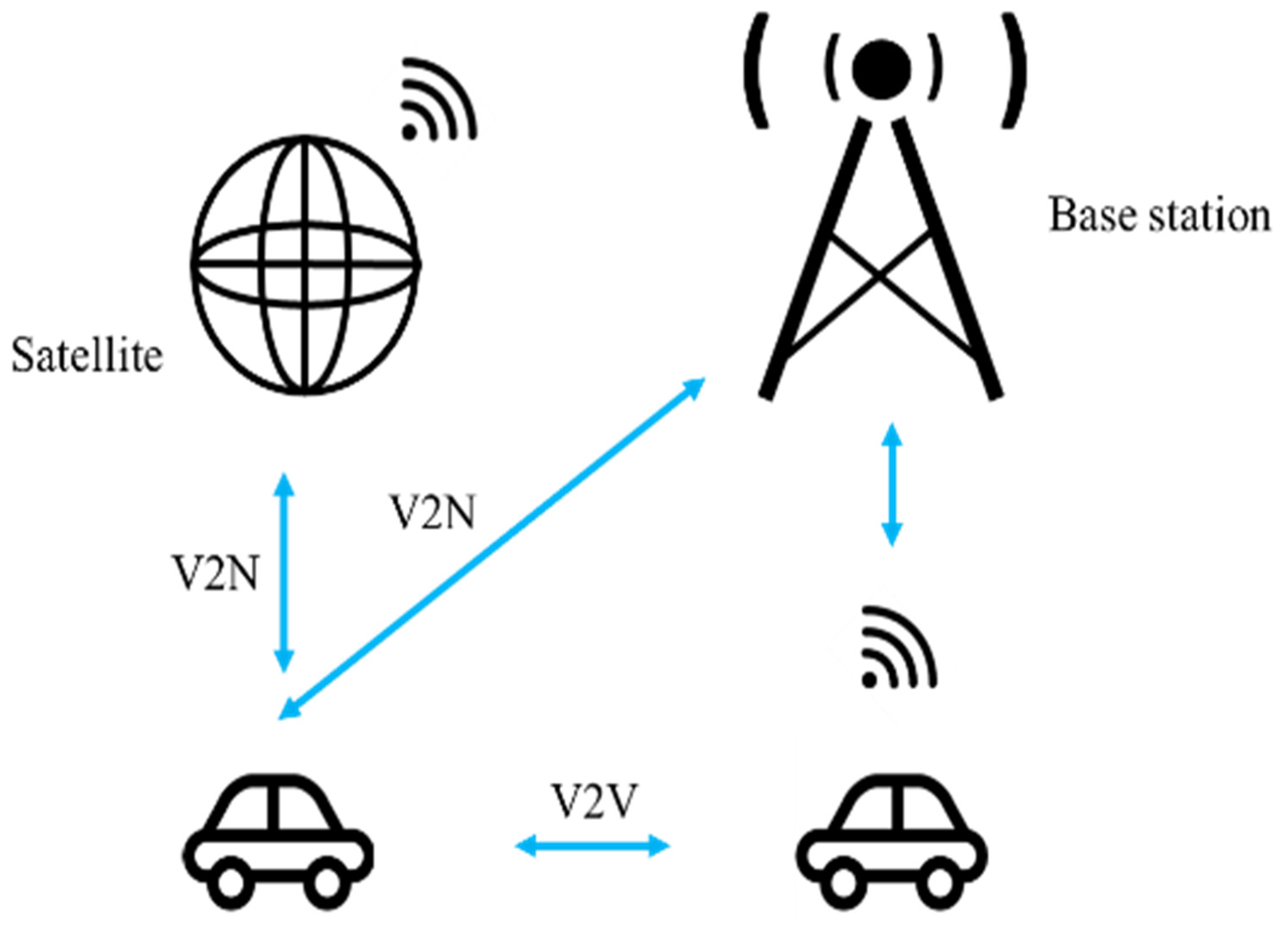
Currently, the LEO antenna uses a phased array structure to allow satellites and point-to-point communications to have better transmission quality. The antenna in this paper uses a simple structure, which makes the antenna easy to install on the vehicle and gives it a good connection with the base station, the vehicle, and LEO. Therefore, the antenna designed in this paper has the advantages of miniaturization and simple use of gradual impedance change and slotting to achieve dual-band performance to achieve Internet of vehicles applications. Therefore, to meet the requirements of multiple transmissions, the antenna in this paper uses a non-phased array structure to achieve multiple transmissions and proposes a dual-frequency antenna applied to the Internet of vehicles (IOV) system. The association diagram in the communication scene of the Internet of vehicles is shown in Figure 1.
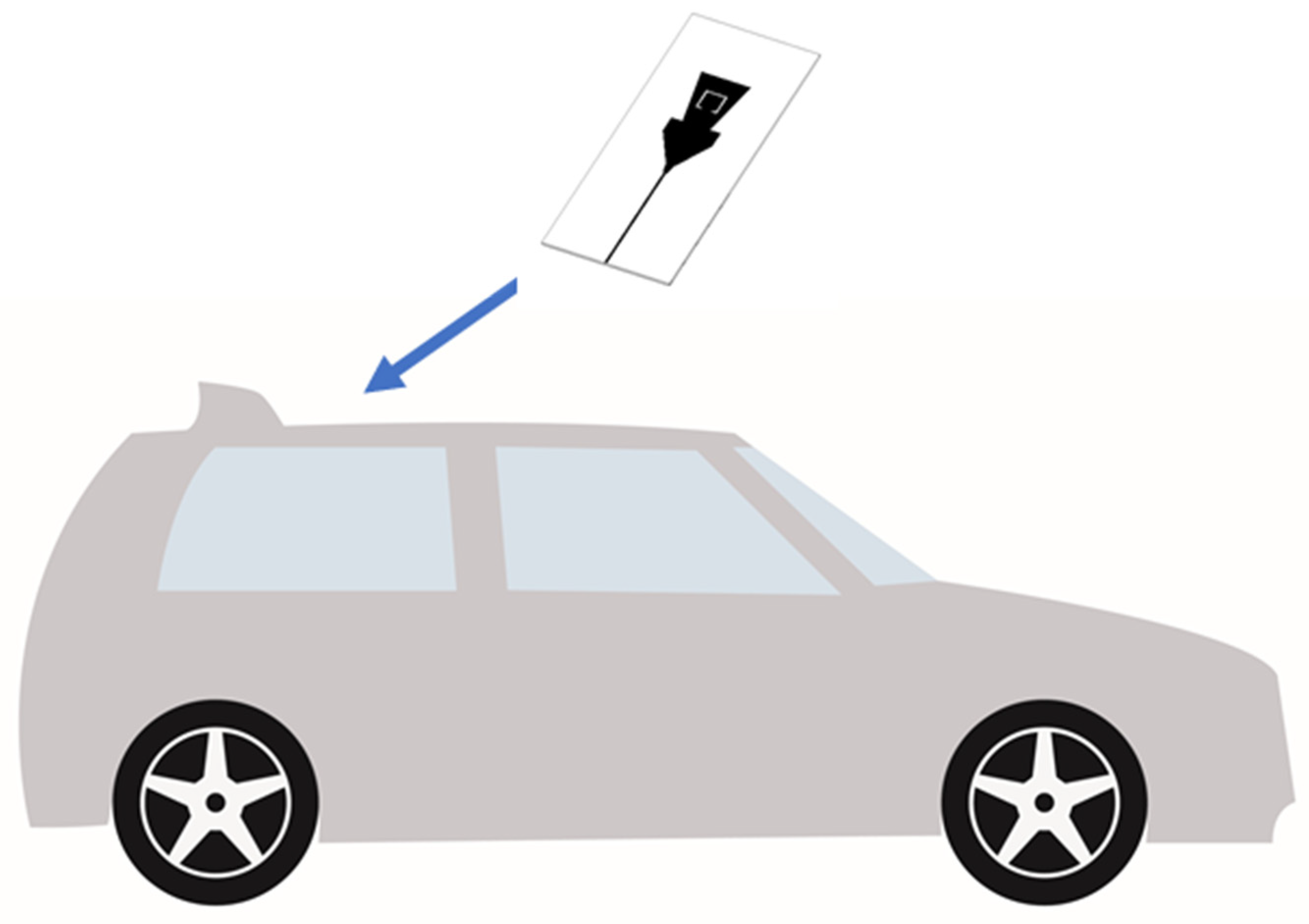
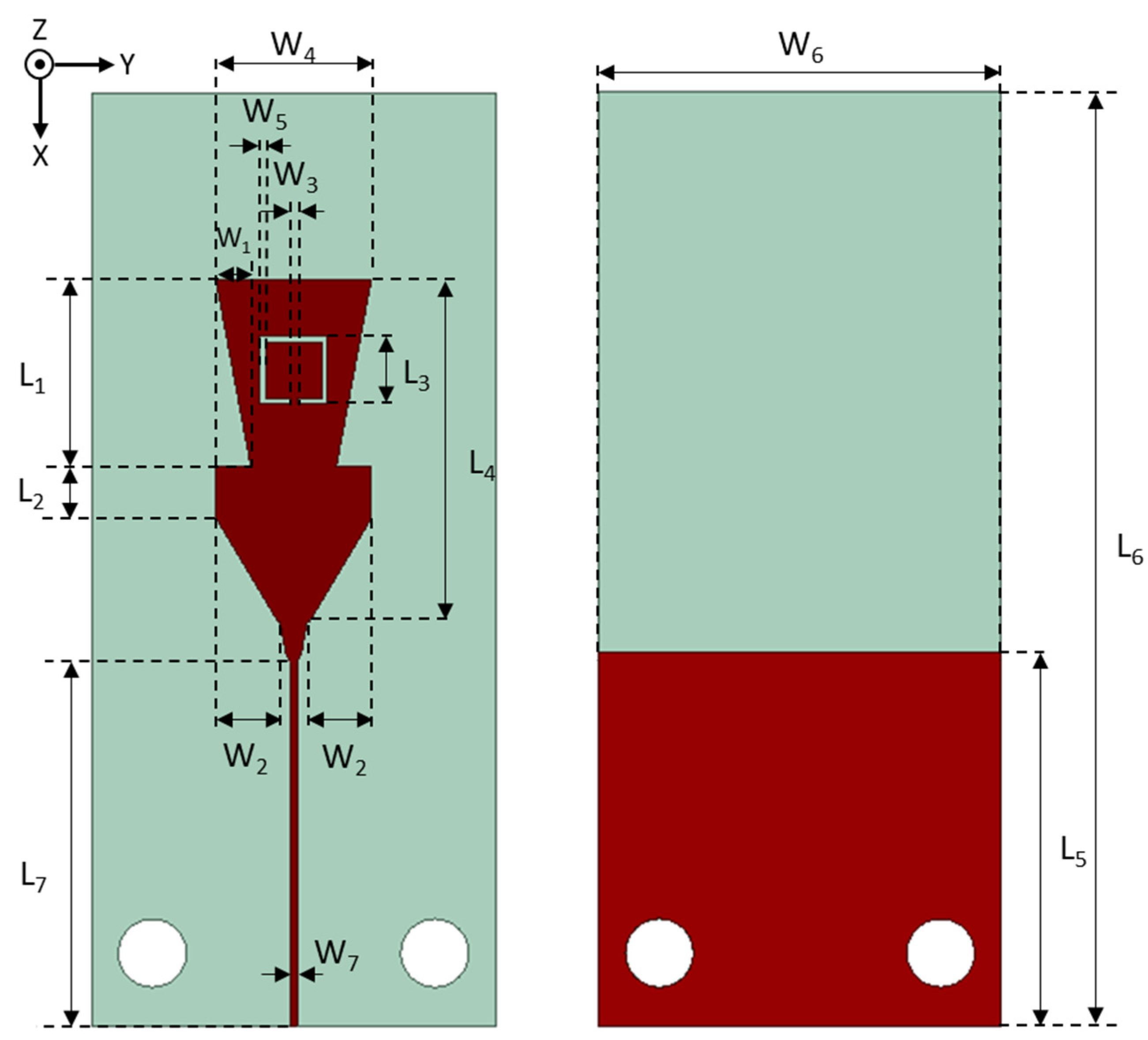
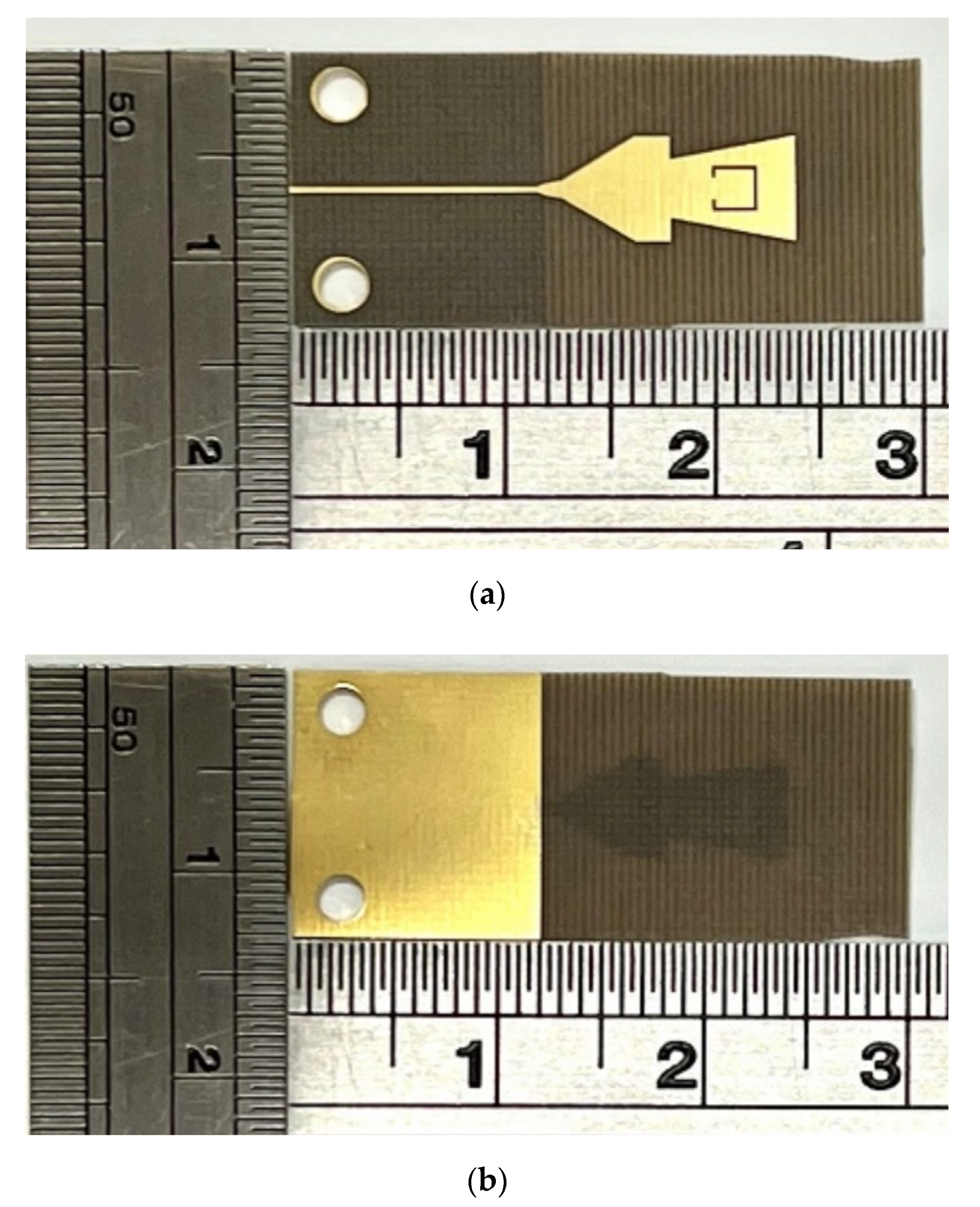
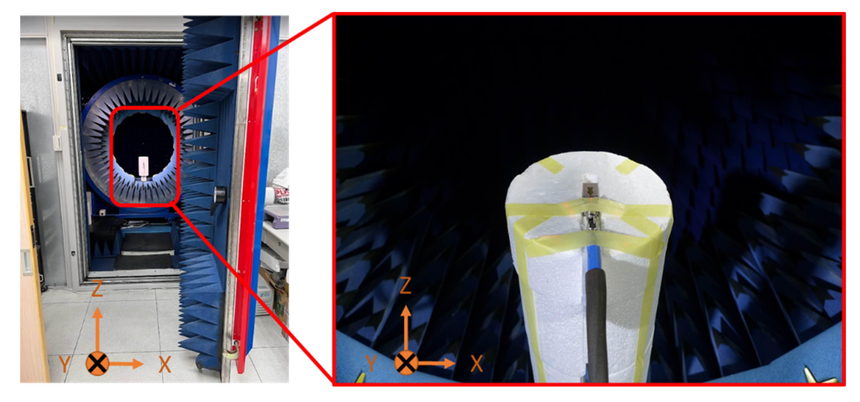
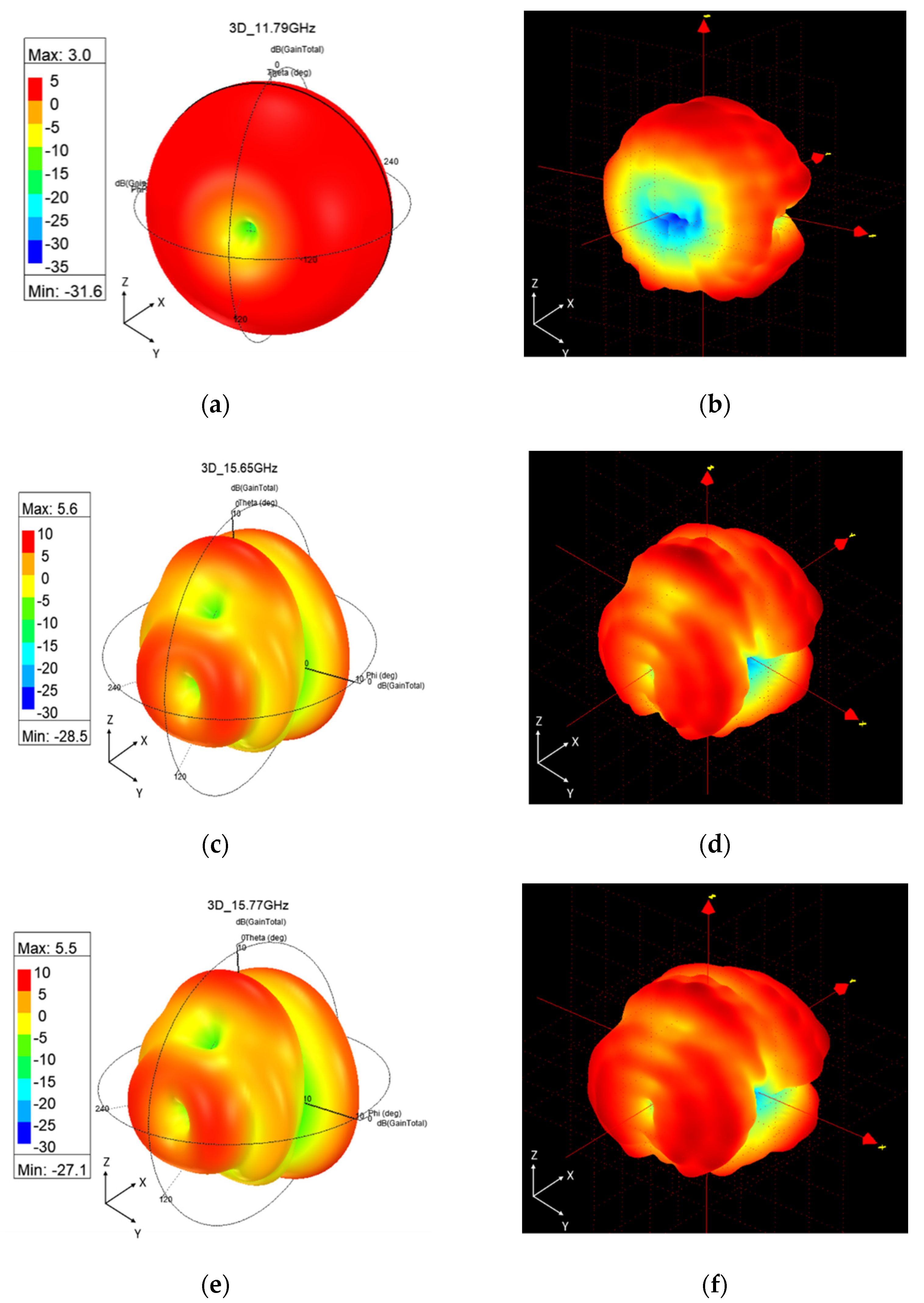
Furthermore, dual-band use is provided through the U-shaped slot in the middle of the cut triangular patch and the antenna. Moreover, the antenna performance is analyzed in the electromagnetic simulation software. The excellent performance characteristics of bandwidth, gain, and efficiency are analyzed in detail. To verify feasibility, the proposed antenna was fabricated and measured using and in the SATIMO StarLab Chamber to obtain data such as reflection coefficient, gain, radiation pattern, and efficiency. The results confirm that the proposed antenna is suitable for vehicular LEO satellite systems. The antenna designed in this paper can be installed on the roof, as shown in Figure 2.
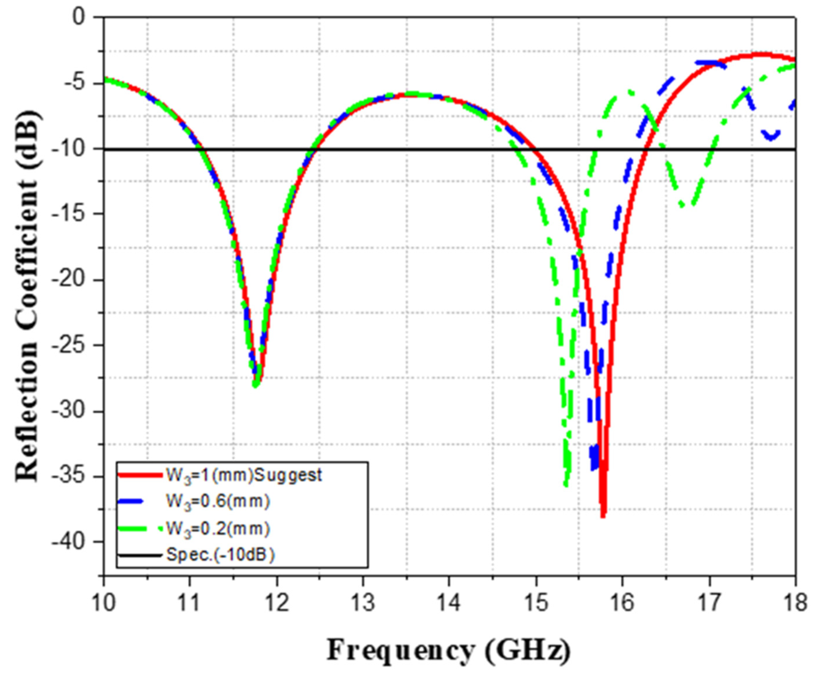
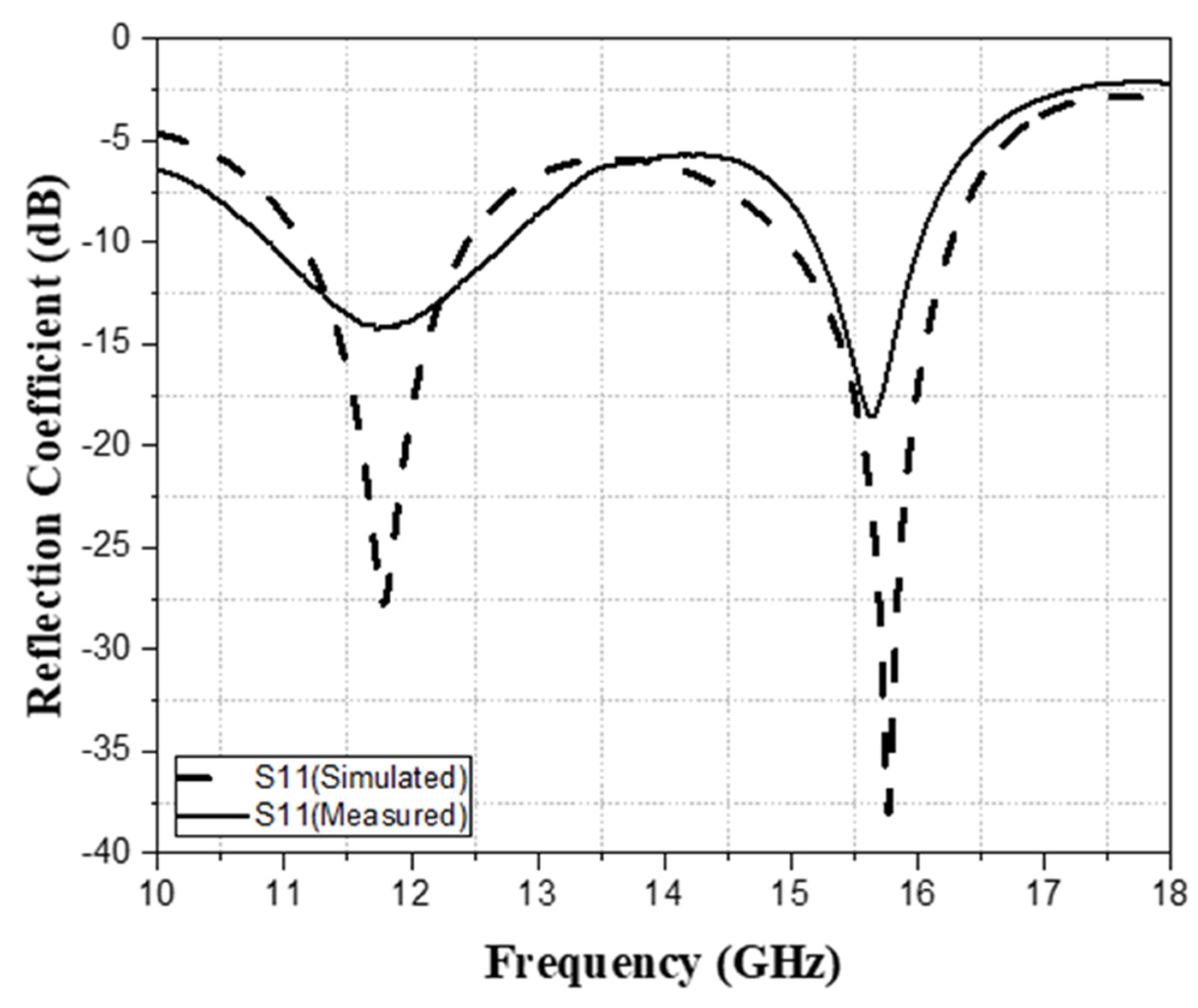
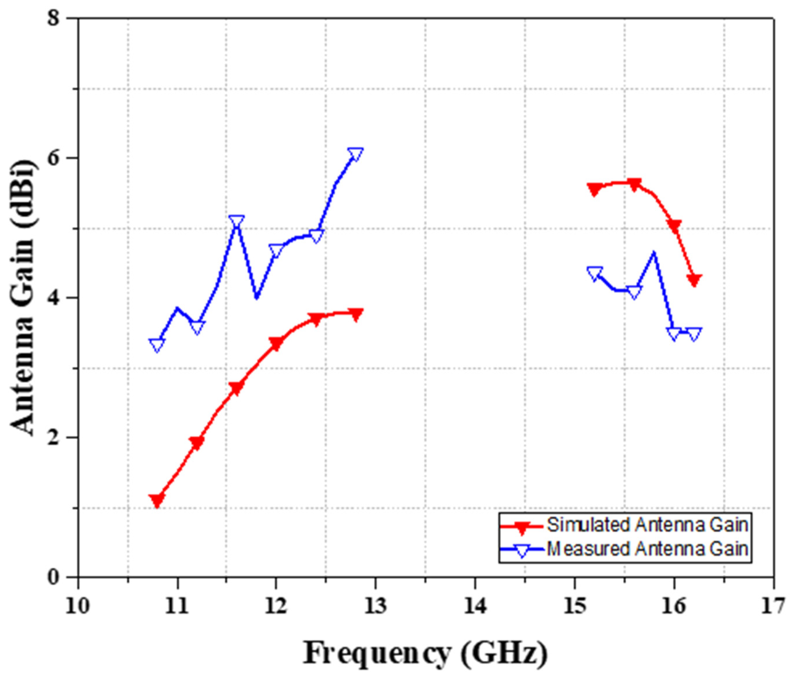
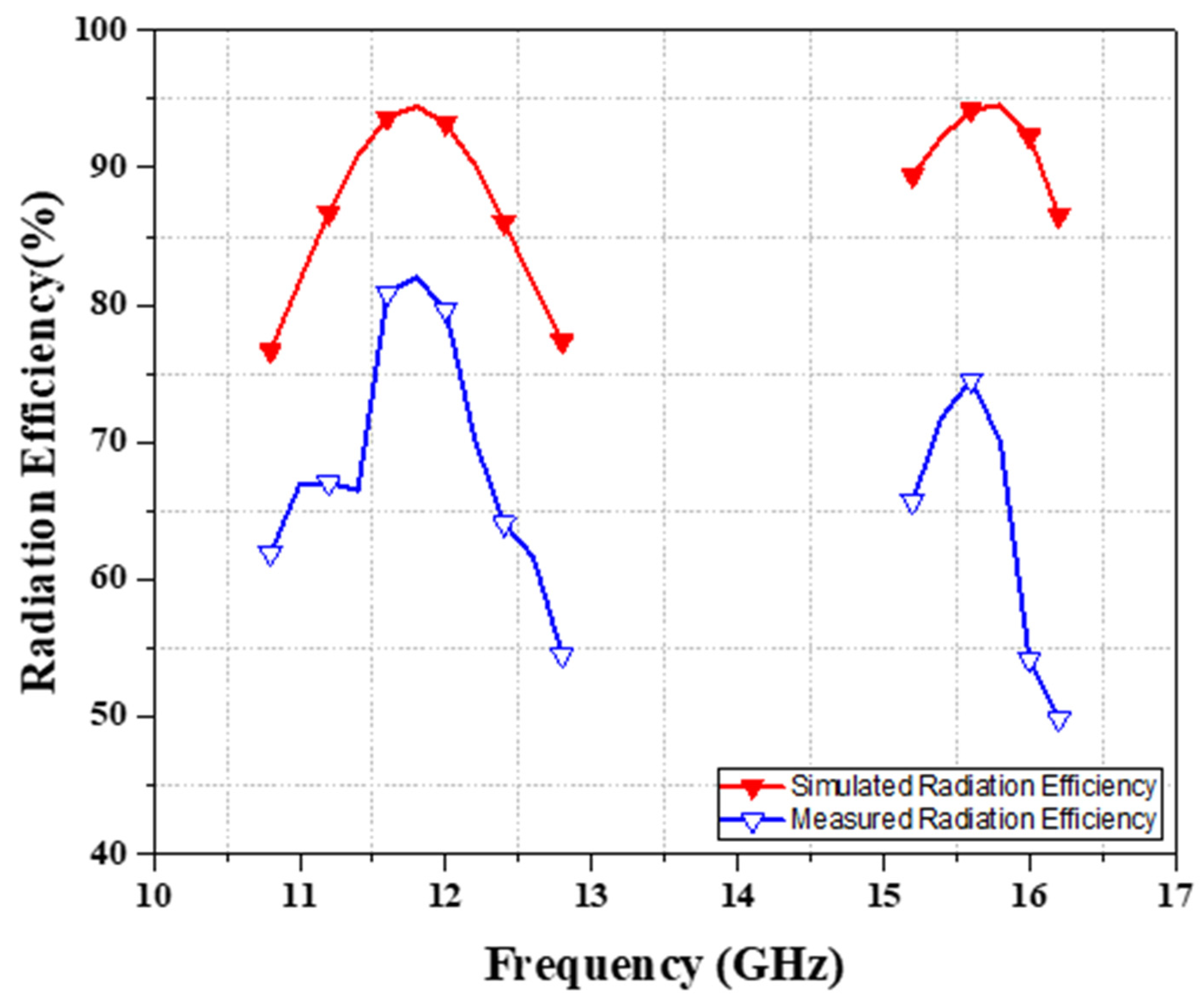
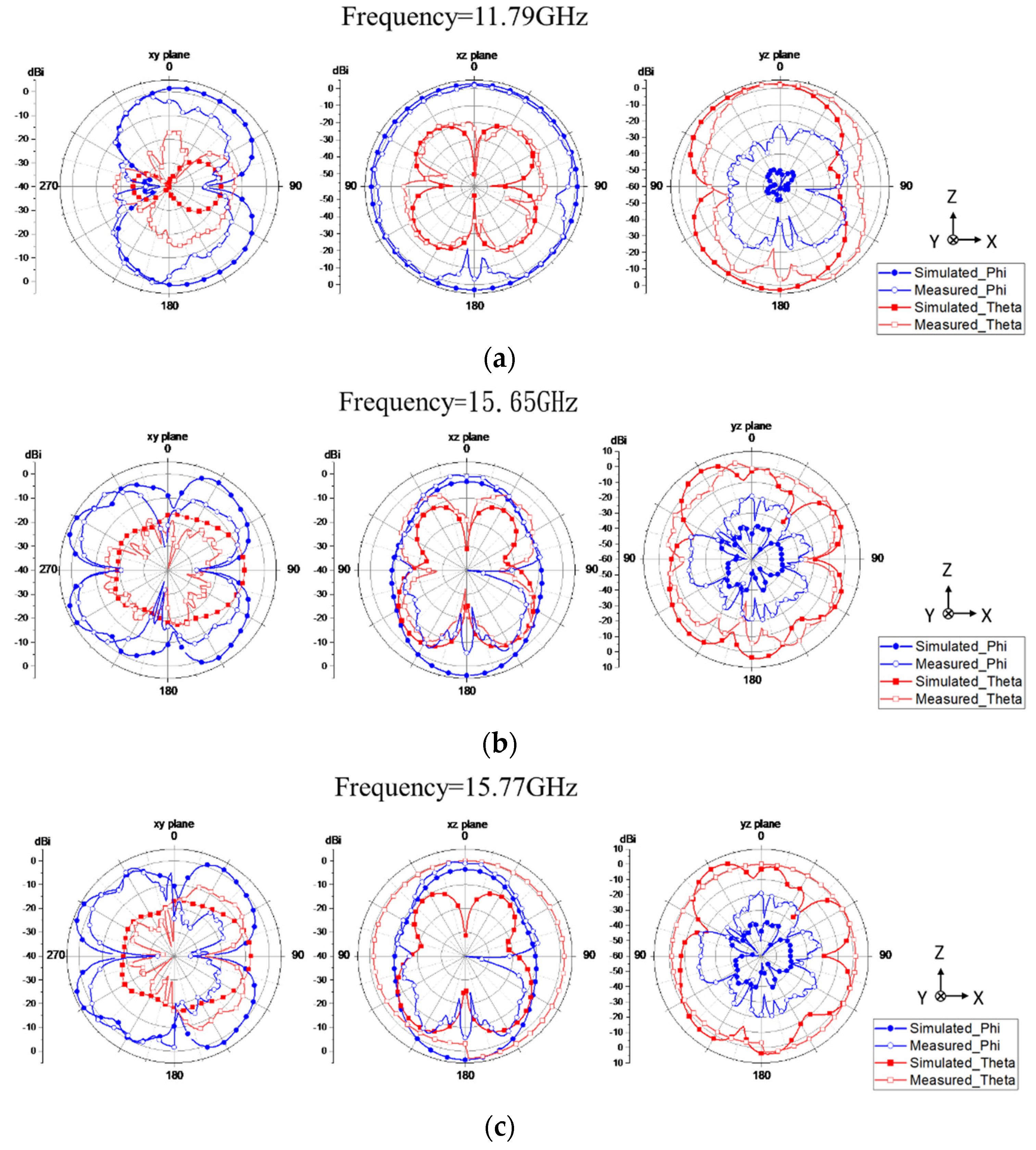
Moreover, it provided exemplary performance in the Ku band. The proposed antenna has dual-frequency bands and can cover the X band (11.13~12.45 GHz) and Ku band (14.96~16.28 GHz). The antenna efficiency is 50–80.8% and 50–74% in the X band and Ku band. In addition, the antenna gain is about 3.34–6.08 dBi and 3.50–4.65 dBi in the X band and Ku band, respectively, and the highest gain value is 6.08 dBi. This frequency band can be used for vehicle-to-satellite, IOV communication applications, and vehicle data transmission.

2. Recommended Patch Antenna Construction

2.1. Antenna Configuration

To use the antenna with the smallest antenna area in the Internet of vehicles to achieve better broadband effects, this paper designs an antenna with dual-frequency bands, high efficiency, and small dimensions, as shown in Figure 3. A feed line is set on the front of the antenna, a triangle is designed above the feed line, and an inverted-U-shaped slot is designed in the middle of the triangle so that the antenna secures the effect of dual frequency bands. Among them, the inverted-U-shaped slot enables the antenna to cover the two working frequency bands of 11.13–12.45 GHz and 14.96–16.28 GHz, and the 1.85 mm end launch connector is used for practical verification. This design is indeed suitable for low-orbit satellite X-band (10.87–12.76 GHz) and Ku-band (15.19~16.02 GHz), which can provide a good connection between the Internet of vehicles and low-orbit satellites.
This antenna is designed on Arlon DiClad 880 substrate material. The thickness of the substrate is 0.254 mm, the relative dielectric constant (εr) is 2.2, and the dielectric loss tangent (tanδ) is 0.0009. Through the inverted-U-shaped slot on the antenna, the antenna can generate two resonances to obtain dual-band characteristics, and there is no need to design two antennas to combine a single frequency band to form a dual-band operating range. This antenna design does not use multi-layer boards and can achieve dual-band operation by designing an inverted-U-shaped slot on the top of the substrate. In addition, the feed point of this antenna is connected through a simulated 1.85 mm end launch connector during simulation, which makes the antenna closer to the simulation results in practice.
The substrate area used in this article is 30 × 13 mm2, the antenna is placed on the top of the substrate, and the back of the substrate is used as a ground with an area of 12 × 13 mm2. The antenna area is 12.5 × 5 mm2. The area of the microstrip line from the feed end to the antenna is 11.6 × 0.2 mm2. The overall antenna size is shown in Figure 3 and Table 1.

2.2. Parametric Analysis

When designing this antenna, this paper analyzes the opening spacing of the inverted-U-shaped slot in the middle of the antenna body, as shown in Figure 4. The detailed dimensions and bandwidth are shown in Table 2. As shown by the green line in Figure 4, when the W1 spacing is 0.2 mm, the antenna’s dual-band bandwidths are about 1.3 GHz and 0.93 GHz when the reflection coefficient is lower than −10 dB.
The reflection coefficient is shown in the following equation:
Reflection   Coefficient   dB = 10 × log 10 ( P R P I ) ,  
where PR is power reflected (W) and PI is power incident (W).
As the spacing of the W3 openings increases to 0.6 mm, the blue line in Figure 4 can be observed. The bandwidth of the low-frequency band is increased to 1.32 GHz, and the improvement is more obvious in the high-frequency band, which can be increased to 1.22 GHz. For the red line in Figure 4, when the W3 spacing is 1 mm, the low-frequency and high-frequency bandwidths with reflection coefficients lower than −10 dB are 1.32 GHz and 1.3 GHz, respectively. It can be clearly seen that changing the spacing parameters of the openings makes the current path switch, thereby increasing the bandwidth used in dual-frequency bands. When the spacing of W3 is 1 mm, it is the largest bandwidth, so the spacing of W3 is selected as 1 mm.
Next, the length L2 of the inverted triangle below the antenna body is analyzed, as shown in Figure 5. The detailed dimensions and bandwidth are shown in Table 3. When the length of L2 is 3 mm, the green line in Figure 5 can be observed, and the dual-band reflection coefficients are about 1.25 GHz and 1.32 GHz when the reflection coefficient is lower than −10 dB. When the length L2 is shortened to 2.3 mm, the blue line in Figure 5 can be observed and the bandwidth of the low-frequency band is increased, but the bandwidth of the high-frequency band will be reduced accordingly, and the dual bandwidths are about 1.3 GHz and 1.24 GHz, respectively. Therefore, when we analyze the shortening of the length L2 to 1.6 mm, the reflection coefficient is represented by the red line in Figure 5, in which the bandwidths of the low-frequency and high-frequency bands are 1.32 GHz and 1.3 GHz, respectively, and the low-frequency and high-frequency bandwidths are almost the same, making the antenna more average in the operating frequency band. It can be observed that the application bandwidths of the dual band are affected by the change of the area of the antenna radiation patch. In order to make the antenna more average in the working frequency band, 1.6 mm is selected for the length L2.
Parameter analysis on the ground plane area of this antenna was then performed, as shown in Figure 6. The detailed dimensions and bandwidth are shown in Table 4. When the length of L5 is 10 mm, the green line in Figure 6 can be observed as a slight resonance, but the resonance is not apparent. When the L5 length is changed to 11 mm, the blue line in Figure 6 indicates that the dual bands are about 0.85 GHz and 0.86 GHz when the reflection coefficient is lower than −10 dB. Finally, when the L5 length is analyzed to 12 mm, the red line in Figure 6 can be obtained when the reflection coefficient is lower than −10 dB and the dual bandwidths are 1.32 GHz and 1.3 GHz. It can be seen that the area of the ground plane can affect the resonance of the antenna, making the resonance more obvious. When the length of L5 is 12 mm, the bandwidth distribution is more even. Therefore, this paper chooses the length L5 of the grounding area to be 12 mm.
This paper shows the parametric analysis of the triangular chamfer below the antenna body, as shown in Figure 7a,b. First, when the antenna presents a rectangular shape without any change, the applicable frequencies of Type 1 dual band are 10.44–11.49 GHz and 15.64–16.71 GHz. The bandwidths are about 1.05 GHz and 1.07 GHz, respectively, when the reflection coefficient is lower than −10 dB. To improve the application bandwidth, a triangle with a length of 1.6 mm and a width of 1 mm is cut at the right-angle positions of the lower-left and lower-right of the antenna, which is a symmetrical structure. The total excision area is 0.8 mm2. The results show that the applicable frequencies of Type 2 dual band are 10.67–11.8 GHz and 15.37–16.54 GHz. The bandwidths increase by 0.08 GHz and 0.1 GHz, respectively, when the reflection coefficient is lower than −10 dB.
In order to make the applicable frequency bandwidth wider, the area of the oblique triangle is enlarged at the symmetrical right-angle positions at the lower left and lower right of the antenna—the chamfered triangle with a length of 3.3 mm and a width of 2 mm. The total excision area was 3.3 mm2. Compared with Type 2, the length and width of resection increased by 1.7 mm and 1 mm, respectively, and the total resection area increased by 2.5 mm2. At this time, the bandwidths of Type 3 are 11.13–12.45 GHz and 14.96–16.28 GHz. The bandwidths increase by 0.19 GHz and 0.15 GHz, respectively, when the reflection coefficient is lower than −10 dB. The impedance matching is transformed into a gradual type by increasing and decreasing the area, so the improvement of the overall matching can increase the bandwidth of the two applications by 0.27 GHz and 0.25 GHz, respectively.
This paper uses a parametric analysis of the triangular chamfer above the antenna body, as shown in Figure 8a,b. First, when there is a rectangular shape and an oblique cut above the antenna, the applicable frequency band of Type 1 is 14.09–15.06 GHz. The bandwidth is 0.97 GHz under the standard of reflection coefficient below −10 dB. In order to give the antenna dual-band operation, the right-angled triangles are progressively removed at the upper-left and upper-right corners of the antenna. The triangles had lengths of 2 mm and widths of 0.38 mm. The total excision area was 0.38 mm2. Currently, the applicable frequencies of Type 2 dual band are 11.27–12.34 GHz and 14.98–16.08 GHz. It can be seen that the antenna has one more frequency band at 11.8 GHz. The bandwidths are 1.07 GHz and 1.1 GHz, respectively, when the reflection coefficient is lower than −10 dB.
Next, the area of the oblique cut triangle is increased to a length of 3.3 mm and a width of 2 mm. The total excision area was 3.3 mm2. Compared to Type 2, the length and width of resection increased by 1.3 mm and 1.62 mm, respectively and the total resection area increased by 1.053 mm2. The bandwidths of Type 3 are 11.13–12.45 GHz and 14.96–16.28 GHz. The bandwidth increases by 0.25 GHz and 0.22 GHz, respectively, when the reflection coefficient is lower than −10 dB. It can be observed that the asymptotic impedance matching allows the current path to be switched, and the overall matching improvement can produce an application frequency band and increase the overall bandwidth.

2.3. Surface Current

In Figure 9a–c, the current distribution is used to explain the effect of the inverted-U-shaped slot of the antenna on dual-band operation. The excitation position of the antenna frequency band can be observed through the current distribution. Firstly, the surface current distribution in the low-frequency band 11.13–12.45 GHz is analyzed. The operating mode of this antenna is to enter from the feed point of the 1.85 mm end launch connector, and the current will be distributed from the feed line to the surrounding of the inverted-U-shaped slot. Figure 9b shows the current distribution at 12.45 GHz. It can be seen that the current enters the bottom of the patch antenna from the feed line, and a strong electric field can be seen around the oblique triangle and the inverted-U-shaped slot. The current is changed through the slot path, resulting in frequency band resonance. Figure 9c shows that at the lowest resonance point of 11.79 GHz, the current is distributed around the triangular chamfered corner and the inverted-U-shaped slot resonates with the slot and the frequency band.
In Figure 10a–c, the surface current distribution is analyzed in the high-frequency band 14.97–16.27 GHz. Figure 10a shows the current distribution at 14.97 GHz. The current is distributed around the U-shaped slot from the feed line, the maximum current excitation is generated through the obliquely cut triangle and the slot, and the required frequency band resonance is achieved. Figure 10b shows the current distribution at 16.27 GHz, and the current at this frequency is distributed around the inverted-U-shaped slot. In Figure 10c, it can be observed that at the lowest resonance point, 15.77 GHz, the current is distributed around the inverted-U-shaped slot on both sides of the oblique triangle, and it can be observed that resonance occurs. The high-frequency current has a more robust current flow inside the inverted-U-shaped slot than the low frequency.

3. Results

3.1. S-Parameters Analysis

Figure 11a,b show this paper’s dimensions of the dual-band antenna. The model of the network analyzer used this time was Agilent N5227A, and the measurement range was 10 MHz–67 GHz. The coaxial cable used the model (WCA205–1.2 M-65 GHz), the length was 120 cm, and the maximum frequency was up to 65 GHz. OSL (open circuit, short circuit, load load) was used for calibration before measurement. It can be seen that the simulated and measured bandwidth results of the dual-band low-orbit satellite patch antenna are quite consistent, but the measured resonant frequency points are inconsistent with the simulated results, which is presumably caused by the connector or placement. Under the standard of −10 dB reflection coefficient during simulation, the dual working simulation frequency bands are 11.13–12.45 GHz and 14.96–16.28 GHz. The analog application frequency band’s lowest resonance point at 11.13–12.45 GHz reaches −27.5 dB at 11.79 GHz. In the working frequency band 14.96–16.28 GHz, the lowest resonance point reaches −41.26 dB at 15.77 GHz. Measurements were obtained using an Agilent N5227A. Under the standard of −10 dB reflection coefficient, the measurement operating frequency bands are 10.87–12.76 GHz and 15.19–16.02 GHz, as shown in Figure 12. It shows that the low-frequency measurement reaches −14.2 dB at the lowest resonance point at 11.8 GHz, and the bandwidth increased by 0.57 GHz compared to the simulation results. On the other hand, the high-frequency band reaches −18.4 dB at the lowest resonance point at 15.66 GHz, and the bandwidth is reduced by 0.49 GHz compared to the simulation results. Although the bandwidth of the lower frequency band is reduced, the simulation and measurement trends of the upper and lower frequency bands are generally consistent.

3.2. Gain and Efficiency of Patch Antenna

The proposed antenna was measured using the SATIMO StarLab Chamber antenna measurement near-field darkroom system from French MVG Group (Microwave Vision Group), which can provide applications for various communication products such as mobile phones, computers, tablets, automobiles, etc. The system provides measurement capabilities such as gain/directivity, 3D radiation pattern, and efficiency. The network analyzer model is American Agilent N5230A, and the measurement frequency band of the standard antenna in the darkroom is 0.8–18 GHz. Figure 13 shows the antenna’s measured environment in the darkroom, which is erected with the simulated software’s xyz axis corresponding to the darkroom’s xyz axis.
The simulated and measured gain of this antenna are shown in Figure 14. The gain of an antenna is directivity multiplied by radiation efficiency. The gain of an antenna is shown in the following equation:
G dB = 10 log 10 ( 4 π η A λ 2 ) ,  
among them, GdB is the antenna gain, η is the efficiency, A is the physical aperture area, and λ is the wavelength of the signal.
The simulated antenna gain is about 1.78–3.74 dBi in the low-frequency X band (11.13–12.45 GHz) and about 3.99–5.65 dBi in the high-frequency Ku band (14.96–16.28 GHz). The dual-band analog peak gain is 5.65 dBi. The measured antenna gain is 3.04–6.08 dBi in the low-frequency X band (10.87–12.76 GHz) and 3.50–4.65 dBi in the high-frequency Ku band (15.19–16.02 GHz). The measured antenna peak gain is 6.08 dBi.
The simulated and measured efficiency of this antenna are shown in Figure 15. Antenna efficiency is the ratio of total external radiated power to input power. That is, the relative ability of an antenna to convert a transmitter’s radio frequency energy into electromagnetic waves expressed as a percentage and depending on frequency. For example, the radiation efficiency of an antenna is shown in the following equation:
Radiation   Efficiency = Gain Directivity × 100 % .  
The simulated antenna efficiency is about 85–94% in the low-frequency X band (10.87–12.76 GHz) and about 85–94% in the high-frequency Ku band (15.19–16.02 GHz), and the simulated peak efficiency is 94.5%. The measured antenna efficiency is 50–80.8% in the low-frequency X band (10.87–12.76 GHz), and the highest measured antenna efficiency in the high-frequency Ku band 50–74% is 80.8% at the frequency point 11.6 GHz. The antenna efficiency measurement results are generally lower, but the overall trend is similar. The radiation efficiency of the patch antenna simulations is in good agreement with the measured results.

3.3. Radiation Pattern

Figure 16a–f show the 3D field pattern simulated and measured radiation pattern. Because the strength of the electric field and magnetic field generated in each direction is different, and the performance of the field strength varies with the angle, in order to find out where the overall radiation field of the antenna is the strongest, the 3D mode can be used to observe the radiation field. Figure 16a,b show the simulated and measured radiation patterns at 11.79 GHz. It shows that the radiation patterns are very uniformly distributed around the antenna. In Figure 16c,d, the simulated and measured radiation patterns at 15.65 GHz are shown, and the radiation patterns are concentrated above the antenna. Figure 16e,f are the simulated and measured radiation pattern at 15.77 GHz, and the radiation pattern is also concentrated above the antenna. Through the measurement of the antenna, after comparing it with the simulation diagram, the trends of the two are in good agreement. At the three frequency points—11.79 GHz, 15.65 GHz, and 15.77 GHz—it can be seen that the X band (11.13–12.45 GHz) and the Ku band (14.97~16.27 GHz) radiate more above the antenna as a whole. Therefore, if the antenna is installed in the upper part of the vehicle roof, it can achieve good communication transmission with the base station.
Table 5 and Figure 17 show the 2D simulated and measured radiation patterns for 11.79 GHz, 15.65 GHz, and 15.77 GHz. In order to facilitate the discussion of the field diagram, after the 3D field diagram is planarized, the field patterns of three different planes—xy, xz, and yz—can be analyzed through the 2D field pattern, and the antenna radiation direction and the strongest radiation position can be clearly known. Figure 17a shows the frequency point 11.79 GHz plane radiation pattern simulation and measurement; the xy plane and theta plane measurement results are compared with the simulated overlay, and it can be seen that the gain measurement results are measured at the angle of 40 degrees; 135 degrees is small, and the other angles are similar to the simulation results. On the phi plane, the overall gain of the measurement result is higher, and the field pattern is not similar to the simulation. Only at 90 degrees and 270 degrees is the measured field trend similar to the simulation. The measurement results of the xz radiation plane in the phi and theta planes are quite consistent with the simulation results. Finally, the overall field pattern of the theta surface measured on the yz plane is similar to the 0-degree position, and the overall radiation pattern is close to the simulation result. In contrast, the phi plane measurement result has a higher radiation pattern gain, and the simulation overall is lower than the radiation gain. The theta plane of xy and the phi radiation surface of yz are not similar to the simulation and measurement results, which may be caused by the connector effect and placement.
Next, comparing the antenna radiation pattern simulation and measurement results shows the plane radiation pattern simulation and measurement of the frequency point at 15.65 GHz, as shown in Figure 17b. Comparing the measurement results of the xy plane and the theta plane with the simulated overlay, it can be seen that the measurement field gain is small at an angle of 90 degrees, and the rest of the angles are similar to the simulation results. Likewise, the phi plane simulation and measurement results are very similar except that the measurement field gains are lower at 45 degrees and 135 degrees and that there is a tendency to shrink inward.
Compared to the simulation results, the field pattern of the xz radiation surface at the 180-degree position of the measured phi plane has a lower gain, and the simulation results are quite consistent after the theta surface measurement results are compared. Finally, the overall field pattern of the theta plane measured on the yz plane is higher than the uniform simulation result. The radiation pattern gain of the phi plane measurement result is higher, but the simulation result is lower. The above yz radiation surface simulation and measurement results are not similar, which may be caused by the connector effect. Figure 17c shows the simulation and measurement of the planar radiation pattern at the frequency point of 15.77 GHz. Comparing the measurement results of the xy plane and the theta plane to the simulated overlay, it can be seen that the measurement results have higher field gain at angles of 45 degrees and 135 degrees, respectively, and the rest of the angles are similar to the simulation results. After comparing the xz plane and the phi plane, it can be observed that the overall measurement gain is higher. The xz radiation surface has a higher overall gain in the measured theta surface compared to the simulation results. However, the overall trend of the phi surface is similar to the simulation results. After comparing the measurement results of the yz plane and the theta plane, the simulation results are pretty consistent. Compared with the phi plane, the field-type gain is higher at 0 degrees and 90 degrees.

3.4. Performance Comparison with Other Antennas

The antenna designed in this paper is also compared to recent literature and presented in Table 6, which lists the frequency band, bandwidth, gain, efficiency, and dimensions. The size of the antenna designed in this paper is 30 × 13 × 0.254 mm3. In [17,18,21,23,24,25,26,27], the minimum area size is [23], and its area is 22.46 × 21.95 mm2, the same as this paper. Compared to the antenna, the area gap is 102.9 mm2, which gives the antenna designed in this paper an advantage in small-scale in-vehicle applications.
The bandwidth percentage of the antenna in this paper is 15.99% in the X band (10.87–12.76 GHz) and 5.31% in the Ku band (15.19–16.02 GHz). Therefore, compared to [20,23,27], it has a higher frequency bandwidth percentage, which gives the antenna a more comprehensive application frequency range.
Our proposed antenna design gain values are 3.34–6.08 dBi in the X band (11.13–12.45 GHz) and 3.50–4.65 dBi in the Ku band (14.97–16.27 GHz). Although the directivity is not high, the measured peak efficiency of the antenna in this paper is 80.8%. The reference [17] has a large bandwidth, but the antenna’s efficiency is low. It may cause a bad effect when the antenna is used by a moving vehicle and cannot receive good information from the base station. The antenna proposed in this paper has dual operating frequency bands, high efficiency, and small size and is suitable for low-orbit satellite systems in the Internet of vehicles.

4. Conclusions

This paper proposes an antenna with a simple structure and small size, which can provide dual-band characteristics in the low-orbit satellite system in the Internet of vehicles system and has the advantages of simple manufacturing and a small area. The working frequency can cover the X band (10.87–12.76 GHz) and Ku band (15.19–16.02 GHz) under the reflection coefficient of −10 dB. It can cover dual frequency bands, and the bandwidth of the X band is 15.99% and that of the Ku band is 5.31%, with a wide range of applicable frequency bands.
In this paper, the antenna was successfully fabricated, and the measured antenna data were verified to be in good agreement with the simulation results. The antenna efficiencies are about 50–80.8% and 50–74% in the low-frequency and high-frequency bands, respectively, but compared to other references in Table 6, if the overall average efficiency can be further improved, the antenna will have better transmission quality. Because high antenna efficiency gives the antenna good performance in moving vehicles. The antenna designed in this paper realizes dual-band and small-dimension features in self-driving cars and Internet of vehicles communication system equipment. In the future, this antenna can be added to the MIMO design and further use other frequency bands. Achieving the smallest area possible is the priority so that the antenna can achieve good wireless transmission capabilities between vehicles and satellites/infrastructure in the Internet of vehicles system.

Author Contributions

Conceptualization, M.-A.C.; methodology, M.-A.C.; software, M.-A.C. and I.-P.M.; validation, I.-P.M. and K.-C.T.; formal analysis, M.-A.C., I.-P.M., and K.-C.T.; investigation, M.-A.C.; resources, M.-A.C.; writing—original draft preparation, M.-A.C. and I.-P.M.; writing—review and editing, M.-A.C.; visualization, M.-A.C.; supervision, M.-A.C.; project administration, M.-A.C.; funding acquisition, M.-A.C.; All authors have read and agreed to the published version of the manuscript.

Funding

This research received no external funding.

Conflicts of Interest

The authors declare no conflict of interest.

References

  1. Khalifa, M.O.; Yacoub, A.M.; Aloi, D.N. A multiwideband compact antenna design for vehicular sub-6 GHz 5G wireless systems. IEEE Trans. Antennas Propag. 2021, 69, 8136–8142. [Google Scholar] [CrossRef]
  2. Kannappan, L.; Palaniswamy, S.K.; Wang, L.; Kanagasabai, M.; Kumar, S.; Alsath, M.G.N.; Rao, T.R. Quad-port multiservice diversity antenna for automotive applications. Sensors 2021, 21, 8238. [Google Scholar] [CrossRef] [PubMed]
  3. Zhang, L.; Zhang, J.; He, Y.; Mao, C.; Li, W.; Wong, S.-W.; Mei, P.; Gao, S. A Single-Layer 10–30 GHz Reflectarray Antenna for the Internet of Vehicles. IEEE Trans. Veh. Technol. 2021, 71, 1480–1490. [Google Scholar] [CrossRef]
  4. Wang, R.; Ma, J.-J.; Chen, C.-S.; Wang, B.-Z.; Xiong, J. Low-profile implementation of U-shaped power quasi-isotropic antennas for intra-vehicle wireless communications. IEEE Access 2020, 8, 48557–48565. [Google Scholar] [CrossRef]
  5. Michel, A.; Singh, R.K.; Nepa, P. A Compact and Wideband Dashboard Antenna for Vehicular LTE/5G Wireless Communications. Electronics 2022, 11, 1923. [Google Scholar] [CrossRef]
  6. Yang, P.; Yang, R.; Li, Y. Dual circularly polarized split beam generation by a metasurface sandwich-based Fabry–Pérot resonator antenna in Ku-band. IEEE Antennas Wirel. Propag. Lett. 2021, 20, 933–937. [Google Scholar] [CrossRef]
  7. Wang, W.; Zheng, Y. Wideband gain enhancement of a dual-polarized MIMO vehicular antenna. IEEE Trans. Veh. Technol. 2021, 70, 7897–7907. [Google Scholar] [CrossRef]
  8. Pirapaharan, K.; Ajithkumar, N.; Sarujan, K.; Fernando, X.; Hoole, P.R. Smart, Fast, and Low Memory Beam-Steering Antenna Configurations for 5G and Future Wireless Systems. Electronics 2022, 11, 2658. [Google Scholar] [CrossRef]
  9. Kraus, D.; Diwold, K.; Pestana, J.; Priller, P.; Leitgeb, E. Towards a Recommender System for In-Vehicle Antenna Placement in Harsh Propagation Environments. Sensors 2022, 22, 6339. [Google Scholar] [CrossRef]
  10. Bryant, B.; Won, H.; Hong, Y.-K.; Lee, W.; Choi, M. Design of Triple-Band (DSRC, 5G, 6G) Antenna for Autonomous Vehicle Telematics. Electronics 2022, 11, 2523. [Google Scholar] [CrossRef]
  11. Im, C.; Lim, T.-H.; Jang, D.; Kong, N.-K.; Choo, H. Design of a Printed 5G Monopole Antenna on Vehicle Window Glass Using Parasitic Elements and a Lattice-Structure Reflector for Gain Enhancement. Appl. Sci. 2021, 11, 9953. [Google Scholar] [CrossRef]
  12. Kumar, R.; Arnon, S. SNR Optimization for LEO Satellite at sub-THz Frequencies. IEEE Trans. Antennas Propag. 2022, 70, 4449–4458. [Google Scholar] [CrossRef]
  13. Chung, M.-A.; Yang, C.-W. Miniaturized broadband-multiband planar monopole antenna in autonomous vehicles communication system device. Electronics 2021, 10, 2715. [Google Scholar] [CrossRef]
  14. Chung, M.-A.; Yang, C.-W. A Miniaturized Planar Monopole Antenna Based on a Coupling Structure for Compact Mobile Internet of Things (IoT) and Electric Vehicles (EVs) Device Applications in 5G, LTE, WLAN, WiMAX, Sirius/XM Radio, V2X, and DSRC Wireless Systems. Int. J. Antennas Propag. 2021, 2021, 7535382. [Google Scholar] [CrossRef]
  15. Liu, X.; Tan, W.; Shen, Z.; Jin, C. Integrated frequency selective surface and antenna printed on a transparent substrate. IEEE Antennas Wirel. Propag. Lett. 2020, 19, 2062–2066. [Google Scholar] [CrossRef]
  16. Wang, W.; Yang, S.; Fang, Z.; Sun, Q.; Chen, Y.; Zheng, Y. Compact Dual-Polarized Wideband Antenna With Dual-/Single-Band Shifting for Microbase Station Applications. IEEE Trans. Antennas Propag. 2021, 69, 7323–7332. [Google Scholar] [CrossRef]
  17. Hossain, A.; Islam, M.T.; Almutairi, A.F.; Singh, M.S.J.; Mat, K.; Samsuzzaman, M. An Octagonal Ring-shaped Parasitic Resonator Based Compact Ultrawideband Antenna for Microwave Imaging Applications. Sensors 2020, 20, 1354. [Google Scholar] [CrossRef] [Green Version]
  18. Mu, W.; Lin, H.; Wang, Z.; Li, C.; Yang, M.; Nie, W.; Wu, J. A Flower-Shaped Miniaturized UWB-MIMO Antenna with High Isolation. Electronics 2022, 11, 2190. [Google Scholar] [CrossRef]
  19. Chletsou, A.; Locke, J.F.; Papapolymerou, J. Vehicle Platform Effects on Performance of Flexible, Lightweight, and Dual-Band Antenna for Vehicular Communications. IEEE J. Microw. 2021, 2, 123–133. [Google Scholar] [CrossRef]
  20. Jang, D.; Lim, T.H.; Kim, D.; Wang, S.; Choo, H. Design of a High-Durability X-Band Patch Antenna with a CPW Feeding Network Based on a Durability Evaluation Analysis. Electronics 2022, 11, 553. [Google Scholar] [CrossRef]
  21. Zubir, I.A.; Othman, M.; Ullah, U.; Kamal, S.; Ab Rahman, M.F.; Hussin, R.; Omar, M.F.B.M.; Mohammed, A.S.; Ain, M.F.B.; Ahmad, Z.A. A low-profile hybrid multi-permittivity dielectric resonator antenna with perforated structure for Ku and K band applications. IEEE Access 2020, 8, 151219–151228. [Google Scholar] [CrossRef]
  22. Abdollahvand, M.; Forooraghi, K.; Encinar, J.A.; Atlasbaf, Z.; Martinez-de-Rioja, E. A 20/30 GHz reflectarray backed by FSS for shared aperture Ku/Ka-band satellite communication antennas. IEEE Antennas Wirel. Propag. Lett. 2020, 19, 566–570. [Google Scholar] [CrossRef]
  23. Liang, T.; Wang, Z.; Dong, Y. A circularly polarized SIW slot antenna based on high-order dual-mode cavity. IEEE Antennas Wirel. Propag. Lett. 2020, 19, 388–392. [Google Scholar] [CrossRef]
  24. Abbas, A.; Hussain, N.; Jeong, M.-J.; Park, J.; Shin, K.S.; Kim, T.; Kim, N. A Rectangular Notch-Band UWB Antenna with Controllable Notched Bandwidth and Centre Frequency. Sensors 2020, 20, 777. [Google Scholar] [CrossRef] [PubMed] [Green Version]
  25. Agarwal, S.; Rafique, U.; Ullah, R.; Ullah, S.; Khan, S.; Donelli, M. Double Overt-Leaf Shaped CPW-Fed Four Port UWB MIMO Antenna. Electronics 2021, 10, 3140. [Google Scholar] [CrossRef]
  26. Sarkar, T.; Ghosh, A.; Singh, L.; Chattopadhyay, S. DGS-integrated air-loaded wideband microstrip antenna for X-and Ku-band. IEEE Antennas Wirel. Propag. Lett. 2019, 19, 114–118. [Google Scholar] [CrossRef]
  27. Baladi, E.; Xu, M.Y.; Faria, N.; Nicholls, J.; Hum, S.V. Dual-band circularly polarized fully reconfigurable reflectarray antenna for satellite applications in the ku-band. IEEE Trans. Antennas Propag. 2021, 69, 8387–8396. [Google Scholar] [CrossRef]
  28. Lokeshwar, B.; Venkatasekhar, D.; Sudhakar, A. Dual-band low profile SIW cavity-backed antenna by using bilateral slots. Prog. Electromagn. Res. C 2020, 100, 263–273. [Google Scholar] [CrossRef]
Figure 1. Different communication of the Internet of vehicles.
Vehicles 05 00004 g001
Figure 2. The antenna can be mounted on the roof.
Vehicles 05 00004 g002
Figure 3. Proposed patch antenna geometry.
Vehicles 05 00004 g003
Figure 4. Reflection coefficient of W3 variation.
Vehicles 05 00004 g004
Figure 5. Reflection coefficient of L2 variation.
Vehicles 05 00004 g005
Figure 6. Reflection coefficient of L5 variation.
Vehicles 05 00004 g006
Figure 7. (a) Schematic diagram of the oblique triangle below the patch antenna variation, (b) Reflection coefficient of the oblique triangle below the patch antenna variation.
Vehicles 05 00004 g007
Figure 8. (a) Schematic diagram of the oblique triangle above the patch antenna variation; (b) reflection coefficient of the oblique triangle above the patch antenna variation.
Vehicles 05 00004 g008aVehicles 05 00004 g008b
Figure 9. The surface current of the patch antenna: (a) 11.13 GHz; (b) 12.45 GHz; (c) 11.79 GHz.
Vehicles 05 00004 g009
Figure 10. The surface current of the patch antenna: (a) 14.97 GHz; (b) 16.27 GHz; (c) 15.77 GHz.
Vehicles 05 00004 g010
Figure 11. Prototype of the proposed patch antenna: (a) Top view; (b) bottom view.
Vehicles 05 00004 g011
Figure 12. Simulated and measured for the reflection coefficient of the patch antenna.
Vehicles 05 00004 g012
Figure 13. Measurement setup for patch antenna in SATIMO StarLab Chamber.
Vehicles 05 00004 g013
Figure 14. Simulated and measured gain of the patch antenna.
Vehicles 05 00004 g014
Figure 15. Simulated and measured radiation efficiency of the patch antenna.
Vehicles 05 00004 g015
Figure 16. Three-dimensional radiation patterns of the patch antenna: (a) simulated at 11.79 GHz; (b) measured at 11.79 GHz; (c) simulated at 15.65 GHz; (d) measured at 15.65 GHz; (e) simulated at 15.77 GHz; (f) measured at 15.65 GHz.
Vehicles 05 00004 g016
Figure 17. Simulated and measured radiation patterns of patch antenna: (a) 11.79 GHz; (b) 15.65 GHz; (c) 15.77 GHz.
Vehicles 05 00004 g017
Table 1. Dimensions of the patch antenna.
Patch Antenna
ParameterValue (mm)ParameterValue (mm)
W11.125L16
W23.4L21.66
W31L32.2
W412.3L45
W50.2L512
W613L630
W70.2L711.7
Table 2. The bandwidth of W3 variation.
W3
Value (mm)Bandwidth (GHz)
111.13–12.45; 14.97–16.27
0.611.11–12.43; 14.91–16.13
0.211.11–12.41; 14.76–15.69
Table 3. The bandwidth of L2 variation.
L2
Value (mm)Bandwidth (GHz)
1.611.13–12.45; 14.97–16.27
2.311.24–12.54; 15.17–16.41
311.40–12.65; 15.38–16.53
Table 4. The bandwidth of L5 variation.
L5
Value (mm)Bandwidth (GHz)
1211.13–12.45; 14.97–16.27
1111.43–12.28; 15.45–16.31
10No resonance under −10 dB
Table 5. Comparison table of the reflection coefficient and gain between different frequencies of the patch antenna.
Frequency (GHz)Reflection Coefficient (dB)Gain (dBi)
xy Plane (theta = 90)xz Plane (phi = 90)yz Plane (phi = 0)
11.79−14.181.222.673.18
15.65−18.521.03−0.113.21
15.77−16.231.72−0.113.10
Table 6. Comparison of the proposed antenna with other research literature.
ReferencesFrequency (GHz)Bandwidth (%)Gain (dBi)Efficiency (%)Dimension
Proposed10.87–12.7615.993.34–6.0850–80.830 × 13 × 0.254 mm3
15.19–16.025.313.50–4.6550–74
[17]2.80–11.501215.87529 × 24 × 1.5 mm3
[18]4.51–15.11085.3585–9330 × 18 × 1.6 mm3
[20]9.82–10.294.75.781.39 × 9 mm2
[21]12.2–27.175.85.6590.320 × 30 × 0.813 mm3
[23]12.09–12.64.27.4N.A.22.46 × 21.95 mm2
[24]3.1–12.51204.5N.A.16 × 25 × 1.52 mm3
[25]2.75–16.051413.5N.A.55 × 55 mm2
[26]8.3–15.258.75–6.571–9460 × 60 mm2
[27]10.8–11.87.613.98N.A.60 × 60 mm2
14–15.44.316.61
Disclaimer/Publisher’s Note: The statements, opinions and data contained in all publications are solely those of the individual author(s) and contributor(s) and not of MDPI and/or the editor(s). MDPI and/or the editor(s) disclaim responsibility for any injury to people or property resulting from any ideas, methods, instructions or products referred to in the content.

