Article

Computational and Theoretical Investigation of Acoustical and Vibrational Properties of Rigid Thin Material

School of the Built Environment and Architecture, London South Bank University, 103 Borough Rd, London SE1 0AA, UK
Acoustics 2024, 6(1), 83-96; https://doi.org/10.3390/acoustics6010005
Submission received: 1 December 2023 / Revised: 2 January 2024 / Accepted: 12 January 2024 / Published: 16 January 2024

Abstract

:
A computational and theoretical investigation of acoustical and vibrational properties of rigid thin fiberglass material was carried out for different boundary conditions. Fiberglass materials could be applied in industries varying from the aircraft and automotive sectors to the built environment and construction sectors. Plate vibration and acoustic radiation were applied to predict the deflection of the thin fiberglass material and sound radiation efficiency at different locations on its surface, while a study-controlled equation of motion known as the Kirchhoff thin plate theory was applied for a COMSOL simulation of the thin material to determine the deflection of the plate and to obtain stress distribution, velocity contour, displacement, and acoustic pressure at the first resonance of the material. The results of this paper show that thin fiberglass material could be applied to sandwich building elements to form panels for reducing airborne noise and to lessen the sound transmission of structural borne noise, to cover noise barriers to make them more sustainable and weather resistant, to dampen the vibration of machines, and to reduce the structural vibration of buildings.

1. Introduction

The sound and vibration analysis of rigid thin structures that are made of isotropic and homogeneous materials is a vital part of understanding noise and vibration control mechanisms for the development of barriers, for attenuating noise in the aerospace sector and in the investigation of solid–liquid interactions, including the development of double leaf partitions for the building sector. When an acoustic wave disturbs a building structure, some of the sound wave is reflected back into the same medium, another portion of sound wave is propagated within the structure, and the remaining part of the sound wave is conveyed through the building material to the opposite side of the material. In room acoustic applications, the sound energy reflected from room walls develops along a reverberant acoustic area in the source room so that it sets the building surfaces into vibration. The shaking in shared partitions between adjacent rooms radiates acoustic energy immediately into the other room. The vibration in the other surfaces of the source room transmits through all the walls of the receiving room, which generates structure-borne noise and radiates the noise into the receiver room.
Noise and vibration control materials could be developed as structures that are formed from unique plate-like structures. The vibrational investigation of permeable and non-permeable acoustic materials is a recognized and established side of the mechanics of engineering materials. Earlier investigations on the plate theory [1,2,3] explored the vibration of thin structures. The vibration of porous materials could be explained utilizing two coupled methods [4], which are established on the stress–strain relations of Biot’s theory [5,6]; they initiate longitudinal waves (“fast” wave and “slow” wave) and a shear wave. The breadth of the material was considered to be less than the sound wavelength in order that the interfaces between the slow and flexural waves inside the materials could take place. The amplitude of the fast wave was ignored in their work. Galerkin’s variational methods were utilized in porous materials [7,8], assuming the classical set of trial functions attained from the linear mixture of trigonometric function and hyperbolic function. The effects of fluid loading on the vibration of a porous plate-like structure and on the emitted acoustic power were studied, applying an additional component into permeable structure equations, responding to the extra exterior energy disturbing the plate [9]. Earlier investigations on lower frequency trembling [10] verified the reality of a lower resonance frequency for the absorption coefficient of porous materials for constrained porous materials, including a cavity between the porous material and a solid structure. Many previous works have made progress in determining sound radiation from rigid thin structures, including plates, and they have expanded on the prediction of the acoustic radiation efficiency of the materials [11,12,13,14] and acoustic dissipation from the rectangular structures with boundaries elastically constrained alongside displacement and revolution [15,16]. These methods that were applied to determine acoustic radiation from structures varied from the basic ones based on modal terms to advanced predictions of the gauged plate impedance, and a novel method was developed to determine the radiation impedance matrix [17]. The Rayleigh–Ritz model incorporated with the variational method could be utilized to predict the acoustic radiation from thin structures that were submerged into light or heavy liquids [18,19,20,21].
A recent study has been performed on composite recycled glass bead panels sandwiched between two fiberglass composite sheets to evaluate the appropriateness for built environment and construction industry applications, particularly for loud built-up situations where they could be used as physical structural parts that could propose sound attenuation, or they could be utilized to reduce outdoor sound as noise screeners [22]. The classical plate theory and Rayleigh integral with the elemental radiator method were applied to analyze the acoustic radiation behavior of constrained thin functionally graded plates; it was found that the different values of the damping values could not significantly impact the acoustic radiation efficiency [23]. A mathematical model combining the classical forced plate theory with the combination of Green’s function was presented to analyze the stress of thin plates and their vibration modes at different eigenfrequencies [24]. A simple first order shear deformation theory based on the Ritz method was investigated to evaluate the free vibration of composite cantilever plates with different length to thickness ratios and to determine the material constants of degraded composite cantilever plates using natural frequencies [25].
To the author’s best knowledge, computational and theoretical vibro-acoustical properties of fiberglass plates are investigated for the first time in this paper. The aim of this paper is to carry out a computational and theoretical exploration of the sound and mechanical properties for rigid slim materials that are produced using recycled fiberglass. The theory of plate vibration was applied to predict the deflection of the thin fiberglass material. The sound radiation was applied to determine the sound radiation efficiency at different locations on the plate surface. A study-controlled equation of motion known as the Kirchhoff thin plate theory was utilized for a COMSOL simulation of the thin material to determine the deflection of the plate. Computational and theoretical deflections of the fiberglass plate were obtained at different positions on the thin structure’s surface, applying the plate theory for fully constrained (CCCC) boundary conditions, for fully free (FFFF) boundary conditions, and, moreover, for partially clamped and partially free (CCFF) boundary conditions. Computational simulations obtained using COMSOL were compared to predicted theoretical results using a MATLAB code. Computational visualization of the stress distribution, velocity, displacement, and acoustic pressure of the plate were obtained for the fundamental frequency of the fiberglass plate. In addition to that, acoustic radiation efficiency, which is the main vibroacoustic indicator for thin fiberglass structures, was theoretically determined for two boundary situations.

2. Theory of the Vibrational Behavior of Waves in Rigid Thin Materials

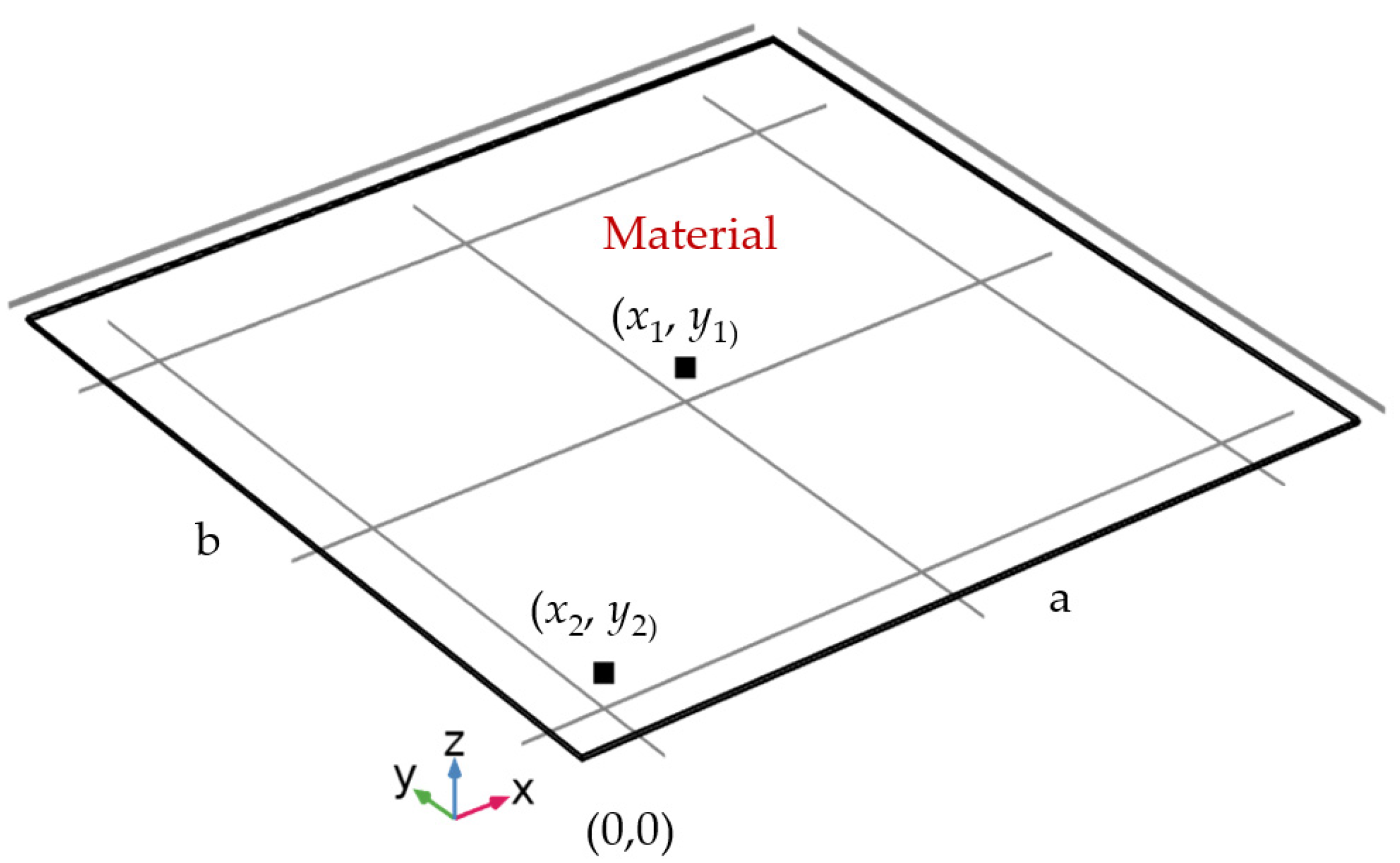
2.1. Deflection of Rigid Thin Materials

When rigid structures are excited by some manner of stress, it is possible to observe different waves propagating through their structure. Sound waves traveling in rigid structures have the capability to store energy in compression as well as in shear. The rigid materials that store acoustic energy as potential and kinetic energy could be utilized for noise and vibration control applications to permit sound wave transmission through their mediums. Kinetic energy is kept inside any part of the material that has mass in motion, while potential energy is deposited into the material components that have undergone elastic buckling.
When a homogeneous rigid material is exposed to an oblique time-dependent force, then the oblique displacement of the structure is controlled by the fourth-order differential equation. The deflection of the structure derives utterly from inertial forcing for free load conditions. A plate-like structure that has a breadth h and dimension a along the x-axis × b and along the y-axis is chosen for computational and theoretical investigation. The material displacement that is generated by bending waves is in the direction of the z-axis and is a function of time. The geometry of the material is shown in Figure 1.
The bending acoustic wave formula for rigid structures is conferred in the equation below.
D ( 2 x 2 + 2 y 2 ) 2 W s + ρ s h W s .. = F ( x , y , t )
where W s is the transverse deflection of the thin material, W s .. is the thin material deflection, D = E h 3 / ( 12 12 v 2 ) is the bending rigidity, 2 x 2 + 2 y 2 is the coordinate system, ρ s   is the solid density, E is the elastic modules for thin material, v is the material Poisson ratio, and F(x,y,t) is the time-dependent force applied on the surface of the material.
The thin material deflection W s for harmonic wave motion is expressed in Equation (2).
W s ( x , y ) = m = 0 n = 0 A m n X m ( x ) Y n ( y )
where X m is the function in the x-axis and Y n is the function in the y-axis direction. These beam functions were selected to satisfy different boundary conditions at the edges of the plate. An appropriate trigonometric function for the vibrating beams was used for X m   and   Y n different boundary conditions. A m n is the unknown coefficients; m and n are the modes, which are equal to 0, 1, 2, 3 .
The trigonometric beam functions are used to expand the material deflection for clamped rigid material. These functions are given by Equations (3) and (4).
X m ( x ) = B m 1 cosh ( a m x a ) + B m 2 cos ( a m x a ) + B m 3 sinh ( a m x a ) + B m 4 sin ( a m x a )
Y n ( y ) = C n 1 cosh ( b n y b ) + C n 2 cos ( b n y b ) + C n 3 sinh ( b n y b ) + C n 4 sin ( b n y b )
where a m is the frequency parameter responding to the mth normal modes of characteristic equation and b n is the frequency parameter responding to the nth normal modes of characteristic equation. B m 1 ,   B m 2 , B m 3 , B m 4 and C n 1 ,   C n 2 , C n 3 , C n 4 could be predicted from the boundary conditions at the boundaries of the material in the x and y directions, respectively. These constants could be applied to any boundary conditions, including fixed, simply supported, and fully constrained sides.
A rigid thin fiberglass material with dimensions 0.50 m × 0.50 m with a uniform thickness of 2.5 mm was agitated using a point force F(x,y,t) at the center of the material, at x0 = 0.25 m, and y0 = 0.25 m from the center of the material. The reactions to the force applied on the material were determined at x1 = 0.25 m and y1 = 0.25 m, and at x2 = 0.05 m and y2 = 0.05 m. A point force with a magnitude of 1 N was applied to agitate the thin material. The acoustical response of the material was predicted in the 0–500 Hz frequency range using a MATLAB code. The properties of the rigid thin material used for numerical analysis in the MATLAB code are shown in Table 1.
Normal characteristic modes (m, n) up to 20 were used for determining the deflection of the thin plate. The vibration responses of a rigid thin fiberglass plate for three boundary conditions (fully clamped “CCCC”, fully free “FFFF”, and partially clamped and partially free “CCFF”) detected at x1 = 0.25 m and y1 = 0.25 m on the plate surface are compared in Figure 2. For the fully clamped boundary condition (“CCCC”), first resonance frequency was observed at 37 Hz with a magnitude of 3.12 × 10⁻³ m, while for partially clamped/partially free boundary condition (“CCFF”), first resonance frequency was seen at 5 Hz with a magnitude of 2.701 × 10⁻³ m. For the fully free boundary condition (“FFFF”), first resonance frequency was observed at 23 Hz with a magnitude of 6.27 × 10⁻³ m. Fully clamping the plate at four edges shifted the fundamental resonance frequency to a higher frequency. Even though some differences between the three boundary conditions were seen at lower frequencies, there was a good agreement between predicted plate deflections at higher frequencies. The plate deflection curves obtained at the center of the material were to some extent similar to exponentially decaying sinusoidal wave signals. As can be observed in Figure 2, the amplitude of structural deflection at low frequencies was higher than at higher frequencies.
Furthermore, the plate deflections for three boundary conditions were determined at x2 = 0.05 m and y2 = 0.05 m on the surface of the material; they are compared in Figure 3. For the fully clamped boundary condition (“CCCC”), the fundamental resonance frequency was seen at 37 Hz with a magnitude of 4.46 × 10⁻⁵ m, while for the partially clamped/partially free boundary condition (“CCFF”), the first resonance frequency was observed at 5 Hz with a magnitude of 7.62 × 10⁻⁶ m. For the fully free boundary condition (“FFFF”), the first resonance frequency was observed at 23 Hz with a magnitude of 6.27 × 10⁻³ m, and for the fully free boundary condition “FFFF”, it was seen at 23 Hz with a magnitude of 5.37 × 10⁻³ m. At the edges of the materials, x2 = 0.05 m and y2 = 0.05 m, the amplitude of deflections varied at lower resonance frequencies, while at higher resonance frequencies, it was mostly constant.

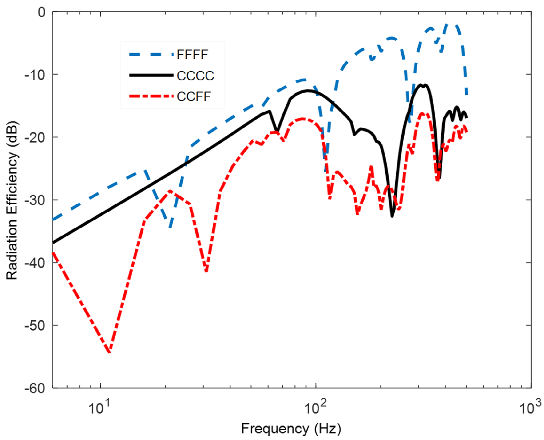
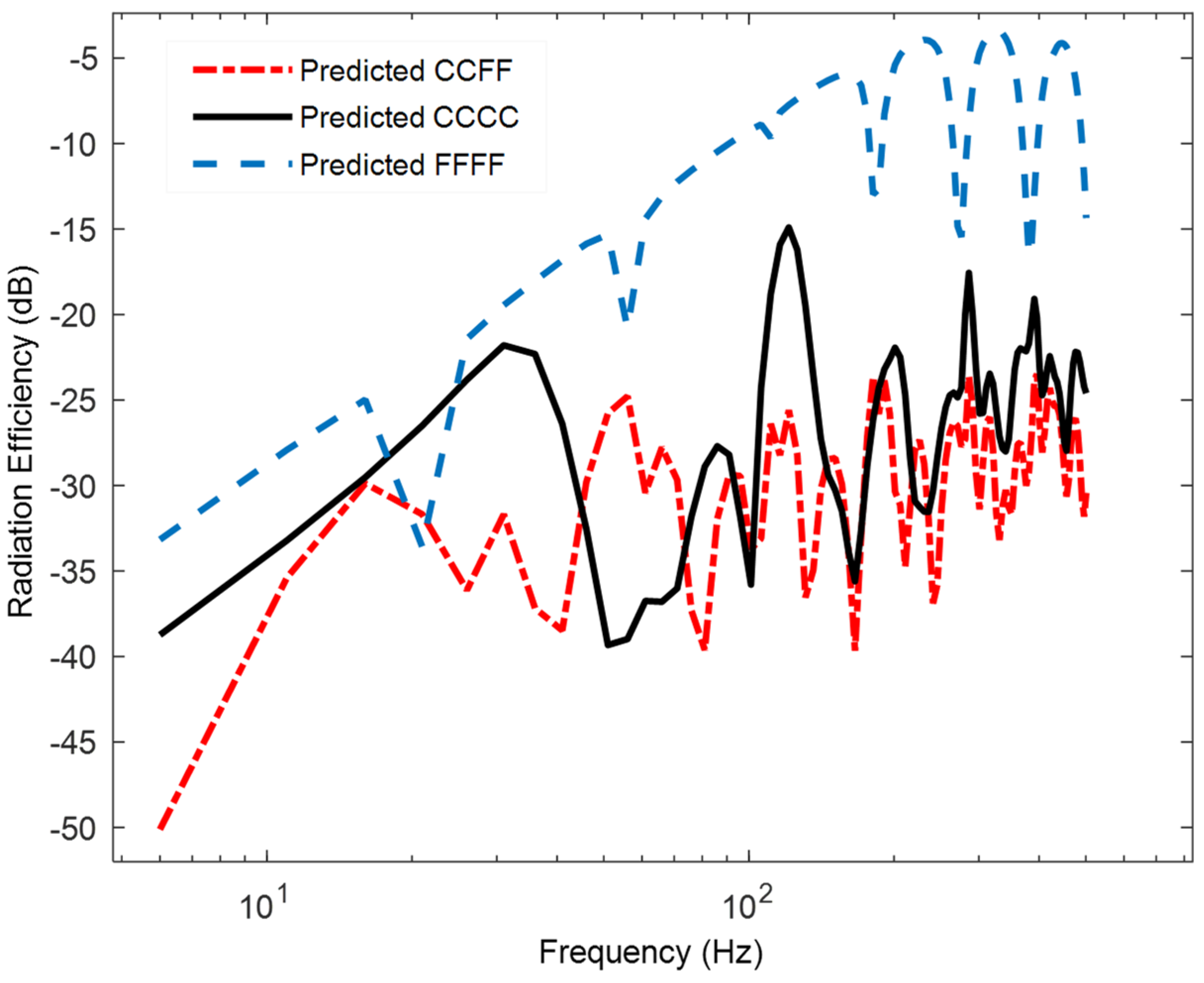
2.2. Acoustic Radiation Efficiency from Rigid Thin Materials

Acoustic radiation from rigid thin materials is related to their acoustic impedances. The vibrational behavior of rigid materials could be expressed in terms of its acoustic radiation efficiency. The dimensions and character of the exciting structure perform a valuable part in order to predict the acoustic transmission efficiency for thin material. Sound radiation efficiency is defined in terms of structural energy converted into sound energy. The magnitude of vibrating material will affect sound radiation efficiency of thin rigid materials. This could be determined by applying numerical approaches, as shown in Equation (5).
η = W Z a b V 2
where Z is the characteristic impedance of air, V is the mean square velocity, and W is the acoustic power expressing plate acoustic energy spreading into the surrounding environment due to the motion of the structure.
Sound radiation efficiencies of rigid thin material corresponding to Figure 2 were determined at x1 = 0.25 m and y1 = 0.25 m on the material surface for three boundary conditions and compared in Figure 4. The sound radiation dips observed were associated with the dips of the plate deflection seen at the same frequencies in Figure 2. For the fully free boundary condition (FFFF), radiation efficiency was higher than the radiation efficiency of the other two boundary conditions, while the lowest sound radiation efficiency was observed for the fully clamped boundary condition.
In addition, the acoustic radiation efficiency of the plate that corresponded to Figure 3 was determined at x2 = 0.05 m and y2 = 0.05 m on the plate surface for three boundary conditions. A comparison of the radiation efficiency is given in frequency domain in Figure 5. The radiation efficiency of the fiberglass material was determined in terms of the acoustic power and velocity of the fiberglass material. The radiation efficiency was reduced at lower frequencies because of larger wavelengths, while it approached unity at higher frequencies because of smaller wavelengths of acoustic waves.

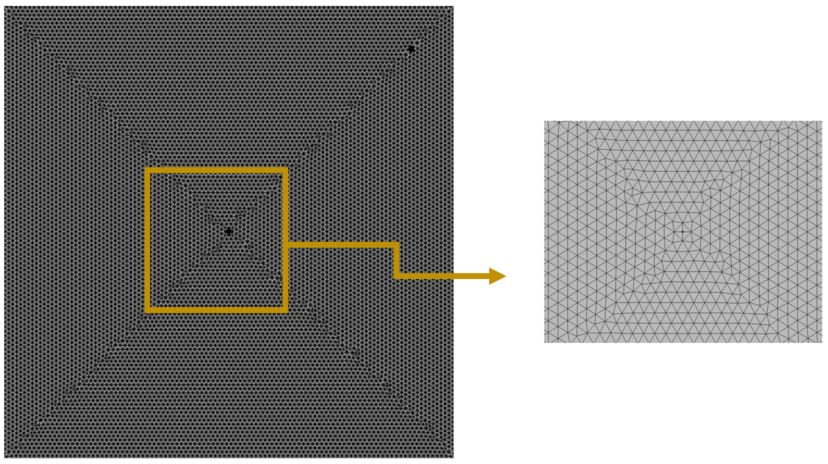
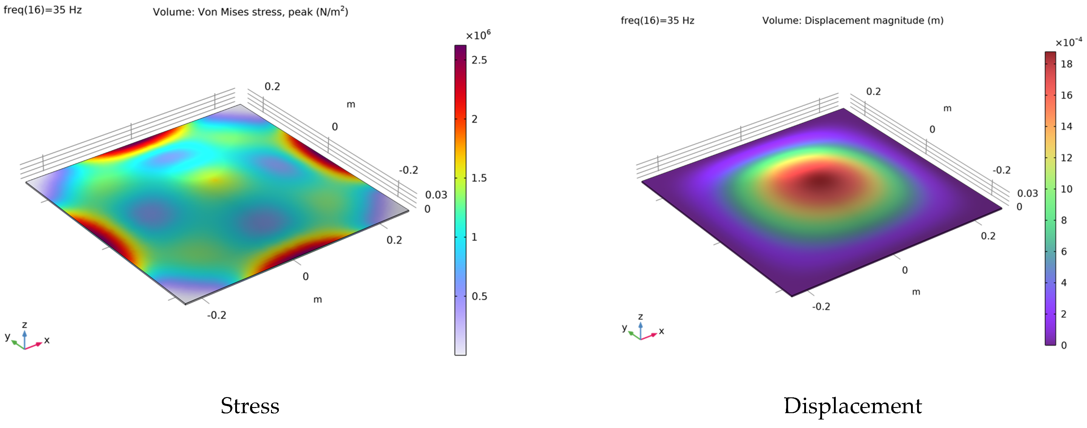
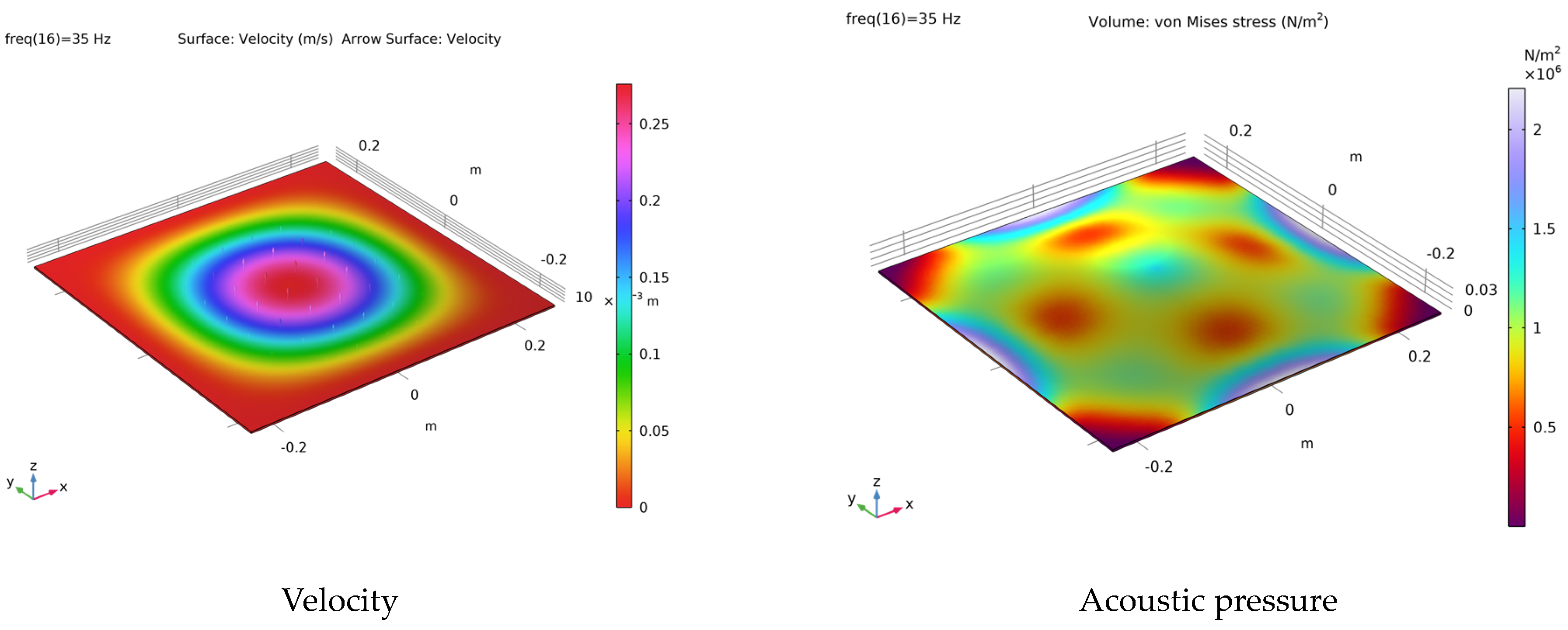
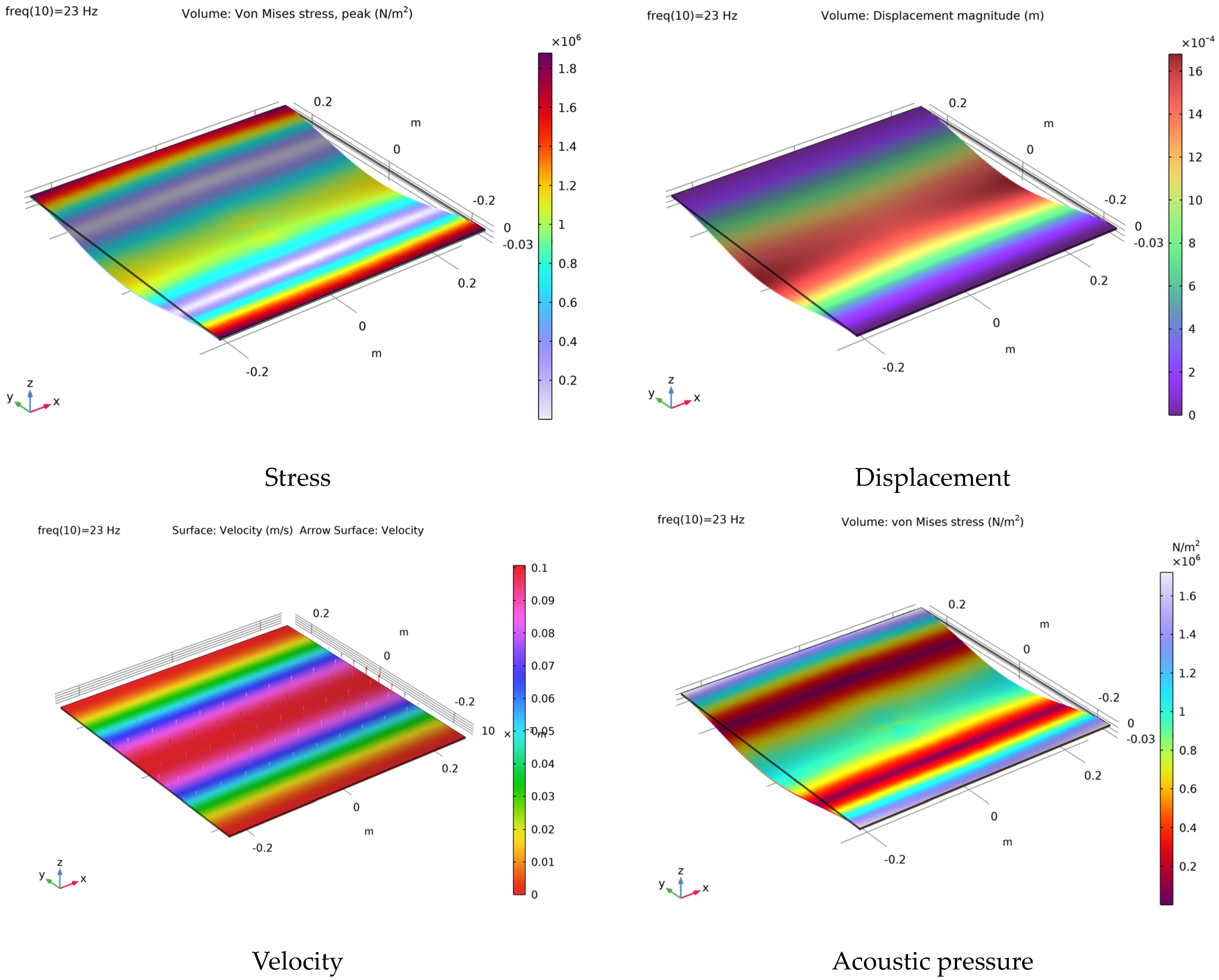
3. COMSOL Simulation of Fiberglass Materials

COMSOL multiphysics, which is a finite element method, was used to divide the continuous model into small finite modules, which were solved and then combined. The physical field of the COMSOL simulation was determined by applying the “Structural mechanics” module. A rectangular material of length of 50 cm and width of 50 cm with a 2.5 mm thickness was modeled as a two-dimensional system using the tetrahedra fine mesh of 22,432 element values. The tetrahedra fine mesh of thin rigid material is shown in Figure 6. Solid mechanics was selected for the physics interface for the general modeling of the material. The rigid thin material could be represented by the mathematical model, assuming that the in-plane stresses and strains varied linearly throughout the material thickness. Isotropic symmetry was selected as a linear elastic solid model that had the same properties in all directions.
A point load was applied to the middle of the material to excite the material, and its harmonic response was computed around its linearization point. Frequency domain analysis was used to study the response to a harmonic steady state excitation for a frequency range up to 500 Hz. Quadratic Lagrange was applied to the displacement field as geometry shape functions.
The study of controlled equation of motion (often referred to as the Kirchhoff thin plate theory) was used for the COMSOL simulation of thin material for a uniform depth of h, considering the simulations of the materials used were isotropic. The partial differential equation for acoustic waves is given by the following equation.
D 2 2 w + ρ h 2 w t 2 = q ( x , y , t )
where D is the flexural rigidity, ρ is the material density, w is the material deflection, and q is the distribution load per unit area.
The response of point load applied to the center of the material (x0 = 0.25 m and y0 = 0.25 m) were obtained at the middle of the material (x1 = 0.25 m and y1 = 0.25 m) and at another location on the surface of the material (x2 = 0.05 m and y2 = 0.05 m). The plate deflection obtained at two positions on the thin plate surface for the fully clamped (CCCC) boundary condition is given in the frequency domain in Figure 7. At the middle of the material, the highest deflection was observed at the fundamental resonance frequency of the plate at 35 Hz. The amplitude of plate deflection was reduced at higher harmonics. At x2 = 0.05 m and y2 = 0.05 m, the amplitudes of the first and second resonance frequencies were reduced significantly, while the amplitudes of the plate deflection were similar at resonance frequencies. It was clearly shown that the natural frequencies of thin plate-like structures at any point on the material surfaces would not change (except for amplitude). Stress distribution, velocity, and displacement alongside the acoustic pressure radiated from the material corresponding to the first resonance frequency at 35 Hz is given in Figure 8. The highest stress from the plate was seen in the middle of the four sides of the material, while the maximum displacement was seen in the middle of the material. Acoustic pressure visualization clearly showed the amount of sound energy from the surface of the material released to the outer surface.
Similarly, the vibration response of the fiberglass material was obtained for the partially clamped and partially free boundary condition (CCFF) at two locations, as shown in Figure 9. At x1 = 0.25 m and y1 = 0.25 m, a higher amplitude of the plate deflection was observed at a fundamental natural frequency of the fiberglass plate at 23 Hz, while the amplitude decreased at higher resonance frequencies. At x2 = 0.05 m and y2 = 0.05 m, the amplitudes of the fundamental and second resonance frequencies were significantly reduced. When a rigid material was stimulated at the center of its surface, the maximum deformation was observed at the center of the material, while its amplitude reduced with increasing distance outward towards the edge of the material. However, there were no changes to the resonance frequencies of the plate. Simulations of stress, velocity, displacement, and acoustic pressure corresponding to the first resonance frequency at 23 Hz are given in Figure 10. The maximum displacement and velocity were observed in the middle of the fiberglass material between two free edges, while the highest stress was observed along the clamped two edges of the material. Simulation of acoustic pressure clearly showed that the maximum amount of sound energy was radiated along the clamped two edges of the fiberglass materials.

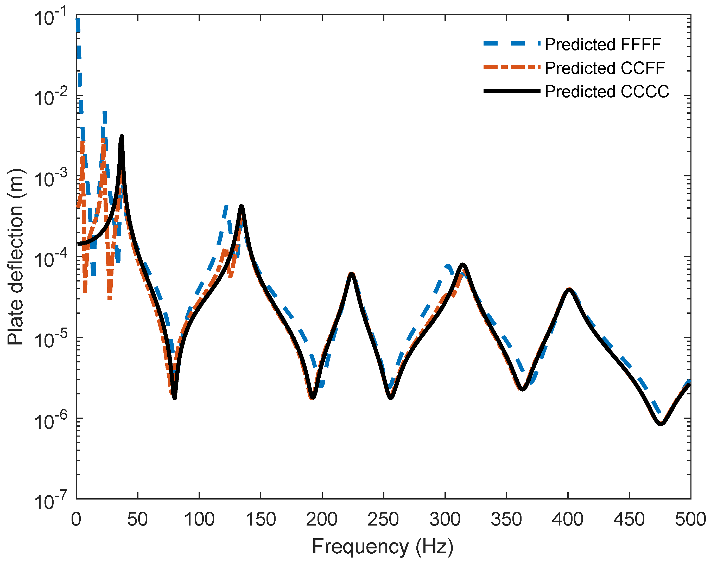
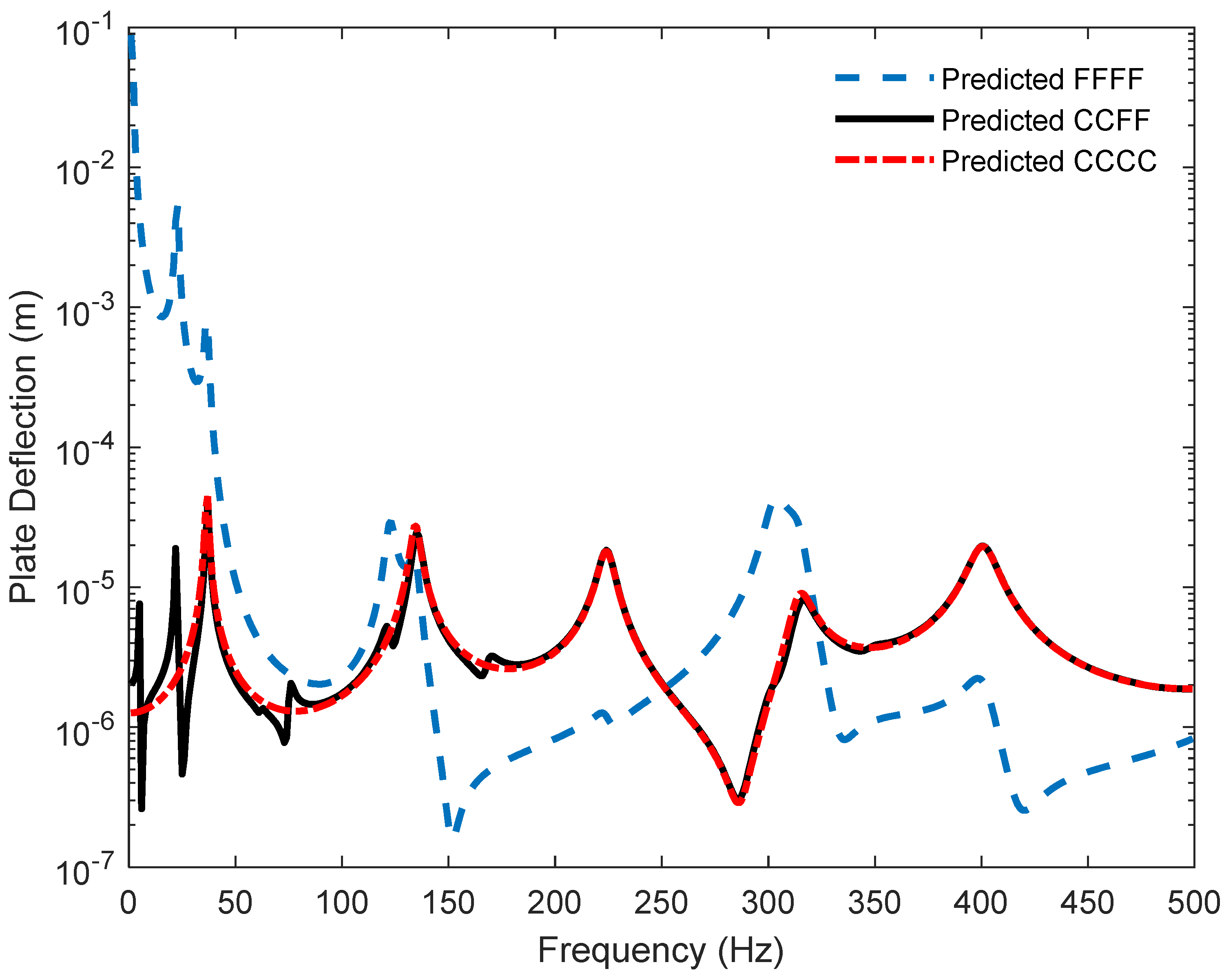
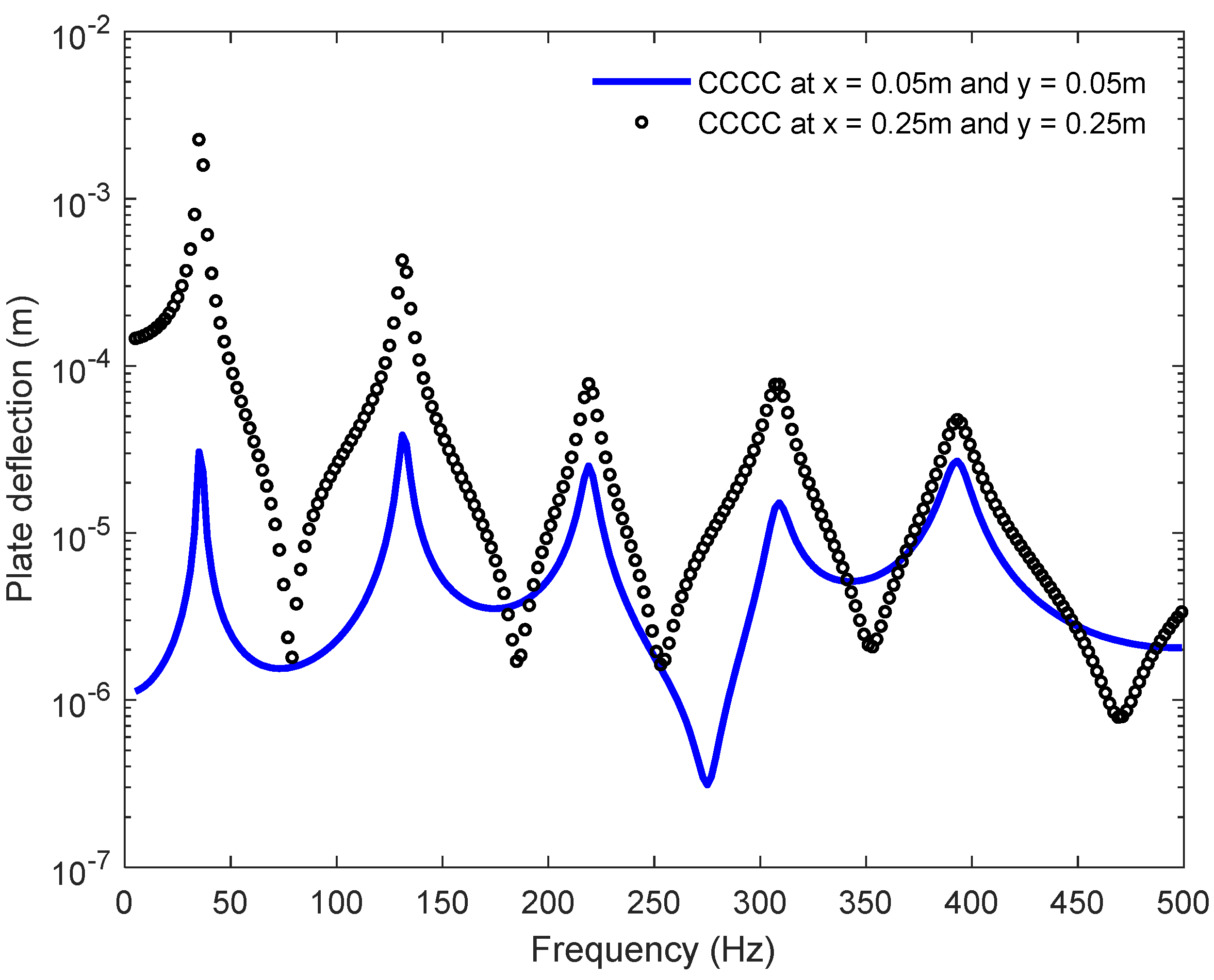
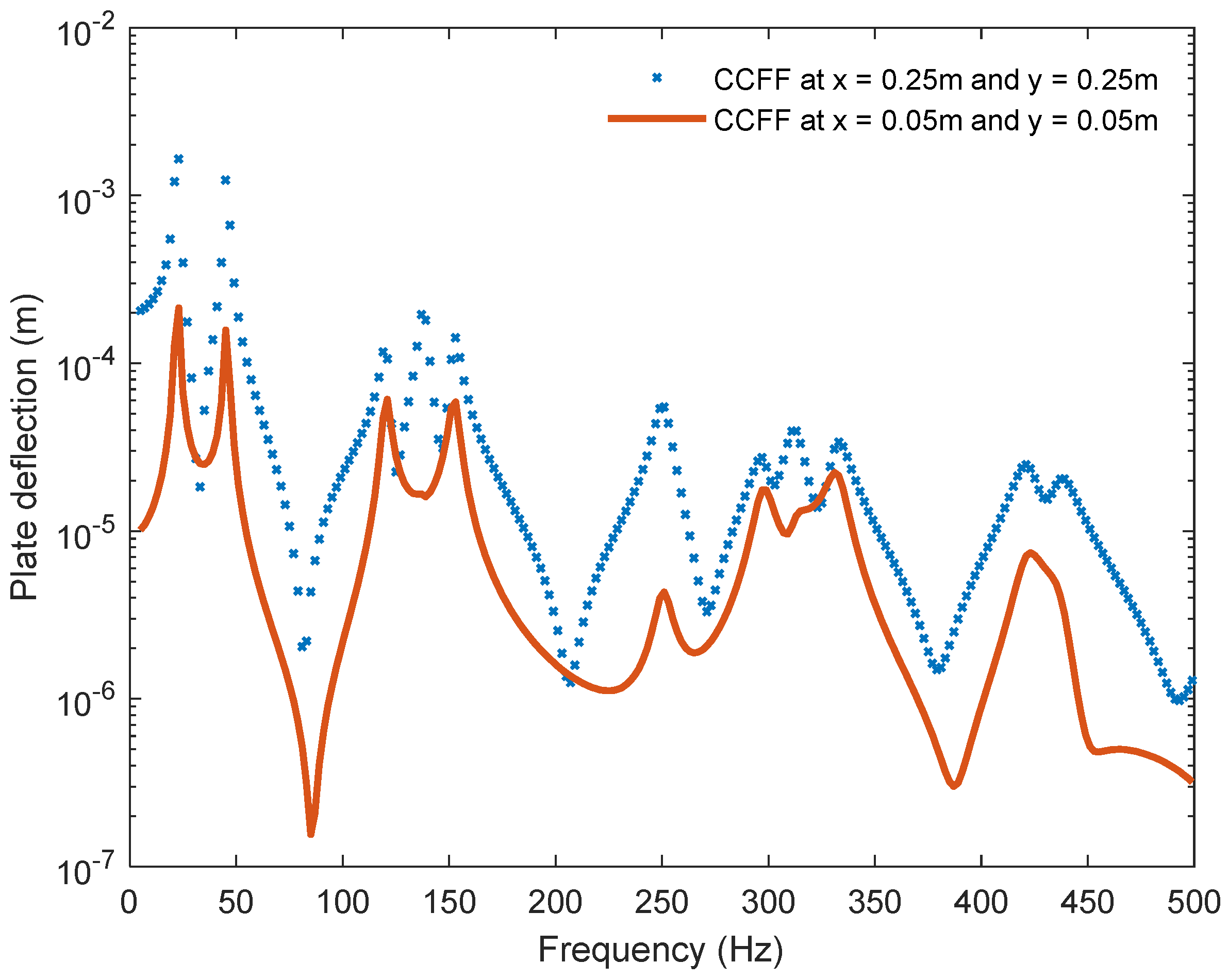
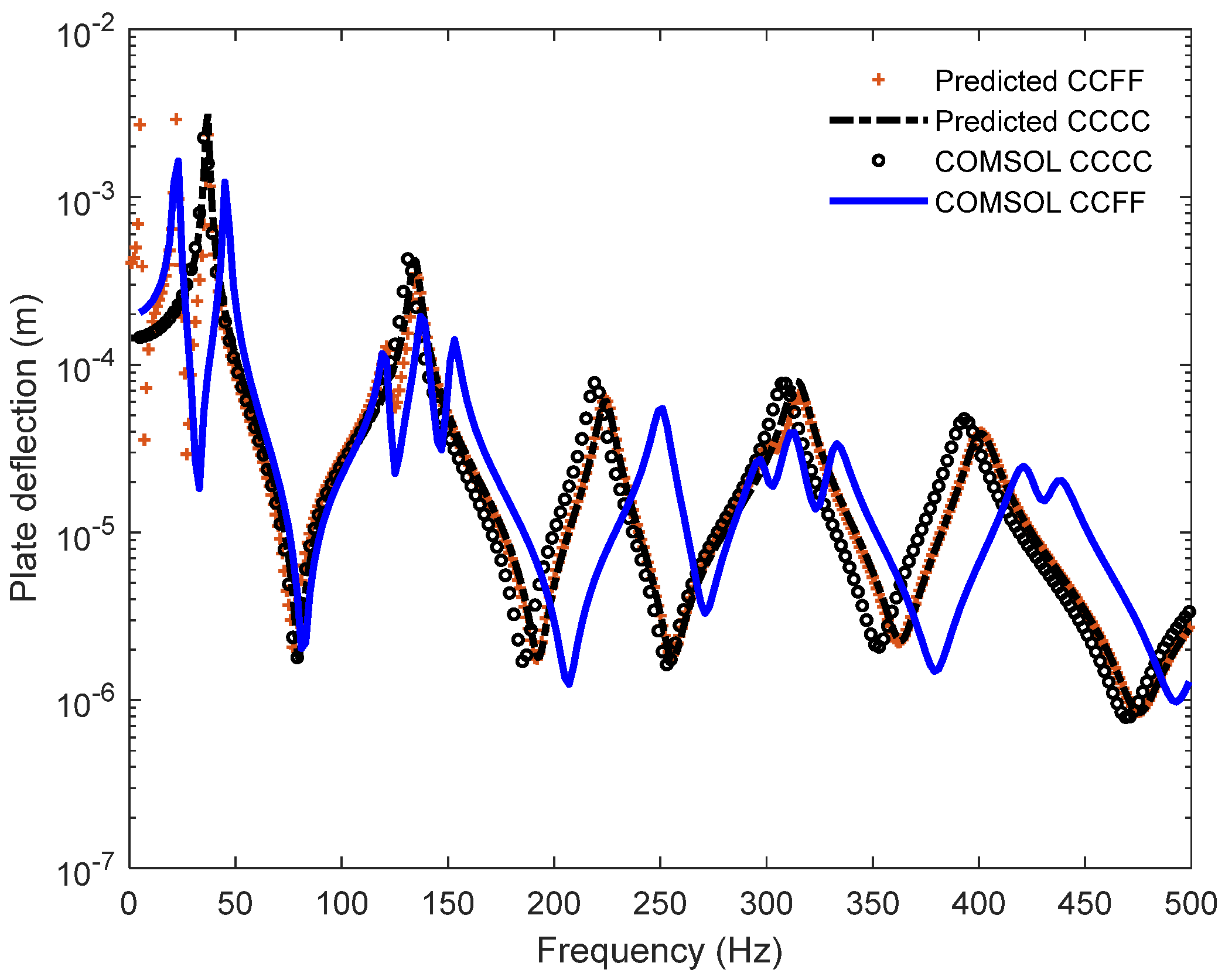
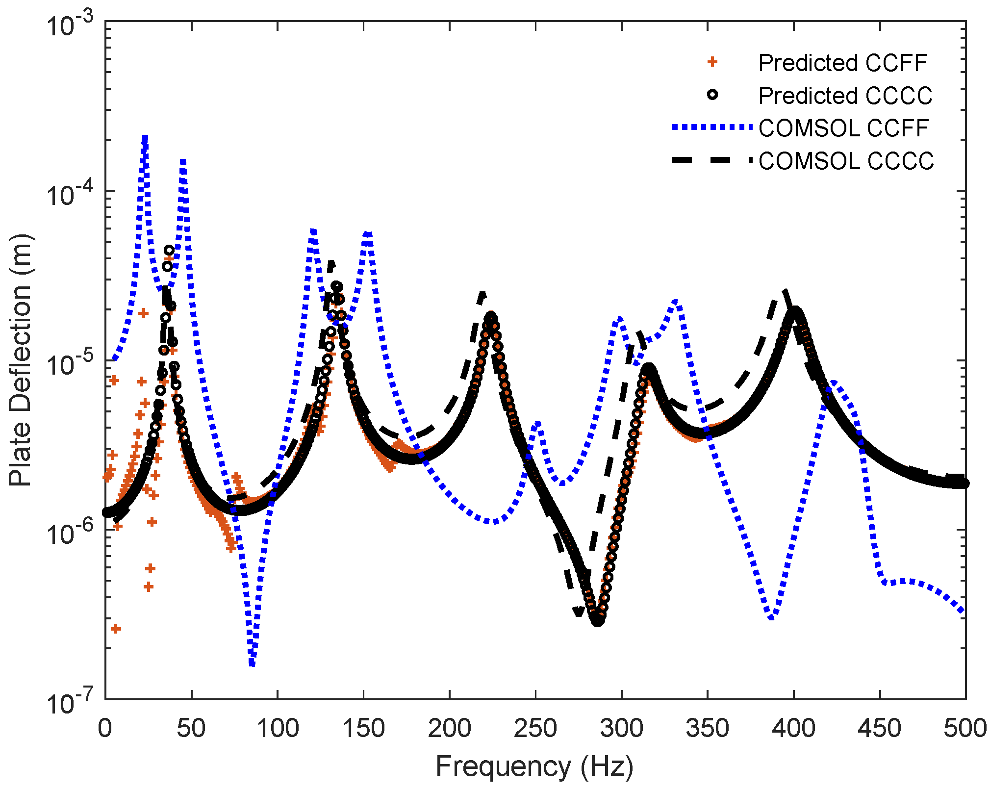
4. Comparison of Computational Simulations and Analytical Results of Vibrated Materials

Computational simulations obtained using COMSOL were compared to analytical results predicted by means of a MATLAB code in this section. The results were obtained at the center of the fiberglass plate for two boundary conditions, as shown in Figure 11. Computational plate deflection obtained with COMSOL was in good agreement and followed the same deflection pattern as the predicted plate deflection for the fully clamped boundary condition (CCCC). For the partially clamped and partially free boundary condition (CCFF), computational and predicted plate deflections were similar at lower frequencies (apart from some discrepancies between 130 Hz and 500 Hz). Furthermore, computational and predicted plate deflections at another location on the plate surface at x2 = 0.05 m and y2 = 0.05 m were obtained and compared in Figure 12. Computational and predicted plate deflections were similar for the fully clamped boundary condition (CCCC) throughout the frequency range, but there were some discrepancies between them for the partially clamped and partially free boundary condition (CCFF).

5. Conclusions

Computational and theoretical investigations of the vibrational and acoustical properties of rigid thin material were carried out. Theoretical deflection of the plate was obtained for three different boundary conditions at two locations on the surface of the material, while computational plate deflections were only obtained for two boundary conditions. It was observed that, for the fully clamped boundary condition, the amplitude of predicted plate deflection at the center of the material decreased with increasing resonance frequencies and maximum amplitude was obtained at the fundamental frequency of the plate, while the amplitude of the plate deflections obtained at a location closer to the edge of the material was almost at the same amplitude at the resonance frequencies. Overall, computational results were in good agreement with predicted plate deflections determined at two locations on the plate surface for two boundary conditions.
Sound radiation efficiency was theoretically determined for three boundary conditions at two locations on the surface of the fiberglass plate. The results clearly confirmed that the radiation efficiencies obtained in Figure 4 and Figure 5 corresponded to the plate deflections obtained in Figure 2 and Figure 3. Theoretical radiation efficiencies suggested that the fiberglass material had a good radiation efficiency throughout the frequency range, especially for the fully free boundary condition.
Computational and theoretical results showed that rigid thin fiberglass material could be applied to isolate the vibration of machines and the mechanical vibration of structures. They could be used to cover outdoor noise barriers to extend the lifespan of the barriers by protecting them from rain, cold weather, and direct sunlight. In addition, they could be applied to construct panels that are produced by sandwiching structures between fiberglass sheets to decrease airborne noise and also to reduce the transmission of structural borne noise.

Funding

This research received no external funding.

Data Availability Statement

The data presented in this study are available in the article.

Acknowledgments

This work was supported by Acoustic Research Centre, and Centre for Civil and Building Services Engineering of London South Bank University.

Conflicts of Interest

The author declares no conflict of interest.

References

  1. Szilard, R. Theory and Analysis of Plates. In Classical and Numerical Methods; Prentice-Hall: Englewood, NJ, USA, 1974. [Google Scholar]
  2. Leissa, A.W. The free vibration of rectangular plates. J. Sound Vib. 1973, 1, 257–293. [Google Scholar] [CrossRef]
  3. Young, D. Vibration of rectangular plates by the Ritz method. J. Appl. Mech. 1950, 17, 448–453. [Google Scholar] [CrossRef]
  4. Theodorakopoulos, D.D.; Beskos, D.E. Flexural vibration of poroelastic plates. Acta Mech. 1994, 103, 191–203. [Google Scholar] [CrossRef]
  5. Biot, M.A. Theory of elastic wave propagation in a fluid saturated porous solid. Part I-low frequency range. J. Acoust. Soc. Am. 1956, 28, 168–178. [Google Scholar] [CrossRef]
  6. Biot, M.A. Theory of elastic wave propagation in a fluid saturated porous solid. Part 2-higher frequency range. J. Acoust. Soc. Am. 1956, 28, 179–191. [Google Scholar] [CrossRef]
  7. Leclaire, P.; Cummings, A.; Horoshenkov, K.V. Transverse vibration of a thin rectangular porous plate saturated by a fluid. J. Sound Vib. 2001, 247, 1–18. [Google Scholar] [CrossRef]
  8. Leclaire, P.; Horoshenkov, K.V.; Swift, M.J.; Hothersall, D.C. The vibration response of a clamped rectangular porous plate. J. Sound Vib. 2001, 217, 19–31. [Google Scholar] [CrossRef]
  9. Aygun, H.; Attenborough, K. Predicted effects of fluid loading on the vibration of elastic porous plates. Acta Acoust. United Acust. 2007, 93, 284–289. [Google Scholar]
  10. Aygun, H.; Attenborough, K. Sound absorption by clamped poroelastic plates. J. Acoust. Soc. Am. 2008, 124, 1550–1556. [Google Scholar] [CrossRef]
  11. Davies, H.G. Low frequency random excitation of water-loaded rectangular plates. J. Sound Vib. 1971, 15, 107–126. [Google Scholar] [CrossRef]
  12. Pope, L.D.; Leibowitz, R.C. Intermodal coupling coefficients for a fluid-loaded rectangular plate. J. Acoust. Soc. Am. 1974, 56, 408–414. [Google Scholar] [CrossRef]
  13. Gomperts, M.C. Radiation from rigidly baffled rectangular panels with general boundary conditions. Acustica 1974, 30, 320–327. [Google Scholar]
  14. Gomperts, M.C. Sound radiation from baffled, thin, rectangular plates. Acustica 1977, 37, 93–102. [Google Scholar]
  15. Berry, A. A general formulation for the sound radiation from rectangular, baffled plates with arbitrary boundary conditions. J. Acoust. Soc. Am. 1990, 88, 2792–2802. [Google Scholar] [CrossRef]
  16. Berry, A. A new formulation for the vibrations and sound radiation of fluid-loaded plates with elastic boundary conditions. J. Acoust. Soc. Am. 1994, 96, 889–901. [Google Scholar] [CrossRef]
  17. Atalla, N.; Nicolas, J. A new tool for predicting rapidly and rigorously the radiation efficiency of plate-like structures. J. Acoust. Soc. Am. 1994, 95, 3369–3378. [Google Scholar] [CrossRef]
  18. Foin, O.; Nicolas, J.; Atalla, N. An efficient tool for predicting the structural acoustic and vibration response of sandwich plates in light or heavy fluid. Appl. Acoust. 1999, 57, 213–242. [Google Scholar] [CrossRef]
  19. Sandman, B.E. Motion of a three-layered elastic-viscoelastic plate under fluid loading. J. Acoust. Soc. Am. 1975, 57, 1097–1107. [Google Scholar] [CrossRef]
  20. Nelisse, H.; Beslin, O.; Nicolas, J. Fluid–structure coupling for an unbaffled elastic panel immersed in a diffuse field. J. Sound Vib. 1996, 198, 485–506. [Google Scholar] [CrossRef]
  21. Nelisse, H.; Beslin, O.; Nicolas, J. A generalized approach for the acoustic radiation from a baffled or unbaffled plate with arbitrary boundary conditions, immersed in a light or heavy fluid. J. Sound Vib. 1998, 211, 207–225. [Google Scholar] [CrossRef]
  22. McCann, F.; Aygun, H. Structural and acoustical performance of recycled glass bead panels. J. Constr. Build. Mater. 2020, 258, 119581. [Google Scholar]
  23. Singh, B.N.; Hota, R.N.; Dwivedi, S.; Jha, R.; Ranjan, V.; Rehak, K. Analytical investigation of sound radiationfrom functionally graded thin plates based onelemental raditor approach and phsycialneutral surface. J. Appl. Sci. 2022, 12, 7707. [Google Scholar] [CrossRef]
  24. Ziao, X.; Tao, J.; Sun, H.; Sun, Q. Modeling of Acoustic Vibration Theory Based on a Micro Thin Plate System and Its Control Experiment Verification. J. Sustain. 2022, 14, 14900. [Google Scholar]
  25. Liu, C.W.; Kam, T.Y. Free Vibration of Rectangular Composite Cantilever Plate and Its Application in Material Degradation Assessment. J. Appl. Sci. 2023, 13, 5101. [Google Scholar] [CrossRef]
Figure 1. Rigid thin material geometry.
Acoustics 06 00005 g001
Figure 2. Comparison of deflection of fiberglass material for three boundary conditions: clamped at four edges (CCCC), four edges are free (FFFF), and clamped at two opposite edges and free at the other two opposite edges (CCFF) at x1 = 0.25 m and y1 = 0.25 m on the plate surface. The results are given in the frequency domain. “C” means clamped edge and “F” means free edge.
Acoustics 06 00005 g002
Figure 3. Comparison of the deflection of fiberglass material for three boundary conditions: clamped at four edges (CCCC), four edges are free (FFFF), and clamped at two opposite edges and free at the other two opposite edges (CCFF). The response is calculated at x2 = 0.05 m and y2 = 0.05 m on the plate surface and given in the frequency domain.
Acoustics 06 00005 g003
Figure 4. Comparison of acoustic radiation efficiency of vibrated fiberglass plate for three boundary conditions: clamped at four edges (CCCC), four edges are free (FFFF), and clamped at two opposite edges and free at the other two opposite edges (CCFF). The response is obtained at x1 = 0.25 m and y1 = 0.25 m on the material surface and given in the frequency domain.
Acoustics 06 00005 g004
Figure 5. Comparison of acoustic radiation efficiency of vibrated fiberglass material for three boundary conditions: clamped at four edges (CCCC), four edges are free (FFFF), and clamped at two opposite edges and free at the other two opposite edges (CCFF). The response is obtained at x2 = 0.05 m and y2 = 0.05 m on the plate surface and given in the frequency domain.
Acoustics 06 00005 g005
Figure 6. The tetrahedra fine mesh of thin rigid material.
Acoustics 06 00005 g006
Figure 7. Plate deflection for fully clamped (CCCC) at four edges boundary condition versus frequency domain for two different locations on the plate at x1 = 0.25 m and y1 = 0.25 m and at x2 = 0.05 m and y2 = 0.05 m.
Acoustics 06 00005 g007
Figure 8. Computational simulation of clamped plate behaviors at a first resonance frequency of 35 Hz.
Acoustics 06 00005 g008aAcoustics 06 00005 g008b
Figure 9. Computational simulation of plate deflection when two edges are clamped and two edges are free, CCFF, versus frequency domain. Responses are obtained at two different locations at x1 = 0.25 m and y1 = 0.25 m and at x2 = 0.05 m and y2 = 0.05 m.
Acoustics 06 00005 g009
Figure 10. Computational behavior of plate vibration at first resonance frequency of 23 Hz. Boundary condition includes clamped two opposite edges and free other two opposite edges.
Acoustics 06 00005 g010
Figure 11. Comparison of computational and predicted deflection of fiberglass material for two boundary conditions: clamped at four edges (CCCC) and clamped at two opposite edges and free at the other two opposite edges (CCFF). The response is obtained at the center of the materials, x1 = 0.25 m and y1 = 0.25 m, on the plate surface and given in the frequency domain.
Acoustics 06 00005 g011
Figure 12. Comparison of computational and predicted deflection of fiberglass material for two boundary conditions: clamped at four edges (CCCC) and clamped at two opposite edges and free at the other two opposite edges (CCFF). The response is obtained at x2 = 0.05 m and y2 = 0.05 m on the plate surface and given in the frequency domain.
Acoustics 06 00005 g012
Table 1. Characteristics of rigid material.
Length (cm)Width (cm)Depth (mm)Solid Density (kg/m3)Elastic Modulus (GPa)Loss FactorPoisson Ratio
50502.516007.4890.030.2
Disclaimer/Publisher’s Note: The statements, opinions and data contained in all publications are solely those of the individual author(s) and contributor(s) and not of MDPI and/or the editor(s). MDPI and/or the editor(s) disclaim responsibility for any injury to people or property resulting from any ideas, methods, instructions or products referred to in the content.

