Article

Strategies to Hierarchical Porosity in Carbon Nanofiber Webs for Electrochemical Applications

Institut Charles Gerhardt Montpellier, UMR CNRS 5253, Agrégats Interfaces et Matériaux pour l’Energie, Université de Montpellier - ENSCM - CNRS, CEDEX 5, 34095 Montpellier, France
*
Author to whom correspondence should be addressed.
Surfaces 2019, 2(1), 159-176; https://doi.org/10.3390/surfaces2010013
Submission received: 4 February 2019 / Revised: 22 February 2019 / Accepted: 25 February 2019 / Published: 5 March 2019
(This article belongs to the Special Issue Electrochemical Surface Science: Basics and Applications)

Abstract

:
Morphology and porosity are crucial aspects for designing electrodes with facile transport of electrons, ions and matter, which is a key parameter for electrochemical energy storage and conversion. Carbon nanofibers (CNFs) prepared by electrospinning are attractive for their high aspect ratio, inter-fiber macroporosity and their use as self-standing electrodes. The present work compares several strategies to induce intra-fiber micro-mesoporosity in self-standing CNF webs prepared by electrospinning polyacrylonitrile (PAN). Two main strategies were investigated, namely i) a templating method based on the addition of a porogen (polymethyl methacrylate, polyvinylpyrrolidone, Nafion® or ZnCl2) in the electrospinning solution of PAN, or ii) the activation in ammonia of previously formed CNF webs. The key result of this study is that open intra-fiber porosity could be achieved only when the strategies i) and ii) were combined. When each approach was applied separately, only closed intra-fiber porosity or no intra-fiber porosity was observed. In contrast, when both strategies were used in combination all CNF webs showed high mass-specific areas in the range of 325 to 1083 m2·g−1. Selected webs were also characterized for their carbon structure and electrical conductivity. The best compromise between high porosity and high electrical conductivity was identified as the fibrous web electrospun from PAN and polyvinylpyrrolidone.

Graphical Abstract

1. Introduction

The performance of electrodes in electrochemical energy storage and conversion devices strongly depends on two key factors: a) the density of active sites or active area where faradaic or capacitive phenomena occur; and b) the mass- and charge-transport of species (gases, liquids, ions and electrons) to and from the active sites across the porous electrode [1,2]. The design of porous and hollow nanostructures is crucial to obtain high surface areas, nanoscale porous structures and a high density of electrochemically accessible active sites. In particular, carbon is widely used as a support (e.g., for fuel cells) or as an active material (e.g., in supercapacitors and in some batteries) due to its sufficiently high electrical conductivity, low cost and reasonable stability in specific electrochemical potential windows.
Among carbon materials, carbon nanofibers (CNFs) are very promising for the fabrication of electrochemical electrodes due to their high aspect ratio and the possibility to assemble CNFs in unique three-dimensional web structures with very high macropore volume between the fibers. High porosity within electrodes is critical to avoid a slow Knudsen diffusion regime in gas-diffusion electrodes (as in fuel cells), or to avoid reactant/ion depletion (in supercapacitors, redox flow batteries, etc.). A very efficient and upscalable approach to prepare a CNF network is via the electrospinning and carbonization of a polymer solution [3,4]. Furthermore, CNF webs obtained via electrospinning can often be designed to possess sufficient mechanical stability and through-plane electric conductivity to be used as free-standing electrodes, as shown in recent studies on batteries [5,6], supercapacitors [7,8,9], fuel cells [10,11,12], vanadium redox-flow [13] and Li–O2 batteries [14]. This technique may not only simplify the electrode fabrication process, but also maximizes the macropore volume in the electrode and avoids binders, otherwise necessary with dispersed CNFs or other carbon powder materials to form the electrode. Such binders or additives often reduce the accessibility of active sites by ions in the electrolyte, by electrons from the current collector and/or by reactants in the gas-phase or in the electrolyte.
Electrospun CNFs are generally prepared by electrospinning a polymer precursor (e.g., polyacrylonitrile (PAN), polyimide, polybenzimidazole or polyvinyl alcohol), followed by at least one thermal treatment to convert the polymer fibrous network into conductive carbon [15]. The nature and molecular weight of the polymer precursor, its concentration in the electrospun solution as well as the thermal treatment conditions all can influence the morphological and physical properties of the CNF web obtained. Typical CNF diameters obtained are in the range 100–500 nm, resulting in specific surface area in the range of 4–40 m2·g−1 if the CNF does not possess internal porosity. In order to improve the specific surface area of CNF-based electrodes obtained by electrospinning, and therefore their electrochemical properties, it is crucial to develop strategies that result in CNF webs with internal porosity inside the fibers. The other possible approach, namely reducing the CNF diameter to <10 nm (to result in an expected specific area of ca 200 m2·g−1), is limited both in terms of the possible increase of specific area and also by the limitations of the mechanical stability of a CNF web with such an ultralow fiber diameter.
Two main strategies have been investigated previously to prepare porous carbon fibers by electrospinning, one in which a porogen is introduced in the electrospinning solution and which results in biphasic polymer-porogen fibers, and another in which the plain CNFs are subjected after their synthesis to a reactive chemical (gas or solid). In the former case (labelled “pre-synthesis”), the carbonization of the biphasic polymer fibers leads to the selective removal of the porogen during the temperature ramp-up, resulting in CNFs having either a closed or open porosity. In the second case (labelled “post-synthesis”), the selective etching of less-organized carbon domains in the CNFs by the reactive chemical may result in the formation of open pores from the outer surface of CNFs and the inward. However if the carbon structure of the CNF is homogeneous the reactive etching may simply result in a thinning of the CNF, without the creation of internal porosity.
In the pre-synthetic approach, the electrospinning technique allows for the introduction of various porogens in the polymer precursor solution, whereby the porogen acts as a hard or soft template during the subsequent carbonization step. The most studied hard templates for preparing CNFs are preformed nanoparticles or nanostructures (silica [8,16], nano-CaCO3 [17]) that generate porosity upon their removal with chemical and/or thermal treatments. The hard template approach allows control of the size and morphology of the pores and minimizes undesired chemical reactions between the template and the carbon structure [18]. Hard templates can also form during the carbonization treatment itself, as is the case when introducing metal salts (e.g., Co(NO3)2 6H2O, Ni(CH3COO)2, ZnCl2) in the electrospun polymer solution. The transition metal salts form metallic or metal oxide particles (e.g., Co, Ni, ZnO), which then serve as porogen, and in some cases, as a catalyst for enhanced graphitization of the CNF formed from the polymer precursor carbonization [19,20,21,22,23]. Other templates including Prussian blue analogues [24] and metal organic frameworks [25,26,27] have been used in conjunction with polymer precursors, conferring both porosity and heteroatom doping to CNFs obtained by electrospinning and carbonization. Sacrificial polymers or organic molecules such as polymethyl methacrylate (PMMA) [6,14,28,29,30], polyvinylpyrrolidone (PVP) [31,32], poly(ethylene oxide) [33], Nafion® [34], polysulfone [35], polystyrene [36], poly-L-lactic acid [37] and beta-cyclodextrin [38] can also be spun together with the main carbon precursor (any polymer forming conductive carbon with high yield during pyrolysis), allowing the formation of porous CNFs upon their removal by solvent or thermal treatment. Different kinds of templates can further be combined to produce hierarchical porosity, which is crucial for the transport of different species (ions, gases, liquids) in the electrodes of various electrochemical devices. For instance, the combination of PVP with Mg salts [22,39] gave rise to hierarchical meso- and microporosity inside CNFs prepared by electrospinning. For the post-synthetic approach, various chemical activations have been investigated to create porosity in preformed CNFs. Immersion of CNFs in concentrated KOH solutions followed by a treatment at high temperature is a recognized approach [40,41]. Other more direct approaches consist of re-pyrolyzing the CNFs in a reactive atmosphere, such as steam [42,43] or ammonia [44].
While a number of studies on CNFs prepared by resorting to either a pre-synthetic approach involving a given porogen and given carbon precursor, or a post-synthetic approach, few studies have compared the merits of using different porogens in otherwise identical preparation conditions for CNFs, and even less studies have reported on the combination of i) porogen-PAN electrospun solution and ii) a post-synthetic treatment to further increase intra-fiber porosity. In this paper, we therefore investigated the formation of intra-fiber porosity in self-standing CNF webs that were derived from electrospun PAN, resorting either to pre-synthetic and/or post-synthetic approaches to create porosity. PAN was selected for its relatively high melting point, high carbon yield and facility to be electrospun [15]. For the pre-synthetic approach, various hard (ZnCl2) and soft templating agents (PMMA, PVP, Nafion®) were co-electrospun with PAN. For the post-synthetic approach, NH3 pyrolysis was applied to CNF webs derived from electrospun porogen-PAN solutions. The resulting CNF webs were characterized for their properties relevant to electrochemical applications, including not only mass-specific surface area and porosity, but also morphology, structure, composition and electrical conductivity.

2. Materials and Methods

To prepare reference CNFs, PAN (Mw = 150,000 g·mol−1, Sigma-Aldrich, Saint Louis, MO, USA) was first dissolved in N,N-dimethylformamide (DMF, pure, Carlo Erba, Val de Reuil, France) for 12 h at 50 °C (10 wt % PAN concentration), after which the solution was cooled to room temperature. The polymer fibers were then electrospun at 20 °C and collected on a drum rotating at 100 rpm (Spraybase ®, Dublin, Ireland). The distance between the tip of the needle (22 gauge) and the collector was 10 cm, and a voltage of 13 kV (Auto-Reversing High Voltage Power Supply Spellman CZE1000R, West Sussex, United Kingdom) was applied to obtain a stable Taylor cone. The flow rate was kept as a constant 1 mL·h−1 (syringe pump KDS 100 Legacy Syringe Pump, KD Scientific, Holliston, MA, USA).
The obtained PAN-based fibers were submitted to stabilization and carbonization to give rise to carbon materials [45,46]. In particular, the electrospun PAN fibers were treated in air at 150 °C for 2 h with a heating rate of 2.5 °C·min−1, and then at 250 °C for 3 h with a heating rate of 2.5 °C·min−1. The stabilized nanofibers were finally carbonized at 1000 °C (ramp rate 5 °C·min−1) for 2 h under flowing argon atmosphere. After 2 h at 1000 °C, the heating was stopped and the sample cooled down naturally to room temperature under flowing Ar. The obtained CNFs are labelled PAN10-CNF, the scalar 10 standing for the wt % PAN in DMF solution.
To prepare biphasic polymer fibers comprising PAN, the porogen was solubilized or dissolved in a PAN/DMF solution. The investigated porogens are PMMA (Sigma-Aldrich, Mw = 15,000 or 120,000 g·mol−1), PVP (Sigma-Aldrich, Mw ~1,300,000 g·mol−1, Steinheim, Germany), Nafion® (NR50, Sigma-Aldrich, Saint Louis, MO, USA) and zinc chloride (ZnCl2 anhydrous, >98%, purchased from Alfa Aesar, Kander, Germany). For PMMA and ZnCl2, the PAN and/or porogen concentrations in DMF were varied, since the introduction of the porogen had an obvious influence on rheological properties of the solution and morphology of the electrospun polymer fiber web. Table 1 details the investigated compositions of the electrospun solutions. Such biphasic polymer fibers were stabilized in air and carbonized in flowing Ar in the exact same conditions as described above for pure-PAN based fibers. The final materials are labelled as Porogenx-PANy-CNF, with x standing for the wt % of porogen in the electrospun solution, y the wt % of PAN in the electrospun solution, and CNF indicating the pyrolysis was performed in Ar (see labels in Table 1).
Chemical activation of selected CNFs was performed by applying a flash pyrolysis in ammonia at 900 °C. Unless otherwise indicated, the pyrolysis duration in ammonia was 15 min. The resulting materials are identified by their label ending with ACNF, instead of CNF for non-activated material.
The morphology of the polymer fibers and/or CNFs was investigated by field emission-scanning electron microscopy (FE-SEM) using a Hitachi S-4800 microscope (Hitachi Europe SAS, Velizy, France). Data analysis and fiber diameter distribution were performed using an image processing software Image J 1.48 v (U. S. National Institutes of Health, Bethesda, MD, USA). CNFs were analyzed by transmission electron microscopy (TEM) using a JEOL 2200FS (Source: FEG) microscope operating at 200 kV equipped with a CCD camera Gatan USC (16 MP) (Tokyo, Japan). For TEM cross-sectional analysis, a microtome was used on resin-encapsulated sample and slices were deposited on carbon-coated copper grids (Agar Scientific, Stansted, Essex, United Kingdom).
Surface area and porosimetry of the samples were analyzed with N2 physisorption with a Tristar II Micromeritics instrument (Norcross, GA, USA) at 77 K. Prior to analysis, all samples were outgassed overnight at 120 °C under vacuum. The resulting isotherms being of type I according to the IUPAC classification, BET plots were drawn below the relative pressure of 0.1 from the adsorption branches and employed to evaluate the BET specific surface (SBET). The alpha-plot method was utilized to determine the mesoporous (Vmeso) and microporous volumes (Vmicro) as well as average pore diameter (dpore).
C, H, N, O elemental analysis was performed with a Vario MICRO Element Analyzer (Elementar Analysensysteme, Hanau, Germany).
Raman spectra were recorded on a LabRAM Aramis IR2 Horiba Jobin Yvon spectrometer (Villeneuve d’Ascq, France) equipped with a He/Ne laser (λ = 633 nm) and a long work distance objective ×50. The spectra were fitted with five bands using Origin software (OriginLab Corporation, Northampton, UK).
The in-plane electrical conductivity of self-standing CNF webs was measured using a 2400 Keithley in a four-electrode configuration on a 5 mm × 40 mm × 0.05 mm carbon electrode strip in a Fumatech MK3-L cell operated in the current range of 0–100 mA.

3. Results and Discussion

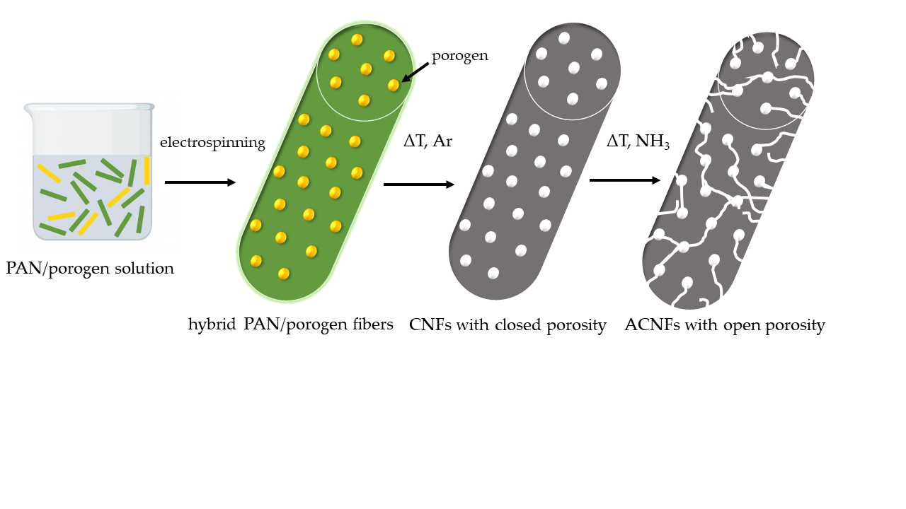
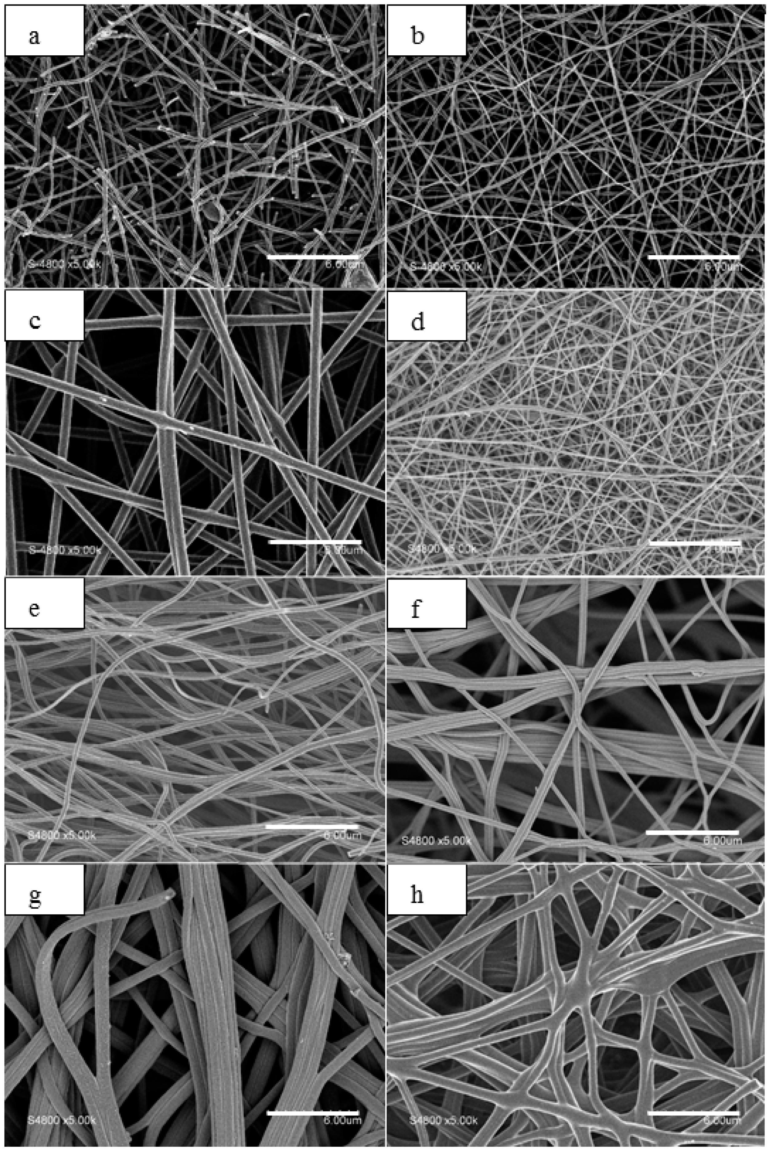
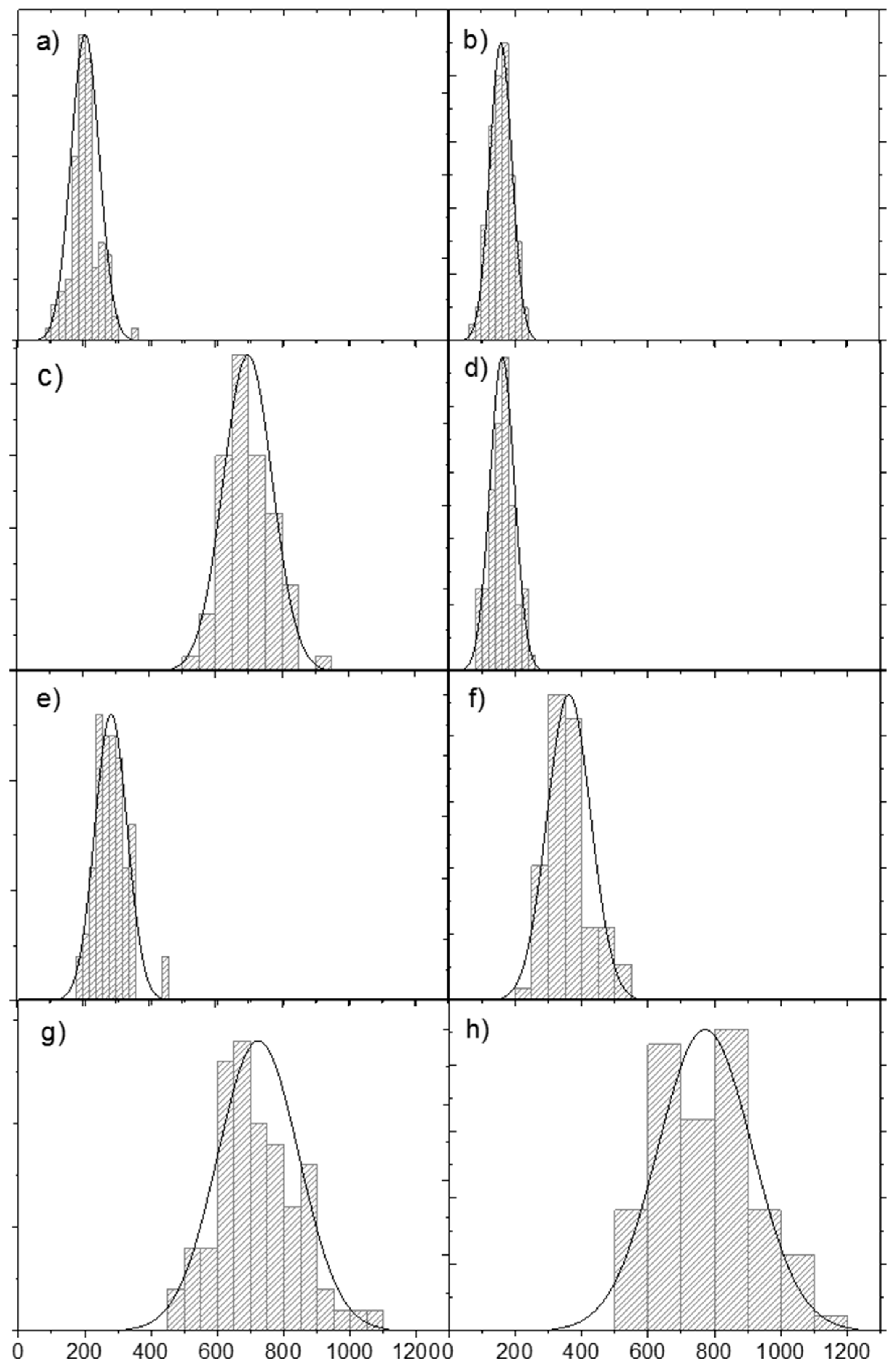
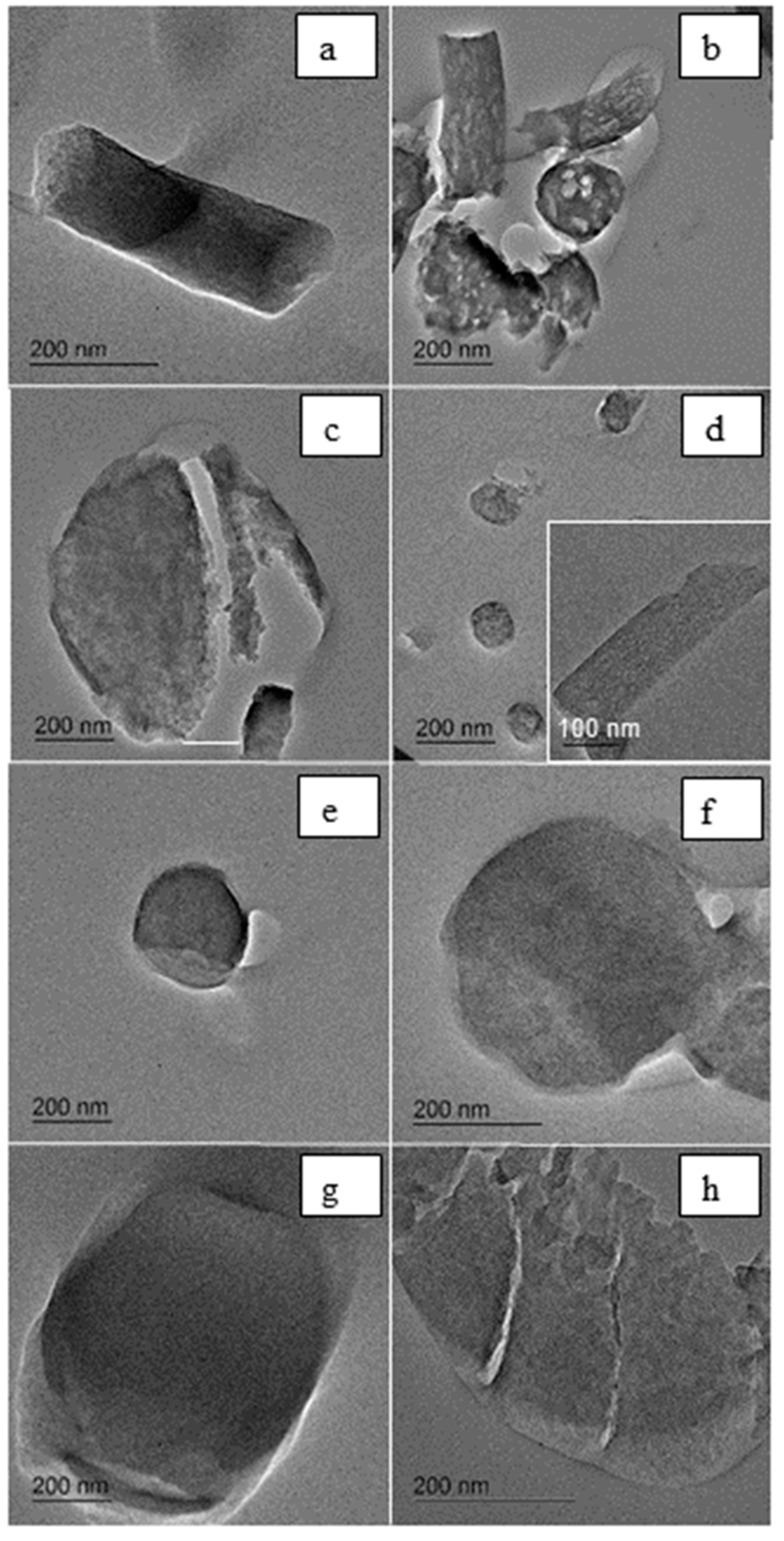
3.1. Characterization of Porogen-PAN Fibrous Webs After Carbonization in Ar

As a reference, the CNF web prepared only from PAN was characterized (labelled PAN10-CNF). The resulting CNF web was self-standing and flexible, as already reported by the authors [10]. The morphology of PAN10-CNF was investigated by SEM and TEM. The material was observed to be randomly oriented cylindrical fibers (Figure 1a) with an average diameter of 200 nm (Figure 2a). These fibers were smooth and dense, as demonstrated by the TEM cross-section in Figure 3a. According to the latter image and to previous reports [47], the porosity and specific surface area developed by such fibers is very low (ca 20 m2·g−1), mainly attributed to the outer surface area of the fibers, with no internal porosity. The nearly flat N2 adsorption isotherm demonstrates the lack of porosity inside the fibers (Figure 4).
In order to create internal porosity within fibers, a range of porogens were added to the precursor PAN solution prior to electrospinning, as described in the experimental methods. The investigated polymer templates (PMMA, PVP, Nafion®) were selected for their relative stability and rigidity. They are known to be stable up to 250 °C in air, the conditions used during the stabilization step. When heated to much higher temperatures in inert gas, they decompose and form mainly volatile products, thereby acting as porogens, while PAN decomposes as well but is converted to carbon in high yield.
The results obtained with PMMA are discussed first. PMMA of two different molecular weights (15,000 and 120,000 g·mol−1) and in different ratios to PAN (1:4 and 2:3) was added in the electrospun DMF-based solution. Those ratios were selected on the basis of a previous study on PMMA-PAN composite fibers [36]. In all the cases, the addition of PMMA resulted in CNFs with slightly smaller average diameter (compare Figure 1a,b) than for the reference PAN10-CNF web (average diameter of 175 nm, see Figure 2b), but with otherwise practically identical features and properties (Figure S1). Figure 1b depicts the sample 15kPMMA2-PAN8-CNF as an example. The decrease in fiber diameter is most probably due to the lower concentration of PAN in the electrospun solution relative to the reference PAN10-CNF (8% vs. 10%), and was also expected due to the change in precursor viscosity already observed upon addition of this polymer [6]. The developed porosity is clearly visible on the cross-sectional TEM micrograph (Figure 3b), where pores with an average diameter of 10 nm appeared within the fibers. The modification of the preparation parameters (higher molecular weight for PMMA, or different PMMA:PAN ratio) did not have significant effects on the obtained morphology and porosity (images not shown). The question as to whether the formed porosity is open or closed is discussed later.
The results obtained with PVP porogen are now discussed. A PVP:PAN ratio of 1:2 was employed (sample labelled PVP5-PAN10-CNF). In these conditions, carbon fibers with considerably greater diameter compared to the reference PAN10-CNF (average diameter of 750 nm) (Figure 1c and Figure 2c) were obtained. This can be attributed to a modification of the viscosity of the electrospun solution, affected by the presence of PVP aggregates and consequent decrease in chain entanglement. The pores generated inside the CNFs presented an average size around 3 nm (Figure 3c).
The third polymer template investigated was Nafion® perfluorosulfonic acid. It has been previously demonstrated to be effective in creating nanoscale porous domains inside carbon nanofibers [34]. In this work, its addition to PAN (sample labelled Nafion2-PAN8-CNF) resulted in the formation of thin carbon fibers (average fiber diameter of 180 nm) (Figure 1d and Figure 2d). The CNF webs also had an obviously a higher density of fibers (compare Figure 1a,d), which is beneficial for improved conductivity and mechanical stability. The fibers have a well-developed internal porosity, as shown by TEM analysis of the cross-sections, Figure 3d. A homogeneous distribution of pores with a size of 4 nm can be observed within the CNF structure.
Finally, the inorganic template precursor ZnCl2 was investigated. The presence of ZnCl2 may allow the formation of pores during the ensuing stabilization-carbonization steps in air and in Ar with the following mechanism: during the stabilization step, hydrated chloride hydrolyzes and forms an oxychloride, from which zinc oxide forms creating microporosity by etching carbon atoms [23]. FE-SEM characterization of Figure 1e–h showed that increasing the ZnCl2 concentration in the electrospun solution from 1 wt % to 7 wt % (samples Zn1-PAN10-CNF, Zn3-PAN10-CNF, Zn5-PAN10-CNF, Zn7-PAN10-CNF) the diameter of the carbon fibers increased tremendously from 300 to 700 nm (Figure 2e–h). It is known that solution conductivity affects fiber uniformity. The high conductivity of the PAN/ZnCl2 (52:1) solution was reported to lead to instability in the electrospinning process with the formation of large fibers and bundles as a cotton-like 3D deposit [48]. However, the reverse has also been observed: increasing the conductivity through the addition of salt may produce finer, more uniform fibers, resulting in an increased elongational force exerted on the fiber jet [49]. Indeed, other reports on the electrospinning of ZnCl2/PAN solutions showed that the average diameters of the obtained CNFs gradually decrease from 350 to 200 nm with increasing zinc chloride content from 1 wt % to 5 wt % [23].
Another particular feature of CNFs derived from electrospun ZnCl2/PAN solutions is the formation of progressively larger fiber bundles with increased Zn salt concentration (see Figure 1g,h in particular). This phenomenon was already observed for PAN/polystyrene mixtures, where the template not only acted as sacrificial decomposable phase, but also controlled the formation of these architectures [13]. In the TEM micrographs of the cross-sections of Zn1-PAN10-CNF, Zn3-PAN10-CNF, Zn5-PAN10-CNF, Zn7-PAN10-CNF samples (Figure 3e–h), no pores are visible inside the fibers.
Except for the latter Zn-PAN-CNF samples, all other CNFs derived from polymer/PAN solutions containing the sacrificial polymers presented pores visible by TEM in the mesoscopic range, in agreement with previous works [6,14,29,30,34]. The nitrogen adsorption/desorption isotherms of all the investigated CNFs showed however very low SBET values (below 20 m2·g−1, see * in column 2 of Table 2), almost unchanged compared to the reference PAN-CNFs (Table 2). This result, apparently in contrast with the micrographs of Figure 3 showing pores of different size in the prepared CNFs and in contrast with previous reports using the same templates and similar synthesis conditions [6,14,28,29,30,34], demonstrates that the obtained porosity is closed, and not accessible from outside the CNFs. This observation may be due to the partial collapse of the percolating porous network formed during the thermal removal of the template or porogen [34]. As a result, free-standing porous fiber webs are obtained, with closed porosity and low surface area. The latter is assigned only to the outer surface area of plain and smooth CNFs with diameters in the range 150–700 nm, depending on the porogen used. The appealing approach of using a soft or hard template added during the preparation step of electrospinning seems therefore ineffective in creating open porosity. The conditions necessary to reach an open porosity are shown later in this study.
Graphitic character and the related electrical conductivity of the carbon based electrode materials are relevant properties for electrochemical applications. To investigate them, Raman spectroscopy and the four-electrode method were used to characterize the carbon nanofiber networks prepared in this work. In particular, the modification of this properties upon the different steps of preparation was studied. The Raman spectra of all CNFs prepared with different porogens (Figure S2) present two intense and broad bands, the so-called D band at 1357 cm−1 ascribed to defects and disorder in the graphitic structure and the so-called G band at 1560 cm−1 corresponding to the in-plane vibration of sp2-bonded carbon in graphite. The spectra were fitted with more contributions, namely the D4 band, ascribed to sp3-carbon (1180 cm−1), the D3 band (1500 cm−1) associated with an amorphous sp2 carbon bonded in the graphitic phase and the D2 band (1580 cm−1) corresponding to graphitic lattices in the structure (Figure S3) [50]. The relative intensities of the D and G bands (ID/IG) as well as the relative areas (AD/AG) are often used to estimate the degree of graphitization of carbon materials [39,51]. Lower ID/IG ratios indicate higher levels of crystalline sp2-carbon [52,53]. The ID/IG and AD/AG values obtained after deconvolution of the spectra of all CNFs derived from the carbonization of porogen/PAN solutions are summarized in Table 3. It is evident that the addition of polymer or inorganic salt porogen did not significantly influence the graphitization of the carbon fibers. Similar ID/IG ratios were obtained for reference PAN10-CNFs and the other CNF webs. Their values between 1.8 and 2.7 demonstrate that the fibers are composed by disordered carbon (due to the relatively low carbonization temperature of 1000 °C) with local graphite inclusions (turbostratic domains) already evidenced for electrospun CNFs [24,39,47,54].
The electrical conductivities of the CNFs prepared by electrospinning, determined directly on the self-standing CNF webs, are consistent with the partial graphitic character evidenced by Raman spectroscopy. Except for the fibers prepared using zinc chloride as porogen precursor, which show significantly lower conductivity, all CNF networks present similar conductivity values around 6–9 S·cm−1 (Table 4), which is in agreement with previous results obtained on PAN based electrospun materials [10,47,55].
The carbon fibers prepared from ZnCl2-PAN10 fibers demonstrated very low conductivity, between 3.3 and 0.8 S·cm−1. The graphitic structure being the same for all the samples as indicated by the Raman study, this decrease in conductivity from the pristine CNFs may be ascribed to the microstructure of the ZnCl2-PAN-CNFs in which, due to ZnCl2 removal, electron paths are likely disrupted. Furthermore, its particular morphology with fibers forming large bundles can affect the inter-fiber/inter-bundle connection (decreased number of connection points) and thus the electron transport.

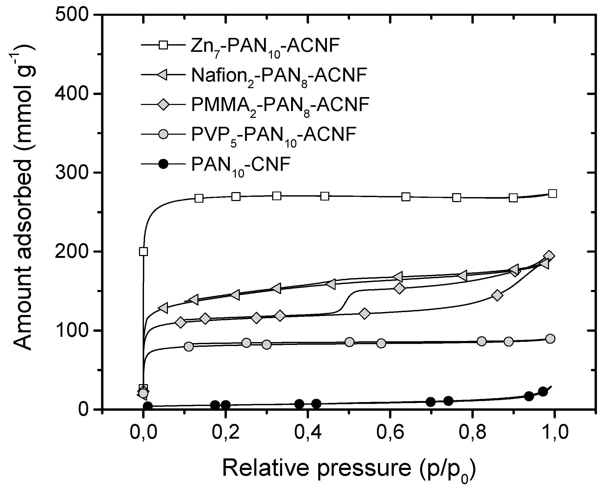
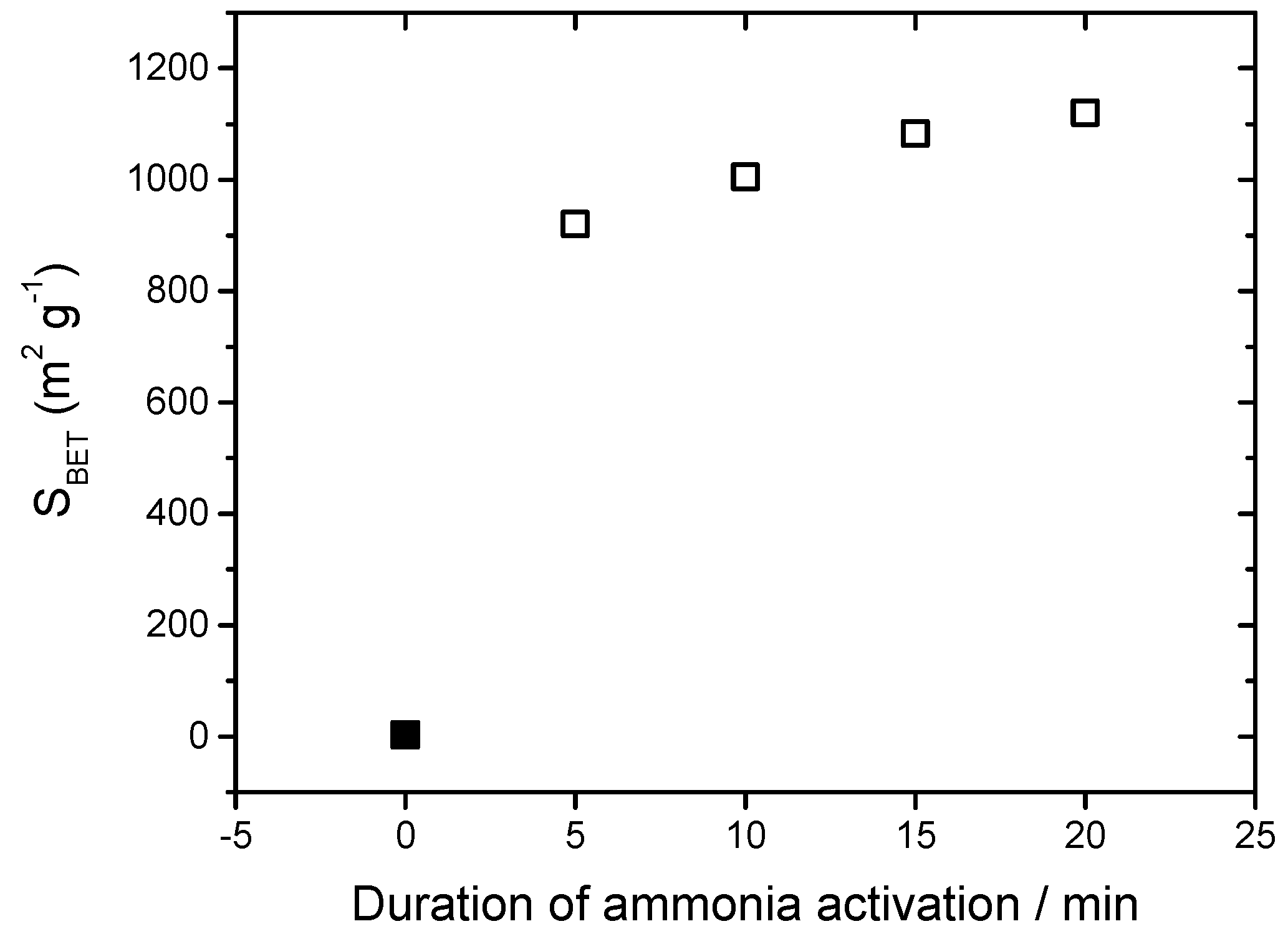
3.2. Characterization of Porogen-PAN Fibrous Webs After Carbonization and NH3 Activation

The post-treatment with ammonia at high temperature is a conventional approach to creating porosity in carbon-based materials by etching, which can also introduce nitrogen functionalities on the surface [56]. The mechanism for the formation of both pores and nitrogen groups is based on the reaction of ammonia with carbon. This gasification reaction continuously occurs during NH3 pyrolysis and react with surface carbon atoms forming volatile compounds such as HCN [57,58]. When the reaction between ammonia and carbon occurs at different rates on the surface (due to carbon structure heterogeneity), increased porosity is obtained. When the ammonia pyrolysis is stopped, nitrogen atoms that were reacting with carbon surface atoms at that moment remain on the surface, with different environments including amino, cyanide, pyrrolic, pyridinic and quaternary nitrogen groups [59,60].
We first subjected the reference electrospun carbon nanofibers PAN10-CNF web to treatment under pure flowing ammonia at 900 °C [61]. The resulting activated nanofibers (ACNFs), labelled PAN10-ACNFs, did not present significant modification of their average diameter (200 nm) nor of their porosity, still not visible by TEM cross-sectional observations (Figure S4). As a consequence, specific surface area determined from nitrogen adsorption/desorption isotherms remained low (Table 2). Due to the low surface area obtained with the porogen/PAN template method after carbonization in Ar, as described previously, and the low surface area obtained with ammonia activation on pure PAN-derived CNFs, the combination of the two approaches was then investigated as a last attempt to develop high specific area. All CNF webs that had been prepared by porogen/PAN templating and carbonized in Ar (labelled CNF) were then further activated in flowing ammonia gas in the same conditions as for PAN10-ACNF.
N2 adsorption-desorption measurements were performed to characterize their porosity and specific surface area (Table 2 and Figure 4). Figure 4 clearly shows that ACNF webs adsorbed a significant amount of N2, the three polymer porogens resulting in intermediate adsorbed volumes and the ZnCl2 porogen resulting in the highest adsorbed volumes. The isotherms of the different ACNF webs are of type I and/or type II according to IUPAC classification, which indicates that fibers presented an overall microporous structure, as well as mesopores. With Nafion® as a porogen, significant hysteresis of type H4 is observed during desorption, closing at P/P0 = 0.45. This is assigned to mesopores with a bottleneck shape, which may be related to the existence of Nafion® polymer aggregates in the electrospinning solution [62,63], while other polymers were fully dissolved. In the case of microporous structures, the BET energetic constant (CBET, related to the energy of adsorption of the first layer of N2 adsorbate on the carbon surface) is expected to be higher than the usual value expected for mesoporous carbon structure as seen in Table 2 [64]. The values of the specific surface area, meso and micropore volume as well as average pore diameter of all ACNF webs are summarized in Table 2. The specific surface area of all ACNF webs ranged from 325 to 1083 m2·g−1, the maximum value corresponding to ZnCl7-PAN10-ACNF, while the average pore size was comprised between 0.5 and 2.9 nm.
The carbon fibers derived from PMMA-PAN solutions presented surface areas between 360 and 645 m2·g−1. The specific area increased by increasing the molecular weight of the sacrificial polymer from 15,000 to 120,000 g·mol−1 and by decreasing the PMMA:PAN ratio from 2:3 to 1:4. The carbon fibers derived from the PVP-PAN solution with a PVP:PAN ratio of 1:2 presented a surface area of 325 m2·g−1. This is comparable to the BET value obtained with PMMA in high ratio to PAN (2:3), and may also be increased if the PVP:PAN ratio had been further optimized (lowered). The carbon fibers derived from Nafion®-PAN solution with Nafion®:PAN ratio of 1:4 presented a surface area of 535 m2·g−1, also comparable to the SBET value obtained with PMMA:PAN ratio of 1:4 (450 m2·g−1 and 645 m2·g−1, depending on PMMA molecular weight). The carbon fibers obtained from ZnCl2-PAN solutions showed a SBET value of 680 m2·g−1 already at a low ZnCl2:PAN ratio of 1:10, further increasing with increasing amounts of ZnCl2: PAN ratio from 3:10 to 7:10. Due to the high value of 1083 m2·g−1 measured for the carbon fibers obtained using a ZnCl2:PAN ratio of 7:10 and for the regular ammonia activation duration of 15 min at 900 °C, the effect of the duration of activation was performed for this sample, at the same temperature of 900 °C. It is noted that the ammonia pyrolysis was performed in flash mode [65], (sample heated from room temperature to 900 °C in the range of 1–1.5 min), which allows very precise control of the pyrolysis duration down to 5 min. To stop the pyrolysis, the quartz tube was immediately removed from the split hinge oven. The results are depicted in Figure 5. The specific area was already high after only 5 min of ammonia activation, with slightly increased values for increased durations up to 20 min. The optimal duration was considered to be 15 min, corresponding to the maximum compromise between high developed area and high mechanical resistance. A longer treatment of 20 min led to an increased fragility of the carbon web, limiting its utilization as a self-standing electrode.
Raman spectra recorded on activated fibrous webs were very similar to those obtained with carbonized samples (Figure S5). The calculated ID/IG ratios (Table 3) were practically unchanged upon activation in ammonia, demonstrating that the degree of graphitization was not significantly impacted by the etching treatment.
As already mentioned, ammonia activation usually leads to (additional) nitrogen doping of the carbon [56,59]. In order to evaluate the introduction of nitrogen sites in the prepared ACNF webs, elemental analysis was performed before and after the NH3 treatment, for selected CNF webs (Table 4). The nitrogen amount in the CNF derived from PAN only was around 5.6 wt % after carbonization (PAN10 row in Table 4, CNF column), in agreement with previous reports and with the carbonization temperature of 900 °C. It is known that higher pyrolysis temperatures result in lower nitrogen content [15]. For the reference PAN10-CNF, the nitrogen amount slightly increased to 7.0% after ammonia activation, while a decrease in O wt % was observed. The latter effect is explained by selective etching of surface O-containing groups by ammonia. For PVP5-PAN10 and Zn7-PAN10, an approximately three-fold increase in nitrogen amount was observed from CNF to ACNF webs, accompanied by a reduction in O wt % [59]. All ACNF webs however had comparable N wt % amounts, in the range of 6.1 to 7.0 wt %.
Nitrogen doping, in particular with ammonia (highly basic nitrogen groups), is interesting for some electrochemical applications such as supercapacitors or oxygen-reducing sites (in alkaline electrolytes in particular). The etching of some carbon masses during ammonia activation results in carbon fibers with increased internal porosity and also possibly weakened inter-fiber connections, which may impact the mechanical stability of self-standing fiber webs and also their electrical conductivity. The electrical conductivity of selected carbon fiber webs (one selected for each type of porogen) was halved after the ammonia activation (Table 4). For example, it dropped from 6.6 to 3.8 S·cm−1 for the reference web derived from PAN only, and from 9.7 to 4.8 S·cm−1 for PVP5-PAN10-CNF and PVP5-PAN10-ACNF, respectively. Interestingly, the fact that the conductivity decreased significantly even for PAN10-ACNF while such fibers have no open porosity, indicates that the decreased in-plane conductivity cannot be assigned to the formation of open pores in the fibers. The decreased conductivity of carbon fiber webs after ammonia activation may be due to the nitrogen doping itself (decreasing the intrinsic conductivity of carbon) or weakened electrical contact at the nodes of the fibrous web (possibly due to etching of carbon at the nodes). As already mentioned earlier for the series of Zn7-PAN10-CNF fibers subjected to various duration of activation in ammonia, activation longer than 20 min still resulted in a self-standing web but with greatly increased fragility, which is directly related to the quality of the nodes of the webs.
All these results lead to the conclusion that the open porosity in the PAN-derived CNFs resulted from a two-step approach involving the combination of a template route with a chemical activation step. The porogens incorporated in the electrospun PAN solution led first to carbon fibers with closed pores after the carbonization in Ar. The closed pores could be opened and interconnected within the fiber upon a post-treatment in ammonia atmosphere at high temperature. Other examples of etching in combination with the use of porogens have been reported (e.g., water etching-assisted templating) [31].
The purpose of this work was the rationalization of an effective strategy to obtain CNF webs with both high porosity between fibers and high specific area by introducing porosity inside the fibers for application in electrochemical energy conversion and storage devices. Having this objective in mind, it is also important to maintain the electrical conductivity of the self-standing CNF webs to sufficiently high values. Typically, to be not be limited by the conduction of electrons across an electrode, the electric conductivity must be about 100 times higher than the electrolyte conductivity. The results indicate that the approach combining the introduction of templates and chemical activation led to open micro- and mesoporosity inside the fibers, while the electric conductivity was approximately halved during the ammonia activation step. This decrease in conductivity may be due to the removal of a fraction of the carbon from the bulk of the CNFs during ammonia activation and/or the fragilization of the interfibrous connection. In addition, when the electrical conductivity of self-standing CNF ammonia-activated webs is plotted against their BET area, a negative linear correlation is observed (Figure 6). The identification of such a correlation is useful to select the best compromise between conductivity and BET area, which will depend on the exact electrochemical application and range of typical current densities produced by an electrode (in the order of increasing current density: batteries < fuel cells < supercapacitors). With current densities <10 mA·cm−2, the reported conductivities [66] are not a limiting factor in batteries, and thus any of the ACNF webs could be selected. With current densities in the range of 1–2 A·cm−2, fuel cells are more demanding in terms of electron conductivity in the electrodes. By comparison, the effective proton conductivity in typical active layer of PEMFC is only in the range of 1–2 S·m−1. Therefore, if the electronic conductivity through the active layer is >20 S·m−1 (0.2 S·cm−1), it should not be a factor limiting the porous electrode performance [67,68,69,70]. All present ACNF webs could therefore be applicable for self-standing electrodes in, e.g., PEMFCs. Lastly, in electrochemical supercapacitors the instantaneous current density can reach extremely high values on the order of 10 A·cm−2 due to the non-faradaic process resulting in higher electric conductivity requirements. Moreover, the high electric conductivity requirement is accompanied by the high BET area requirement [71], which are shown in Figure 6 to be antagonistic.

4. Conclusions

  • The templating approach of PAN fibers with polymer or inorganic porogens (PMMA, Nafion®, PVP, ZnCl2) resulted in CNFs with closed porosity after carbonization in Ar.
  • Subsequent activation in ammonia at 900 °C opened this porosity, resulting in specific surface area in the range of 325–1083 m2·g−1.
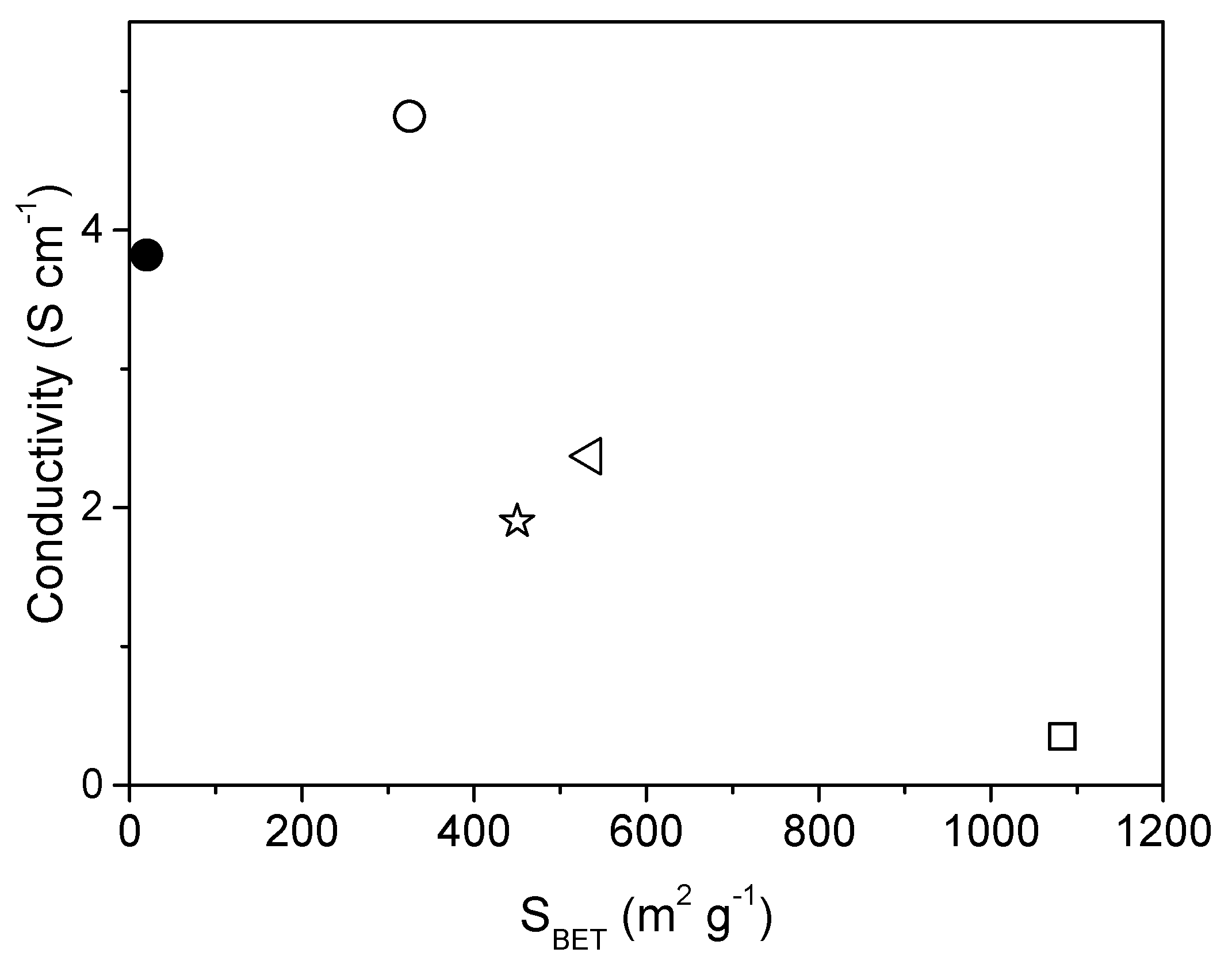
  • Ammonia activation systematically decreased the electric conductivity of the ACNF webs by a factor of approximately two to three.
  • A negative linear correlation between electric conductivity of ammonia-activated ACNF webs and their BET area is revealed.

Supplementary Materials

The following are available online at https://www.mdpi.com/2571-9637/2/1/13/s1, Figure S1. TEM micrographs of PAN CNFs prepared from PAN and PMMA after carbonization and activation; Figure S2. Raman spectra of template based CNFs after carbonization; Figure S3. Example of deconvolution of a Raman spectrum of CNFs (PAN10-CNF) by using Gaussian and Lorentzian curves (Voigt); Figure S4. FE-SEM (left side) and cross-section TEM (right side) micrographs of PAN10-ACNF fibers; Figure S5. Raman spectra of CNFs after activation.

Author Contributions

Conceptualization, S.C and F.J.; methodology, S.C., F.J. and D.J.; formal analysis, S.Y.; investigation, S.Y.; resources, S.C., F.J. and D.J.; writing—original draft preparation, S.Y and S.C.; writing—review and editing, F.J and D.J.; supervision, S.C and F.J.; project administration, F.J.; funding acquisition, F.J. and S.C.

Funding

The research leading to these results has received funding from the French National Research Agency under the CAT2CAT contract (ANR-16-CE05-0007). SC acknowledges the financial support from the European Research Council under the European Union’s Seventh Framework Programme (FP/2007-2013) / ERC Grant Agreement n. 306682 and the French IUF.

Acknowledgments

Authors thank Nicolas Donzel for his help with nitrogen adsorption/desorption analysis and electrical conductivity measurements.

Conflicts of Interest

The authors declare no conflict of interest.

References

  1. Aricò, A.S.; Bruce, P.; Scrosati, B.; Tarascon, J.-M.; van Schalkwijk, W. Nanostructured materials for advanced energy conversion and storage devices. Nat. Mater. 2005, 4, 366–377. [Google Scholar] [CrossRef] [PubMed]
  2. Du, L.; Shao, Y.; Sun, J.; Yin, G.; Liu, J.; Wang, Y. Advanced catalyst supports for PEM fuel cell cathodes. Nano Energy 2016, 29, 314–322. [Google Scholar] [CrossRef]
  3. Cavaliere, S.; Subianto, S.; Savych, I.; Jones, D.J.; Rozière, J. Electrospinning: Designed architectures for energy conversion and storage devices. Energy Environ. Sci. 2011, 4, 4761–4785. [Google Scholar] [CrossRef]
  4. Peng, S.; Li, L.; Kong Yoong, J.L.; Tian, L.; Srinivasan, M.; Adams, S.; Ramakrishna, S. Electrospun carbon nanofibers and their hybrid composites as advanced materials for energy conversion and storage. Nano Energy 2016, 22, 361–395. [Google Scholar] [CrossRef]
  5. Liu, Y.; Fan, L.Z.; Jiao, L. Graphene highly scattered in porous carbon nanofibers: A binder-free and high-performance anode for sodium-ion batteries. J. Mater. Chem. A 2017, 5, 1698–1705. [Google Scholar] [CrossRef]
  6. Peng, Y.; Lo, C. Electrospun porous carbon nanofibers as lithium ion battery anodes. J. Solid State Electrochem. 2015, 19, 3401–3410. [Google Scholar] [CrossRef]
  7. Li, X.; Zhao, Y.; Bai, Y.; Zhao, X.; Wang, R.; Huang, Y.; Liang, Q.; Huang, Z. A Non-Woven Network of Porous Nitrogen-doping Carbon Nanofibers as a Binder-free Electrode for Supercapacitors. Electrochim. Acta 2017, 230, 445–453. [Google Scholar] [CrossRef]
  8. Gopalakrishnan, A.; Sahatiya, P.; Badhulika, S. Template-Assisted Electrospinning of Bubbled Carbon Nanofibers as Binder-Free Electrodes for High-Performance Supercapacitors. ChemElectroChem 2018, 5, 531–539. [Google Scholar] [CrossRef]
  9. Liu, D.; Zhang, X.; Sun, Z.; You, T. Free-standing nitrogen-doped carbon nanofiber films as highly efficient electrocatalysts for oxygen reduction. Nanoscale 2013, 5, 9528–9531. [Google Scholar] [CrossRef] [PubMed]
  10. Ercolano, G.; Farina, F.; Cavaliere, S.; Jones, D.J.; Rozière, J. Towards ultrathin Pt films on nanofibres by surface-limited electrodeposition for electrocatalytic applications. J. Mater. Chem. A 2017, 5, 3974–3980. [Google Scholar] [CrossRef]
  11. Kayarkatte, M.K.; Delikaya, Ö.; Roth, C. Freestanding Catalyst Layers: A Novel Electrode Fabrication Technique for PEM Fuel Cells via Electrospinning. ChemElectroChem 2017, 4, 404–411. [Google Scholar] [CrossRef]
  12. Chan, S.; Jankovic, J.; Susac, D.; Saha, M.S.; Tam, M.; Yang, H.; Ko, F. Electrospun carbon nanofiber catalyst layers for polymer electrolyte membrane fuel cells: Structure and performance. J. Power Sources 2018, 392, 239–250. [Google Scholar] [CrossRef]
  13. Sun, J.; Zeng, L.; Jiang, H.R.; Chao, C.Y.H.; Zhao, T.S. Formation of electrodes by self-assembling porous carbon fibers into bundles for vanadium redox flow batteries. J. Power Sources 2018, 405, 106–113. [Google Scholar] [CrossRef]
  14. Cao, Y.; Lu, H.; Hong, Q.; Bai, J.; Wang, J.; Li, X. Co decorated N-doped porous carbon nanofibers as a free-standing cathode for Li-O2 battery: Emphasis on seamlessly continuously hierarchical 3D nano-architecture networks. J. Power Sources 2017, 368, 78–87. [Google Scholar] [CrossRef]
  15. Liu, C.-K.; Lai, K.; Liu, W.; Yao, M.; Sun, R.-J. Preparation of carbon nanofibres through electrospinning and thermal treatment. Polym. Int. 2009, 58, 1341–1349. [Google Scholar] [CrossRef]
  16. Nan, D.; Wang, J.-G.; Huang, Z.-H.; Wang, L.; Shen, W.; Kang, F. Highly porous carbon nanofibers from electrospun polyimide/SiO2 hybrids as an improved anode for lithium-ion batteries. Electrochem. Commun. 2013, 34, 52–55. [Google Scholar] [CrossRef]
  17. Zhang, L.; Jiang, Y.; Wang, L.; Zhang, C.; Liu, S. Hierarchical porous carbon nanofibers as binder-free electrode for high-performance supercapacitor. Electrochim. Acta 2016, 196, 189–196. [Google Scholar] [CrossRef]
  18. Alothman, Z.A. A review: Fundamental aspects of silicate mesoporous materials. Materials 2012, 5, 2874–2902. [Google Scholar] [CrossRef]
  19. Ma, C.; Cao, E.; Li, J.; Fan, Q.; Wu, L.; Song, Y.; Shi, J. Synthesis of mesoporous ribbon-shaped graphitic carbon nanofibers with superior performance as efficient supercapacitor electrodes. Electrochim. Acta 2018, 292, 364–373. [Google Scholar] [CrossRef]
  20. Chen, Y.; Lu, Z.; Zhou, L.; Mai, Y.-W.; Huang, H. In situ formation of hollow graphitic carbon nanospheres in electrospun amorphous carbon nanofibers for high-performance Li-based batteries. Nanoscale 2012, 4, 6800. [Google Scholar] [CrossRef] [PubMed]
  21. Xie, W.; Khan, S.; Rojas, O.J.; Parsons, G.N. Control of Micro- and Mesopores in Carbon Nanofibers and Hollow Carbon Nanofibers Derived from Cellulose Diacetate via Vapor Phase Infiltration of Diethyl Zinc. ACS Sustain. Chem. Eng. 2018, 6, 13844–13853. [Google Scholar] [CrossRef]
  22. Ma, C.; Li, Z.; Li, J.; Fan, Q.; Wu, L.; Shi, J.; Song, Y. Lignin-based hierarchical porous carbon nanofiber films with superior performance in supercapacitors. Appl. Surf. Sci. 2018, 456, 568–576. [Google Scholar] [CrossRef]
  23. Kim, C.; Ngoc, B.T.N.; Yang, K.S.; Kojima, M.; Kim, Y.A.; Kim, Y.J.; Endo, M.; Yang, S.C. Self-Sustained Thin Webs Consisting of Porous Carbon Nanofibers for Supercapacitors via the Electrospinning of Polyacrylonitrile Solutions Containing Zinc Chloride. Adv. Mater. 2007, 19, 2341–2346. [Google Scholar] [CrossRef]
  24. Yin, D.; Han, C.; Bo, X.; Liu, J.; Guo, L. Prussian blue analogues derived iron-cobalt alloy embedded in nitrogen-doped porous carbon nanofibers for efficient oxygen reduction reaction in both alkaline and acidic solutions. J. Colloid Interface Sci. 2019, 533, 578–587. [Google Scholar] [CrossRef] [PubMed]
  25. Zhang, W.; Yao, X.; Zhou, S.; Li, X.; Li, L.; Yu, Z.; Gu, L. ZIF-8/ZIF-67-Derived Co-Nx-Embedded 1D Porous Carbon Nanofibers with Graphitic Carbon-Encased Co Nanoparticles as an Efficient Bifunctional Electrocatalyst. Small 2018, 14, 1800423. [Google Scholar] [CrossRef] [PubMed]
  26. Yao, Y.; Liu, P.; Li, X.; Zeng, S.; Lan, T.; Huang, H.; Zeng, X.; Zou, J. Nitrogen-doped graphitic hierarchically porous carbon nanofibers obtained: Via bimetallic-coordination organic framework modification and their application in supercapacitors. Dalton Trans. 2018, 47, 7316–7326. [Google Scholar] [CrossRef] [PubMed]
  27. Wang, C.; Kaneti, Y.V.; Bando, Y.; Lin, J.; Liu, C.; Li, J.; Yamauchi, Y. Metal-organic framework-derived one-dimensional porous or hollow carbon-based nanofibers for energy storage and conversion. Mater. Horiz. 2018, 5, 394–407. [Google Scholar] [CrossRef]
  28. Zhang, W.; Miao, W.; Liu, X.; Li, L.; Yu, Z.; Zhang, Q. High-rate and ultralong-stable potassium-ion batteries based on antimony-nanoparticles encapsulated in nitrogen and phosphorus co-doped mesoporous carbon nanofibers as an anode material. J. Alloys Compd. 2018, 769, 141–148. [Google Scholar] [CrossRef]
  29. Jeong, J.; Choun, M.; Lee, J. Tree-Bark-Shaped N-Doped Porous Carbon Anode for Hydrazine Fuel Cells. Angew. Chem. Int. Ed. 2017, 56, 13513–13516. [Google Scholar] [CrossRef] [PubMed]
  30. Zhao, X.; Xiong, P.; Meng, J.; Liang, Y.; Wang, J.; Xu, Y. High rate and long cycle life porous carbon nanofiber paper anodes for potassium-ion batteries. J. Mater. Chem. A 2017, 5, 19237–19244. [Google Scholar] [CrossRef]
  31. An, G.-H.; Koo, B.-R.; Ahn, H.-J. Activated mesoporous carbon nanofibers fabricated using water etching-assisted templating for high-performance electrochemical capacitors. Phys. Chem. Chem. Phys. 2016, 18, 6587–6594. [Google Scholar] [CrossRef] [PubMed]
  32. He, T.; Fu, Y.; Meng, X.; Yu, X.; Wang, X. A novel strategy for the high performance supercapacitor based on polyacrylonitrile-derived porous nanofibers as electrode and separator in ionic liquid electrolyte. Electrochim. Acta 2018, 282, 97–104. [Google Scholar] [CrossRef]
  33. Yang, D.S.; Chaudhari, S.; Rajesh, K.P.; Yu, J.S. Preparation of nitrogen-doped porous carbon nanofibers and the effect of porosity, electrical conductivity, and nitrogen content on their oxygen reduction performance. ChemCatChem 2014, 6, 1236–1244. [Google Scholar] [CrossRef]
  34. Tran, C.; Kalra, V. Fabrication of porous carbon nanofibers with adjustable pore sizes as electrodes for supercapacitors. J. Power Sources 2013, 235, 289–296. [Google Scholar] [CrossRef]
  35. Wang, W.; Wang, H.; Wang, H.; Jin, X.; Li, J.; Zhu, Z. Electrospinning preparation of a large surface area, hierarchically porous, and interconnected carbon nanofibrous network using polysulfone as a sacrificial polymer for high performance supercapacitors. RSC Adv. 2018, 8, 28480–28486. [Google Scholar] [CrossRef]
  36. Liu, J.; Xiong, Z.; Wang, S.; Cai, W.; Yang, J.; Zhang, H. Structure and electrochemistry comparison of electrospun porous carbon nanofibers for capacitive deionization. Electrochim. Acta 2016, 210, 171–180. [Google Scholar] [CrossRef]
  37. Ji, L.; Zhang, X. Fabrication of porous carbon nanofibers and their application as anode materials for rechargeable lithium-ion batteries. Nanotechnology 2009, 20, 155705. [Google Scholar] [CrossRef] [PubMed]
  38. Zhang, H.; Xie, Z.; Wang, Y.; Shang, X.; Nie, P.; Liu, J. Electrospun polyacrylonitrile/β-cyclodextrin based porous carbon nanofiber self-supporting electrode for capacitive deionization. RSC Adv. 2017, 7, 55224–55231. [Google Scholar] [CrossRef] [Green Version]
  39. Le, T.H.; Tian, H.; Cheng, J.; Huang, Z.H.; Kang, F.; Yang, Y. High performance lithium-ion capacitors based on scalable surface carved multi hierarchical construction electrospun carbon fibers. Carbon N. Y. 2018, 138, 325–336. [Google Scholar] [CrossRef]
  40. Heo, Y.-J.; Lee, H.I.; Lee, J.W.; Park, M.; Rhee, K.Y.; Park, S.-J. Optimization of the pore structure of PAN-based carbon fibers for enhanced supercapacitor performances via electrospinning. Compos. Part B Eng. 2019, 161, 10–17. [Google Scholar] [CrossRef]
  41. Lee, H.-M.; Kim, H.-G.; Kang, S.-J.; Park, S.-J.; An, K.-H.; Kim, B.-J. Effects of pore structures on electrochemical behaviors of polyacrylonitrile (PAN)-based activated carbon nanofibers. J. Ind. Eng. Chem. 2015, 21, 736–740. [Google Scholar] [CrossRef]
  42. Kim, C.H.; Kim, B.-H. Zinc oxide/activated carbon nanofiber composites for high-performance supercapacitor electrodes. J. Power Sources 2015, 274, 512–520. [Google Scholar] [CrossRef]
  43. Kim, C.; Yang, K.S. Electrochemical properties of carbon nanofiber web as an electrode for supercapacitor prepared by electrospinning. Appl. Phys. Lett. 2003, 83, 1216–1218. [Google Scholar] [CrossRef]
  44. Zhang, T.; Xiao, B.; Zhou, P.; Xia, L.; Wen, G.; Zhang, H. Porous-carbon-nanotube decorated carbon nanofibers with effective microwave absorption properties. Nanotechnology 2017, 28, 355708. [Google Scholar] [CrossRef] [PubMed]
  45. Fitzer, E.; Frohs, W.; Heine, M. Optimization of stabilization and carbonization treatment of PAN fibres and structural characterization of the resulting carbon fibres. Carbon N. Y. 1986, 24, 387–395. [Google Scholar] [CrossRef]
  46. Moon, S.; Farris, R.J. Strong electrospun nanometer-diameter polyacrylonitrile carbon fiber yarns. Carbon N. Y. 2009, 47, 2829–2839. [Google Scholar] [CrossRef]
  47. Savych, I.; Bernard D’Arbigny, J.; Subianto, S.; Cavaliere, S.; Jones, D.J.; Rozière, J. On the effect of non-carbon nanostructured supports on the stability of Pt nanoparticles during voltage cycling: A study of TiO2 nanofibres. J. Power Sources 2014, 257, 147–155. [Google Scholar] [CrossRef]
  48. Heikkila, P. Electrospinning of polyacrylonitrile (PAN) solution: Effect of conductive additive and filler on the process. eXPRESS Polym. Lett. 2009, 3, 437–445. [Google Scholar] [CrossRef] [Green Version]
  49. Subianto, S.; Cornu, D.; Cavaliere, S. Fundamentals of Electrospinning. In Electrospinning for Advanced Energy and Environmental Applications; Cavaliere, S., Ed.; CRC Press: Boca Raton, FL, USA, 2015; pp. 1–27. [Google Scholar]
  50. Karacan, I.; Erzurumluoğlu, L. The effect of carbonization temperature on the structure and properties of carbon fibers prepared from poly(m-phenylene isophthalamide) precursor. Fibers Polym. 2015, 16, 1629–1645. [Google Scholar] [CrossRef]
  51. Shi, R.; Han, C.; Xu, X.; Qin, X.; Xu, L.; Li, H.; Li, J.; Wong, C.P.; Li, B. Electrospun N-Doped Hierarchical Porous Carbon Nanofiber with Improved Degree of Graphitization for High-Performance Lithium Ion Capacitor. Chem. A Eur. J. 2018, 24, 10460–10467. [Google Scholar] [CrossRef] [PubMed]
  52. Cançado, L.G.; Jorio, A.; Ferreira, E.H.M.; Stavale, F.; Achete, C.A.; Capaz, R.B.; Moutinho, M.V.O.; Lombardo, A.; Kulmala, T.S.; Ferrari, A.C. Quantifying Defects in Graphene via Raman Spectroscopy at Different Excitation Energies. Nano Lett. 2011, 11, 3190–3196. [Google Scholar] [CrossRef] [PubMed] [Green Version]
  53. Cançado, L.G.; Gomes da Silva, M.; Martins Ferreira, E.H.; Hof, F.; Kampioti, K.; Huang, K.; Pénicaud, A.; Alberto Achete, C.; Capaz, R.B.; Jorio, A. Disentangling contributions of point and line defects in the Raman spectra of graphene-related materials. 2D Mater. 2017, 4, 025039. [Google Scholar] [CrossRef] [Green Version]
  54. Zhang, Z.; Li, X.; Wang, C.; Fu, S.; Liu, Y.; Shao, C. Polyacrylonitrile and carbon nanofibers with controllable nanoporous structures by electrospinning. Macromol. Mater. Eng. 2009, 294, 673–678. [Google Scholar] [CrossRef]
  55. Inagaki, M.; Yang, Y.; Kang, F. Carbon nanofibers prepared via electrospinning. Adv. Mater. 2012, 24, 2547–2566. [Google Scholar] [CrossRef] [PubMed]
  56. Atamny, F.; Blöcker, J.; Dübotzky, A.; Kurt, H.; Timpe, O.; Loose, G.; Mahdi, W.; Schlögl, R. Surface chemistry of carbon: Activation of molecular oxygen. Mol. Phys. 1992, 76, 851–886. [Google Scholar] [CrossRef]
  57. Jaouen, F.; Serventi, A.M.; Lefèvre, M.; Dodelet, J.; Bertrand, P. Non-Noble Electrocatalysts for O 2 Reduction: How Does Heat Treatment Affect Their Activity and Structure? Part II. Structural Changes Observed by Electron Microscopy, Raman, and Mass Spectroscopy. J. Phys. Chem. C 2007, 111, 5971–5976. [Google Scholar] [CrossRef]
  58. Jaouen, F.; Dodelet, J. Non-Noble Electrocatalysts for O2 Reduction: How Does Heat Treatment Affect Their Activity and Structure? Part I. Model for Carbon Black Gasification by NH 3: Parametric Calibration and Electrochemical Validation. J. Phys. Chem. C 2007, 111, 5963–5970. [Google Scholar] [CrossRef]
  59. Shen, W.; Fan, W. Nitrogen-containing porous carbons: Synthesis and application. J. Mater. Chem. A 2013, 1, 999. [Google Scholar] [CrossRef]
  60. Artyushkova, K.; Kiefer, B.; Halevi, B.; Knop-Gericke, A.; Schlogl, R.; Atanassov, P. Density functional theory calculations of XPS binding energy shift for nitrogen-containing graphene-like structures. Chem. Commun. 2013, 49, 2539. [Google Scholar] [CrossRef] [PubMed] [Green Version]
  61. Nan, D.; Huang, Z.H.; Lv, R.; Yang, L.; Wang, J.G.; Shen, W.; Lin, Y.; Yu, X.; Ye, L.; Sun, H.; et al. Nitrogen-enriched electrospun porous carbon nanofiber networks as high-performance free-standing electrode materials. J. Mater. Chem. A 2014, 2, 19678–19684. [Google Scholar] [CrossRef]
  62. Subianto, S.; Cavaliere, S.; Jones, D.J.; Rozière, J. Effect of side-chain length on the electrospinning of perfluorosulfonic acid ionomers. J. Polym. Sci. Part A Polym. Chem. 2013, 51, 118–128. [Google Scholar] [CrossRef]
  63. Ballengee, J.B.; Pintauro, P.N. Morphological Control of Electrospun Nafion Nanofiber Mats. J. Electrochem. Soc. 2011, 158, B568–B572. [Google Scholar] [CrossRef]
  64. Brunauer, S.; Emmett, P.H.; Teller, E. Adsorption of Gases in Multimolecular Layers. J. Am. Chem. Soc. 1938, 60, 309–319. [Google Scholar] [CrossRef]
  65. Jaouen, F.; Lefèvre, M.; Dodelet, J.-P.; Cai, M. Heat-Treated Fe/N/C Catalysts for O2 Electroreduction: Are Active Sites Hosted in Micropores? J. Phys. Chem. B 2006, 110, 5553–5558. [Google Scholar] [CrossRef] [PubMed]
  66. Fehse, M.; Cavaliere, S.; Lippens, P.E.; Savych, I.; Iadecola, A.; Monconduit, L.; Jones, D.J.; Rozie, J.; Fischer, F.; Tessier, C.; et al. Nb-Doped TiO2 Nanofibers for Lithium Ion Batteries. J. Phys. Chem. C 2013, 117, 13827–13835. [Google Scholar] [CrossRef]
  67. Liu, Y.; Murphy, M.W.; Baker, D.R.; Gu, W.; Ji, C.; Jorne, J.; Gasteiger, H.A. Proton Conduction and Oxygen Reduction Kinetics in PEM Fuel Cell Cathodes: Effects of Ionomer-to-Carbon Ratio and Relative Humidity. J. Electrochem. Soc. 2009, 156, B970. [Google Scholar] [CrossRef]
  68. Liu, Y.; Ji, C.; Gu, W.; Jorne, J.; Gasteiger, H.A. Effects of Catalyst Carbon Support on Proton Conduction and Cathode Performance in PEM Fuel Cells. J. Electrochem. Soc. 2011, 158, B614. [Google Scholar] [CrossRef]
  69. Baghalha, M.; Eikerling, M.; Stumper, J.; Harvey, D.; Eikerling, M. Modeling the effect of low carbon conductivity of the cathode catalyst layer on PEM fuel cell performance. ECS Trans. 2010, 28, 113–123. [Google Scholar]
  70. Savych, I.; Subianto, S.; Nabil, Y.; Cavaliere, S.; Jones, D.; Rozière, J. Negligible degradation upon in situ voltage cycling of a PEMFC using an electrospun niobium-doped tin oxide supported Pt cathode. Phys. Chem. Chem. Phys. 2015, 17, 16970–16976. [Google Scholar] [CrossRef] [PubMed]
  71. Lu, X.; Wang, C.; Favier, F.; Pinna, N. Electrospun Nanomaterials for Supercapacitor Electrodes: Designed Architectures and Electrochemical Performance. Adv. Energy Mater. 2017, 7, 1601301. [Google Scholar] [CrossRef]
Figure 1. FE-SEM micrographs of: (a) PAN10-CNF; (b) 15kPMMA2-PAN8-CNF; (c) PVP5-PAN10-CNF; (d) Nafion2-PAN8-CNF; (e) Zn1-PAN10-CNF; (f) Zn3-PAN10-CNF; (g) Zn5-PAN10-CNF; (h) Zn7-PAN10-CNF. The scale bar corresponds to 6 µm.
Surfaces 02 00013 g001
Figure 2. Histograms of the fiber diameter distribution for: (a) PAN10-CNF; (b) 15kPMMA2-PAN8-CNF; (c) PVP5-PAN10-CNF; (d) Nafion2-PAN8-CNF; (e) Zn1-PAN10-CNF; (f) Zn3-PAN10-CNF; (g) Zn5-PAN10-CNF; (h) Zn7-PAN10-CNF.
Surfaces 02 00013 g002
Figure 3. TEM micrographs of: (a) PAN10-CNFs; (b) 15kPMMA2-PAN8-CNF; (c) PVP5-PAN10-CNF; (d) Nafion2-PAN8-CNF; (e) Zn1-PAN10-CNF; (f) Zn3-PAN10-CNF; (g) Zn5-PAN10-CNF; (h) Zn7-PAN10-CNF.
Surfaces 02 00013 g003
Figure 4. Selected N2 adsorption-desorption isotherms of carbonized and NH3-activated CNF webs (ACNF). The carbonized web obtained from PAN-only is also shown as a reference (PAN10-CNF).
Surfaces 02 00013 g004
Figure 5. Effect of the duration of ammonia activation at 900 °C on the mass-specific surface area (SBET) of Zn7-PAN10-CNF.
Surfaces 02 00013 g005
Figure 6. Electrical conductivity versus specific surface area of the ACNF fiber webs. ●—PAN10-ACNF; ○—PVP5-PAN10-ACNF; ◁—Nafion2-PAN8-ACNF; ✰—15kPMMA2-PAN8-ACNF; ☐—Zn7-PAN10-ACNF.
Surfaces 02 00013 g006
Table 1. Composition of the polyacrylonitrile (PAN)/Porogen electrospun solutions and labels of the resulting carbon nanofibers (CNFs) and NH3-activated CNF webs (ACNFs). The DMF amount in the electrospun solutions was (100-porogen wt %-PAN wt %).
Porogen (Mw)Porogen wt %PAN wt %CNF Label
(after Carbonization in Ar)
CNF Label
(after Carbonization in Ar
and NH3 Activation)
None010PAN10-CNFPAN10-ACNF
PMMA (15,000)2815kPMMA2-PAN8-CNF15kPMMA2-PAN8-ACNF
PMMA (120,000)46120kPMMA4-PAN6-CNF-
PMMA (15,000)2815kPMMA2-PAN8-CNF-
PMMA (120,000)46120kPMMA4-PAN6-CNF-
PVP510PVP5-PAN10-CNFPVP5-PAN10-ACNF
Nafion®28Nafion2-PAN8-CNFNafion2-PAN8-ACNF
ZnCl2110Zn1-PAN10-CNF-
ZnCl2310Zn3-PAN10-CNF-
ZnCl2510Zn5-PAN10-CNF-
ZnCl2710Zn7-PAN10-CNFZn7-PAN10-ACNF
Table 2. Textural properties of carbonized (CNFs) and ammonia-activated (ACNFs) carbon nanofibers.
Fiber PrecursorCNFsACNFs
SBET, m2·g−1 SBET, m2·g−1CBETVmeso, cm³·g−1Vmicro, cm³·g−1dpore, nm
PAN1020n/a*---
15kPMMA2-PAN83545030340.05990.12432.9
120kPMMA2-PAN8n/a*64524100.08770.16691.9
15kPMMA4-PAN6n/a*3602927-0.10060.5
120kPMMA4-PAN6n/a*41033240.00830.11770.8
PVP5-PAN1033252012-0.09411.8
Nafion2-PAN8n/a*53519930.11660.13272.4
Zn1-PAN10n/a*68019860.07910.18141.6
Zn3-PAN10n/a*57017070.07210.16142.5
Zn5-PAN10n/a*8651791-0.19821.5
Zn7-PAN10n/a*108335580.09800.30981.4
* SBET <3 m2·g−1
Table 3. Relative areas and intensities of D and G bands (ID/IG, AD/AG) in the Raman spectra after carbonization in Ar (CNF) and after a subsequent activation in ammonia (ACNF).
Fiber PrecursorCNFACNF
AD/GID/GAD/GID/G
PAN103.011.832.951.86
15kPMMA2-PAN84.732.453.061.88
120kPMMA2-PAN84.592.025.002.39
15kPMMA4-PAN63.242.203.782.08
120kPMMA4-PAN43.141.863.762.02
PVP5-PAN104.692.093.212.28
Nafion2-PAN85.342.772.522.33
Zn1-PAN104.402.434.652.49
Zn3-PAN106.342.409.612.56
Zn5-PAN104.242.572.301.88
Zn7-PAN106.542.393.061.89
Table 4. In-plane electrical conductivity and elemental content of all CNF webs and selected ACNF webs.
Fiber PrecursorCNFACNF
Conductivity
S·cm−1
C
wt %
N
wt %
O
Wt %
Conductivity
S·cm−1
C
wt %
N
wt %
O
wt %
PAN106.666.85.617.53.878.47.07.8
15kPMMA2-PAN88.875.85.511.11.977.85.86.7
PVP5-PAN109.776.22.210.94.878.87.08.2
Nafion2-PAN87.074.35.516.02.470.35.59.6
Zn1-PAN101.170.35.214.6----
Zn3-PAN100.871.54.617.1----
Zn5-PAN103.361.26.820.9----
Zn7-PAN100.868.12.519.20.371.36.111.3

