
Advancing Cultural Heritage Structures Conservation: Integrating BIM and Cloud-Based Solutions for Enhanced Management and Visualization

 , , , and
Abstract
:1. Introduction
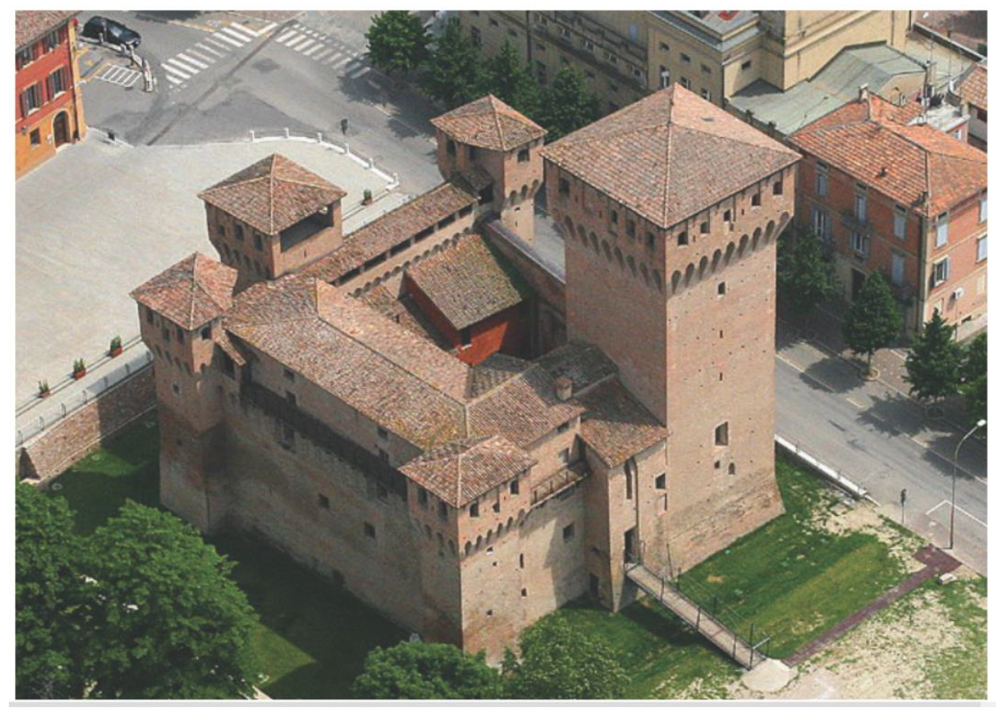
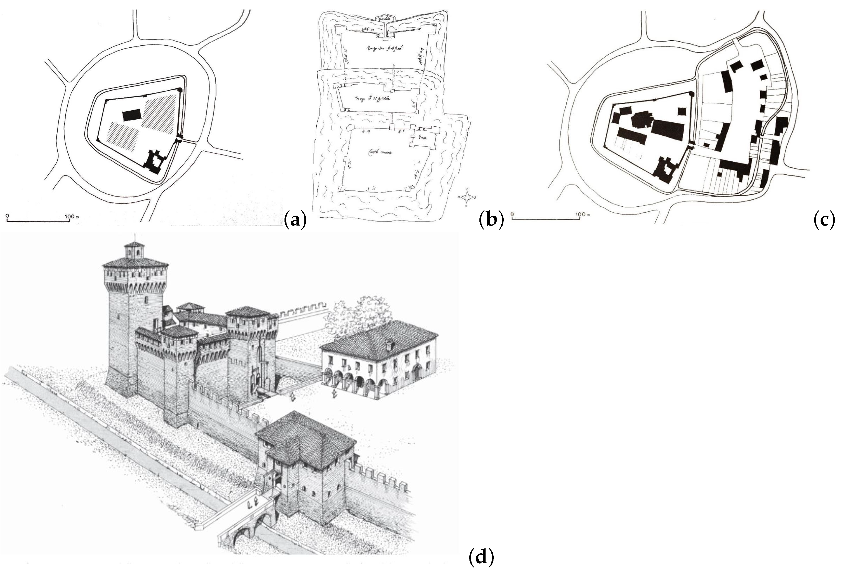
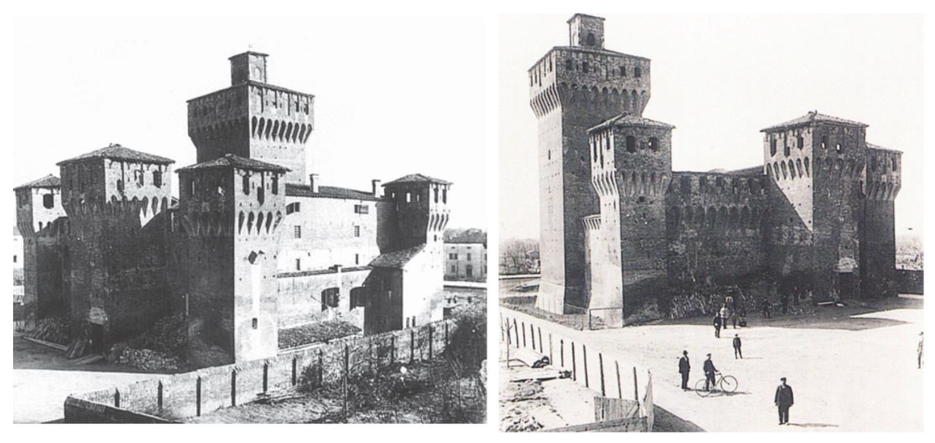
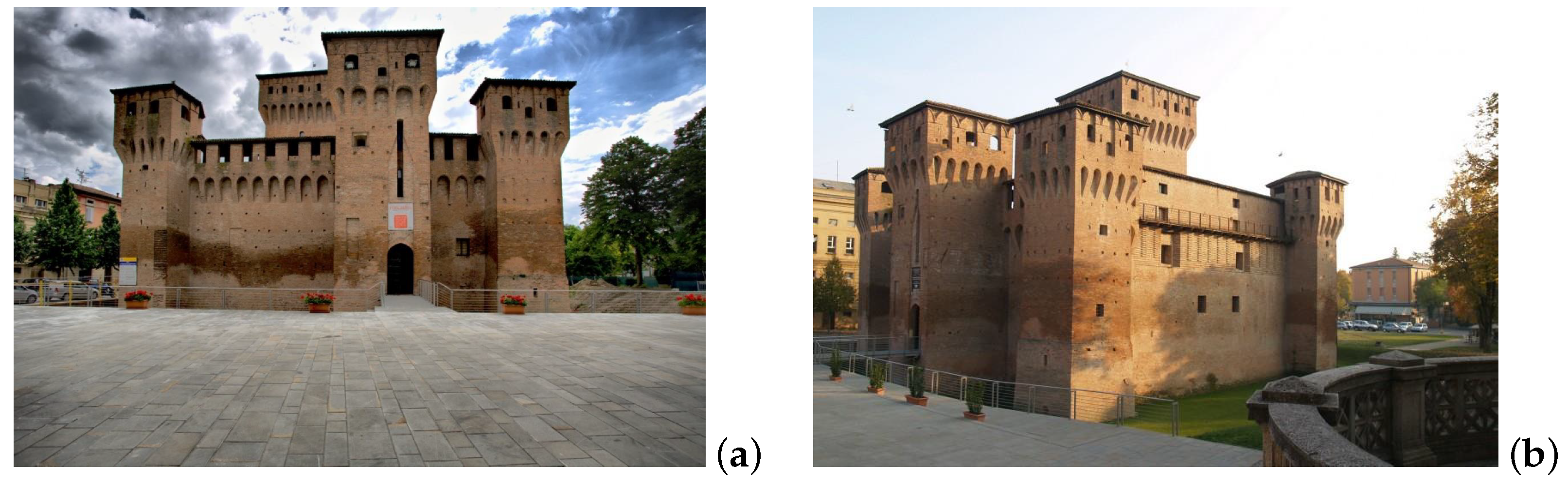
2. Case Study Description
3. Modeling Methodology
3.1. Objectives of the Mock-Up Model
3.2. The Modeling Process
3.2.1. Compilation of Available Documentation
3.2.2. Vectorization of Historical Plans
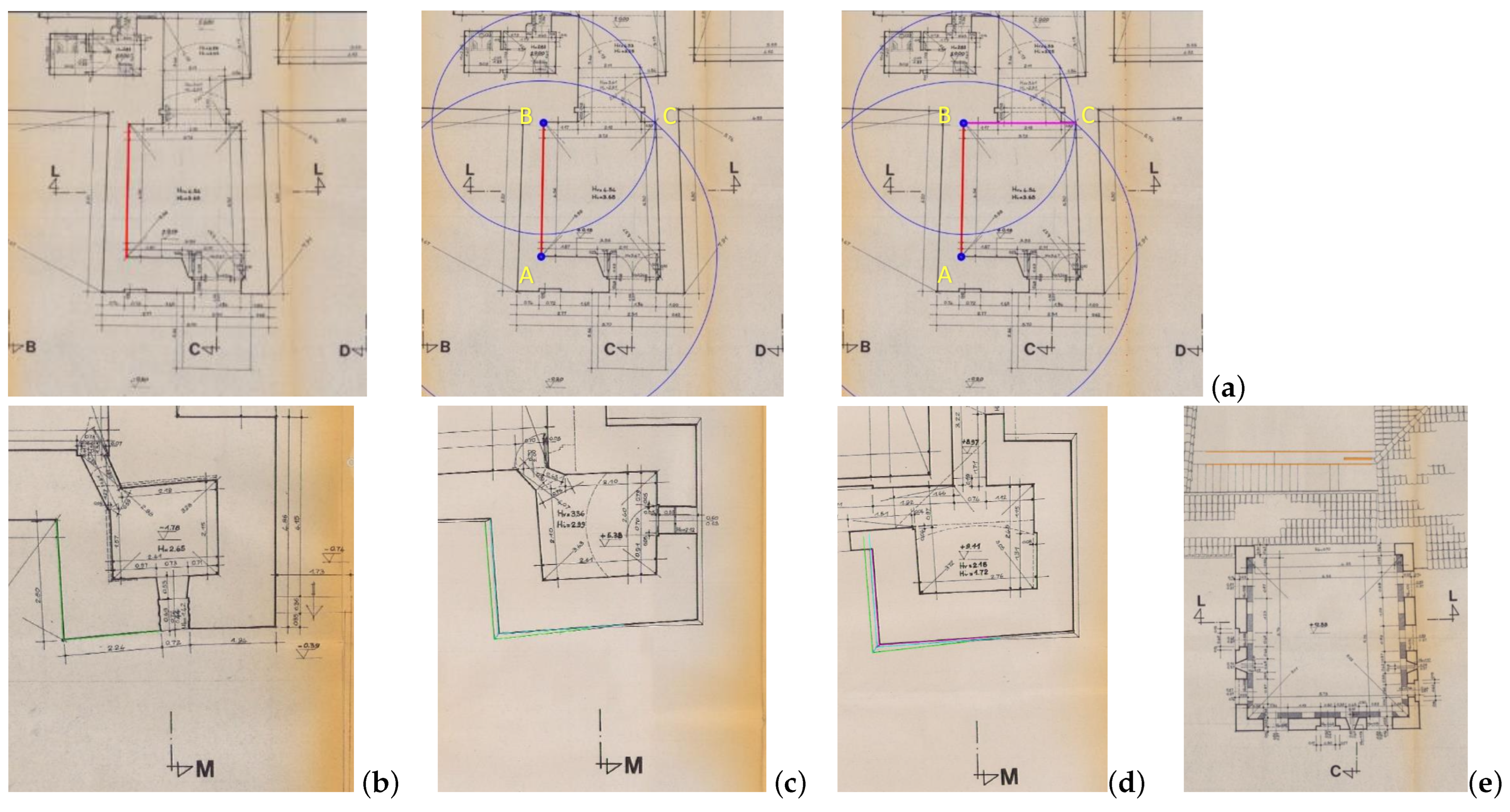
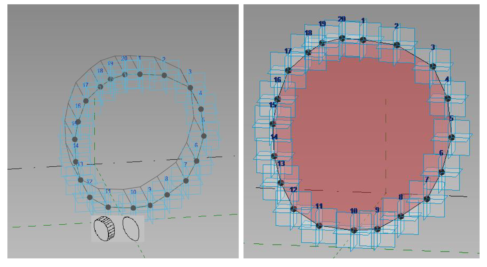
- Pre-1985 Plans: The 1985 survey was conducted to obtain geometric data on the fortress, serving as a reference for the entire restoration project. It consisted of twenty-one sheets, including seven plan views that roughly represented each floor of the fortress, along with elevations and cross-sections.The files representing the north tower were selected and imported into AutoCAD 2020, which is released by Autodesk, the same software house as Revit. The goal was to create a single DWG file containing vectorized representations of the walls and openings as seen in the PDFs, accurately positioned in 3D space. This DWG file would then be imported into the Revit environment as an external reference, serving as a trace for modeling the elements.However, this process encountered some challenges, primarily due to missing annotations. A minor issue was the absence of “north” indications in all the drawings; it was only present in the small plan of the area within the title block. Moreover, the drawings were not oriented in alignment with the title block map, which introduced uncertainty regarding the correct orientation. Nevertheless, for this work, orientation was not a critical concern.Some concerns also arose when loading the PDFs into AutoCAD. Despite being imported with their scale, it did not match the intended scale. This discrepancy could have resulted from approximations during the digitization phase or wrinkles in the paper.To enhance accuracy, the PDFs needed to be resized within CAD. This was accomplished by using a known measurement as a reference for each floor [24]. A carefully chosen line, situated away from paper folds to avoid deformations, was used as the reference. For consistency, the internal profile of the eastern wall of the tower was chosen as the reference for scaling the rest of the building, as it was located in a flatter and less folded area of the blueprints, see Figure 7.The final missing element was a closed triangulation network. After scaling the plans, the next step was to vectorize them, making them loadable into Revit and allowing interaction for wall placement. A robust triangulation network would have made it easier to reconstruct the geometry of walls and openings, as it provides reliable measurement information through a network of interconnected dimensions.Despite the absence of a formal triangulation network, lines could be sketched using a simple typical topographical approach based on the triangulation of points using circles, see Figure 7 [25]. Starting from a line, to determine the orientation of an adjacent one, two circles were centered over the two ends of the first line. The radius of these circles equaled the distance of these two points from the other end of the second segment. This geometric construction allowed the circles to intersect at the final point of the line that needed to be created.This method works only with redundant measurements when at least two measurements are converging for each point. In general, the obtained discrepancies were on average about 2 cm or below, which could be assumed as a quite good error when dealing with masonry structures. To sum up, the origin of these differences can be the result of:
- Absence of a scale bar and a closed polygonal and the redundance of measures.
- Accuracy, precision, and error of the tools used to take the lengths; since no benchmark points are reported in the documents, it could be assumed that were used mainly analogic instruments.
- Errors due to rounding of the measurings.
- Accuracy of the drawings.
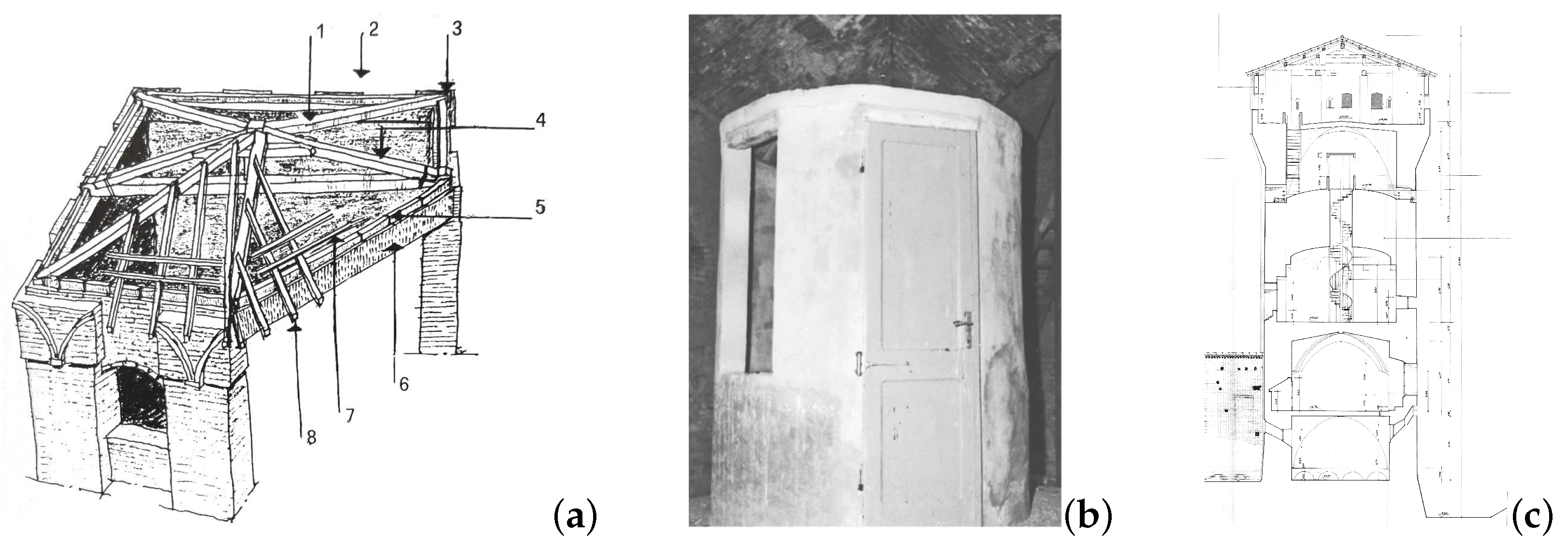
Eventually, once each of the four plans had been completely vectorized, they were stacked according to their reference plane. Since the actual value was not reported on the plan, the section height was assumed 1 m over the flooring, but this will be added directly on Revit when modeling the walls.The benchmark to stack one element over the other was a portion of the footing of the north-west tower, since it was the only common element among all the plans. Instead, on the fourth floor, since the corner was hidden by the roof, it was used as a reference to the brick parapet of the courtyard staircase (which was also present in the second-floor plan). Indeed, in this case, it would have been better to have a network of external benchmarks to correctly orientate all the plans according to the very same reference system. - 1990s Plans: The works carried out during the 1990s did not alter the external geometry of the north tower. However, this set of drawings reveals other completed or proposed interventions. From a visual perspective, these blueprints closely resemble the previous ones, except for the absence of measurements, which were later added with a pencil and roughly approximated from the originals.The primary differences between the two sets of drafts were the installation of window frames and the construction of a new spiral staircase to connect the second floor and the battlements.The staircase, constructed of wood and steel, was intended to replace a movable wooden ladder that had been used externally on the tower in a corner nearer to the door to avoid interfering with the use of the room.As these documents do not provide significant additional information about the structure of the tower, there was no need to vectorize these PDFs either, as they were essentially interchangeable.
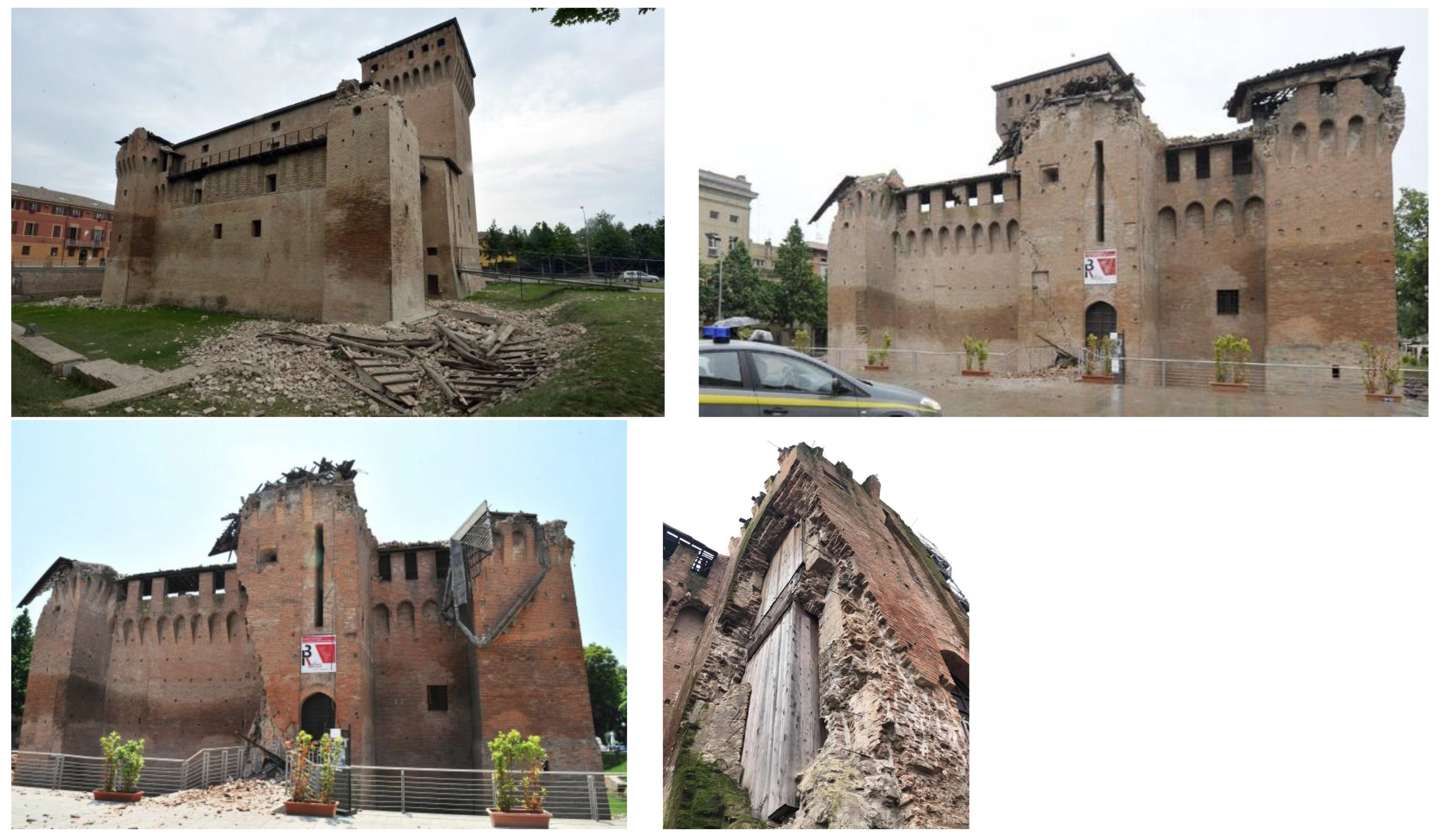
- Post-Seismic Plans: The set consisted of ten DWG files, each corresponding to one of the fortress’s levels. Unlike the other blueprints, these plans were highly accurate as they were generated from a TLS (Terrestrial Laser Scanning) survey. They were also very self-explanatory, featuring numerous useful references, such as the north arrow and actual height indications on the cross-sections. Each view was designed to facilitate easy stacking of frames around the plan, showcasing the same area at different heights. The final output resulted in a DWG file similar to the previous one that was created.Since the two DWG files were not based on the same reference system, they lacked consistency between them due to the absence of benchmarks connecting both. However, as a final step in the modeling process, a conceptual mass was reproduced using the last DWG as a reference. To place this mass within the same environment as the first one, the north wall of the fortress, connecting the three towers, was assumed as a reference point. This assumption could be supported by the fact that the earthquake propagated along the east–west axis of the fortress, and the wall withstood in-plane stress, indicating that it should not have moved along its axis, making it reliable for qualitative analysis.
4. Logical Organization of the BIM Database
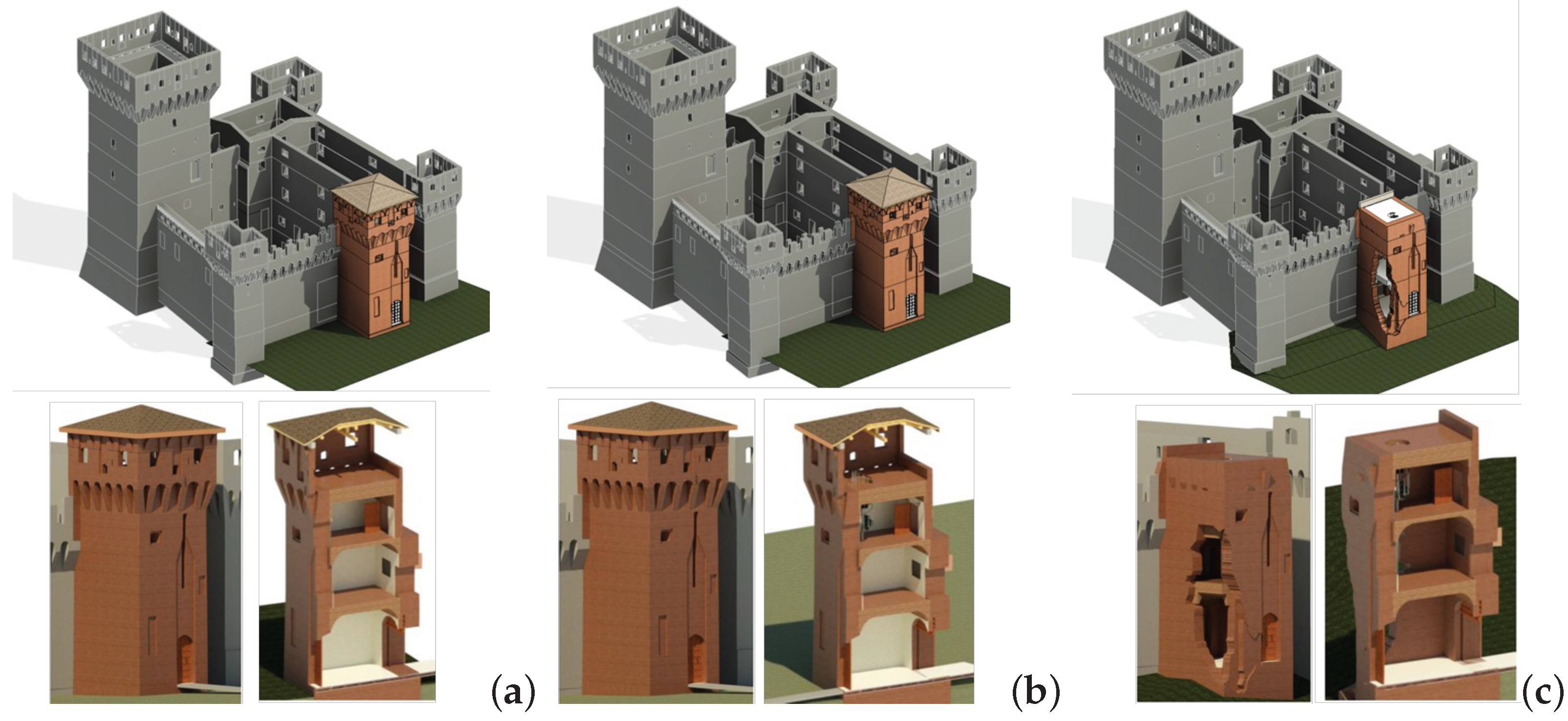
4.1. Late Historical Phases and Considered Configurations
- 1985: This initial phase is based on the DWG files derived from the survey conducted by architect Savioli in 1985. It serves as the foundational reference for subsequent modeling efforts.
- Support 1: As the name suggests, this phase is not intended to represent a specific historical timeframe, but is designed solely to demolish walls that needed to be recreated in the model for the 1990s phase.
- 1990s: This phase closely mirrors the geometry of the previous 1985 phase. However, it incorporates key updates, such as the addition of the new spiral staircase and windowpanes, reflecting the architectural changes over the decade.
- 2012: In this phase, we focus on representing the collapsed portions of the structure, documenting the impact of the seismic event.
- 2012-LS: The final phase derives from the DWG files produced by Comes Studio Associato. It serves to highlight the differences and potential limitations between the two modeling approaches, offering valuable insights into the structure’s evolution.
- Alongside the definition of these phases, corresponding visualization filters were established, see Figure 8.
4.1.1. Pre-Remodeling
4.1.2. After Remodeling—Before Seismic Event
4.1.3. After the Seismic Event
4.2. Elements Modeled in Detail
4.2.1. Walls
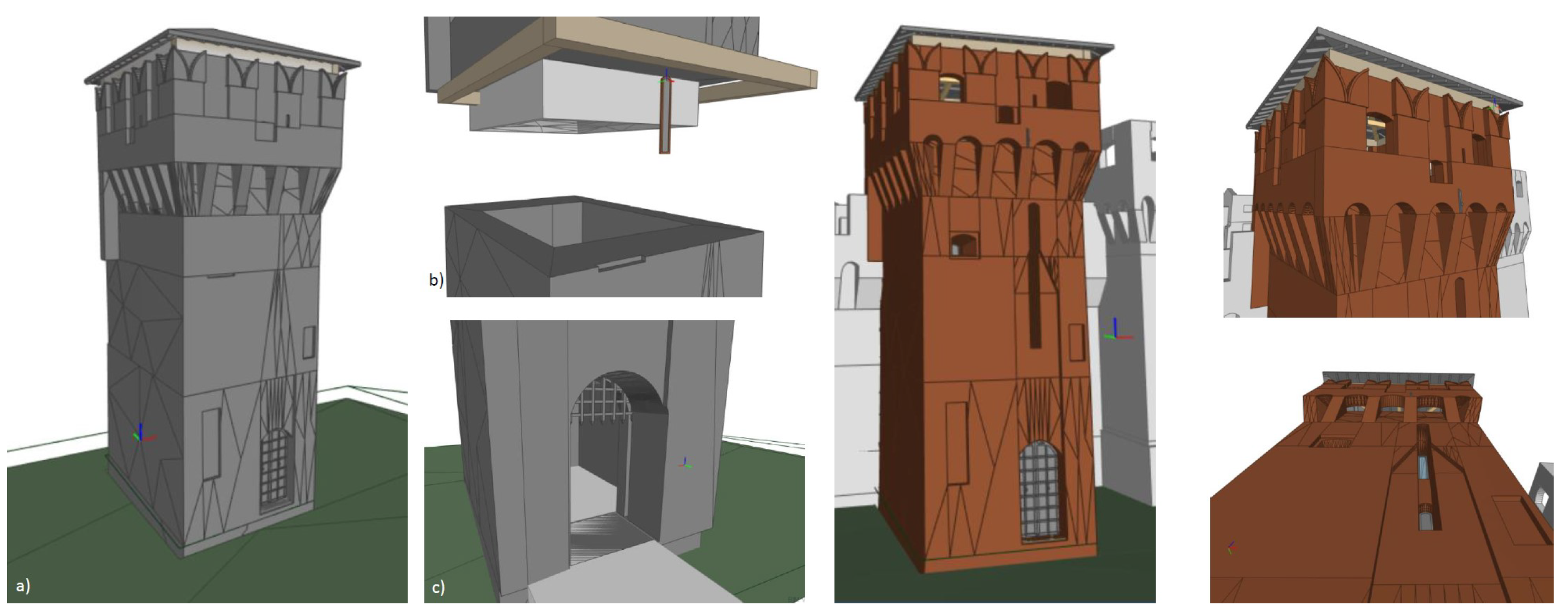
4.2.2. Vaults
- Keel Vault: Located on the ground floor.
- Cloister Vault: Situated on the first floor.
- Barrel Vault: Positioned on the ground floor.
- (a)
- Open a Metric Generic Model Adaptive family template.
- (b)
- Add four Point elements in a clockwise arrangement under the Reference category. Select all four points and designate them as adaptive.
- (c)
- Create splines through pairs of adjacent points. Select all the splines and mark them as Reference Lines.
- (d)
- Shape the adaptive family using the Draw Section tools. Certain dimensions needed to be parameterized based on vault type:
- For the Keel vault, parameters included length, height, radius, and height of the flat portion (known as “schifo” in Italian).
- For the Barrel vault, parameters pertained to both the initial and ending radii.
- (e)
- Convert the measures created in the previous step into parameters. Ensure proper labeling and determine whether each parameter should be a Type or Instance property based on context. Parameters dependent on other variables should be grouped under “Constraints” in the dropdown menu.
- (f)
- Create the Void Form necessary for carving away sections from the flooring system. The procedure varies slightly for the two vault types:
- For the Keel vault, select the shape form first, followed by the reference line, and then press the “Void Form” button.
- For the Barrel vault, select both the starting and ending profiles before pressing “Void Form”.
- (g)
- Save the family and load it into the project. Once correctly positioned, use the “Cut Geometry” function to subtract it from the flooring, achieving the desired vaulted shape.
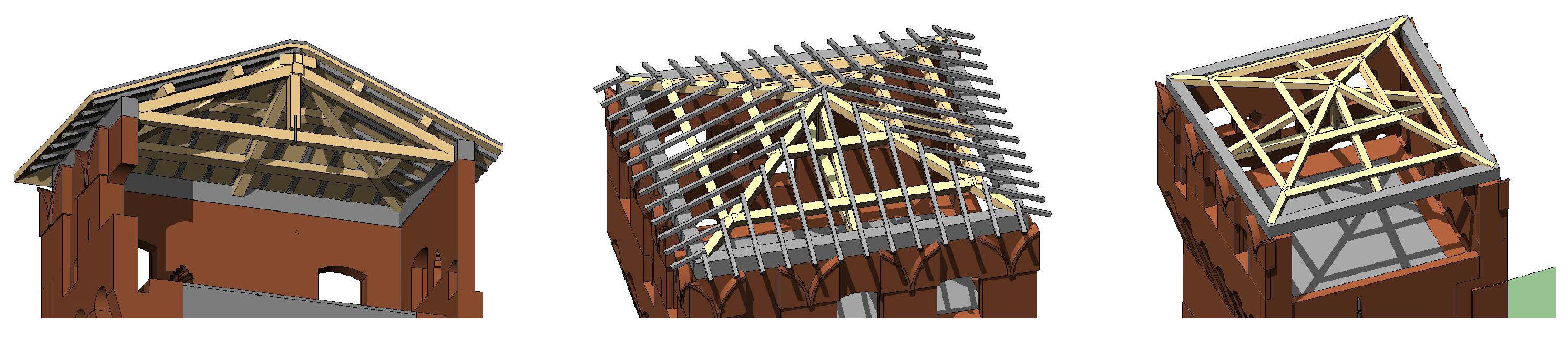
4.2.3. Roofing System
4.2.4. Openings
- Doors
- There are four doors in the tower: two on the ground floor and one each on the first and second floors. The first two doors are unique, as this tower used to serve as the gate between the fortress and the town, and they possess distinctive features.The external entrance door features two carved wood panels with studs and two metallic door knockers. To model this door, a Metric Model template was used, and the masonry was shaped by combining various types of voids to achieve the actual form. Afterward, all the other elements of the door were added.The other passage serves as a short gateway with a barrel vault and an old wooden portcullis designed to prevent enemies from entering. Modeling the hole in the masonry required using the Blend tool, as the two sides of the wall have different widths. The lattice wooden structure of the portcullis has also been represented, although it is unclear where it ends, as the cross-section suggests that it may be too short to span the full height.The last two doors, which grant access to the first and second floor, have a different doorway, but their wooden structure is quite similar. Unfortunately, there was not enough data to design in detail the two panels, since they are only visible in the panoramic reconstruction, while they are simply sketched in the blueprints.
- Windows
- Differently from the doors, windows could be grouped according to some sort of archetype, except for the two long and narrow openings facing north, which used to house the lifting harm of the drawbridge, and the other two facing the courtyard, which are protected by iron bars. The two narrow windows, even though they are quite similar (one is just longer than the other) were modeled separately because of the masonry molding. In addition, the ones with iron bars had to be modeled separately, since the metal lattice was not parametrizable and was composed of cylindrical elements. Furthermore, the window facing north on the second floor was modeled separately because of its molding. At first glance, all the windows at the battlement level seem to have the same proportion, but they slightly differ in the rising ratio. In any case, they could be grouped into two main types: large and small ones. Both types were modeled using a Metric Window family, and using a simple hole in the wall since they are just this in reality. In both cases, the height and width are instance parameters, so that each opening could have its measure according to the survey; instead, the radius of the top arch must be set as a constraint function, since it depends on the value of the rise and width of the window.
- Merlons
- The merlons had been modeled parametrically since they were all based on the same design; they only had different dimensions. They were designed as a simple swallowtail merlon (or Ghibelline, in Italian) using a Metric Generic Model wall-based template, to allow the creation of elements hosted by a wall: the merlons are connected to a wall that is probably deriving from the rose of the battlement (a parapet with a defensive purpose). In this way, the relationship between the wall and the battlement is preserved. All the main dimensions and the V-shaped notches of the top were parametrized to adapt to any width modification. Later, this object served as a base to shape the other battlements that were unique. In particular, the corner ones needed to be modeled aside, since they had to adhere to walls that have different orientations, but also because their notches were merging along the bisector. The last one to be modeled was the type with the embrasure on the front side. In this case, too, the base was the standard merlon, to which was added a narrow opening that was made parametric, since it was needed by three elements, but all in different positions, heights, and widths.
4.2.5. Stairs
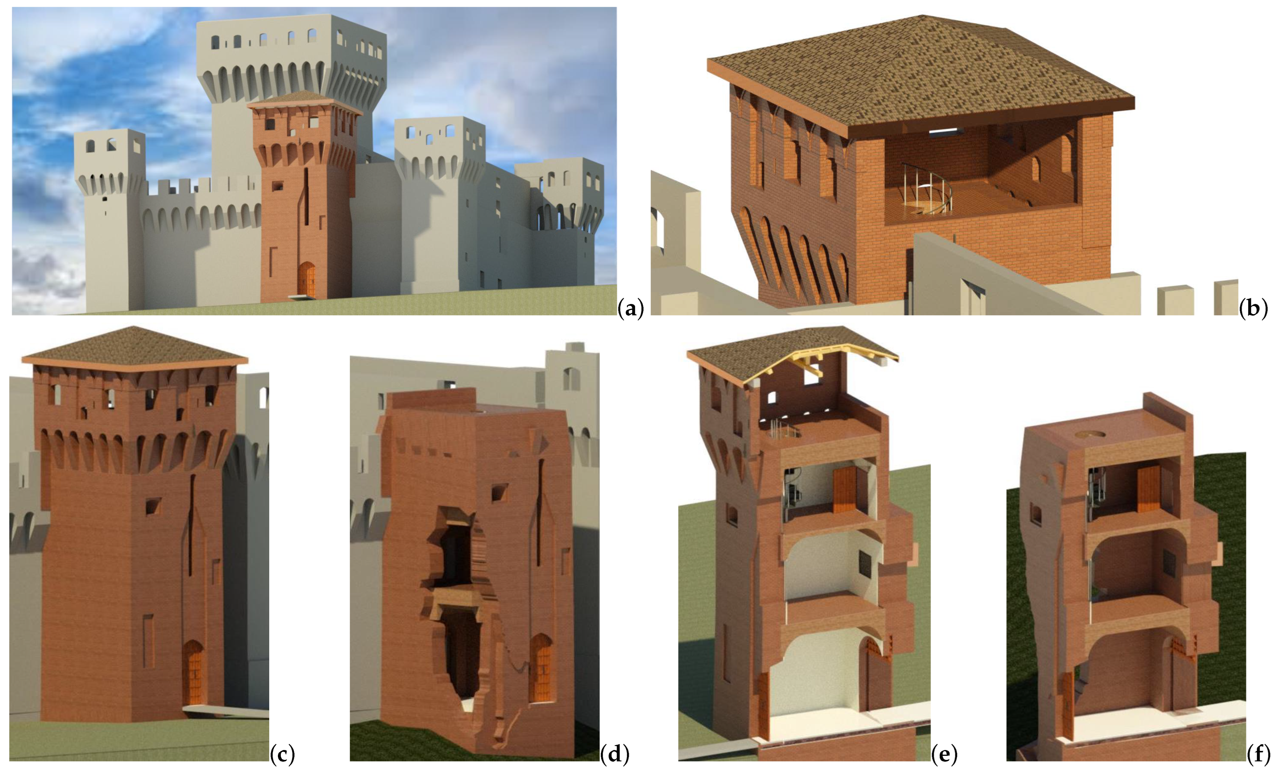
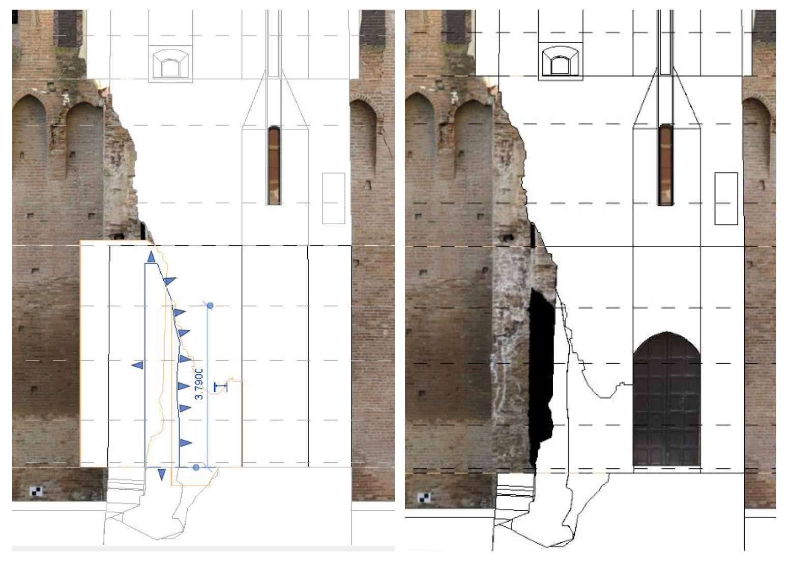
4.3. Representing Collapsed Portions
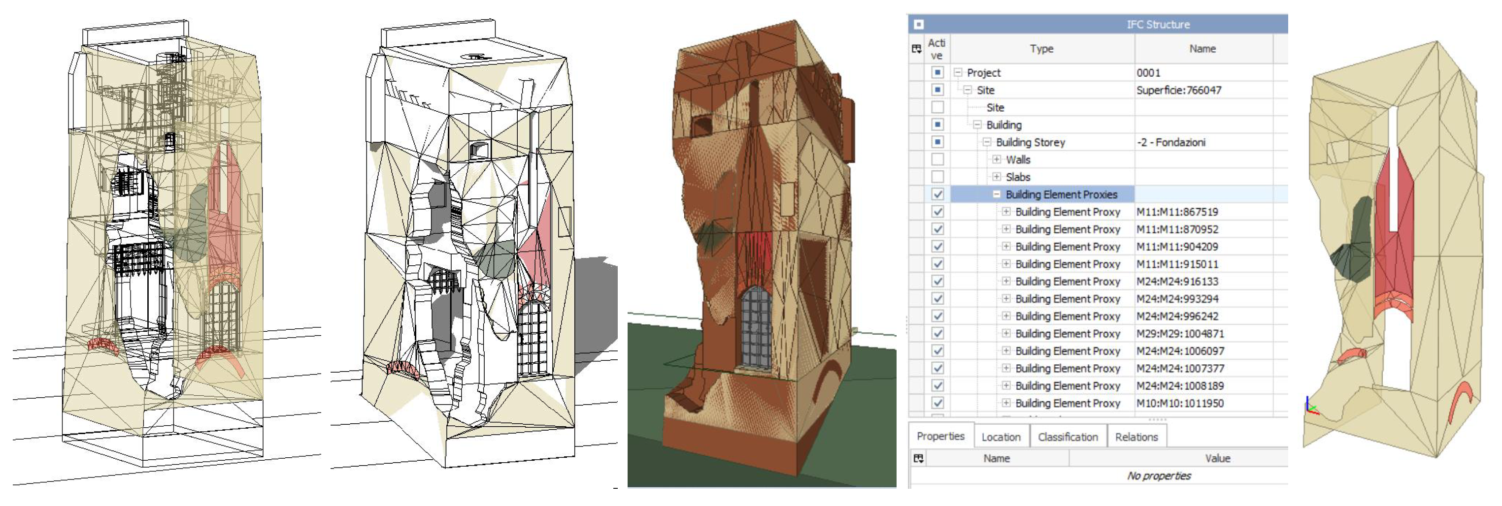
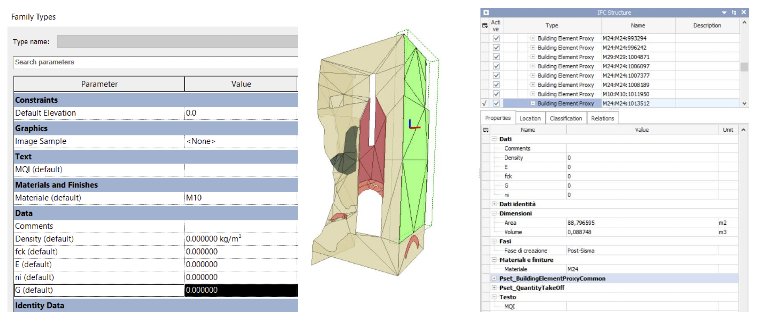
5. Semantic Enrichment Using Patch-like Objects
6. Inception—A Versatile Online BIM Database for Historical Cultural Heritage Management
6.1. Features and Integration
6.2. Interactive Exploration and Semantic Querying
6.3. Management of Historical-Cultural Heritage
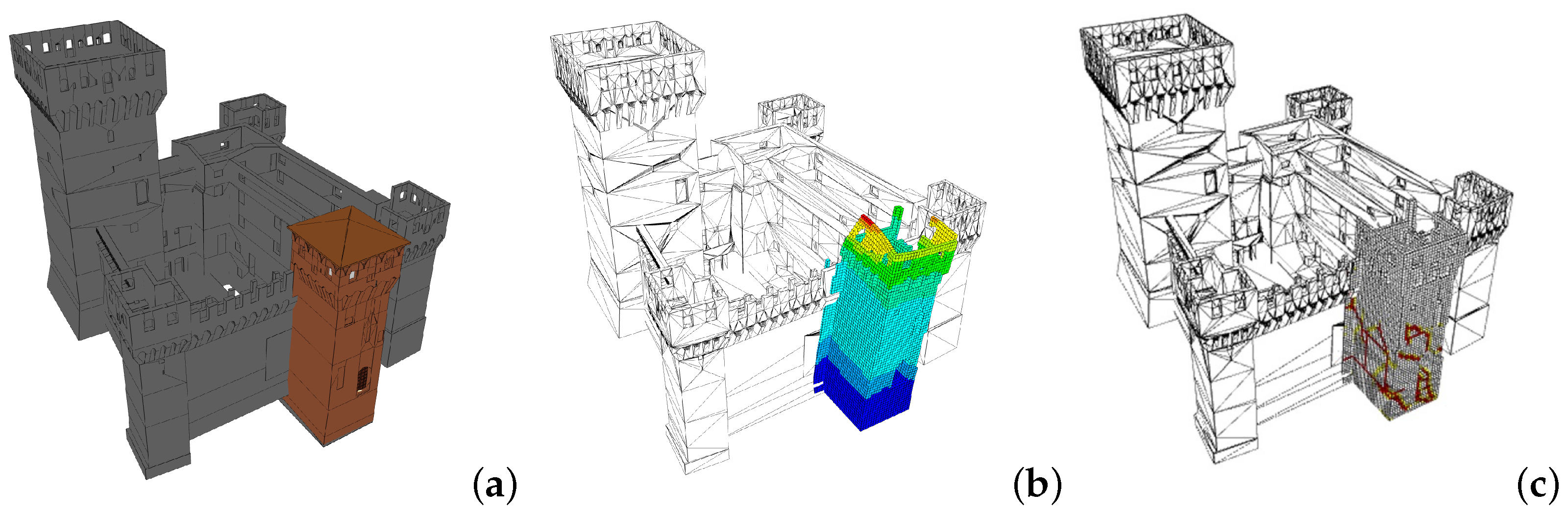
- (a)
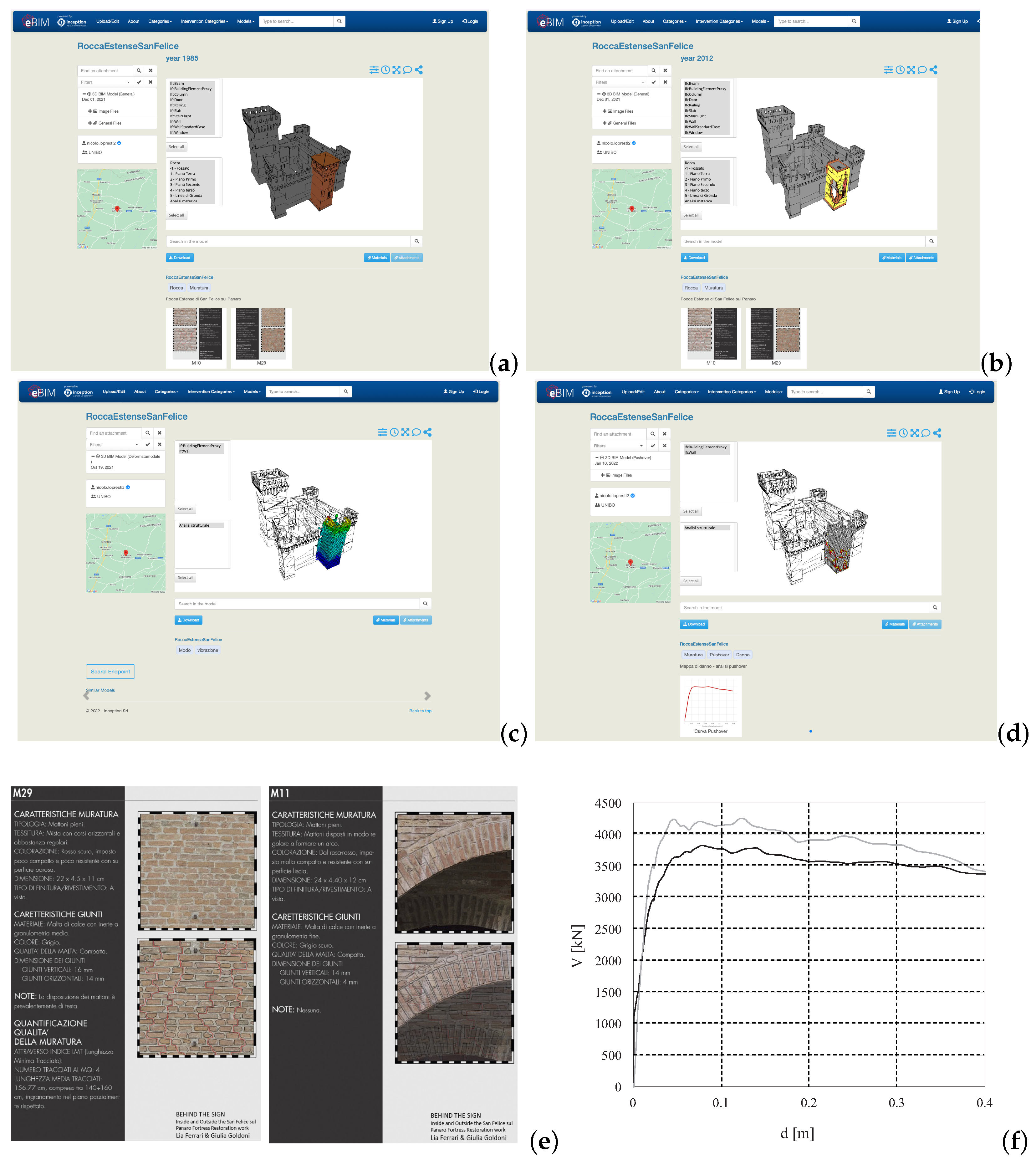
- Three-Phase Model: This model resides within a single IFC file. Although it may initially appear cluttered when viewed using an IFC viewer such as BIMVision, where elements from the three phases are superimposed, Inception automatically segregates these phases. To achieve this, every element in the IFC file must be tagged with the phase to which it belongs. This practical task is accomplished by defining a property set called “INCEPTION-phasing” for each component, which serves as a container to store consistent properties, including phase specifications (e.g., phase = 1990 or phase = 2012). Inception recognizes this property set and effectively segregates the three models. The IFC file was directly exported from Revit.
- (b)
- North Tower Modal Shape Model: This model represents the modal shape of the north tower. It essentially serves as a synthetic representation of results obtained through finite element analyses conducted on the north tower’s structural behavior [32]. Here, colors represent the Modal Shape amplitudes.
- (c)
- Pushover Model: Similar to the modal shape model, this model also results from finite element analyses performed on the north tower. These analyses generated a substantial amount of data that is not easily represented within a BIM environment such as Inception. Thus, we aimed to create a synthetic representation of the structural analysis outcomes, which can be readily understood by all stakeholders [24].
7. Conclusions
Author Contributions
Funding
Data Availability Statement
Acknowledgments
Conflicts of Interest
References
- Lee, S.; Park, H.W. Development of a web-based historic building information modeling platform. J. Comput. Civ. Eng. 2020, 34, 04020032. [Google Scholar]
- Araldi, A.; Bartolini, C. An Ontology-Based Approach to Enrich HBIM Data Models for Cultural Heritage Documentation. Appl. Sci. 2021, 11, 145. [Google Scholar]
- Alattas, Y. Integrating Geospatial Information into Heritage Building Information Modeling (HBIM) for Enhancing Management and Decision Support. ISPRS Int. J. Geo-Inf. 2021, 10, 108. [Google Scholar]
- Maggiore, F.; Flórez, L.S. Digital innovation in heritage conservation: 3D modeling of the Nasrid’s House of the Desert at the Alhambra. In Proceedings of the IEEE Digital Heritage International Congress (DigitalHeritage), Marseille, France, 28 October–1 November 2013; pp. 277–280. [Google Scholar]
- Achille, C.; Alby, E. HBIM for preventive conservation and valorization of existing built heritage. ISPRS Int. J. Geo-Inf. 2015, 4, 1723–1741. [Google Scholar]
- Arnold, D.; Costello, B. Integrating building information modeling (BIM) and geographic information systems (GIS) for historic building documentation. J. Cult. Herit. 2010, 11, 424–433. [Google Scholar]
- Rinaudo, F.; Dalmasso, D.; Osello, A. HBIM: A review. J. Cult. Herit. 2017, 28, 65–73. [Google Scholar]
- Yi, Y.; Liu, Z.; Zhang, X.; Ma, X.; Zhang, H. Towards a semantic building information modeling for existing buildings. Autom. Constr. 2018, 94, 270–280. [Google Scholar]
- Frison, C. Il «Castellum Sancti Felicis» tra X e XIII secolo: Paesaggio, società, istituzioni. In La Rocca Estense di San Felice sul Panaro. Studi e Ricerche su un Fortilizio dell’Area Padana dal Medioevo all’Età Moderna, 1993, San Felice sul Panaro; Calzolari, M., Campagnoli, P., Frison, C., Eds.; Gruppo studi Bassa Modenese: San Felice sul Panaro, Italy, 1994; pp. 169–196. [Google Scholar]
- Ferrari, L.; Goldoni, G. DIETRO IL SEGNO Dentro e Fuori il Restauro della Rocca di San Felice sul Panaro. Master’s Thesis, University of Parma, Parma, Italy, 2014. [Google Scholar]
- Andreolli, B. Il castello e la rocca di San Felice nel Basso Medioevo. In La Rocca Estense di San Felice sul Panaro. Studi e Ricerche su un Fortilizio dell’Area Padana dal Medioevo all’Età Moderna, 1993, San Felice sul Panaro; Gruppo studi Bassa Modenese: San Felice sul Panaro, Italy, 1994; pp. 197–210. [Google Scholar]
- Gelichi, S.; Campagnoli, P.; Librenti, M.; Chimenti, M. Gli scavi archeologici nella Rocca estense di San Felice sul Panaro. In La Rocca Estense di San Felice sul Panaro. Studi e Ricerche su un Fortilizio dell’Area Padana dal Medioevo all’Età Moderna; Calzolari, M., Campagnoli, P., Frison, C., Eds.; Gruppo studi Bassa Modenese: San Felice sul Panaro, Italy, 1994; pp. 61–118. [Google Scholar]
- Gavioli, F. La Rocca di San Felice: Alcuni ricordi. In La Rocca Estense di San Felice sul Panaro. Studi e Ricerche su un Fortilizio dell’Area Padana dal Medioevo all’Età Moderna, 1993, San Felice sul Panaro; Calzolari, M., Campagnoli, P., Frison, C., Eds.; Gruppo studi Bassa Modenese: San Felice sul Panaro, Italy, 1994; pp. 19–24. [Google Scholar]
- Perogalli, C. La Rocca di San Felice: Un fortilizio fra Tre e Quattrocento. In La Rocca Estense di San Felice sul Panaro. Studi e Ricerche su un Fortilizio dell’Area Padana dal Medioevo all’Età Moderna, 1993, San Felice sul Panaro; Calzolari, M., Campagnoli, P., Frison, C., Eds.; Gruppo studi Bassa Modenese: San Felice sul Panaro, Italy, 1994; pp. 25–34. [Google Scholar]
- Calanca, A. Terra e castello di San Felice sul Panaro nella cartografia storica dal XVI al XIX secolo. In La Rocca Estense di San Felice sul Panaro. Studi e Ricerche su un Fortilizio dell’Area Padana dal Medioevo all’Età Moderna. Atti della Giornata di Studi (29 Maggio 1993); Calzolari, M., Campagnoli, P., Frison, C., Eds.; Gruppo studi Bassa Modenese: San Felice sul Panaro, Italy, 1994; p. 225. [Google Scholar]
- Cattini, M. Da struttura difensiva a nucleo urbano. Il castello nei primi due secoli dell’Età moderna. In La Rocca Estense di San Felice sul Panaro. Studi e Ricerche su un Fortilizio dell’Area Padana dal Medioevo all’Età Moderna, 1993, San Felice sul Panaro; Calzolari, M., Campagnoli, P., Frison, C., Eds.; Gruppo studi Bassa Modenese: San Felice sul Panaro, Italy, 1994; pp. 211–224. [Google Scholar]
- Piconi, S. Il restauro della Rocca di San Felice sul Panaro. In La Rocca Estense di San Felice sul Panaro. Studi e Ricerche su un Fortilizio dell’Area Padana dal Medioevo all’Età Moderna. Atti della Giornata di Studi (29 Maggio 1993); Calzolari, M., Campagnoli, P., Frison, C., Eds.; Gruppo studi Bassa Modenese: San Felice sul Panaro, Italy, 1994; p. 35. [Google Scholar]
- Dolce, M.; Nicoletti, N.; Ammirati, A.; Bianconi, R.; Filippi, L.; Gorini, A.; Marcucci, S.; Palma, F.; Zambonelli, E.; Lavecchia, G.; et al. The Ferrara Arc Thrust Earthquakes of May–June 2012 (Northern Italy): Strong-motion and Geological Observations—Report I. Available online: https://rischi.protezionecivile.gov.it/en/seismic/activities/emergency-planning-and-damage-scenarios/ran-national-accelerometric-network/ (accessed on 2 March 2021).
- Dolce, M.; Nicoletti, N.; Ammirati, A.; Bianconi, R.; Filippi, L.; Gorini, A.; Marcucci, S.; Palma, F.; Zambonelli, E.; Lavecchia, G.; et al. The Ferrara Arc Thrust Earthquakes of May–June 2012 (Northern Italy): Strong-Motion and Geological Observations—Report II. Available online: https://rischi.protezionecivile.gov.it/en/seismic/activities/emergency-planning-and-damage-scenarios/ran-national-accelerometric-network/ (accessed on 2 March 2021).
- Battilani, S. Arricchimento Semantico nel Contesto dell’Existing Building Information Modelling: Aspetti Metodologici e Applicazione al Caso della Rocca Estense di San Felice sul Panaro. Master’s Thesis, University of Bologna, Bologna, Italy, 2020. [Google Scholar]
- Mirza, C. Interoperabilità BIM nella Modellazione Strutturale di Edifici Storici in Muratura: Il Caso della Rocca Estense di San Felice sul Panaro. Master’s Thesis, University of Bologna, Bologna, Italy, 2021. [Google Scholar]
- UNI—Ente Italiano di Normazione. Edilizia e opere di Ingegneria Civile—Gestione Digitale dei Processi Informativi delle Costruzioni—Parte 1: Modelli, Elaborati e Oggetti Informativi per Prodotti e Processi; UNI: Milan, Italy, 2017. [Google Scholar]
- Pozzoli, S.; Bonazza, M.; Villa, S.W. Autodesk Revit Architecture 2020. Guida Completa per la Progettazione BIM; Tecniche Nuove: Milano, Italy, 2019. [Google Scholar]
- D’Altri, A.M.; Castellazzi, G.; de Miranda, S.; Tralli, A. Seismic-induced damage in historical masonry vaults: A case-study in the 2012 Emilia earthquake-stricken area. J. Build. Eng. 2017, 13, 224–243. [Google Scholar] [CrossRef]
- Docci, M.; Maestri, D. Manuale di Rilevamento Architettonico e Urbano; Ed. Laterza: Roma, Italy, 2009. [Google Scholar]
- Cusniriuc, V.T.; Flores, J.M. Bonvalle. Rilievo Metrico 3D, HBIM e VPL per la Salvaguardia del Patrimonio Architettonico. Master’s Thesis, Polytechnic University of Turin, Turin, Italy, 2019. [Google Scholar]
- Piaia, E.; Maietti, F.; Di Giulio, R.; Schippers Trifan, O.; Van Delft, A.; Bruinenberg, S.; Olivadese, R. BIM based Cultural Heritage Asset Management Tool. Innovative Solution to Orient the Preservation and Valorization of Historic Buildings. Int. J. Archit. Herit. 2020, 15, 897–920. [Google Scholar] [CrossRef]
- Iadanza, E.; Maietti, F.; Medici, M.; Ferrari, F.; Turillazzi, B.; Di Giulio, R. Bridging the gap between 3D navigation and semantic search. The INCEPTION platform. IOP Conf. Ser. Mater. Sci. Eng. 2020, 949, 012079. [Google Scholar] [CrossRef]
- Iadanza, E.; Maietti, F.; Ziri, A.E.; Di Giulio, R.; Medici, M.; Ferrari, F.; Bonsma, P.; Turillazzi, B. Semantic Web Technologies Meet BIM for Accessing and Understanding Cultural Heritage. Int. Arch. Photogramm. Remote Sens. Spat. Inf. Sci. 2019, XLII-2/W9, 381–388. [Google Scholar] [CrossRef]
- Bonsma, P.; Bonsma, I.; Ziri, A.; Iadanza, E.; Maietti, F.; Medici, M.; Ferrari, F.; Sebastian, R.; Bruinenberg, S.; Lerones, P. Handling huge and complex 3D geometries with Semantic Web technology. IOP Conf. Ser. Mater. Sci. Eng. 2018, 364, 012041. [Google Scholar] [CrossRef]
- Castellazzi, G.; D’Altri, A.M.; Bitelli, G.; Selvaggi, I.; Lambertini, A. From laser scanning to finite element analysis of complex buildings by using a semi-automatic procedure. Sensors 2015, 15, 18360–18380. [Google Scholar] [CrossRef]
- Castellazzi, G.; D’Altri, A.M.; de Miranda, S.; Ubertini, F. An innovative numerical modeling strategy for the structural analysis of historical monumental buildings. Eng. Struct. 2017, 132, 229–248. [Google Scholar] [CrossRef]
- Sassoni, E.; Mazzotti, C. The use of small diameter cores for assessing the compressive strength of clay brick masonries. J. Cult. Herit. 2013, 14. [Google Scholar] [CrossRef]
- Degli Abbati, S.; D’Altri, A.M.; Ottonelli, D.; Castellazzi, G.; Cattari, S.; de Miranda, S.; Lagomarsino, S. Seismic assessment of interacting structural units in complex historic masonry constructions by nonlinear static analyses. Comput. Struct. 2019, 213, 51–71. [Google Scholar] [CrossRef]


| Years | Phase | Description of Activities |
|---|---|---|
| 927–1195 | Medieval castrum | Initial construction of the fortress in response to the need for protection against raids and external threats during the fragmentation of the Carolingian Empire. |
| 12th–18th Century | Early fortress construction | Ongoing development, expansion, and adaptations to the fortress as its role and defensive needs evolved over time. |
| 1899–1910 | 1899 restoration | Major restoration work in 1899 aimed at preserving and restoring the fortress. Specific details of the restoration efforts during this year. |
| 1939–1945 | WW2 danger | Period of vulnerability and potential damage during World War II, with a possible impact on the fortress and its structures. |
| 1980s | 1980s restoration | Extensive restoration work was carried out in the 1980s to ensure the preservation and conservation of the historical fortress. Description of the restoration activities conducted during this period. |
| 2000s | 2000s archaeological campaigns | Archaeological investigations conducted in the early 2000s, revealing traces of settlements beneath the municipal house and the fortress, aligning with the definition of castra. |
| 2012 | Earthquake | Significant earthquake event with structural impact on the fortress, marking a new phase in its conservation and restoration efforts. |
Disclaimer/Publisher’s Note: The statements, opinions and data contained in all publications are solely those of the individual author(s) and contributor(s) and not of MDPI and/or the editor(s). MDPI and/or the editor(s) disclaim responsibility for any injury to people or property resulting from any ideas, methods, instructions or products referred to in the content. |
© 2023 by the authors. Licensee MDPI, Basel, Switzerland. This article is an open access article distributed under the terms and conditions of the Creative Commons Attribution (CC BY) license (https://creativecommons.org/licenses/by/4.0/).
Share and Cite
Castellazzi, G.; Cardillo, E.; Lo Presti, N.; D’Altri, A.M.; de Miranda, S.; Bertani, G.; Ferretti, F.; Mazzotti, C. Advancing Cultural Heritage Structures Conservation: Integrating BIM and Cloud-Based Solutions for Enhanced Management and Visualization. Heritage 2023, 6, 7316-7342. https://doi.org/10.3390/heritage6120384
Castellazzi G, Cardillo E, Lo Presti N, D’Altri AM, de Miranda S, Bertani G, Ferretti F, Mazzotti C. Advancing Cultural Heritage Structures Conservation: Integrating BIM and Cloud-Based Solutions for Enhanced Management and Visualization. Heritage. 2023; 6(12):7316-7342. https://doi.org/10.3390/heritage6120384
Chicago/Turabian StyleCastellazzi, Giovanni, Enrico Cardillo, Nicoló Lo Presti, Antonio Maria D’Altri, Stefano de Miranda, Gregorio Bertani, Francesca Ferretti, and Claudio Mazzotti. 2023. "Advancing Cultural Heritage Structures Conservation: Integrating BIM and Cloud-Based Solutions for Enhanced Management and Visualization" Heritage 6, no. 12: 7316-7342. https://doi.org/10.3390/heritage6120384