Article

Evaluation of the Suitability of Electrokinetic Treatment to Desalinate the Limestone of the Tomb of Cyrus, a UNESCO World Heritage Site in Iran

1
Department Civil Engineering, Technical University of Denmark, 2800 Kgs. Lyngby, Denmark
2
Defense University Center at Spanish Naval Academy, University of Vigo, 36920 Pontevedra, Spain
3
Geological and Geophysical Engineering Department, Faculty of Petroleum and Mining Engineering, Suez University, Suez 43721, Egypt
*
Author to whom correspondence should be addressed.
Heritage 2023, 6(11), 6993-7008; https://doi.org/10.3390/heritage6110365
Submission received: 13 September 2023 / Revised: 13 October 2023 / Accepted: 26 October 2023 / Published: 28 October 2023

Abstract

:
The tomb of Cyrus the Great, founder of the Persian Empire, is considered one of the most important monuments of Iran. Its advanced state of deterioration motivated the need to carry out a study focused on analyzing the possible damage caused by the presence of soluble salts, and to assess the suitability of an electrokinetic treatment for their extraction. Preliminary diagnostics carried out on stone samples taken from the tomb confirmed that it is affected by the action of soluble salts, and especially by the presence of nitrates and sulfates. The effectiveness and possible harmful effects caused by electrokinetic treatment were evaluated, under laboratory conditions, using the same limestone that makes up the tomb. The obtained results show that this treatment, in a short period of time, reduces the ionic content, reaching high percentages of anion extraction, without causing any damage, which indicates that it is suitable for this type of stone.

1. Introduction

The most significant geological material used in the built heritage throughout the ancient world, including Iran, is limestone. It has historically been used extensively in important monuments and world heritage sites, such as Takht Jamshid and Pasargadae. However, because of its high accessible porosity, limestone is vulnerable to damage caused by the entrance of external alteration agents, such as water and soluble salts.
Soluble salts are undoubtedly one of the main alteration agents in the degradation of porous building materials, such as ornamental stones and mortars. The deterioration caused by this alteration agent has been reported in several studies [1,2,3,4,5]. The damage caused by soluble salts is essentially physical and is favored by the periodic changes in state (solid–liquid) that the salts undergo due to changes in the relative humidity, temperature, and water content in the porous material [1]. This physical damage is evident when there are processes of the loss of material caused by the pressure generated by salts due to their crystallization, hydration, or thermal expansion within the pores of the stone material [1,3,6,7,8,9,10,11]. In addition, as a consequence of the alteration process caused by the salts, the affected material weakens, becomes more porous, and is more susceptible to the action of future subsequent altering agents (such as water, soluble salts, and biological colonization), which compromises its structural stability and long-term durability.
Salt weathering appears in the forms of scaling, detaching, and powdering, especially affecting the most superficial stone areas [3]. A wide range of important field observations and the mechanisms of decay in porous materials over several decays have been summarized by Arnold and Zehnder [4].
Desalination is a complex conservation strategy, and its implementation is pivotal when the historical surface is seriously under the threat of salt deterioration and material loss. All the desalination techniques are aimed at lowering the ion content in the porous building material as much as possible. The most common desalination methods, which have been used for many years for historical artefacts, are immersion baths and the application of different kinds of poultices [12,13,14] or even mortars [15,16]. Both techniques have certain limitations with respect to the extraction efficiency, as, in both techniques, the efficiency is constrained mainly by the permeability and pore size distribution of the porous material, and, in the case of poultices, it is also restrained by their pore size distribution [17,18,19]. Furthermore, in both cases, the desalination process is relatively slow when the treatment is applied directly on the damaged surface, which, in some cases, requires a previous pre-consolidation to minimize the possible loss of material by contact [20,21]. Additionally, the poultice depth extraction efficiency is poor, only going down to less than 4 cm [13,22]. Numerous studies on the usage of crystallization modifiers that postpone the nucleation of crystals inside the pores of the material have been conducted recently in an effort to improve the effectiveness of both treatments [16,23,24,25], allowing the crystallization of salts on the surface as efflorescence. However, the addition of these compounds may have harmful effects on the treated material, such as color change, which make them incompatible with certain materials [13]. Furthermore, there are no inhibitors to reduce the damage caused by salt mixtures [25,26].
The electrokinetic desalination of porous materials is a recent technique applied in the field of the conservation of stone materials that has shown great results, under laboratory conditions, in the treatment of bricks [27,28,29], granites [30,31], and sandstone [32,33,34,35]. Even in onsite applications on walls [36,37,38] and columns [39], this technique has demonstrated high efficiency in thick depths and good removal rates, particularly for chlorides and nitrates (efficiencies above 80%). The higher extraction rate obtained via this technique compared to the traditional methods is due to the fact that, with electrokinetic desalination, the ions present in the material are forced to migrate, as they are responsible for carrying the current between the electrodes. The depth of extraction will depend on the position of the electrodes and the magnitude of the circulating current.
There are few studies that have examined the suitability and effectiveness of the electrokinetic technique for the desalination of limestones [40,41]. Therefore, and considering the disadvantages associated with this technique, such as those mentioned below, it is necessary to dig deep into the existing knowledge in the field of the heritage conservation built with this stony material before considering applying this kind of treatment as a suitable desalination technique, especially in archeological sites as important as Pasargadae.
The main disadvantages to be considered are as follows:
(1)
Extreme pH changes around the electrodes, due to water hydrolysis (Equations (1) and (2)), which can cause new chemical alterations of the stone minerals. Especially worrisome is limestone, a material that is very sensitive to exposure to acidic pH, which can cause the dissolution of calcium carbonate.
At the anode
H2O → ½ O2(g) + 2H+ + 2e
At the cathode
2H2O + 2e → 2OH + H2(g)
The damage caused in limestones due to anode acidification when this technique is used has already been reported in a previous study [41];
(2)
The generation of micro-fractures, which can be caused by the mechanical stresses associated with the electric-field flow across the pores of the material [42]. This damage is higher in those materials containing piezoelectric minerals [43,44] and depends on the value of the current density applied.
The mausoleum of Cyrus the Great, which is primarily composed of limestone, exhibits an advanced alteration state with a progressive loss of material that could affect the historical value of the monument (Figure 1). There is powdering, pitting, and scaling of the substrates, among other weathering forms that can be clearly observed on different surfaces of the monument, mostly on the corners of its units [45]. Recent studies have indicated that the mechanical and chemical damage in this monument is mainly related to (1) biodeterioration processes caused by different lichens and fungi [46,47,48,49,50], and (2) the climatic conditions in which the monument is located, which favor frost damage, thermal stress, and continual wetting–drying cycles on the stone surfaces due to the exposure of its facades to high surface moisture and high insulation [45,48]. In spite of the numerous studies on the potential mechanisms of the tomb degradation, only a few studies have indicated that the damage may also be caused by the action of soluble salts [45,46,48], and none of them have established a possible intervention methodology to combat this alteration agent. For this reason, the present study was focused on the following: (1) carrying out a preliminary diagnosis in order to confirm whether or not the soluble salts are really damaging this monument, and (2) if there is actually a risk to the preservation of the monument in the future due to the presence of a sufficient amount of salts that could damage it, analyzing the suitability and effectiveness of the use of electrokinetic techniques to conduct a future desalination campaign.

2. Materials and Methods

2.1. Description of the Archaeological Site

The archaeological site of Pasargadae is located in the northwest of Fars province, 130 km from Shiraz, in the southern region of Iran, in an open area (Figure 2). This historical site, built by the order of Cyrus the Great, was the first capital of the Persian Empire and was included on the UNESCO World Heritage List in 2004. The site is surrounded by agricultural lands and is located near the Polvar River. The extreme daily variation in the climatic conditions to which this archeological site is subjected (in terms of temperature and relative humidity), as well as the conditions among seasons, favor the weathering of the monument. These conditions can be consulted in [48]: the highest value of the relative humidity occurs in winter (up to 80%) and the lowest occurs in summer (20%), reaching a daily variation up to 20%; the highest value of the temperature occurs in summer (up to 40 °C) and the lowest occurs in winter (−5 °C), reaching a daily variation up to 30 °C in some months of the year.
The tomb of Cyrus the Great is one of the most considerable and well-known Pasargadae monuments. This tomb was almost thoroughly constructed, as reported in other studies [49,50,51], with a beige limestone extracted from quarries located in the mountains northwest of the village of Sivand, located 50 km from Pasargadae. This limestone was also used in other important archeological sites in Iran, such as Takht Jamshid [51].
The visual inspection carried out in this study shows signs of the possible presence of salts in different parts of the monument (Figure 3), which cause both aesthetic damage (such as salt efflorescence) and the loss of material (via scaling and powdering). This damage is more pronounced on the southwest and southeast facades, probably due to the position of the monument facing the predominant wind direction and the greater incidence of sunlight on these faces of the monument. Both aspects have an influence on the evaporation rate, which favors an intense crystallization of salts both on the surface and in the layers close to it, depending on the solubility of the salts present. However, a detailed study is necessary to attribute this damage to the salts.

2.2. Previous Diagnosis and Sampling

To analyze whether soluble salts represent a real problem for the monument, four surface samples of the disaggregated stony material were taken. Also, because soil is one of the main sources of salts, especially in agricultural areas, such as those surrounding the monument, two samples were taken from the surrounding soil 50 m and 120 m from the tomb (in the direction of the wind that usually blows from the narrow valley of Baghegi towards the tomb) to analyze the origin of the salts. All the samples were crushed and homogenized. An amount of 10 g of each powdered sample was immersed in 100 mL of distilled water and stirred for 2 h. Each suspension was then filtered and, in the aqueous extraction, the anion content (Cl, SO42−, and NO3) was determined via ion chromatography (using a Dionex ICS-100 chromatograph, Thermo Scientific, Waltham, MA, USA).
In addition, and to study the suitability of the electrokinetic technique as a desalination technique for this type of stone, an ashlar of beige limestone was collected from the Pasargadae site, specifically from the area of Mozafari Caravansary, which is near the Tomb of Cyrus (Figure 2) and was built using stones that were taken from the remains of Pasargadae. From this ashlar, a block of 20 × 20 × 10 cm and 8 stone cubes of 5 × 5 × 5 cm were extracted.
The stone cubes were used to characterize the porosity and bulk density of the limestone following an international standard [52], the mineralogical composition via X-ray diffraction (MPD3000-GNR), and the chemical composition via X-ray fluorescence (PERFORMIX-ARL, Thermo Scientific, Waltham, MA, USA). The LOI (loss on ignition) was determined gravimetrically by recording the weight loss at 950 °C.
The limestone block was used to assess the electrokinetic treatment in the laboratory. For this purpose, the salt content in the block was increased via a contamination process similar to that described in [33]. The ion content of the saline solution used was (in g/L) NaCl (1.45), NaNO3 (8.63), and CaSO4 (2.05).
Before the contamination process, the limestone block was wrapped with plastic film, leaving only the two bases of 20 × 20 cm uncovered. One of the bases was put into contact with the saline solution for 2 days, favoring the absorption of the solution via capillary suction. This process, as shown in [33], hinders the evaporation of the saline solution from the lateral faces of the samples and favors the entrance of the saline solution into the samples, due to the solution trying to evaporate through the opposite base. After 2 days, the samples were taken out and left to dry at room temperature for another 2 days, completing a cycle of contamination. In the next cycle, the opposite surface was put into contact with the solution to distribute the salts as homogeneously as possible. A total of 15 contamination cycles were conducted. Finally, the block was left to dry for 4 days at room temperature, before the plastic film was removed.
At the end of the contamination process and before desalination, two prismatic samples of 10 × 10 × 5 cm (named S-1 and S-2) were extracted from the block. These samples were used to assess the effectiveness of the electrokinetic desalination treatment. The rest of the block was used to assess the initial anion contents (i.e., the anion contents of the samples before desalination). For this purpose, the block was drilled in its whole depth, in two different places, to provide powder samples in 3 ranges of depth (0–3.5 cm, 3.5–6.5 cm, and 6.5–10 cm). An amount of 10 g of each powder sample was immersed in 100 mL of distilled water and stirred for 2 h. After filtration, the anion content (Cl, SO42−, and NO3) was determined again via ion chromatography.

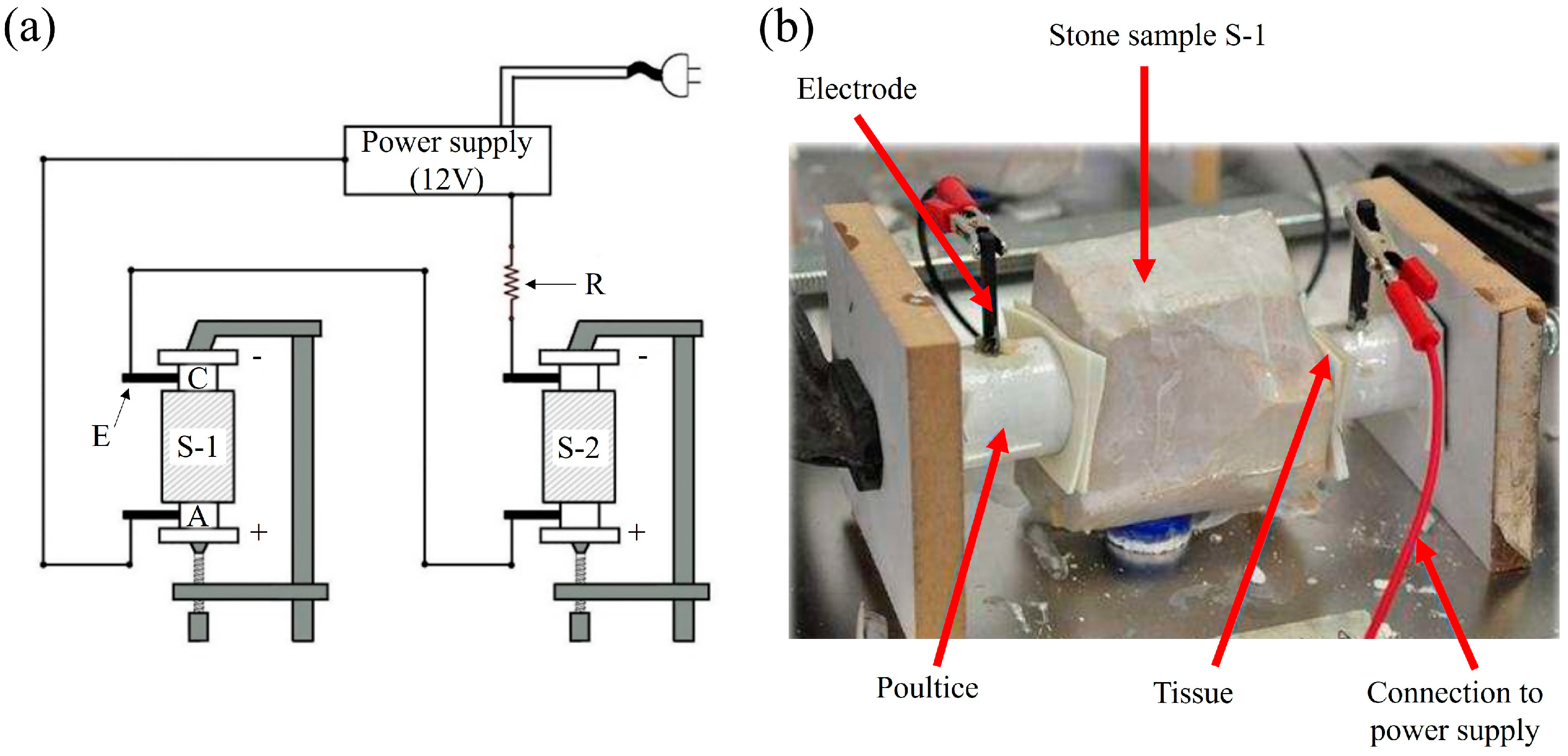
2.3. Electrokinetic Desalination Setup

Figure 4 shows a schematic view and picture of the desalination setup used in this study. This setup had two electrode compartments: the positive anodic compartment (A) and the negative cathodic compartment (C). A graphite electrode (E) of an 8 cm length and 4 mm diameter was housed in the poultices located in each of the electrode compartments. This material was selected as the electrode due to its inertness with respect to the oxidation reactions at the anode.
As a buffer electrolyte, a solution of 0.2 M sodium citrate–citric acid (pH 6) was used. The effectiveness of this electrolyte has been demonstrated in previous studies [31,33,39].
Two different poultices were used to retain the ions mobilized during the treatment, buffer the pH, and ensure good contact with the stone during the treatment. At the anode, a poultice made of a kaolin:CaCO3:buffer electrolyte in a ratio of 5:1:1.5 by weight was used. CaCO3 was added, according to [31,53], to strengthen the buffering capacity and hinder the acid pH, produced on the surface of the anode electrode, from reaching the surface of the stone (Equations (3) and (4)):
CaCO3 + H+ → Ca2+ + HCO3
HCO3 + OH → CO2(g) + H2O
At the cathode, a poultice made of a kaolin:buffer electrolyte in a ratio of 1.5:1 by weight was used. Kaolin, as demonstrated in [31,39], allows the retention of OH due to its ion exchange capacity. Consequently, the effectiveness of the electrokinetic treatment to remove the target ions is increased, as a decrease in the OH concentration results in an increase in the transfer number of the other anions, as demonstrated in [54].
To prevent the poultice from leaving any residues on the surface of the stone, a thin sheet of tissue was placed between both materials.
Regarding the electric circuit, both prismatic samples (S-1 and S-2) and a resistance of 1 kΩ (R) were connected in series, ensuring that the same current flowed through both samples. A constant voltage of 12 V was applied during the desalination treatment. This voltage was enough to reach a current density value close to 1 A·m−2 (sufficient current to mobilize the ions) from the beginning. The potential drop recorded at the resistance of 1 kΩ allowed for calculating the electric current that flows through each stone prism using Ohm’s law (Figure 4).
Before starting the desalination treatment, both prismatic samples (S-1 and S-2) were spray-wetted with distilled water. Afterwards, the samples were then completely wrapped with plastic film, leaving only two 3.8 cm diameter holes on each side of the sample to put the poultice and the surface of the stone directly in contact. This initial degree of humidity improved the flow of the electric current once the treatment was started. Furthermore, to hinder the drying of the prismatic samples during the treatment, the contact surface was re-wetted with ultrapure water at each poultice renewed, as in previous studies [33,38].
Once the electrokinetic desalination treatment starts, the electromigration occurs. During the electromigration process, as mentioned before, the positive ions (cations) are forced to migrate towards the cathode and the negative ions (anions) are forced to migrate towards the anode. In this way, the ions migrate towards the vicinity of the electrodes, outside of the stone, and are retained in the poultices.
During the treatment, every 8 h, the voltage drop between the electrodes of each sample and at the 1 kΩ resistance was measured using a multimeter. With these data, the evolution of the resistivity of the samples was recorded, using Equation (5), as well as that of the current density, using Equation (6).
ρ = R · S/l
where ρ is the resistivity in kΩ m; R is the resistance of each sample in kΩ; S is the cross section in m²; and l is the length of the sample in m.
J = I/S
where J is the current density in A m−2 and S is the cross section in m2.
The poultices were renewed every 24 h to measure the anion content removed. For this purpose, as stated in [33], each poultice was left to dry at 50 °C for 4 days, and it was then weighed, crushed by hand to a powder, and homogenized. Finally, 10 g of each powdered poultice was taken and immersed in 100 mL of distilled water. After filtration, the anion content was measured via ion chromatography in the aqueous extraction. pH measurements were also taken in the aqueous extraction, using a pH meter, and on the contact surface between the stone and the poultice, using pH strips.
The operation times of the desalination treatment applied in both prismatic samples were different, keeping the rest of the test parameters constant. Hence, at the end of the 6th day, the desalination of sample S-1 was considered ended (enough time to achieve high desalination percentages in other types of stones [31]). Sample S-1 was removed from the system and replaced by a fixed resistance of 10 kΩ. This resistance was selected, as it was the resistance value exerted by sample S-1 at the end of the 6th day. The desalination treatment was continued for another 4 days with sample S-2 (ending, in this case, after 10 days of desalination).
At the end of both assays, both stone prisms were uncovered and divided into three parts: the anode part (0–3.5 cm), middle part (3.5–6.5 cm), and cathode part (6.5–10 cm), to evaluate the effectiveness of the treatment at different depths. Powder samples were taken by drilling from each part, and aqueous extractions were prepared, following the procedure mentioned above, to analyze the anion content.
To quantify the effectiveness of the treatment, the percentage variation of the anion content in each of the zones in which the stone samples were divided, following Equation (7), and used in previous studies [13,31,33], was calculated:
Effectiveness % [ion]0-x cm = 100 ∙ [Initial ion content]0-x cm − [Final ion content]0-x cm/[Initial ion content]0-x cm
Negative percentages indicate that there was an increase in the anionic content in the analyzed area due to the mobilization of salts.
Finally, two samples from S-1 and another two from S-2 of 5 × 5 × 5 cm were taken to assess the effects of using electrokinetic techniques on the limestone properties (specifically the porosity and bulk density). Possible chemical changes in the mineralogy of the stones were analyzed via XRD.

3. Results and Discussion

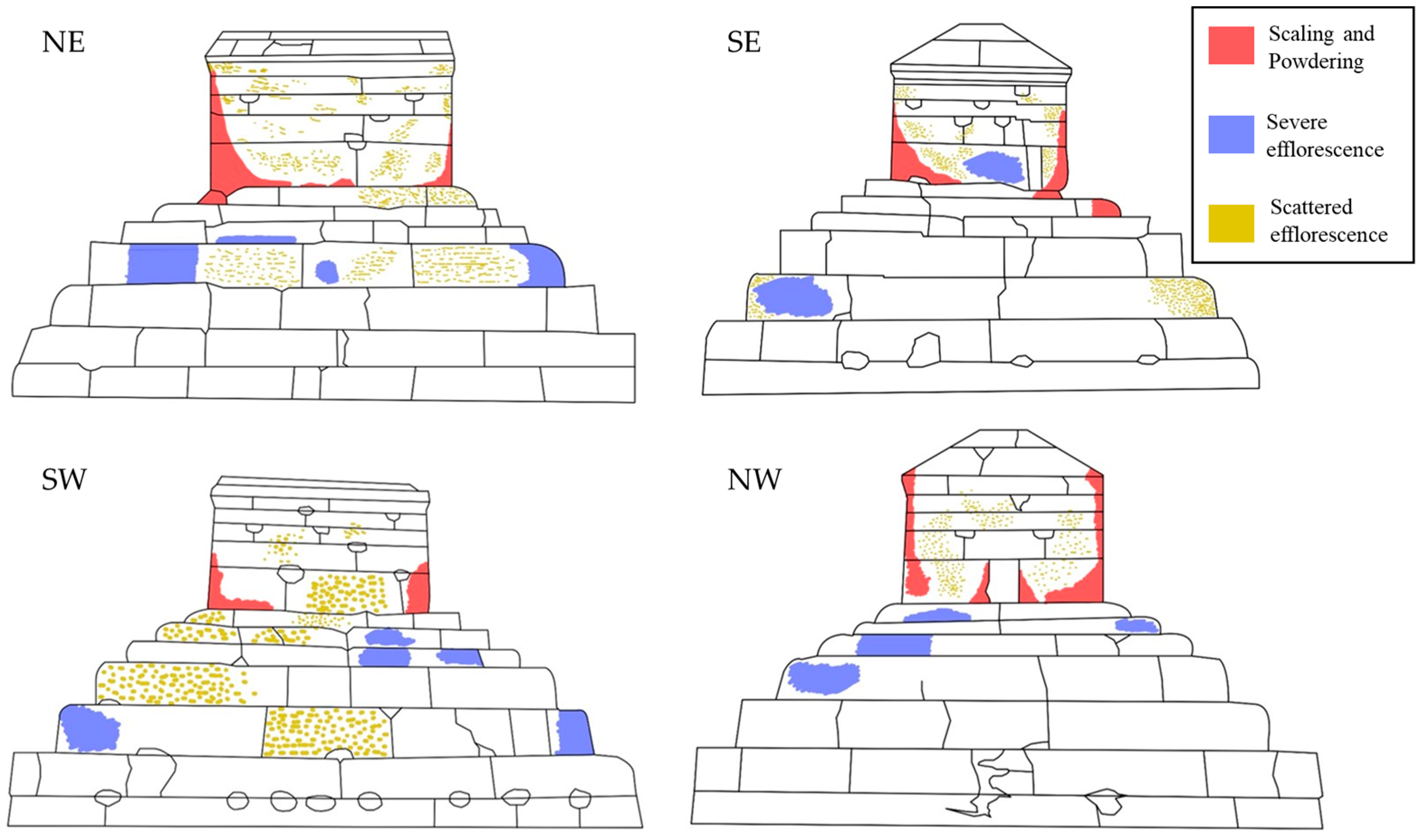
3.1. Previous Diagnosis of the Salt Problem

From the disaggregated stone material taken from the tomb, it was noted that there were certain amounts of the three anions analyzed: nitrate: 180 mg/kg; chloride: 85 mg/kg; and sulfate: 44 mg/kg. In addition, from the soil samples taken at 50 m and 120 m, it was noted that (1) the anionic contents were higher in the areas farthest from the tomb, except for nitrate, the concentrations of which were similar (5 mg/kg), and (2) the sulfate contents (2.3 mg/kg at 50 m and 7.7 mg/kg at 120 m) were much higher than those of chloride (1.2 mg/kg at 50 m and 1.5 mg/kg at 120 m).
Based on these data, it is confirmed that the presence of salts is one of the causes of the loss of material that can be seen on the surface of the monument. Regarding the origin, the content of nitrogen can be related to the use of fertilizers for farming around the tomb area over the ages (nitrogen is one of the main components of fertilizers [55]), the use of the surrounding areas to bury the dead, and the waste generated by animals during their passage through the Pasargadae area, which is documented in old photos. The sulfate could come from the leaching of part of the cement applied in previous interventions made in the tomb (interventions carried out before 1958 and in 2006) [45,56,57], the capillary rise of groundwater from areas where fertilizers were used [55,58], and also, according to [48], calcium sulfate can be formed by the secretion of inorganic sulfuric acid from fungi and its reaction with the calcite of the rock. With respect to chlorides, their origin could be anthropic and related to inappropriate restoration activities carried out in the past (for example, the use of cleaning products of polychromes and paints, such as potassium hypochlorite or hydrochloric acid). In all cases, the transport of salts by winds from the surrounding areas cannot be neglected, as this archaeological site was built in a geographically windy region.

3.2. Stone Properties

The XRD analyses showed that the beige limestone used in the construction of the tomb of Cyrus the Great is composed exclusively of calcite, with a low clay fraction composed of illite and chlorite. The chemical elements obtained via X-ray fluorescence (expressed as oxide weight (wt%)) were CaO (55.45%), MgO (0.33%), SiO2 (0.24%), Fe2O3 (0.13%), and SrO (0.05%). The loss on ignition at 950 °C was determined, which corresponded to the CaCO3 content (LOI950 (43.8%)).
Table 1 shows the main physical properties of the limestone. This stone has a high porosity (approximately 21%) and a low bulk density (1.74 g/cm3). Consequently, it can be classified, according to the American standard ASTM C568-79 [59], as a low-density limestone, which is prone to undergo weathering processes. This standard establishes three levels based on the bulk density (in g/cm3): low density: 1.76; medium density: 2.16; and high density: 2.56. The higher the bulk density, the lower the absorption capacity of the rock and the better its behavior against external alteration agents once it is put into service.
After the contamination cycles, the salt content increased significantly, the main ions being sulfate and chloride. This higher ionic content allowed for a more detailed analysis of the treatment efficacy.

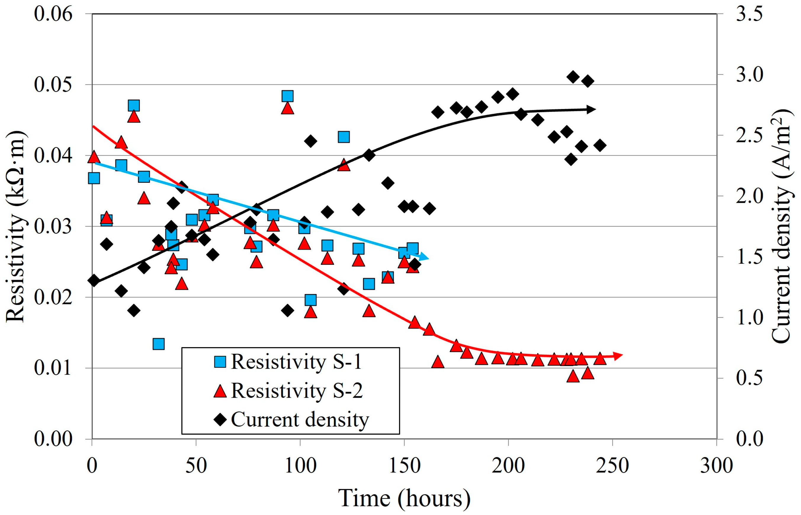
3.3. Evolution of the Electrical Parameters: Current Density and Resistivity

Figure 5 shows the variation in the current density and the resistivity of each limestone sample during the desalination test.
In the first 6 days (144 h), during which both samples were connected, a similar decrease in resistivity was observed in both samples. This trend is related to the mobilization of ions, which was similar in both samples. After this time, sample S-1 was disconnected from the system and replaced by a resistance of 10 kΩ. Thereafter, during the 7th day, a similar tendency to that of the previous days was observed (i.e., a decrease in the resistivity and increase in the current density). However, on the 8th day (192 h) and onwards, a stabilization of the current density and resistivity measurements (2.40 A·m−2 and 0.01 kΩ m, respectively) was observed. This fact could indicate the following: (1) The removal rate of the salts was slowing down due to the existence of a low ion content in sample S-2. In this case, the current transport seemed to be mainly produced by the ions of the supplied electrolyte. (2) The removal rate was slowing down but the salts were still being mobilized from the stone towards the poultice. This second hypothesis seems more logical, as the intensity readings were still very high and the resistance of the samples against the flow of this current had not started to increase.
In any case, the trend shown by the resistance measurements over time seems to indicate that the degree of desalination was higher in sample S-2 than in sample S-1, as an increased mobilization of ions took place over a longer period of time.

3.4. pH Measurements

The pH measurements registered with pH strips during the treatment showed the following: (1) in the vicinity of the electrodes, the pH values were extreme (4 at the anode and 12 at the cathode), due to the hydrolysis of water, and (2) on both surfaces of the samples, the pH values were close to neutrality (7–8), which shows that the buffer system used (electrolyte and poultices) allowed for buffering the pH variations that occurred in the vicinity of the electrodes, as has already been performed in other types of stones [31,33].
The pH values measured with a pH meter in the aqueous extractions of the prismatic samples again confirmed that the pH of the rock was not altered on either surface.

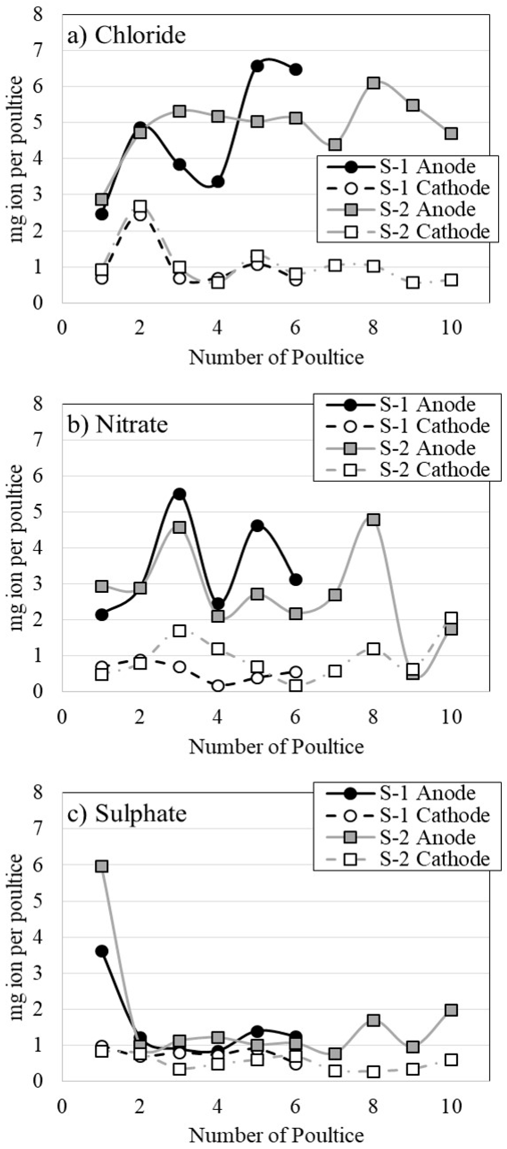
3.5. Anion Content Retained in the Poultices

Figure 6 shows the milligram per ion retained in each poultice after each application, and Table 2 shows the total quantity of each anion retained in each compartment at the end of the treatment.
In general, it was observed the following: (1) The highest extraction, in both samples and regardless of the anion analyzed, occurred in the poultices located at the anode, which is logical considering that anions are forced to migrate towards the anode under the influence of the electric field; (2) In each poultice application, a certain mobilization of the three anions towards the cathode was produced. This mobilization was practically constant throughout the treatment, with some exception, in which higher extractions were achieved, as in the case of chloride in the second application. This fact, according to [33,60], is related to the existence of diffusive processes, which try to maintain a chemical equilibrium in the setup, and advective processes, due to the suction exerted by the poultice used in the cathode during drying; (3) The removal rate of each anion was higher depending on its mobility and concentration in the material to be treated [33], a high concentration of ions with high mobility reduces the mobilization of those with lower mobility. For this reason, the highest extractions were achieved in chloride, followed by nitrate and sulfate; (4) The amount extracted increases with the number of applications, and it was therefore higher in sample S-2; (5) Desalination must not have been complete, as the difference between the anion content in the anode with respect to the cathode remained high, which indicates that there should still be a high anionic content, at least in the part of the samples closest to this electrode.
The analysis of the anion removal rates showed the following.
Regarding the chloride ion, despite the fluctuations detected in each poultice application, an upward trend in the extraction of this ion was seen, with a change in the trend occurring from the eighth application in sample S-2. However, despite a downward trend in the chloride extraction during the last applications, at the end of the treatment, the difference between the chloride content extracted between the anode and cathode remained high, indicating that there was still a very high concentration difference in the material.
As for the nitrate ion, the extractions achieved in both samples at the anode were similar and much higher than those achieved at the cathode, at least up to the eighth application in sample S-2. From the ninth application, the amount of nitrate extracted decreased until it was similar to that reached at the cathode, which could indicate that the amount of this anion that remains in sample S-2 is very low.
With regard to the sulfate ion, it was observed that, disregarding the extraction achieved in the first application, there was a general increasing trend at the anode. This may be related to a decrease in the content of more mobile ions, which favors an increase in the transport number of this anion. However, considering the low concentration of this ion in the anode poultice with respect to the other anions, and taking into account that sulfate was one of the main anions present at the beginning of the treatment in the rock (Table 1), this transport number is still very low.

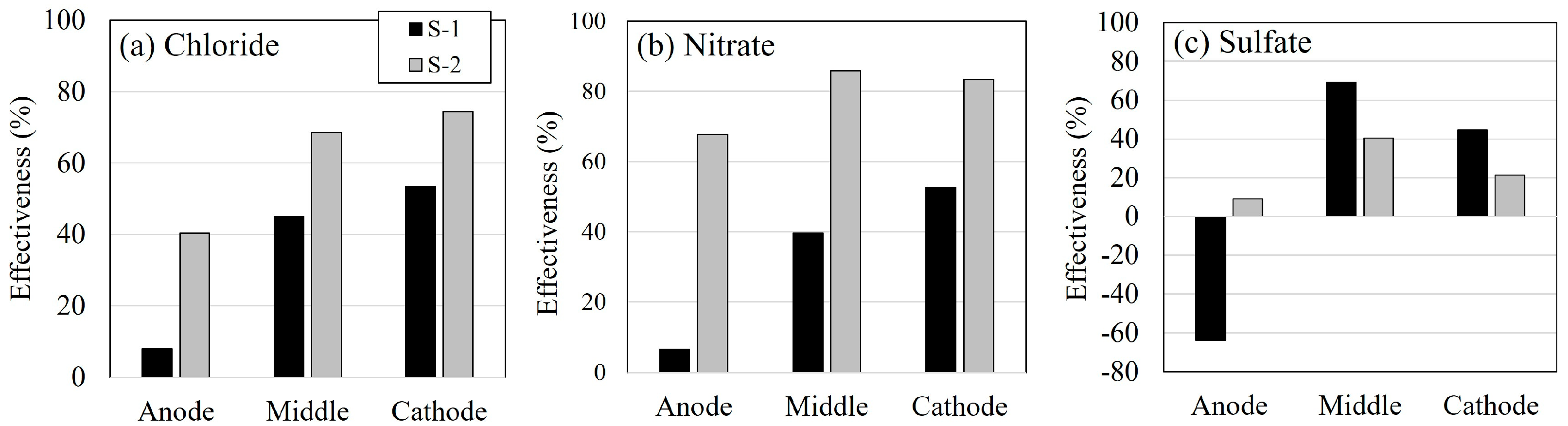
3.6. Desalination Effectiveness

Figure 7 shows the effectiveness percentages of the anion extraction at different depths (anode: 0–3.5 cm; middle: 3.5–6.5 cm; and cathode: 6.5–10 cm).
In general, regardless of the anion, the following was observed: (1) The effectiveness was higher in the middle and cathode zones than in the anode zones. This fact is related to the mobilization of the anions towards the anode during the desalination process, which is the area of the limestone sample in which the ions tended to accumulate to a greater extent; (2) The anion content in the anode areas tended to decrease as the treatment progressed. This can be seen both by the positive extraction percentages achieved with chloride and nitrate (more than 40% for Cl and 60% for NO3 in S-2, and less than 10% for both ions in S-1), and when comparing the enrichment of the sulfate ion in S-1 (effectiveness close to −60%) with the percentage of extraction achieved in S-2 (around 10%).
On average, the reduction in the ion content achieved in the limestone samples was improved when the treatment duration was increased, especially in the case of the highly mobile ions, such as chloride and nitrate (see Table 1). The average percentages of the extraction achieved for Cl and NO3 in sample S-2 were 61% and 79%, respectively, while in sample S-1, the percentages achieved were similar and close to 35%. This indicates that, as the content of the most mobile ion (chloride) is reduced, there is an increase in the removal rate of the other most mobile ion (nitrate) (i.e., its transport number during the electrokinetic process increases).
With respect to sulfate, the final average contents remaining in the limestone were similar in both samples (around 72–78 mg/kg (see Table 1)). This low difference is related to the content of the other ions still remaining in the stone, which therefore reduces the transport number of the sulfate ion (i.e., the mobilized amount of this anion is reduced because the other ions are the main carriers of the electric current). This means that it is necessary to increase the application time to reduce the Cl and NO3 contents and to increase the removal rate of SO42−. This fact could explain why, in sample S-2, a slight extraction was achieved in the anode zone by extracting the accumulation of the sulfate ions that tend to enrich it, as can be seen in sample S-1 (Figure 7).
This fact agrees with both (1) the resistance and intensity measurements, in which it was seen that the test was stopped too early to consider the high extraction percentages of all the salts present, and (2) the sulfate analyses executed on the poultices, in which it was seen that, in the last applications performed on sample S-2 (specifically from the eighth application onwards), a greater difference between the extraction achieved at the anode with respect to that achieved at the cathode was observed.

3.7. Possible Changes in the Stone

After the treatment, a slight decrease in the porosity and an increase in the bulk density of the desalinated samples were observed, especially in sample S-2 (Table 1). This fact is related to the buffer solution used in this study and the consequent electroprecipitation of the calcite inside the pores of the material.
During the pH buffering process, some of the calcium present in the anodic poultice is released and enters the limestone samples. This calcium tends to migrate to the cathode area due to the DC field action. During its mobilization, calcium can fix the OH groups, which are forced to migrate towards the anode, forming Portlandite (Ca(OH)2), as reported in previous studies [61,62]. This Portlandite can react with atmospheric CO2 to form calcite (the main component of limestone) [63,64,65,66]. This result is advantageous because it allows for recovering the cohesion of the limestone matrix and reducing the water absorption capacity of the rock, thereby increasing its mechanical resistance and durability against alteration caused by water or salts. In recent years, new treatments based on electroprecipitation have been developed to reduce the porosity of stony materials to make them less susceptible to weathering processes [67,68,69], or to provide them with new properties [70].
The results of the X-ray diffraction analysis performed at the end of the treatment on sample S-2 (Figure 8) are similar to those obtained from the original limestone sample. This fact corroborates that the treatment does not cause any chemical damage that could alter the crystalline phases present.
Hence, electrokinetic techniques can be considered a real alternative to intervening in the tomb due to the inexistent affection that this treatment has in this kind of stone.

4. Conclusions

The main conclusions drawn from this study are as follows:
  • The hypothesis that the Tomb of Cyrus is affected by the action of soluble salts, especially by the presence of nitrates and sulfates, is reaffirmed. For this reason, in the future, it is possible that the concentration may increase, and it will be necessary to consider an intervention strategy;
  • Electrokinetic techniques make it possible to achieve high desalination efficiency values in a short time. This efficiency can be increased by increasing the duration of the treatment;
  • The buffer system is effective at protecting limestone against extreme pH environments that can cause chemical damage;
  • The use of a calcium carbonate poultice at the anode allows for supplying calcium to the limestone, which can precipitate and evolve to calcium carbonate, causing a reduction in the accessible porosity of the stone.
To summarize, the effectiveness shown by the electrokinetic desalination method on this material and the possibility of limiting the possible harmful effects that the treatment may cause in the beige limestone, through the use of poultices and a buffer electrolyte, leads us to recommend the use of this technique as one of the most feasible solutions to carry out future interventions in the tomb to reduce the ion content.
In this sense, and as a guide for future application, the use of electrokinetic devices that can house both the electrodes and the poultices with a composition similar to that shown in this study is recommended. The devices should be placed in parallel on the same surface, alternating the anodes with the cathodes, with a separation between them of approximately 50 cm. This allows the electric field to penetrate to a depth of approximately 10 cm (one-fifth of the separation between the devices).
To favor desalination and to prevent the drying of the materials, which could hinder the extraction process, due to the high temperatures that can be reached at the Pasargadae site, the use of a sprinkler irrigation system that periodically moistens both the stone and the poultices is recommended. In addition to this system, it is advisable to carry out a periodical renewal of the poultices to improve the desalination process.
The total time of the application of the treatment is determined via the periodic analyses carried out on the poultices. As soon as the concentrations between the anode and cathode in the poultices are similar, the treatment can be considered finished.

Author Contributions

Conceptualization, N.E. and J.F.; investigation, N.E.; methodology, J.F.; formal analysis, N.E., J.F. and N.A.; resources, N.E.; writing—original draft preparation, N.E., J.F. and N.A.; funding acquisition, N.E.; supervision, J.F. All authors have read and agreed to the published version of the manuscript.

Funding

This research received no external funding.

Data Availability Statement

The data used in this study are confidential.

Acknowledgments

Special acknowledgment is given to the professional support provided by the Defense University Center at the Spanish Naval Academy (CUD-ENM).

Conflicts of Interest

The authors declare no conflict of interest.

References

  1. Charola, A.E. Salts in the Deterioration of Porous Materials: An Overview. J. Am. Inst. Conserv. 2000, 39, 327–343. [Google Scholar] [CrossRef]
  2. Charola, A.E.; Pühringer, J.; Steiger, M. Gypsum: A review of its role in the deterioration of building materials. Environ. Geol. 2007, 52, 339–352. [Google Scholar] [CrossRef]
  3. Oguchi, C.T.; Yu, S. A review of theoretical salt weathering studies for stone heritage. Prog. Earth Planet. Sci. 2021, 8, 32. [Google Scholar] [CrossRef]
  4. Arnold, A.; Zehnder, K. Salt weathering on monuments. In Proceedings of the 1st International Symposium on the Conservation of Monuments in the Mediterranean Basin, Bari, Italy, 7–10 June 1989. [Google Scholar]
  5. Alves, C.; Figueiredo, C.A.M.; Sanjurjo-Sánchez, J.; Hernández, A.C. Salt weathering of natural stone: A review of comparative laboratory studies. Heritage 2021, 4, 1554–1565. [Google Scholar] [CrossRef]
  6. La Iglesia, A.; González, V.; López-Acevedo, V.; Viedma, C. Salt crystallization in porous construction materials I Estimation of crystallization pressure. J. Cryst. Growth 1997, 177, 111–118. [Google Scholar] [CrossRef]
  7. Tsui, N.; Flatt, R.J.; Scherer, G.W. Crystallization damage by sodium sulfate. J. Cult. Herit. 2003, 4, 109–115. [Google Scholar] [CrossRef]
  8. Lubelli, B.; Van Hees, R.P.J.; Groot, C.J.W.P. The role of sea salts in the occurrence of different damage mechanisms and decay patterns on brick masonry. Constr. Build. Mater. 2004, 18, 119–124. [Google Scholar] [CrossRef]
  9. Steiger, M. Crystal growth in porous materials—I: The crystallization pressure of large crystals. J. Cryst. Growth 2005, 282, 455–469. [Google Scholar] [CrossRef]
  10. Steiger, M. Crystal growth in porous materials—II: Influence of crystal size on the crystallization pressure. J. Cryst. Growth 2005, 282, 470–481. [Google Scholar] [CrossRef]
  11. Scherer, G.W. Crystallization in pores. Cem. Concr. Res. 1999, 29, 1347–1358. [Google Scholar] [CrossRef]
  12. Lopez-Arce, P.; Doehne, E.; Greenshields, J.; Benavente, D.; Young, D. Treatment of rising damp and salt decay: The historic masonry buildings of Adelaide, South Australia. Mater. Struct. 2008, 42, 827–848. [Google Scholar] [CrossRef]
  13. Rivas, T.; Feijoo, J.; de Rosario, I.; Taboada, J. Use of Ferrocyanides on Granite Desalination by Immersion and Poultice-Based Methods. Int. J. Archit. Herit. 2017, 11, 588–606. [Google Scholar] [CrossRef]
  14. Unruh, J. A Revised Endpoint for Ceramics Desalination at the Archaeological Site of Gordion, Turkey. Stud. Conserv. 2007, 46, 81. [Google Scholar] [CrossRef]
  15. Husillos-Rodríguez, N.; Carmona-Quiroga, P.M.; Martínez-Ramírez, S.; Blanco-Varela, M.T.; Fort, R. Sacrificial mortars for surface desalination. Constr. Build. Mater. 2018, 173, 452–460. [Google Scholar] [CrossRef]
  16. Feijoo, J.; Ergenç, D.; Fort, R.; de Buergo, M.Á. Addition of ferrocyanide-based compounds to repairing joint lime mortars as a protective method for porous building materials against sodium chloride damage. Mater. Struct. Constr. 2021, 54, 14. [Google Scholar] [CrossRef]
  17. Lubelli, B.; van Hees, R.P.J. Desalination of masonry structures: Fine tuning of pore size distribution of poultices to substrate properties. J. Cult. Herit. 2010, 11, 10–18. [Google Scholar] [CrossRef]
  18. Pel, L.; Sawdy, A.; Voronina, V. Physical principles and efficiency of salt extraction by poulticing. J. Cult. Herit. 2010, 11, 59–67. [Google Scholar] [CrossRef]
  19. Petković, J.; Huinink, H.P.; Pel, L.; Kopinga, K.; van Hees, R.P.J. Salt transport in plaster/substrate layers. Mater. Struct. 2007, 40, 475–490. [Google Scholar] [CrossRef]
  20. Correia, J.; Matero, F. Calcium tartrate tetrahydrate preconsolidation of salt-contaminated limestone at mission San José y San Miguel de Aguayo. J. Am. Inst. Conserv. 2008, 47, 81–95. [Google Scholar] [CrossRef]
  21. Feijoo, J.; de Rosario, I.; Rivas, T.; Mosquera, M.J.; Benavides, R. Influence of a Pre-consolidation Treatment on the Desalination Effectiveness of a Highly Deteriorated Granite Façade of Medieval Age. Int. J. Archit. Herit. 2022, 1–19. [Google Scholar] [CrossRef]
  22. Sawdy, A.; Heritage, A.; Pel, L. A review of salt transport in porous media: Assessment methods and salt reduction treatments. In Proceedings of the Salt Weathering on Buildings and Stone Sculptures, Copenhagen, Denmark, 22–24 October 2008. [Google Scholar]
  23. Gupta, S.; Pel, L.; Steiger, M.; Kopinga, K. The effect of ferrocyanide ions on sodium chloride crystallization in salt mixtures. J. Cryst. Growth 2015, 410, 7–13. [Google Scholar] [CrossRef]
  24. Gupta, S.; Terheiden, K.; Pel, L.; Sawdy, A. Influence of ferrocyanide inhibitors on the transport and crystallization processes of sodium chloride in porous building materials. Cryst. Growth Des. 2012, 12, 3888–3898. [Google Scholar] [CrossRef]
  25. Granneman, S.J.C.; Lubelli, B.; van Hees, R.P.J. Mitigating salt damage in building materials by the use of crystallization modifiers—A review and outlook. J. Cult. Herit. 2019, 40, 183–194. [Google Scholar] [CrossRef]
  26. Bracciale, M.P.; Sammut, S.; Cassar, J.A.; Santarelli, M.L.; Marrocchi, A. Molecular crystallization inhibitors for salt damage control in porous materials: An overview. Molecules 2020, 25, 1873. [Google Scholar] [CrossRef] [PubMed]
  27. Ottosen, L.M.; Rörig-Dalgård, I. Electrokinetic removal of Ca(NO3)2 from bricks to avoid salt-induced decay. Electrochim. Acta 2007, 52, 3454–3463. [Google Scholar] [CrossRef]
  28. Ottosen, L.M.; Rörig-Dalgaard, I. Desalination of a brick by application of an electric DC field. Mater. Struct. 2009, 42, 961–971. [Google Scholar] [CrossRef]
  29. Skibsted, G.; Ottosen, L.M.; Jensen, P.E.; Paz-Garcia, J.M. Electrochemical desalination of bricks—Experimental and modeling. Electrochim. Acta 2015, 181, 24–30. [Google Scholar] [CrossRef]
  30. Marinho, J.N.; Salavessa, E.; Jalali, S.; Sousa, L.; Serôdio, C.; Carvalho, M.J.P. Evaluation of Electromigration Desalination of Granite Contaminated with Salts—A Contribution to the Conservation of Architectural Surfaces. In Proceedings of the 3rd RILEM Spring Convention and Conference (RSCC 2020), Guimarães, Portugal, 9–14 March 2020; Sena-Cruz, J., Correia, L., Azenha, M., Eds.; Springer International Publishing: Cham, Switzerland, 2022; pp. 217–228. [Google Scholar] [CrossRef]
  31. Feijoo, J.; Ottosen, L.M.; Pozo-Antonio, J.S. Influence of the properties of granite and sandstone in the desalination process by electrokinetic technique. Electrochim. Acta 2015, 181, 280–287. [Google Scholar] [CrossRef]
  32. Ottosen, L.M.; Christensen, I.V. Electrokinetic desalination of sandstones for NaCl removal—Test of different clay poultices at the electrodes. Electrochim. Acta 2012, 86, 192–202. [Google Scholar] [CrossRef]
  33. Feijoo, J.; Matyščák, O.; Ottosen, L.M.; Rivas, T.; Nóvoa, X.R. Electrokinetic desalination of protruded areas of stone avoiding the direct contact with electrodes. Mater. Struct. Constr. 2017, 50, 82. [Google Scholar] [CrossRef]
  34. Ottosen, L.M. Electro-Desalination of Sandstones with Cracks. In Proceedings of the XV Edition of the International Conference on Durability of Building Materials and Components, Barcelona, Spain, 20–23 October 2020; International Center for Numerical Methods in Engineering: Barcelona, Spain, 2020; pp. 1173–1180. [Google Scholar] [CrossRef]
  35. Matyščák, O.; Ottosen, L.M.; Rörig-Dalgaard, I. Desalination of salt damaged Obernkirchen sandstone by an applied DC field. Comput. Chem. Eng. 2014, 71, 561–569. [Google Scholar] [CrossRef]
  36. Ottosen, L.M.; Pedersen, A.J.; Rörig-Dalgaard, I. Salt-related problems in brick masonry and electrokinetic removal of salts. J. Build. Apprais. 2007, 3, 181–194. [Google Scholar] [CrossRef]
  37. Ottosen, L.M.; Rörig-dalgaard, I.; Villumsen, A. Electrochemical removal of salts from masonry—Experiences from pilot scale. In Proceedings of the International Conference on Salt Weathering on Building and Stone Sculptures, Copenhagen, Denmark, 22 October 2008. [Google Scholar]
  38. Feijoo, J.; Ottosen, L.M.; Matyscak, O.; Fort, R. Electrokinetic desalination of a farmhouse applying a proton pump approach. First in situ experience. Constr. Build. Mater. 2020, 243, 118308. [Google Scholar] [CrossRef]
  39. Feijoo, J.; Rivas, T.; Nóvoa, X.R.; de Rosario, I.; Otero, J. In situ desalination of a granitic column by the electrokinetic method. Int. J. Archit. Herit. 2018, 12, 63–74. [Google Scholar] [CrossRef]
  40. Ottosen, L.M.; Christensen, I.V.; Rörig-dalgaard, I. Electrochemical Desalination of Salt Infected Limestone Masonry of a Historic Warehouse. In Proceedings of the Structural Faults and Repair, Edinburg, UK, 3–5 July 2012. [Google Scholar]
  41. Kamran, K.; van Soestbergen, M.; Huinink, H.P.; Pel, L. Inhibition of electrokinetic ion transport in porous materials due to potential drops induced by electrolysis. Electrochim. Acta 2012, 78, 229–235. [Google Scholar] [CrossRef]
  42. Liu, Y.; Shi, X. Ionic transport in cementitious materials under an externally applied electric field: Finite element modeling. Constr. Build. Mater. 2012, 27, 450–460. [Google Scholar] [CrossRef]
  43. Li, C.; Man, H.; Song, C.; Gao, W. Fracture analysis of piezoelectric materials using the scaled boundary finite element method. Eng. Fract. Mech. 2013, 97, 52–71. [Google Scholar] [CrossRef]
  44. Zhang, T.Y.; Gao, C.F. Fracture behaviors of piezoelectric materials. Theor. Appl. Fract. Mech. 2004, 41, 339–379. [Google Scholar] [CrossRef]
  45. Fanood, M.R.; Saradj, F.M. Learning from the past and planning for the future: Conditions and proposals for stone conservation of the mausoleum of Cyrus the Great in the World Heritage site of Pasargadae. Int. J. Archit. Herit. 2013, 7, 434–460. [Google Scholar] [CrossRef]
  46. Mohammadi, P.; Maghboli-Balasjin, N. Isolation and molecular identification of deteriorating fungi from cyrus the great tomb stones. Iran. J. Microbiol. 2014, 6, 361–370. [Google Scholar] [CrossRef]
  47. Shekofteh, A.; Molina Piernas, E.; Arizzi, A.; Cultrone, G.; Ahmadi, H.; Yazdi, M. Deterioration assessment of three types of limestones from Pasargadae world heritage site in Iran. In Proceedings of the Youth in Conservation of Cultural Heritage—YOCOCU, Madrid, Spain, 21–23 September 2016; pp. 72–76. [Google Scholar]
  48. Shekofteh, A.; Molina, E.; Arizzi, A.; Cultrone, G.; Ahmadi, H.; Yazdi, M. Characterization and damage assessment of stones used in the Pasargadae World Heritage Site, Achaemenian period. Int. J. Archit. Herit. 2019, 13, 521–536. [Google Scholar] [CrossRef]
  49. Gholipour-Shahraki, M.; Mohammadi, P. The Study of Growth of Calogaya sp. PLM8 on Cyrus the Great’s Tomb, UNESCO World Heritage Site in Iran. Int. J. Environ. Res. 2017, 11, 501–513. [Google Scholar] [CrossRef]
  50. Sohrabi, M.; Favero-Longo, S.E.; Pérez-Ortega, S.; Ascaso, C.; Haghighat, Z.; Talebian, M.H.; Fadaei, H.; de los Ríos, A. Lichen colonization and associated deterioration processes in Pasargadae, UNESCO world heritage site, Iran. Int. Biodeterior. Biodegrad. 2017, 117, 171–182. [Google Scholar] [CrossRef]
  51. Mozaffari, A. World Heritage in Iran: Perspectives on Pasargadae; Ashgate Publishing: Farnham, UK, 2014. [Google Scholar]
  52. UNE-EN 1936:2007; Natural Stone Test Methods—Determination of Real Density and Apparent Density, and of Total and Open Porosity. UNE: Madrid, Spain, 2007.
  53. Rörig-Dalgaard, I. Development of a poultice for electrochemical desalination of porous building materials: Desalination effect and pH changes. Mater. Struct. 2013, 46, 959–970. [Google Scholar] [CrossRef]
  54. Castellote, M.; Andrade, C.; Alonso, C. Electrochemical removal of chlorides Modelling of the extraction, resulting profiles and determination of the efficient time of treatment. Cem. Concr. Res. 2000, 30, 615–621. [Google Scholar] [CrossRef]
  55. Grossi, C.M.; Esbert, R.M. Las sales solubles en el deterioro de rocas monumentales. Revisión bibliográfica. Mater. Construcción 1994, 44, 15–30. [Google Scholar] [CrossRef]
  56. Kloppmann, W.; Bromblet, P.; Vallet, J.M.; Vergès-Belmin, V.; Rolland, O.; Guerrot, C.; Gosselin, C. Building materials as intrinsic sources of sulphate: A hidden face of salt weathering of historical monuments investigated through multi-isotope tracing (B, O, S). Sci. Total Environ. 2011, 409, 1658–1669. [Google Scholar] [CrossRef] [PubMed]
  57. Silva, B.; Prieto, B.; Rivas, T.; Pereira, L. Gypsum-induced decay in granite monuments in Northwestern Spain. Mater. Constr. 2010, 60, 97–110. [Google Scholar] [CrossRef]
  58. Jiang, Y. Sources of sulfur in the Nandong underground river system, southwest China: A chemical and isotopic reconnaissance. Appl. Geochem. 2012, 27, 1463–1470. [Google Scholar] [CrossRef]
  59. C568-79; ASTM Anual Book of ASTM Standrads. Part 19. Soil and Rock. Building Stones. ASTM: West Conshohocken, PA, USA, 1981.
  60. Ottosen, L.M.; Christensen, I.V.; Rörig-Dalgård, I.; Jensen, P.E.; Hansen, H.K. Utilization of electromigration in civil and environmental engineering—Processes, transport rates and matrix changes. J. Environ. Sci. Health—Part A Toxic/Hazard. Subst. Environ. Eng. 2008, 43, 795–809. [Google Scholar] [CrossRef]
  61. Paz-García, J.M.; Johannesson, B.; Ottosen, L.M.; Alshawabkeh, A.N.; Ribeiro, A.B.; Rodríguez-Maroto, J.M. Modeling of electrokinetic desalination of bricks. Electrochim. Acta 2012, 86, 213–222. [Google Scholar] [CrossRef]
  62. Ottosen, L.M.; Ferreira, C.M.D.; Christensen, I.V. Electrokinetic desalination of glazed ceramic tiles. J. Appl. Electrochem. 2010, 40, 1161–1171. [Google Scholar] [CrossRef]
  63. Cizer, Ö.; Rodriguez-Navarro, C.; Ruiz-Agudo, E.; Elsen, J.; Van Gemert, D.; Van Balen, K. Phase and morphology evolution of calcium carbonate precipitated by carbonation of hydrated lime. J. Mater. Sci. 2012, 47, 6151–6165. [Google Scholar] [CrossRef]
  64. Beruto, D.T.; Botter, R. Liquid-like H2O adsorption layers to catalyze the Ca(OH)2/CO2 solid-gas reaction and to form a non-protective solid product layer at 20 °C. J. Eur. Ceram. Soc. 2000, 20, 497–503. [Google Scholar] [CrossRef]
  65. Gu, W.; Bousfield, D.W.; Tripp, C.P. Formation of calcium carbonate particles by direct contact of Ca(OH)2 powders with supercritical CO2. J. Mater. Chem. 2006, 16, 3312–3317. [Google Scholar] [CrossRef]
  66. Vance, K.; Falzone, G.; Pignatelli, I.; Bauchy, M.; Balonis, M.; Sant, G. Direct Carbonation of Ca(OH)2 Using Liquid and Supercritical CO2: Implications for Carbon-Neutral Cementation. Ind. Eng. Chem. Res. 2015, 54, 8908–8918. [Google Scholar] [CrossRef]
  67. Feijoo, J.; Fort, R.; Gomez-Villalba, L.S.; Rabanal, M.E.; Ottosen, L.M. Electroprecipitation of Magnesium and Calcium Compounds for Weathering Protection of Ornamental Rocks. Cryst. Growth Des. 2020, 20, 2337–2355. [Google Scholar] [CrossRef]
  68. Sassoni, E.; Masi, G.; Bignozzi, M.; Franzoni, E. Electrodeposition of Hydroxyapatite Coatings for Marble Protection: Preliminary Results. Coatings 2019, 9, 207. [Google Scholar] [CrossRef]
  69. Meloni, P.; Manca, F.; Carcangiu, G. Marble protection: An inorganic electrokinetic approach. Appl. Surf. Sci. 2013, 273, 377–385. [Google Scholar] [CrossRef]
  70. Feijoo, J.; Gomez-Villalba, L.S.; de los Ríos, A.; Fort, R. Electroprecipitation of inorganic borates, with different solubility, within monumental stones to avoid fungal colonization. Constr. Build. Mater. 2023, 368, 130435. [Google Scholar] [CrossRef]
Figure 1. General view of the Tomb of Cyrus made completely from beige limestone slabs beside each other without the use of mortar (a). Photography of powdering and scaling of the stone surface caused by soluble salts (b).
Heritage 06 00365 g001
Figure 2. Location of Pasargadae located in the southern region of Iran (a). Aerial view of the archaeological site of Pasargadae on which the location of the Tomb of Cyrus is indicated in red (b).
Heritage 06 00365 g002
Figure 3. The weathering-form map obtained from the visual inspection, possibly associated with the presence of soluble salts on each facade of the monument.
Heritage 06 00365 g003
Figure 4. Schematic view (a) and picture (b) of the desalination setup. The compartments of the system filled with poultices (A and C) used to desalinate two limestone samples (S-1 and S-2) simultaneously with a power supply connected using graphite electrodes (E). The samples and the resistance (R) are connected in series to the system.
Heritage 06 00365 g004
Figure 5. Evolution of the resistivity measurements (in kΩ·m) exerted by the limestone samples (S-1: blue squares; S-2: red triangles) and current density (black diamonds, in A·m−2) flowing through the circuit during the treatment.
Heritage 06 00365 g005
Figure 6. Anion contents (chloride, nitrate, and sulfate) retained in each poultice renewal during the desalination of limestone samples S-1 and S-2 at the anode (solid lines) and cathode (dashed lines).
Heritage 06 00365 g006
Figure 7. Effectiveness (in %) of the different anions analyzed: chloride (a), nitrate (b), and sulfate (c), reached in the different parts in which the prismatic limestone samples were divided (close to the anode, the middle, and close to the cathode).
Heritage 06 00365 g007
Figure 8. XRD profile of beige limestone after the treatment showing intensity maxima of calcite in red.
Heritage 06 00365 g008
Table 1. Porosity and bulk density of the beige limestone used in the Tomb of Cyrus. Also, the initial and final average anion contents (in mg/kg) in the limestone samples are shown.
Physical PropertiesBefore TreatmentAfter Treatment
S-1S-2
Porosity (%)20.9012.0010.00
Bulk density (g/cm3)1.742.052.14
Average Anion Content (mg/kg)Before TreatmentAfter Treatment
S-1S-2
NO372.6548.7215.18
SO42−94.0078.3371.85
Cl98.2563.3738.24
Table 2. Total contents of each ion, in mg, retained in the poultices used in each electrode compartment (anode and cathode) and total anion content removed from each limestone sample.
AnionAnodeCathodeTotal
S-1S-2S-1S-2S-1S-2
Chloride27.749.06.310.634.059.6
Nitrate20.827.23.59.624.336.8
Sulfate9.316.94.65.313.922.2
Disclaimer/Publisher’s Note: The statements, opinions and data contained in all publications are solely those of the individual author(s) and contributor(s) and not of MDPI and/or the editor(s). MDPI and/or the editor(s) disclaim responsibility for any injury to people or property resulting from any ideas, methods, instructions or products referred to in the content.

