Article

Study on Fluid–Structure Interaction of a Camber Morphing Wing

China Aerodynamics Research and Development Center, Institute of High Speed Aerodynamics, Mianyang 621000, China
*
Author to whom correspondence should be addressed.
Vibration 2023, 6(4), 1060-1074; https://doi.org/10.3390/vibration6040062
Submission received: 14 October 2023 / Revised: 17 November 2023 / Accepted: 22 November 2023 / Published: 12 December 2023

Abstract

:
The influence of trailing edge deformation on the aerodynamic characteristics of camber morphing wings is an important topic in the aviation field. In this paper, a new memory alloy actuator is proposed to realize trailing edge deformation, and computational fluid dynamics (CFD) and wind tunnel experiments are used to study the influence of trailing edge deformation on the aerodynamic characteristics of the camber morphing wings. The experiments was carried out in a transonic wind tunnel with Mach numbers ranging from 0.4 to 0.8 and angles of attack ranging from 0° to 6°. The external flow fields and aerodynamic force coefficients with and without deformation were calculated using the CFD method. A loose coupled method based on data exchange was used to achieve a fluid–structure interaction (FSI) analysis. The research results indicate that when the trailing edge is deflected downwards, the phenomenon of shock wave forward movement reduces the negative pressure area on the upper wing surface, increases the pressure on the lower wing surface, and ultimately increases the total lift. This work provides a new approach for the implementation of trailing edge deformation and a powerful data reference for the design of camber morphing wings.

1. Introduction

The next generation of aircrafts [1] should have the ability to independently perform multiple tasks, such as takeoff and landing, cruising, maneuvering, hovering, and attacking, with optimal aerodynamic performance under variable flight conditions. Therefore, the concept of adaptive wing configuration, similar to that of birds [2], holds promise, from which the idea of morphing wings was born [3]. In the field of engineering, morphing bodies refer to the fact that vehicles can continuously change their configurations, which are known as morphing wings, for stepless speed regulation of their driving mechanism [4].
The complexity and variability of the flight environment [5], flow parameters (such as Reynolds number, Mach number, etc.), and real-time adjustments of the aerodynamic configuration can lead to flow instability [6], which results in significant time variance and nonlinearity of its aerodynamic characteristics after the wing configuration changes [7]. This can make it difficult for the wing to maintain optimal aerodynamic characteristics and may even pose a threat to flight safety [8]. For example, the upper surfaces of supercritical wings of large transport aircraft are prone to the phenomenon of shock/boundary layer interaction, which is extremely sensitive to transonic flight conditions. If the wing deformation cannot accurately respond to this flow phenomenon [9], then it not only fails to improve cruise efficiency but may also exacerbate the shock/boundary layer interaction and jeopardize flight safety. In addition, smart actuator materials typically exhibit nonlinear characteristics [10]. For instance, the recovery stress of shape memory alloys increases with the increasing temperature, but this pattern exhibits prominent nonlinear characteristics. The nonlinearity of the output force of the actuator material will add nonlinear characteristics to the aerodynamic forces during morphing [11]. Under such complex multi-force coupling, the structural deformation response will become difficult to judge. At the same time, structural deformation responses can, in turn, affect the aerodynamic forces and driving forces, which makes the problem more complicated.
The above analysis shows that the complexity of the flow around a deformable wing at high speeds [12], the coupling between smart driving materials, and the structural deformation responses increase the difficulty of accurately grasping the aerodynamic characteristics and structural deformation. Therefore, it is necessary to conduct high-speed wind tunnel tests and fluid–structure interaction calculations for morphing aircrafts [13], which will help to reveal the flow phenomena and mechanisms, promote the development of wind tunnel tests and numerical simulation techniques, and accelerate the practical applications for morphing wings [14].
One approach that has been applied is to obtain aerodynamic forces by changing the configuration of supercritical wings [15]. For example, foldable wings based on structures of bat or bird wings were designed by Clement Ader. The wing area can be reduced by one-third or even half. In order to achieve such a large area change, designers used flexible skin, but this type of skin has a small elastic modulus and insufficient stiffness. Under slightly larger aerodynamic loads, the skin will deform and cannot maintain its shape [16]. Furthermore, an insufficient elastic modulus can also lead to low tensile, bending, and shear strengths of the skin, thereby limiting flight speed. The application of morphing wing technology [17] represents a compromise between rigid and flexible structures because of the high-speed aerodynamic loads acting on the traditional flexible skin [18]. Moreover, the traditional drive method has a small power-to-weight ratio. The aerodynamic benefits brought about by complex drive mechanisms cannot compensate for the disadvantages caused by the excessive mechanism weight [19]. With the continuous development of materials science, the emergence of smart materials brings hope for solving these problems. Drives based on smart materials [20] often have larger power-to-weight ratios, higher energy efficiency levels, and better volumetric efficiency. The drive structure comprises a simplified smart material and the weight of the drive mechanism is reduced by using this new material [15]. Various drive structures can be designed to achieve complex and diverse configuration changes while meeting the volume, weight, and stability requirements. Smart materials act as sensors and controllers [21] while being a part of the structure [22]. Specifically, smart materials can serve as skins, beams, or ribs for wing structures. They cannot only withstand aerodynamic loads but also drive the wing’s deformation [23] according to the control signals. Therefore, morphing wings based on smart materials have gradually become a hot research topic. In the design phase, the aerodynamic data can be acquired via wind tunnel testing or the CFD method [19], and then the control system can be checked. The trailing edge of the morphing wing is deformed by a kind of flexible structure, which can control the influences of aeroelastic deformation and structural resistance. Therefore, the morphing wing mechanics model involves the coupling among aerodynamics [24], structural forces, and driving forces. At low-speed flight conditions, the influence of the aerodynamic forces can be ignored, and the change in the aerodynamic configuration is only the result of structural forces and driving forces. The aerodynamic forces and structural deformation are decoupled [25], and the system model is relatively simple. By using this model, satisfactory results can be obtained for a finite element analysis and CFD calculation. However, in high-speed flight conditions, it is necessary to consider the coupling between the three forces. Therefore, research should be carried out through fluid–structure interaction analysis or wind tunnels experiments [26].
With the rapid development of materials science, shape memory alloy (SMA) actuators with the shape memory effect (SME) are coming to be widely used in the aviation field. In general, an SMA actuator consists of a driver section and an execution section. The working principle of the SMA actuator is that when the SMA springs are heated, their material structure undergoes a phase transformation, and their shape-restoring force overcomes the spring tension and generates action. It should be noted that an SMA can generate significant restoring force during deformation process. Due to their high power-to-weight ratio, small size, and simple structure, shape memory alloy actuators are commonly used as one of the preferred actuators for wing variant structure. Lv et al. [15] proposed a smart structure based on a shape memory alloy for driving the morphing trailing edge, which was validated in a transonic wind tunnel. In 2023, Grigorie et al. [27] developed an automatic control technology for an SMA-based actuation system. So, it is evident that SMA actuators have tremendous potential in the aviation industry.
In this work [28], the influence of trailing edge deflecting is investigated. Firstly, the SMA-based actuation method to deflect the trailing edge of a supercritical airfoil was studied [29]. Subsequently, a coupling analysis between the aerodynamic and structural model was carried out. A wind tunnel model [30] was manufactured, which can satisfy the requirements of high-speed wind tunnel tests. The numerical and experimental results were analyzed. In this way, the relationship between the aerodynamic forces, structural deformation, and control forces of the morphing wings was ascertained.
In summary, in order to improve the safety and reliability of morphing wings, it is necessary to study their aerodynamic characteristics and structural deformation delicately. Therefore, in this study, both finite element simulation and wind tunnel experiments were used to explore the influence of trailing edge deformation on important parameters such as pressure distribution, vorticity distribution, Mach number distribution, trailing edge lift, etc., for their potential to further reduce the weight of the wings and improve the power-to-weight ratio. This work proposes a memory-alloy-based actuator to drive trailing edge deformation, and it assists us to further understand the fluid–structure interaction characteristics of deformable wings at high speeds, as well as the coupling relationship between smart driving material characteristics and the structural deformation response. It also lays the foundation for future research on deformable wings and accelerates the practical application of such wing engineering.

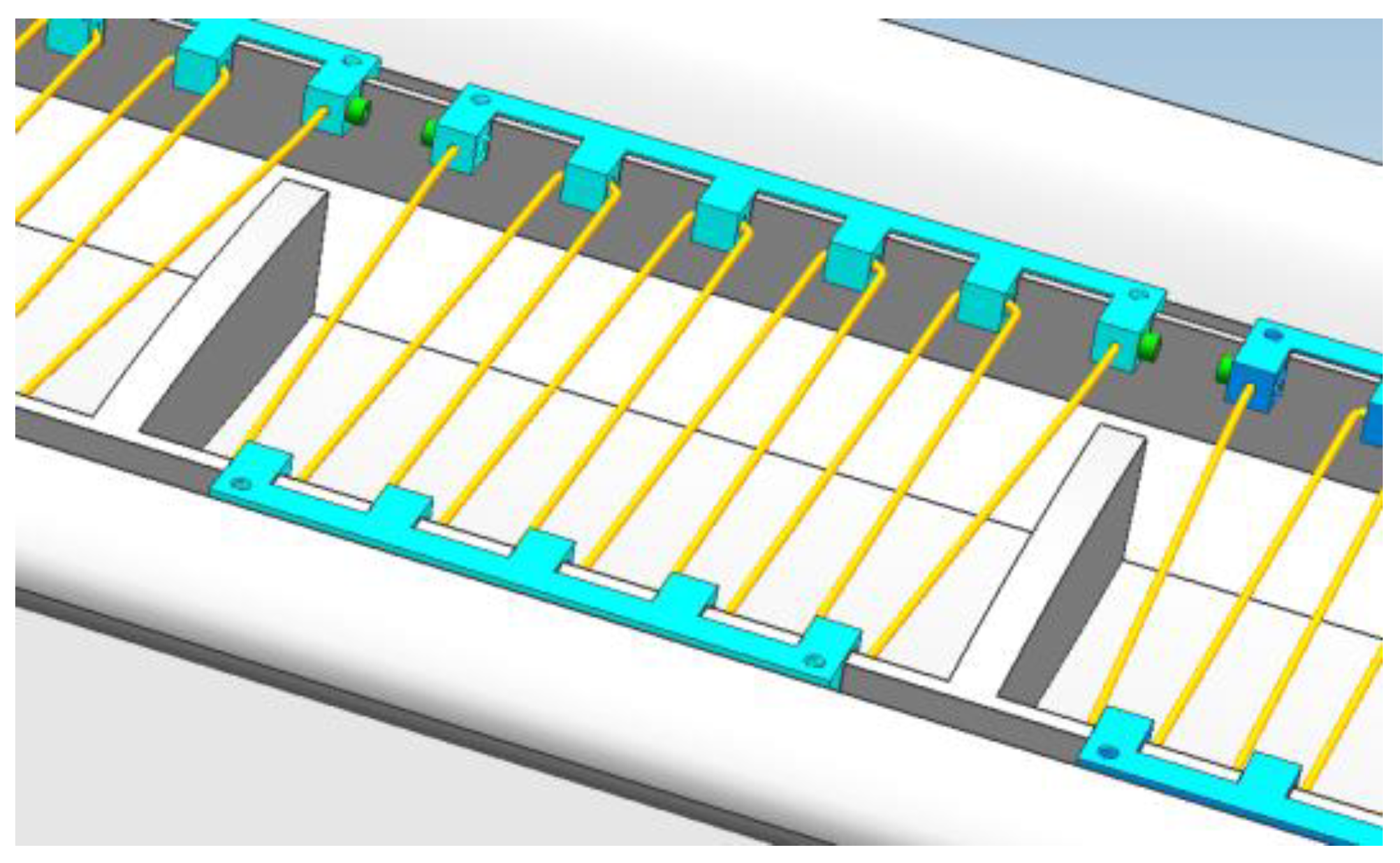
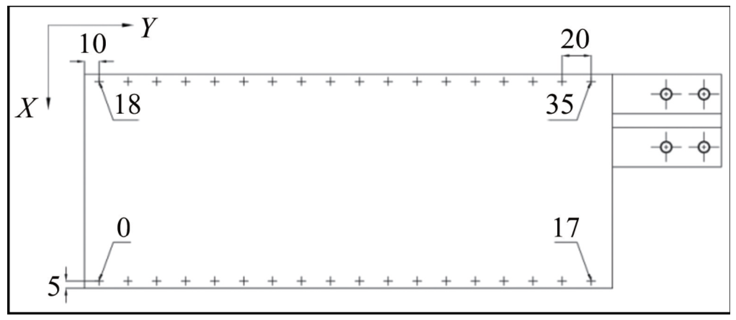
2. Model Definition and Morphing Structures

This study focuses on the supercritical airfoil. In our investigation, the wing span and the chord of the airfoil were 365 mm, and 150 mm, respectively. The block of the model at a 0° angle was about 2 percent. The right-hand rule coordinate was chosen with the x-axis pointing in the flow direction and the y-axis pointing towards the lower wall (as shown in Figure 1). The trailing edge of the model would be deflected in the xz plane.
One cantilever beam of a smart structure based on SMA wire was designed. The SMA wire was fixed on the dentate connectors, which were designed inside the model (Figure 2). The wires were arranged along the model span at intervals of 15 mm, which can reduce installation complexity. The SMA material was titanium nickel alloy wire, and the phase transformation temperatures were MS = 20 °C, MF = 9 °C, AS = 45 °C, and Af = 56 °C, respectively. SMA wire, with a diameter of 1 mm, was heated with an electricity current of 2.5 A, which was supplied by a stable power source, and the corresponding temperature was about 60 °C. A power switch controlled the deflection, and the wires were cooled by flow in the wind tunnel. The SMA wire was pre-stretched with a 5.6% pre-strain before the installation, and a specific pre-load was retained. The cavity on the low surface was filled with glass glue, and the model profile was maintained after the installation of the drive mechanism.
To verify the deformation capacity of flexible joint structures, ground tests were conducted to validate the results. As shown in Figure 3, the airfoil profiles before and after deformation were measured using a coordinate machine. The validation results indicated that, compared with the hinge-type mechanism, the wing profile used in this study achieved a smooth transition before and after structure deformation.

3. Test and Numerical Methods
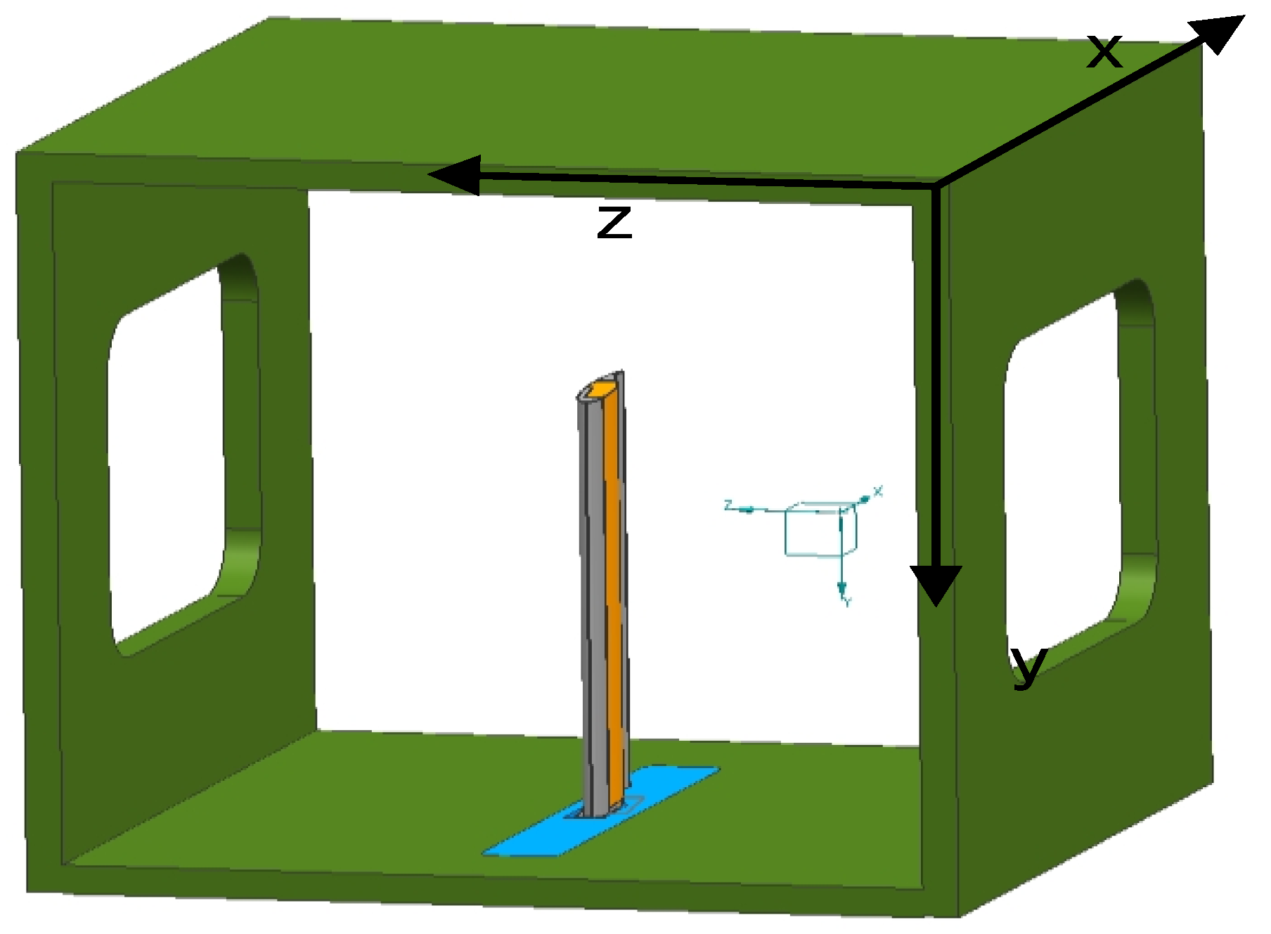
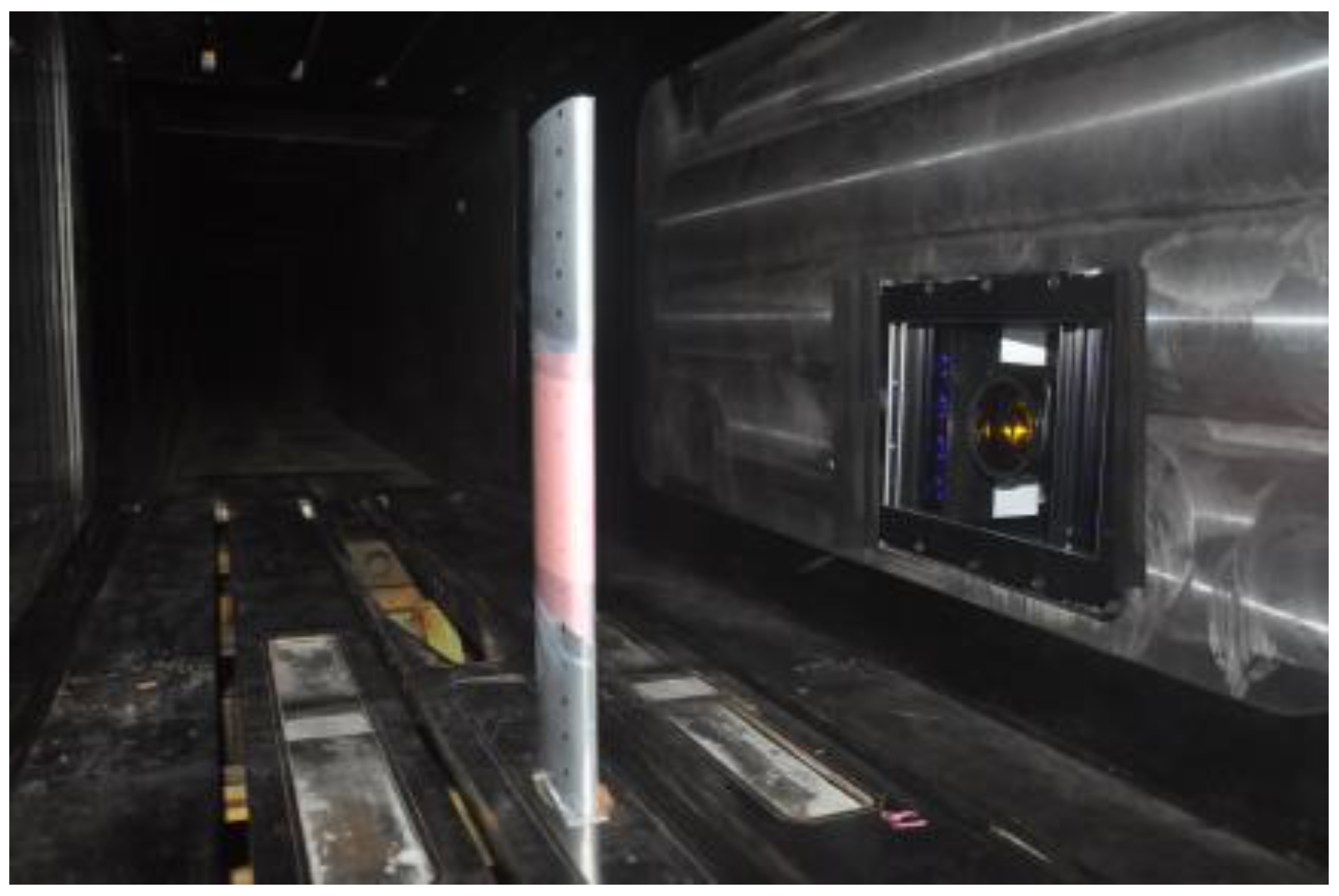
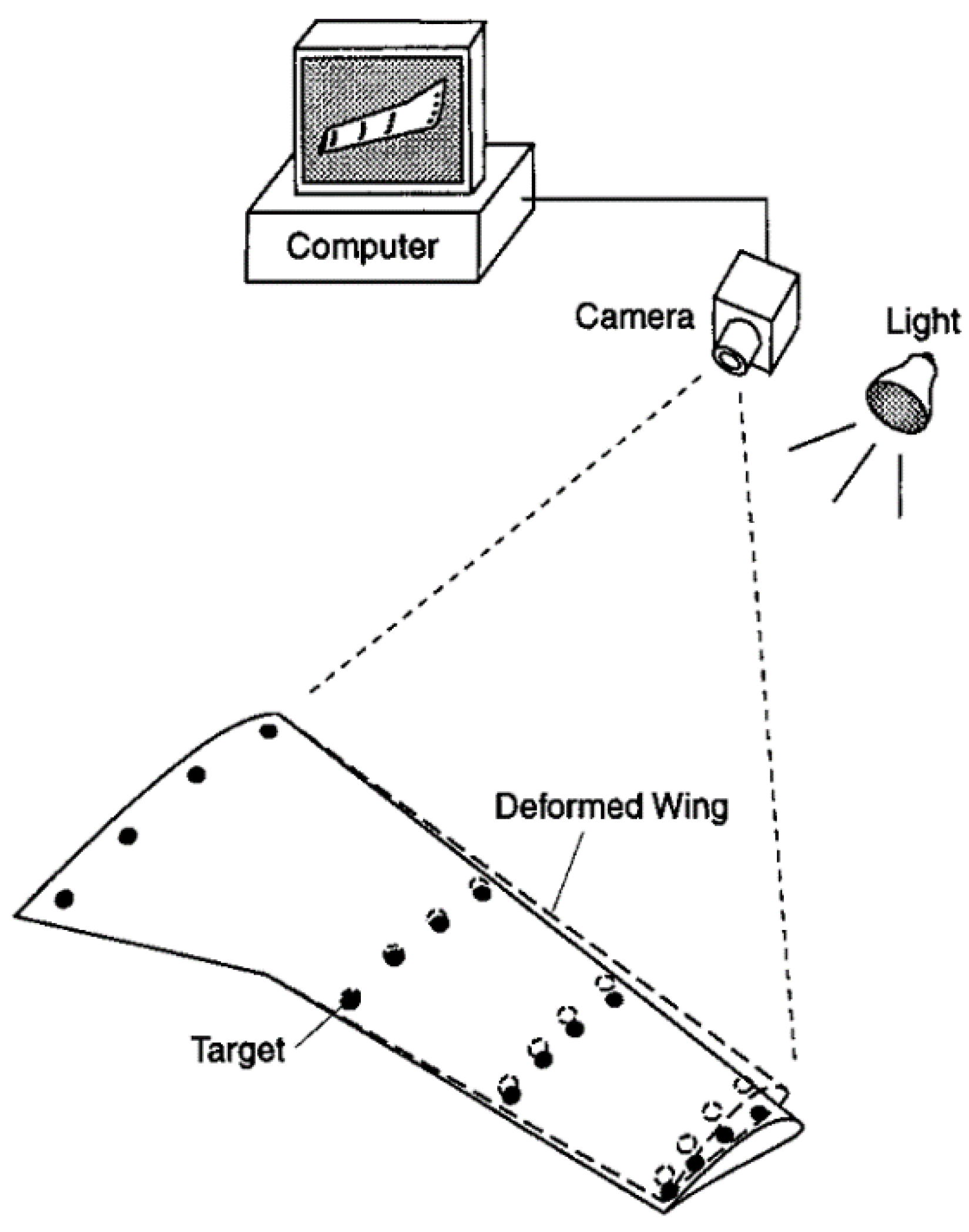
3.1. Facilities

The test was conducted in a transonic wind tunnel with Mach numbers ranging from 0.4 to 3.5. The upper and lower walls of the test section were slotted, and the side walls were solid and equipped with rectangular optical windows for camera recording. The supercritical airfoil model and its relative location in the test section are shown in Figure 4.
Trailing edge deflection was driven by shape memory alloy structures. Pressure distribution was measured by using the pressure scanning valve and the pressure sensitive paint (PSP) technique (only the upper surface pressure distribution). The test Mach numbers ranged from 0.4 to 0.8. Model surface pressure distribution was measured at the attack angles of 0 to 6. The deflection angle of the model trailing edge was measured by using the video motion detector (VMD) system, which comprised an industrial camera, industry computer, light source, and markers. The angle measurement precision of the VMD system was 0.01°. Eighteen groups of markers were located on the upper surface of the model (Figure 5), with a lateral interval of 20 mm and a longitudinal interval of 5 mm.
VMD is an optical measurement method that can determine the spatial coordinate position of the model surface through a series of photos with marked points, thereby determining the target deformation. This technology is particularly suitable for measuring the deformation of wing and control surface models during wind tunnel tests. As shown in Figure 6, the VMD system was composed of an industry camera and lenses, an industrial computer, a light source, and marked points on the model surfaces.
A low-head torsion of the model caused by wind load will affect the theoretical angle of attack of the trailing edge. The corrected angles of attack are −0.5°, 1.5°, 3.4°, and 5.3° (corresponding to theoretical angles of attack of 0°, 2°, 4°, and 6°), with the shape memory alloy temperature as 40 °C.

3.2. Numerical Methods
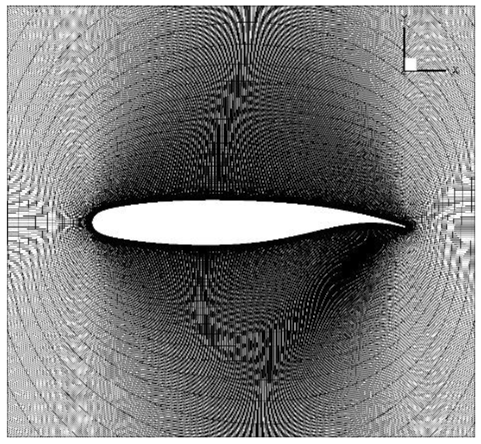
3.2.1. CFD Model

Regardless of the mass force, the conservation form of the Navier–Stokes equation in the Cartesian coordinate system was applied (when α = 0 , the equation was the Euler equation):
Q t + E x + F y + G z = α ( E v x + F v y + G v z ) ,
where:
G = ρ w ρ u w ρ v w ρ w 2 + p ( ρ e t + p ) w ,   F = ρ v ρ v u ρ v 2 + p ρ v w ( ρ e t + p ) v ,   E = ρ u ρ u 2 + p ρ u v ρ u w ( ρ e t + p ) u ,
E v = 0 τ x x τ x y τ x z u τ x x + v τ x y + w τ x z q x ,   F v = 0 τ x y τ y y τ y z u τ x y + v τ y y + w τ y z q y ,   G v = 0 τ x z τ z y τ z z u τ x z + v τ z y + w τ z z q z ,
wherein, the stress items:
τ x x = 2 μ u x 2 3 μ ( u x + v y + w z ) , τ x y = τ y x = μ ( u y + v x ) , τ y y = 2 μ v y 2 3 μ ( u x + v y + w z ) ,
τ z z = 2 μ w z 2 3 μ ( u x + v y + w z ) , τ y z = τ z y = μ ( v z + w y ) , τ x z = τ z x = μ ( u z + w x ) ,
Heat conduction terms:
q y = k T y ;   q x = k T x ;   q z = k T z ,
The total energy per unit mass of gas:
e = p ( g 1 ) r + u 2 + v 2 + w 2 2 ,
Gas state equation: p = ρ R T ; h = c p T .
Viscosity coefficient: computed using the Sutherland formula or Keys formula.
Turbulence model: the S-A viscosity model was applied.
The time term was implicitly discretized, and the dual-time method was adopted. By using the “sub-iteration” technology of the pseudo-time method, the time derivative terms could be decomposed into the second-order precision lower upper-symmetric Gauss–Seidel (LU-SGS) scheme. The viscous term was discretized with the central difference scheme, and the convection term was discretized using a non-oscillating and non-free-parameter dissipative finite difference (NND) scheme.
The inflow conditions of turbulent kinetic energy and turbulent dissipation are as follows:
k = 3 2 ρ T μ 2 ,
v = 10 k / μ l ,
The initial condition is consistent with the incoming flow condition. The walls were a non-slip surface. Turbulent kinetic energy and turbulent dissipation were calculated as follows:
u w a l l = 0 , v w a l l = 0 , w w a l l = 0 k w a l l = 0 , ω w a l l = 60 μ 1 ρ 1 β ( d 1 ) 2 ,
In order to ensure the accuracy of the turbulence calculation, the normal wall should be arranged with sufficiently dense boundary later mesh to meet the requirements y+ < 1.

3.2.2. Structural Motion Calculation

The generalized structural motion equation can be expressed as follows:
M q ¨ t + D q ˙ t + K q t = F t ,
w x , y , z , t = i = 1 N q i t j i x , y , z ,
F t = i = 1 3 D f i x , y , z , t j i x , y , z d s ,
Here, we do not make linear assumptions about the structure, and the generalized mass, damping, and stiffness matrix are related to the structural deformation. Based on finite element calculation software, the structural deformation under the action of multiple forces was computed, and the solid wall boundary conditions (structural displacement) required for flow field calculation were obtained.

3.2.3. Fluid–Structure Interaction Mode

The fluid–structure interaction analysis of deformable bodies was a quasi-steady analysis process. The time history of numerical simulation is not an important issue; therefore, the loose coupling method is widely used in the fluid–structure interaction problem of deformable bodies. Fluid mechanics equations and structural mechanics equations are solved independently, and data exchange only occurs between aerodynamic load and structural displacement during the calculation. This coupling method is similar to parallel research of two independent courses since there is no direct connection between the two courses except for the relevant data exchange; therefore, different models can be replaced separately for comparative research when necessary, which takes up few computer system resources.

3.2.4. Data Exchange between Different Physical Fields

The infinite plate spline (IPS) method and radial basis function (RBF) method are mainly used to transfer data between fluid mechanics and structure mechanics interaction calculations.
The principle of the IPS method is to treat the known data as a plate described by the simulation function wi(xi,yi). The plate satisfies the static equilibrium equation, in which D is the elastic coefficient of the plate and q is the load distribution of the plate. It is assumed that the solution of the equation is as follows:
w ( x , y ) = a 0 + a 1 x + a 2 y + i = 1 N F i r i 2 l n r i 2 ,
where
r i 2 = ( x x i ) 2 + ( y y i ) 2 ,
Taking displacement interpolation as an example, as long as N + 3 unknown parameters in the above equation are determined ( a 0 , a 1 , a 2 , F 1 , F 2 , , F N ) , N equations can be constructed from N data points, and three equations of force and moment balance need to be added:
i = 1 N F i = 0 ,   i = 1 N x i F i = 0 ,   i = 1 N y i F i = 0 ,
Set the parameter vector p = ( a 0 , a 1 , a 2 , F 1 , F 2 , , F N ) T , and
C s s = 0 0 0 1 1 0 0 0 x s 1 x s n s 0 0 0 y s 1 y s n s 1 x s 1 y s 1 r 12 2 l n r 12 2 r 1 n 2 l n r 1 n s 2 1 x s n s y s n s r 1 n s 2 l n r 1 n s 2 r n s n s 2 l n r n s n s 2 ,
A f s = 1 x f 1 y f 1 r f 1 s 1 2 l n r f 1 s 1 2 r f 1 s n s 2 l n r f 1 s n s 2 1 x f 2 y f 2 r f 2 s 1 2 l n r f 2 s 1 2 r f 2 s n s 2 l n r f 2 s n s 2 1 x f n f y f n f r f n f s 1 2 l n r f n f s 1 2 r f n f s n s 2 l n r f n f s n s 2 ,
Then:
u s = C s s p ,
u s = A f s p ,
u f = A f s p = A f s C s s 1 u s ,
The structural displacement interpolation matrix is obtained as follows:
H = A f s C s s 1 ,
which implies
u f = H u s ,
F s = H T F a ,
The coarseness of the mesh will affect the accuracy and efficiency of the calculation. The calculation grid used in this research is shown in Figure 7. The mesh size of the model surface is 1 × 10⁵, and the computation domain size is 1200 (circumferential) × 140 (radial), totalling 168,000 grid nodes.
Figure 8 shows a comparison between the calculated values and literature values under the conditions of Ma = 0.721, Re = 40 × 106, and 0.032° angle of attack. The results of the trailing edge and the lower wing surface match each other well. There are certain differences between the results near the leading edge and the shock wave region. It should be noted that this set of grids is suitable for Reynolds numbers above one million, and the wall grid y+ is in the range of 0.7~1.1. However, the experimental Reynolds number in the literature is above ten million, which leads to a larger wall grid y+ ranging from 7 to 14. Therefore, the difference between the results is understandable. The results showed that the grid quality was good enough to meet the requirements of this research.

4. Results

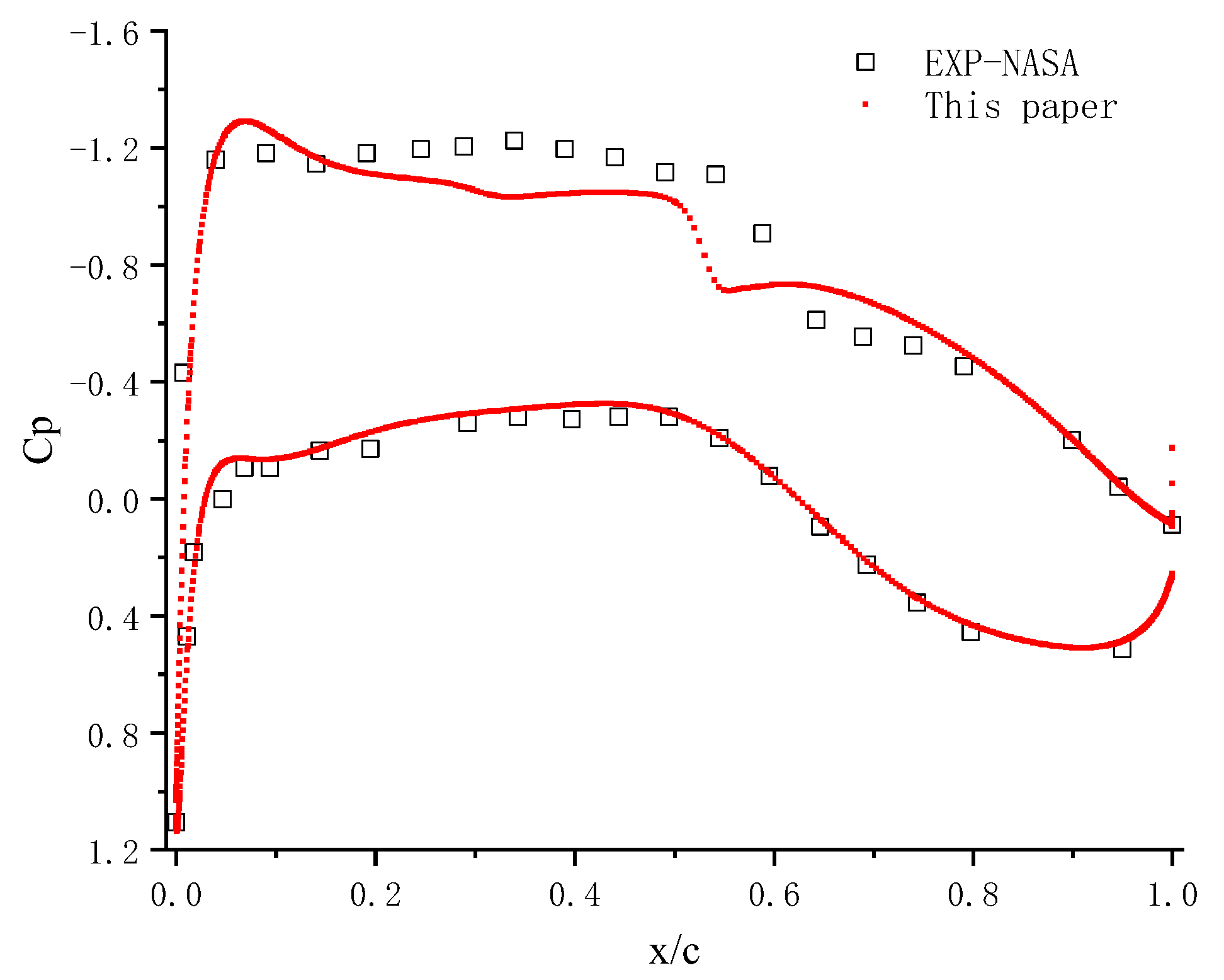
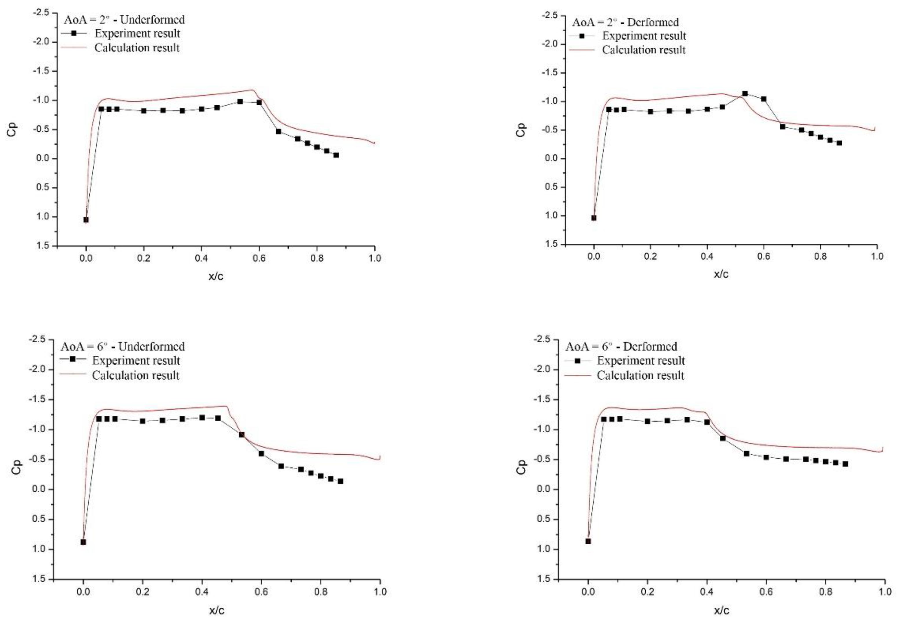
4.1. Comparison of CFD Results with Test Results

Unless otherwise specified, the following experiments were conducted at a Mach number of 0.8. Since this work did not focus on the influence of Mach numbers, no other Mach number experiments were conducted. As shown in Figure 9, CFD could simulate the pressure distribution and shock wave position at the airfoil’s leading edge and whether the airfoil’s trailing edge was deflected. In general, the numerical simulation could correctly show the pressure distribution changes. However, compared with CFD results, due to the influence of PSP, the kinetic energy decreased in the experiments, resulting in relatively lower flow acceleration and a lower pressure peak.

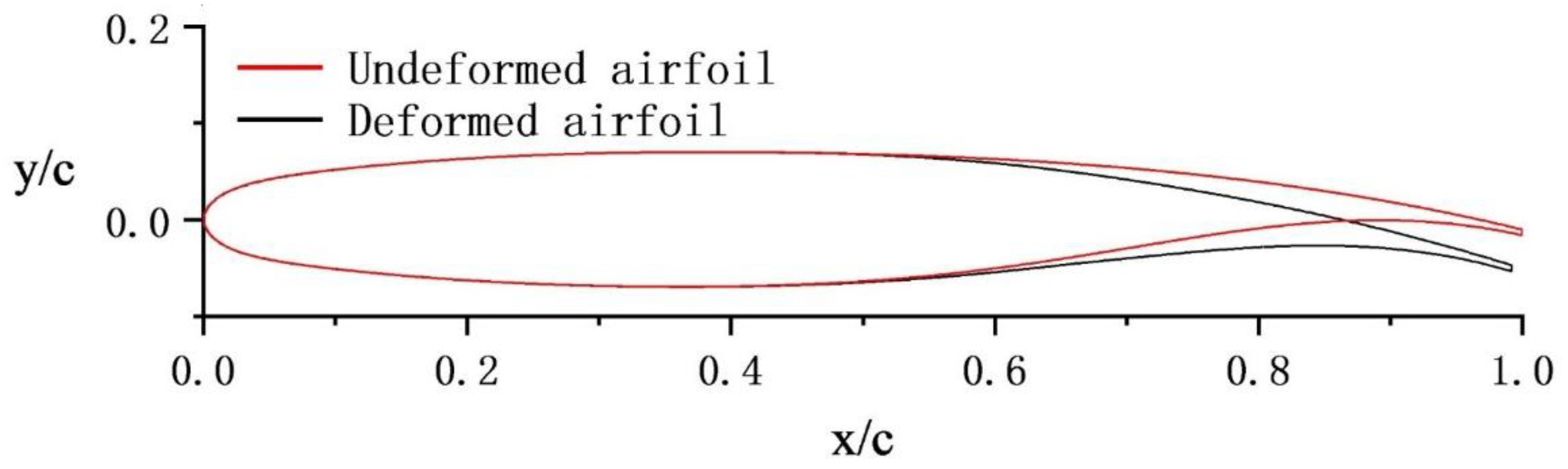
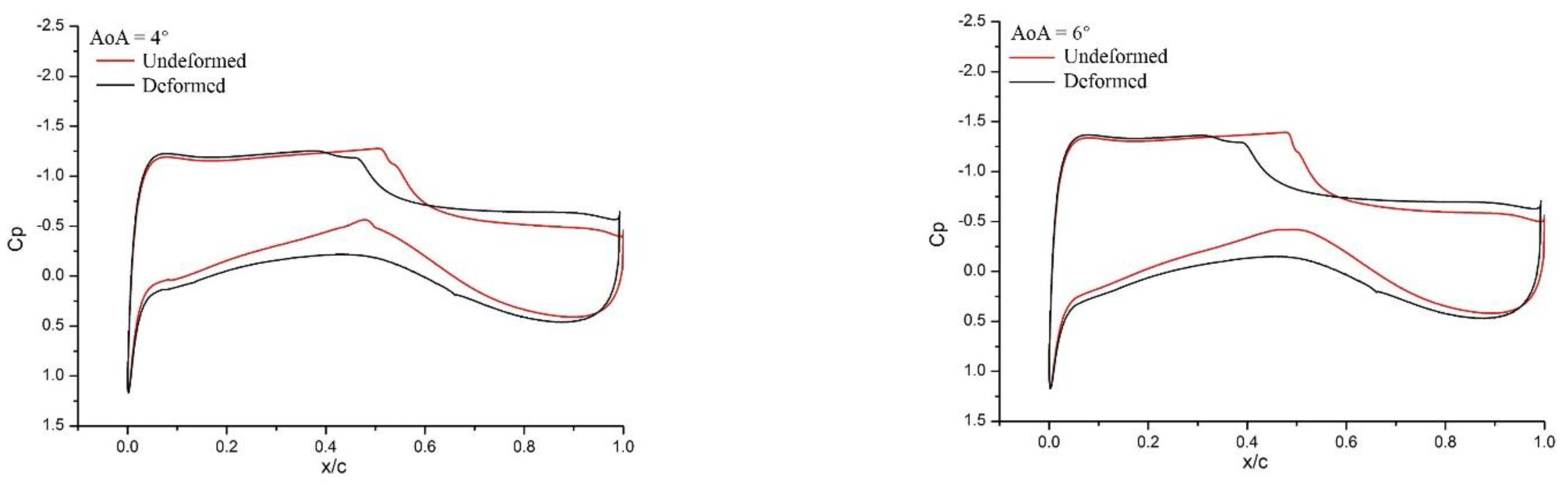
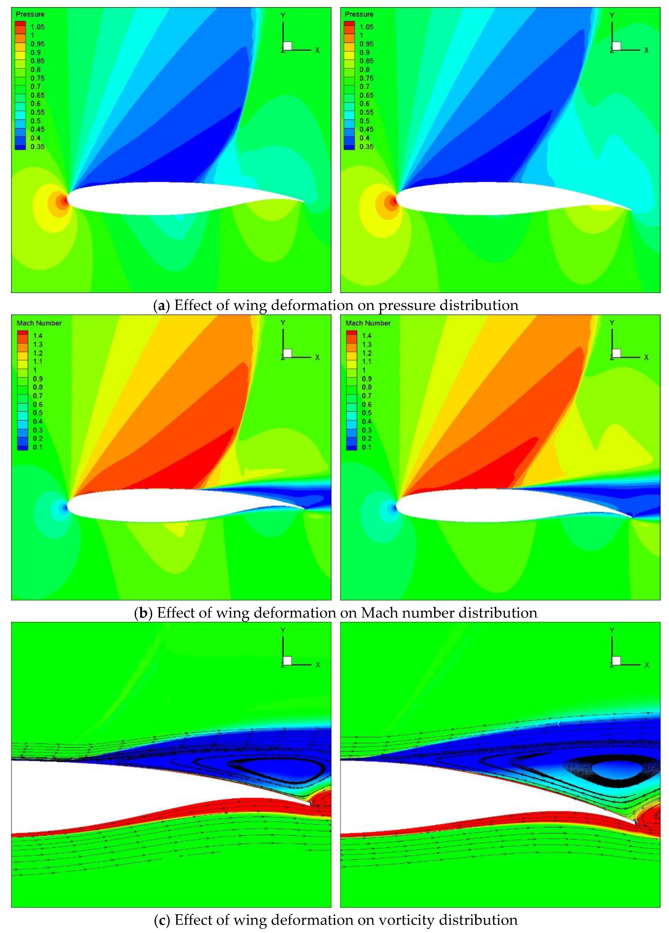
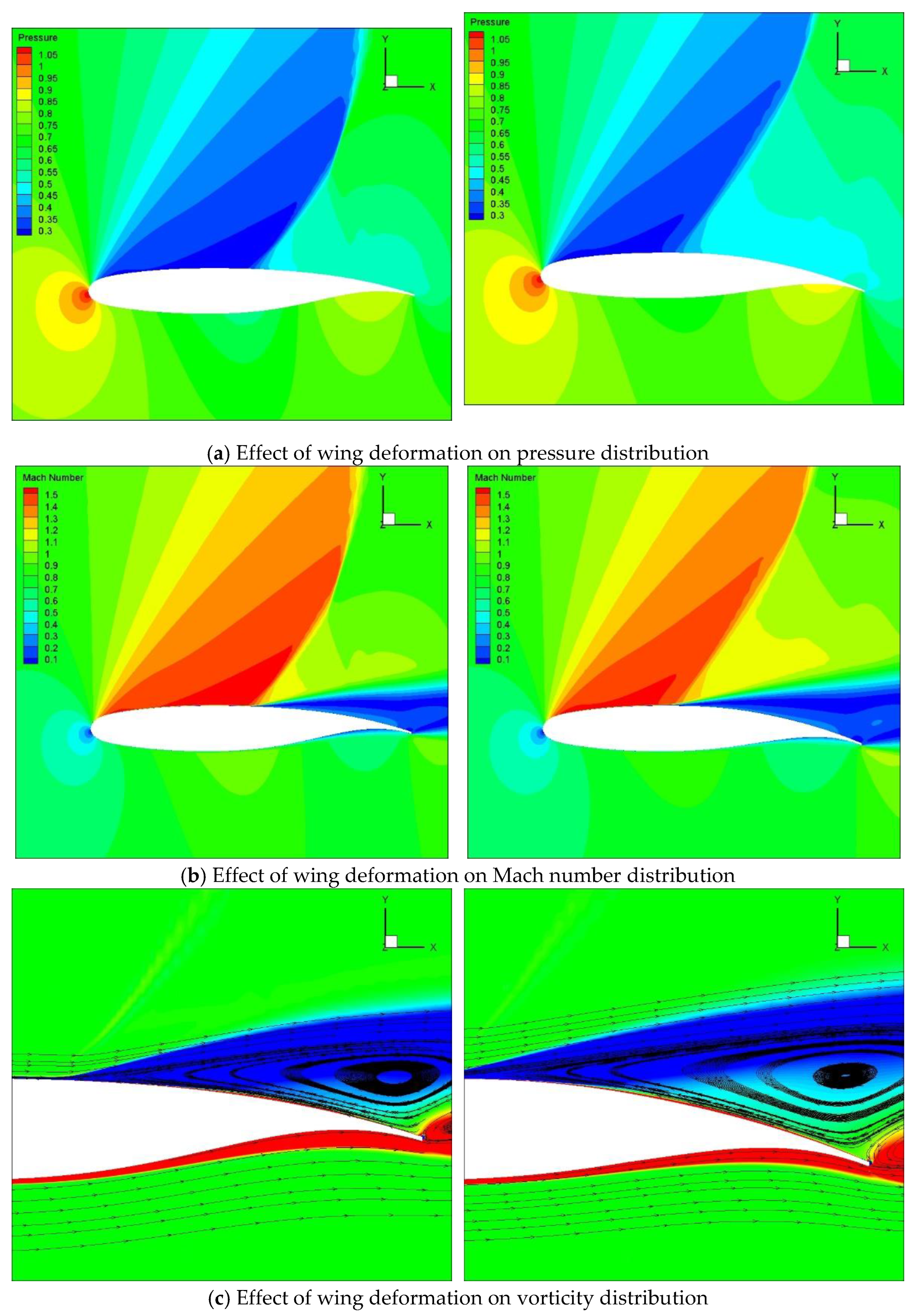
4.2. Effect of Wing Deformation on Flow Structure

In Figure 10, the effect of wing deformation on vorticity distribution can be seen.
In Figure 11 and Figure 12, the shock wave position on the upper wing moves forward, and the pressure recovery on the trailing edge becomes worse when the trailing edge is deflected. As can be seen from the streamlines in the vorticity distribution, the dominant range of the separated vortex induced by the shock wave was enlarged after the trailing edge was deflected, which was equivalent to an increase in the airfoil thickness and the drag of the airfoil. The results also showed that the trailing edge deformation weakened the flow velocity or the shock wave (lower angles of attack) strength of the lower surface, which made the pressure distribution smoother and the lift coefficient of the entire airfoil higher. The trailing edge deflection caused the shock wave position to move forward, thereby causing the flow separation point induced by the shock wave to move forward, expanding the flow separation area, and increasing the pressure drag coefficient of the airfoil. On the other hand, due to the fact that the pressure coefficients on the airfoil surface within the separation zone were basically the same, the expansion of the separation zone increased the lift on the trailing edge of the airfoil, thereby increasing the lift coefficient of the airfoil.

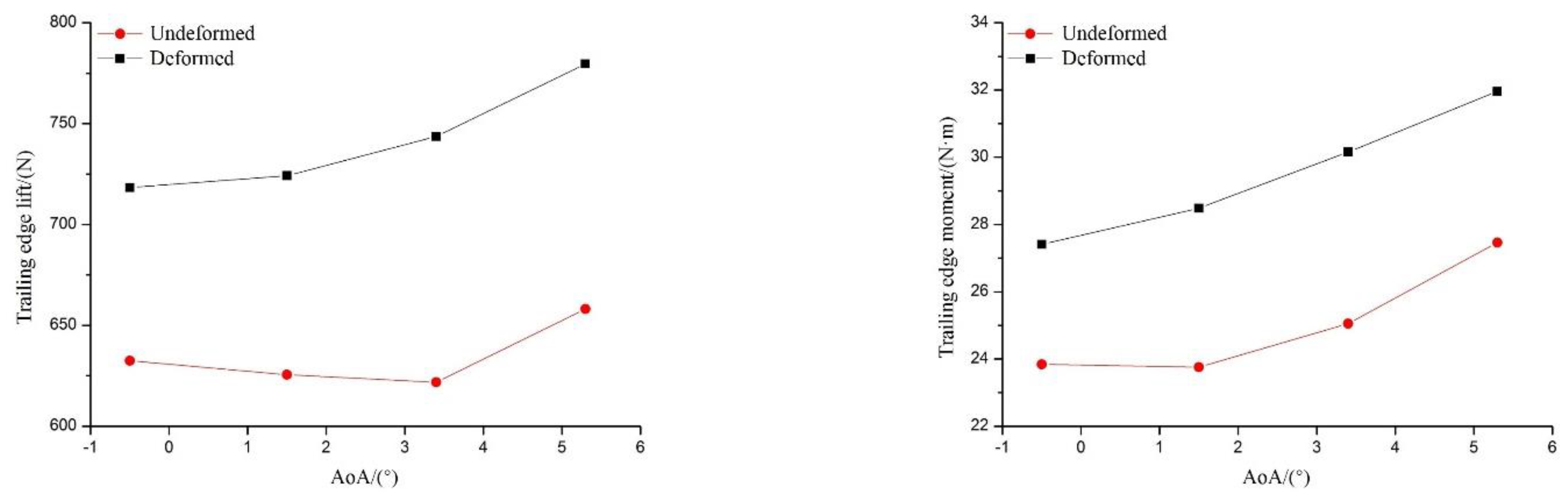
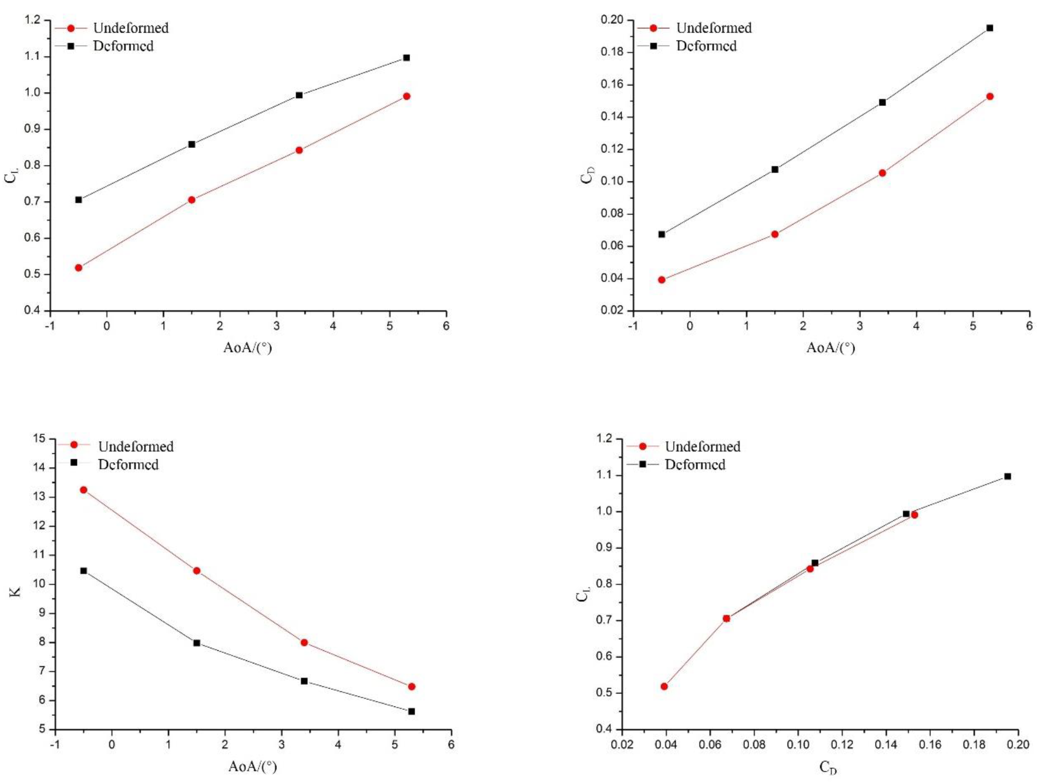
4.3. Deformation’s Impact on Aerodynamic Characteristics

The effect of deformation on trailing edge lift and pitch moment relative to the flexible joint is shown in Figure 13. The results showed that the trailing edge deformation significantly increased the lift and moment of the model trailing. The higher the angle of attack, the more pronounced the increment of the trailing edge lift, which made it more difficult for the trailing edge to be deformed.
Figure 14 shows the effect of deformation on the lift/drag coefficient, lift/drag ratio, and the polar curve. As can be seen, the lift coefficient of the airfoil increases after the trailing edge deformation, while its increment decreases with the angle of attack increasing. The drag coefficient was also increased after the trailing edge deformation, which resulted in a decrease in the lift/drag ratio. In other words, the aerodynamic characteristics of the morphing airfoil here were not improved. The polar curves of the deformed airfoil and undeformed airfoil basically coincided, indicating that under the same lift coefficient, the drag and lift/drag ratio of the deformed airfoil and undeformed airfoil were the same. The deformation provided a control moment for the airfoil while maintaining the same lift/drag ratio.

5. Conclusions

The effect of airfoil morphing on the flow field and aerodynamic coefficients were ascertained by using the existing fluid–structure interaction calculation method. The following conclusions are drawn:
(1) The results obtained using CFD and wind tunnel testing were consistent with each other and well under the condition of M = 0.8. The trailing edge deformation made the shock wave position move forward along the airfoil’s upper surface, and the suction peak decreased;
(2) The downward deflection of the airfoil trailing edge made the flow velocity of the lower wing change more smoothly, and the lift increased;
(3) The lift and drag coefficients of the deformed airfoil were increased, while the lift/drag ratio was slightly reduced.
In summary, this paper provides a reference for the design of camber morphing wings and gives guiding data for the fluid–structure interaction mechanism of trailing edge deformation. Although this work contributes to the reliability and safety of cambered morphing wings’ design, there are still some issues that need to be solved in the future. Tools such as particle image velocimetry can be used to visualize the flow field, and Mach numbers’ influence can be determined in further research.

Author Contributions

Conceptualization, Y.W. and B.L.; software, Y.W.; validation, P.L., Y.L. and H.G.; formal analysis, Y.L.; investigation, Y.W. and B.L.; resources, Y.W. and B.L.; data curation, B.L.; writing—original draft preparation, Y.W.; writing—review and editing, P.L., B.L., Y.L. and H.G.; supervision, B.L. All authors have read and agreed to the published version of the manuscript.

Funding

This research received no external funding.

Data Availability Statement

The data for this work are available from the corresponding author upon reasonable request.

Conflicts of Interest

The authors declare no conflict of interest.

Nomenclature

c p Isobaric specific heat
ρIncoming flow density
uIncoming flow velocity
TIncoming flow turbulence
μlLaminar viscosity coefficient of the incoming flow
ρ1, d1Density of the first layer of the grid center near the object surface and the distance to the model surface
w x , y , z , t Structural deformation vector of the model surface
F t , q t Generalized displacement and the generalized aerodynamic force, respectively
M , D , K Generalized mass, damping, and stiffness matrices of the structure
F t Generalized aerodynamics, which link the structure with aerodynamics
Fs, FaStructural point force vector and aerodynamic force vector, respectively

References

  1. Wlezien, R.W.; Horner, G.C.; McGowan, A.-M.R.; Padula, S.L.; Scott, M.A.; Silcox, R.J.; Harrison, J.S. Aircraft morphing program. In Smart Structures and Materials 1998: Industrial and Commercial Applications of Smart Structures Technologies; SPIE: Bellingham, WA, USA, 1998; pp. 176–187. [Google Scholar]
  2. Bashir, M.; Longtin-Martel, S.; Botez, R.M.; Wong, T. Aerodynamic design optimization of a morphing leading edge and trailing edge airfoil–application on the uas-s45. Appl. Sci. 2021, 11, 1664. [Google Scholar] [CrossRef]
  3. Ozbek, E.; Ekici, S.; Karakoc, T.H. Unleashing the Potential of Morphing Wings: A Novel Cost Effective Morphing Method for UAV Surfaces, Rear Spar Articulated Wing Camber. Drones 2023, 7, 379. [Google Scholar] [CrossRef]
  4. Bye, D.; Mcclure, P. Design of a morphing vehicle. In Proceedings of the 48th AIAA/ASME/ASCE/AHS/ASC Structures, Structural Dynamics, and Materials Conference, Honolulu, HI, USA, 23–26 April 2007; p. 1728. [Google Scholar]
  5. Le Sant, Y.; Mignosi, A.; Deléglise, B.; Bourguignon, G. Model deformation measurement (MDM) at Onera. In Proceedings of the 25th AIAA Applied Aerodynamics Conference, Miami, FL, USA, 25–28 June 2007; p. 3817. [Google Scholar]
  6. Kudva, J.N. Overview of the DARPA smart wing project. J. Intell. Mater. Syst. Struct. 2004, 15, 261–267. [Google Scholar] [CrossRef]
  7. Ivanco, T.; Scott, R.; Love, M.; Zink, S.; Weisshaar, T. Validation of the Lockheed Martin morphing concept with wind tunnel testing. In Proceedings of the 48th AIAA/ASME/ASCE/AHS/ASC Structures, Structural Dynamics, and Materials Conference, Honolulu, HI, USA, 23–26 April 2007; p. 2235. [Google Scholar]
  8. Flanagan, J.; Strutzenberg, R.; Myers, R.; Rodrian, J. Development and flight testing of a morphing aircraft, the NextGen MFX-1. In Proceedings of the 48th AIAA/ASME/ASCE/AHS/ASC Structures, Structural Dynamics, and Materials Conference, Honolulu, HI, USA, 23–26 April 2007; p. 1707. [Google Scholar]
  9. Ruyten, W.; Sellers, M. Demonstration of optical wing deformation measurements at the Arnold engineering development center. In Proceedings of the 47th AIAA Aerospace Sciences Meeting including the New Horizons Forum and Aerospace Exposition, Orlando, FL, USA, 5–8 January 2009; p. 1520. [Google Scholar]
  10. Bowman, J.; Sanders, B.; Cannon, B.; Kudva, J.; Joshi, S.; Weisshaar, T. Development of next generation morphing aircraft structures. In Proceedings of the 48th AIAA/ASME/ASCE/AHS/ASC Structures, Structural Dynamics, and Materials Conference, Honolulu, HI, USA, 23–26 April 2007; p. 1730. [Google Scholar]
  11. Skvarenina, T.L. The Power Electronics Handbook; CRC Press: Boca Raton, FL, USA, 2018. [Google Scholar]
  12. Burner, A.; Liu, T. Videogrammetric model deformation measurement technique. J. Aircr. 2001, 38, 745–754. [Google Scholar] [CrossRef]
  13. Zhao, Z.; Ren, X.; Gao, C.; Xiong, J.; Liu, F.; Luo, S. Experimental study of shock wave oscillation on SC (2)-0714 airfoil. In Proceedings of the 51st AIAA Aerospace Sciences Meeting including the New Horizons Forum and Aerospace Exposition, Grapevine, TX, USA, 7–10 January 2013; p. 537. [Google Scholar]
  14. Kancharla, A.K.; Roy Mahapatra, D. Aerodynamic pressure variation over SMA wire integrated morphing aerofoil. In Proceedings of the 49th AIAA/ASME/ASCE/AHS/ASC Structures, Structural Dynamics, and Materials Conference, 16th AIAA/ASME/AHS Adaptive Structures Conference, 10th AIAA Non-Deterministic Approaches Conference, 9th AIAA Gossamer Spacecraft Forum, 4th AIAA Multidisciplinary Design Optimization Specialists Conference, Schaumburg, IL, USA, 7–10 April 2008; p. 2044. [Google Scholar]
  15. Lv, B.; Wang, Y.; Lei, P. Effects of trailing edge deflections driven by shape memory alloy actuators on the transonic aerodynamic characteristics of a super critical airfoil. Actuators 2021, 10, 160. [Google Scholar] [CrossRef]
  16. Brailovski, V.; Terriault, P.; Georges, T.; Coutu, D. SMA actuators for morphing wings. Phys. Procedia 2010, 10, 197–203. [Google Scholar] [CrossRef]
  17. Cevdet, Ö.; Özbek, E.; Ekici, S. A review on applications and effects of morphing wing technology on uavs. Int. J. Aviat. Sci. Technol. 2021, 1, 30–40. [Google Scholar]
  18. Mohd Jani, J.; Leary, M.; Subic, A. Designing shape memory alloy linear actuators: A review. J. Intell. Mater. Syst. Struct. 2017, 28, 1699–1718. [Google Scholar] [CrossRef]
  19. Wang, Y.; Lv, B.; Lei, P.; Shi, W.; Yan, Y. Study on Flow Mechanism of a Morphing Supercritical Airfoil. Shock. Vib. 2021, 2021, 5588056. [Google Scholar] [CrossRef]
  20. Tang, W.; Sandström, R. Limitations of constitutive relations for TiNi shape memory alloys. J. Phys. IV 1995, 5, C8-185–C188-190. [Google Scholar] [CrossRef]
  21. Spillman, W., Jr.; Sirkis, J.; Gardiner, P. Smart materials and structures: What are they? Smart Mater. Struct. 1996, 5, 247. [Google Scholar] [CrossRef]
  22. Wada, K.; Liu, Y. Some factors affecting the shape recovery properties of NiTi SMA. In Proceedings of the 47th AIAA/ASME/ASCE/AHS/ASC Structures, Structural Dynamics, and Materials Conference 14th AIAA/ASME/AHS Adaptive Structures Conference 7th, Newport, RI, USA, 1–4 May 2006; p. 1969. [Google Scholar]
  23. Li, W.; Xiong, K.; Chen, H.; Zhang, X.; Su, Y.; Ren, Z. Research on variable cant angle winglets with shape memory alloy spring actuators. Acta Aeronaut. Et Astronaut. Sin. 2012, 33, 22–33. [Google Scholar]
  24. Jenkins, R.V. Aerodynamic Performance and Pressure Distributions for a NASA SC (2)-0714 Airfoil Tested in the Langley 0.3-Meter Transonic Cryogenic Tunnel; National Aeronautics and Space Administration, Scientific and Technical: Washington, DC, USA, 1988; Volume 4044. [Google Scholar]
  25. Chong, K.P.; Garboczi, E.J. Smart and designer structural material systems. Prog. Struct. Eng. Mater. 2002, 4, 417–430. [Google Scholar] [CrossRef]
  26. Jenkins, R.V. NASA SC (2)-0714 Airfoil Data Corrected for Sidewall Boundary-Layer Effects in the Langley 0.3-Meter Transonic Cryogenic Tunnel; NASA, Scientific and Technical Information Division: Washington, DC, USA, 1989; Volume 2890. [Google Scholar]
  27. Grigorie, T.L.; Botez, R.M. A Self–Tuning Intelligent Controller for a Smart Actuation Mechanism of a Morphing Wing Based on Shape Memory Alloys. Actuators 2023, 12, 350. [Google Scholar] [CrossRef]
  28. Precup, N.; Mor, M.; Livne, E. The design, construction, and tests of a concept aeroelastic wind tunnel model of a high-lift variable camber continuous trailing edge flap (HL-VCCTEF) wing configuration. In Proceedings of the 56th AIAA/ASCE/AHS/ASC Structures, Structural Dynamics, and Materials Conference, Kissimmee, FL, USA, 5–9 January 2015; p. 1406. [Google Scholar]
  29. Icardi, U.; Ferrero, L. Preliminary study of an adaptive wing with shape memory alloy torsion actuators. Mater. Des. 2009, 30, 4200–4210. [Google Scholar] [CrossRef]
  30. Livne, E.; Precup, N.; Mor, M. Design, construction, and tests of an aeroelastic wind tunnel model of a variable camber continuous trailing edge flap (VCCTEF) concept wing. In Proceedings of the 32nd AIAA Applied Aerodynamics Conference, Atlanta, GA, USA, 16–20 June 2014; p. 2442. [Google Scholar]
Figure 1. Model coordinates.
Vibration 06 00062 g001
Figure 2. Morphing structures based on SMA.
Vibration 06 00062 g002
Figure 3. Coordinate machine measurement results.
Vibration 06 00062 g003
Figure 4. Model in the test section.
Vibration 06 00062 g004
Figure 5. Markers on the model surface.
Vibration 06 00062 g005
Figure 6. VMD system.
Vibration 06 00062 g006
Figure 7. Partial view of calculation grid.
Vibration 06 00062 g007
Figure 8. Comparison of airfoil calculation results and experimental results.
Vibration 06 00062 g008
Figure 9. Comparison between CFD and test results.
Vibration 06 00062 g009
Figure 10. Effect of deformation on pressure distribution.
Vibration 06 00062 g010
Figure 11. Effect of deformation on aerodynamics characteristics (α = 4°).
Vibration 06 00062 g011
Figure 12. Effect of deformation on aerodynamic characteristics (α = 6°).
Vibration 06 00062 g012
Figure 13. Effect of deformation on lift and moment of trailing edge.
Vibration 06 00062 g013
Figure 14. Effect of airfoils’ morphing on aerodynamic coefficients.
Vibration 06 00062 g014
Disclaimer/Publisher’s Note: The statements, opinions and data contained in all publications are solely those of the individual author(s) and contributor(s) and not of MDPI and/or the editor(s). MDPI and/or the editor(s) disclaim responsibility for any injury to people or property resulting from any ideas, methods, instructions or products referred to in the content.

