
A Review on Vibration-Based Damage Detection Methods for Civil Structures

Abstract
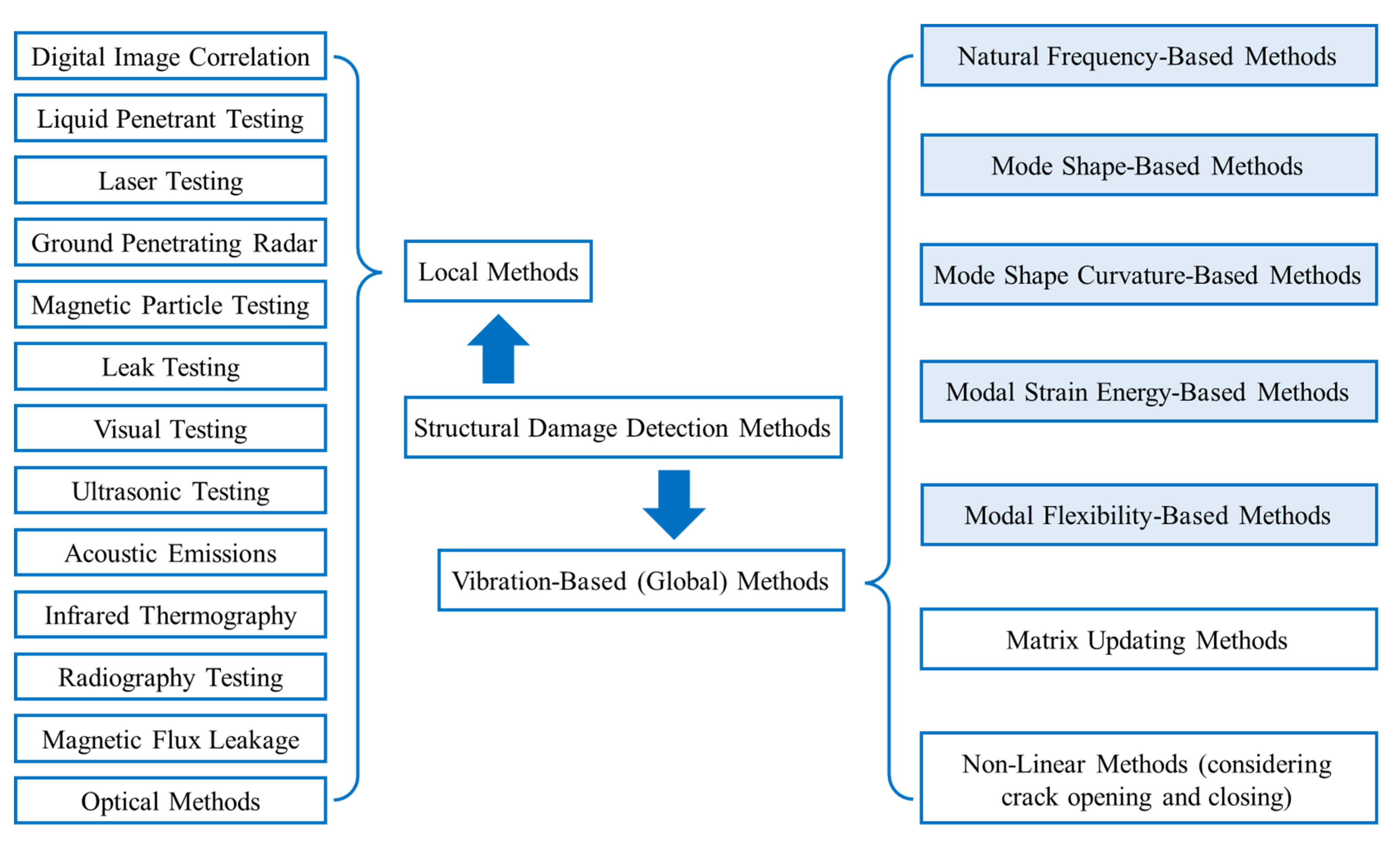
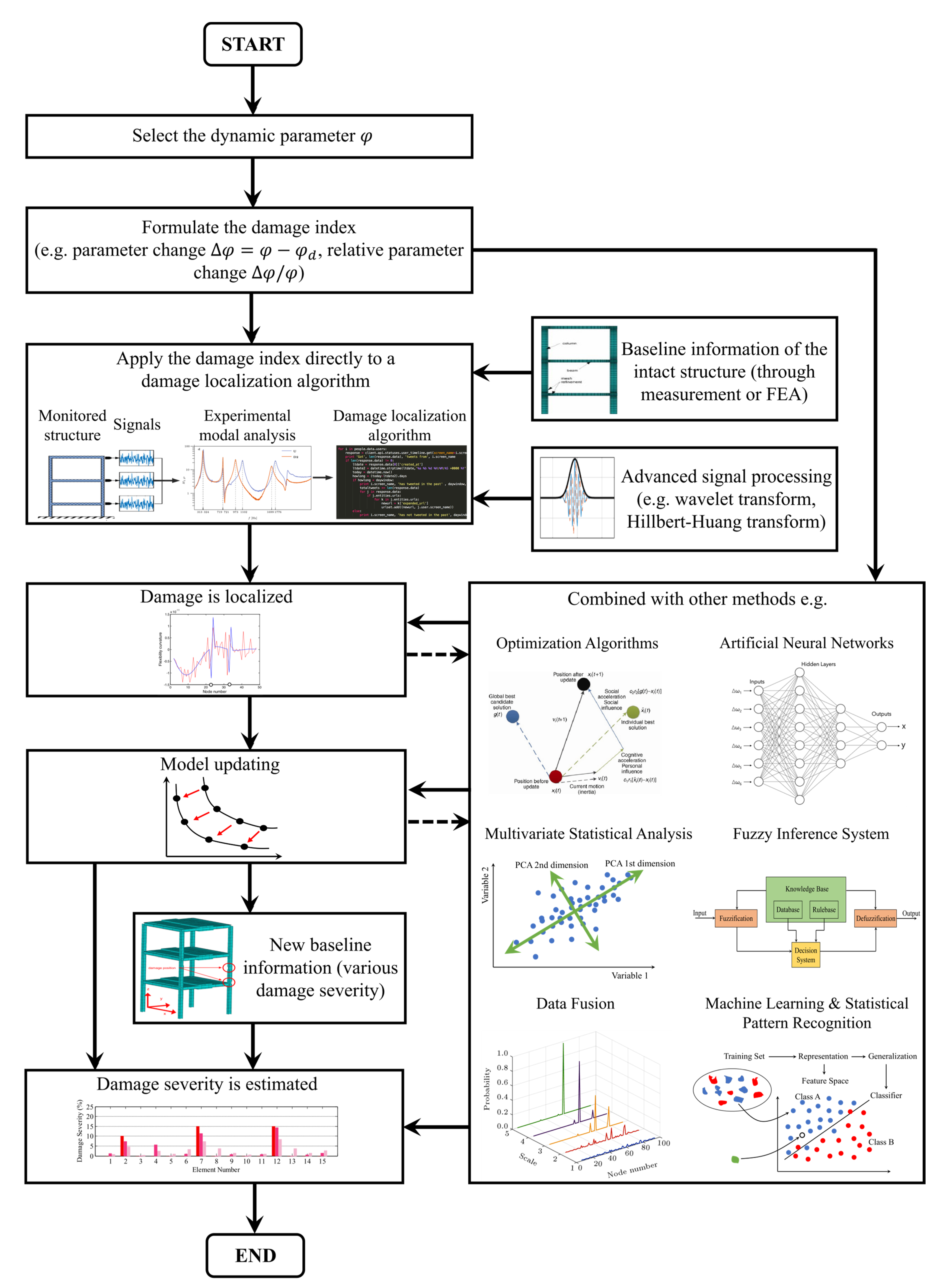
:1. Introduction
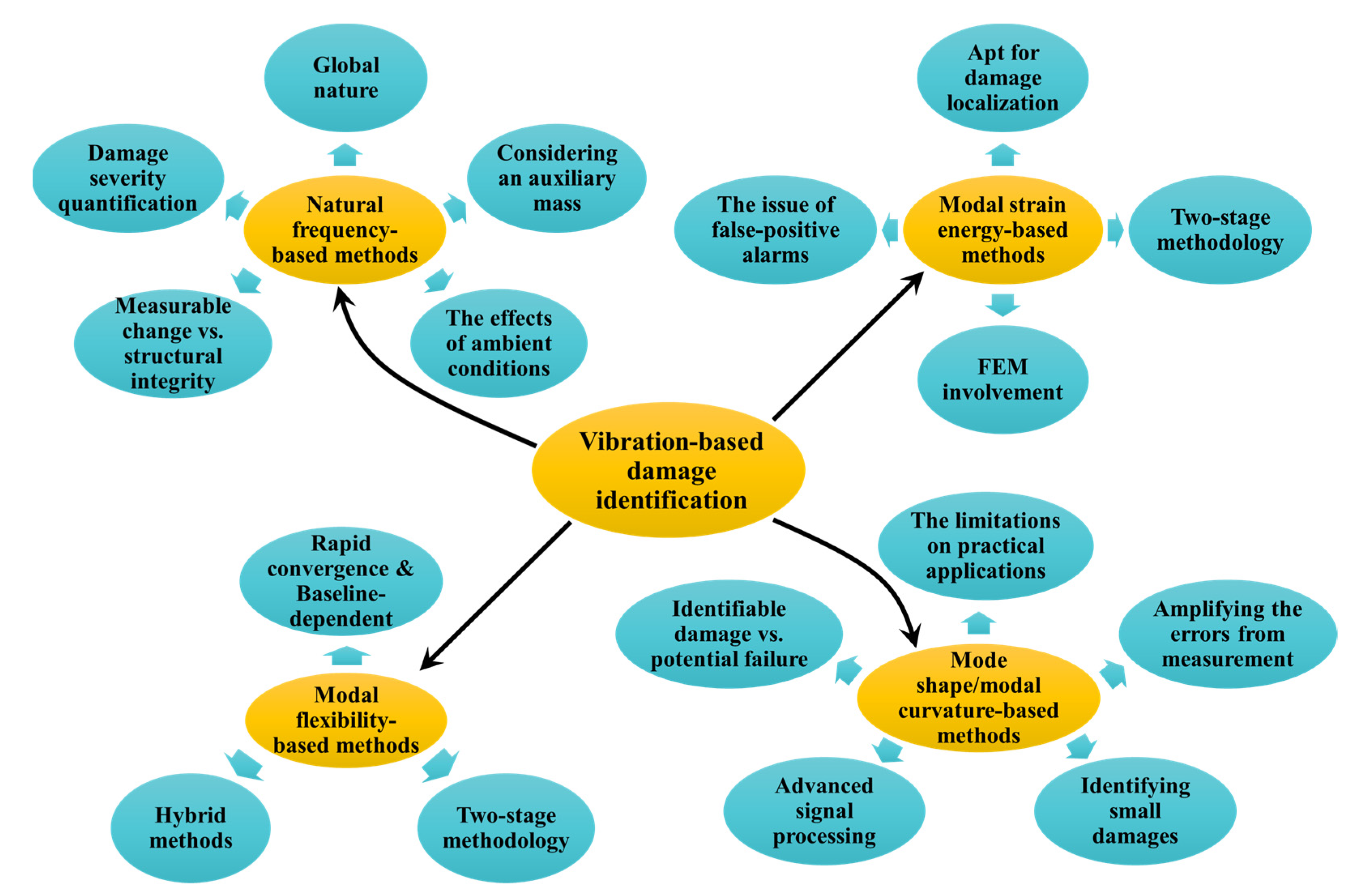
2. Methods Based on Natural Frequency
2.1. Review
2.2. Comments
- (1)
- An advantage of the natural frequency-based approach is the global nature of natural frequency. It is a good indicator of the overall mass and stiffness of a structure. This characteristic, on the other hand, may render the natural frequency weakly sensitive to minor damage because minor damage tends to be a local phenomenon. Methods incorporating signal processing techniques, e.g., wavelet transform, are proposed to deal with this weak sensitivity [30,32]; however, new challenges, such as how to optimize the sampling interval [31], require further research.
- (2)
- A combination of different damages may lead to identical frequency changes [51]. For unique identification of damage location, there are a few promising ways to include the spatial information of damage in frequency responses. For example, an auxiliary mass with or without rotary inertia can be attached to the structure [20,21,22,23,24,30,32,33,34]. In this case, the mass acts as a probe, and the spatial information of damage is contained in the curve of frequency versus mass location. This helps to separate the location effect from the severity effect.
- (3)
- To date, most natural frequency-based damage detection methods are verified by successfully detecting cracks of moderate size (e.g., with dimensionless crack depth between 0.2 and 0.5 for skeletal structures) as the resulting frequency changes are easier to capture. Taking the frequency change as input data, the feasibility of the crack detection method can be tested. Nevertheless, a question that remains unaddressed is the direct comparison between the crack severity reaching the initiation of crack propagation or leading to brittle fracture and the crack severity causing a measurable frequency change. If the former severity is reached before the latter, frequency-based crack detection would be risky. If, on the other hand, the crack already causes measurable frequency drops in the first few modes before it jeopardizes the safety of a structure, then there may be some safety margin where frequency-based crack detection can be executed. Overall, with this issue being unsolved, even when cracks of moderate size are detected successfully in a controlled experimental condition, it is debatable whether the presented crack detection method is feasible in practical situations. To make a direct comparison, fracture toughness in fracture mechanics would be an important parameter to determine the critical state of crack propagation or brittle fracture.
- (4)
- The damage-induced frequency changes may be veiled by the frequency changes due to other factors such as the effects of ambient conditions (e.g., temperature, humidity, wind, rainfall, etc.), operating loads, and possible evolution of boundary conditions. It has been reported in [25,26,27,28] that the frequency variation due to such environmental and operational factors is usually of the order of 5–10% but can exceed this. Currently, most successful frequency-based damage detection methods are verified only under controlled laboratory conditions rather than exposed to variations in environmental or operational effects. In practical applications, damage-induced frequency changes should, as a minimum, be expected to exceed 5% to detect the damage with confidence.
- (5)
- Quantifying the damage severity is still a challenging task, and to date, there are few simple and robust methods. The method comparing the frequency response of damaged structures with ‘baseline information’ that contains different damage scenarios exhibits its viability in numerical simulations and laboratory environments. However, a large amount of calculation, either through the finite element analysis or in an analytical manner, is necessary to obtain the ‘baseline information,’ which may render this method impractical when using it in complex structures. One possible way to reduce the computation is to roughly estimate the damage location ranges, then accurately localize the damage and quantify the severity. For example, the method in [41] can be used to preliminarily narrow down the ranges where the crack may be located, and then other methods based on pattern recognition or global optimization can be employed to search for the optimal solution (i.e., the damage location) within the prescribed spans. Once the damage location is found, the severity of the damage can be evaluated in the second step by trial and error to find the severity that gives results matching experimental measurements.
3. Methods Based on Mode Shapes and Their Derivatives
3.1. Review of Mode Shape-Based Damage Detection Methods
3.2. Review of Modal Curvature-Based Damage Detection Methods
3.3. Comments
- (1)
- As natural frequencies represent the global dynamic characteristics of a structure, in general, their measurement alone may not be sufficient to draw spatial information on the damage. Measurement of mode shapes and their derivatives may be more useful. However, mode shape-based methods tend to be very sensitive to measurement inaccuracy, which may obscure damage-induced perturbations. Moreover, a large number of measurement points are required to estimate a detailed mode shape or a high-order mode shape when using MAC and other relevant assurance criteria in damage detection, which inevitably increases the duration of the measurement. The accessibility of measurement points could also pose problems. These factors place limitations on the practical application of the mode shape-based method.
- (2)
- Since mode shape is not sensitive enough to minor damage, many damage indices defined by modal curvature have been proposed in the literature. Modal curvature is commonly computed by numerical differentiation, which amplifies the errors in measurements. This is particularly worse when modal curvature is obtained from a densely-measured mode shape. To address these problems, generally, four approaches are employed, namely, reducing noise [64,66,67], filtering or smoothing [59,60,71], reducing measurement points [59,61], and measuring modal curvature directly [74,75]. For damage detection using modal curvature only, three ways are known to alleviate noise effects, i.e., optimal sampling interval [31,61], signal processing [66,80,81], and multi-resolution analysis [65,68]. Nevertheless, the opinion held by several researchers that reducing noise cannot essentially solve the problem caused by the inherent flaw of the numerical difference [71] is valid as the causes of deviations are entirely independent. Similarly, reducing measurement points (down-sampling) is not always a reasonable choice as it may increase the lower bound of the detectable damage severity, which impairs the identification of minor damage.
- (3)
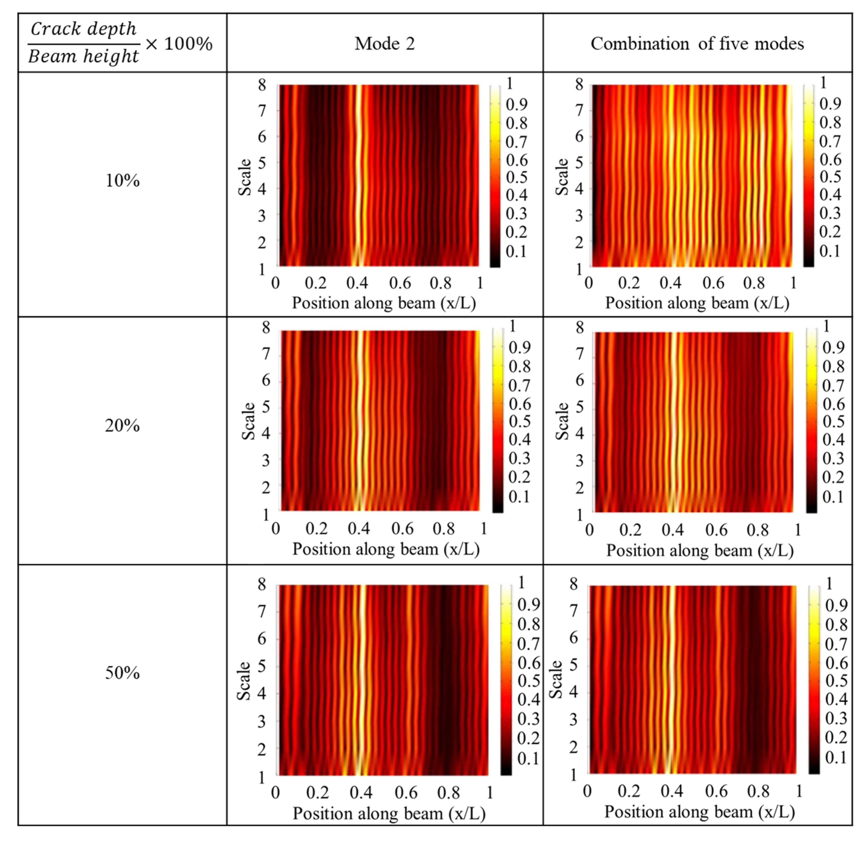
- Combining the wavelet transform and modal curvature helps to focus on damage effects, and small damage in a plate can be identified in the laboratory environment using a scanning laser vibrometer [79,80,82,83]. This is more advantageous compared with natural frequency-based methods. In addition, there is no specific requirement for the shape of damage. The damage can be through-thickness damage or a thickness reduction. The depth of the damage can be constant or non-uniform [80]. However, the minimum detectable damage can be directly affected by noise, and the damage near boundaries cannot be identified owing to the boundary distortion issue when using wavelet transform signal processing.
- (4)
- When wavelet signal processing is applied, one way to avoid boundary distortion and identify the boundary damage simultaneously is to use baseline information. For example, some damage indices are proposed based on mode shape difference [81] and the curvature difference of operational deformation shapes [84]. By using these indices, the effect of a sudden change in stiffness near boundaries is canceled; hence, boundary distortion is circumvented. Nevertheless, this is achieved at the sacrifice of an advantage of wavelet signal processing, i.e., baseline information free. The benefit is that, normally, high-order mode shapes are not essential when baseline information is available. This is in sharp contrast to the situation where baseline information is unavailable. In those situations, the necessary order of mode shape may exceed ten to ensure the successful identification of small damages [69,79,82].
4. Methods Based on Modal Strain Energy
4.1. Review
4.2. Comments
- (1)
- In most modal strain energy-based methods, modal strain energy is checked element by element. The advantage is that damage can be localized within an element (if disregarding false alarms), and the accuracy can be guaranteed (if the element size is reasonable). The disadvantage is that the number of elements increases for complex structures, and more degrees of freedom are involved. Modal strain energy in multiple degrees of freedom should be considered to ensure that no false-negative alarms occur. Therefore, most studies are focusing on beams, planar frames, and 3D frames. For 3D frames, the modal strain energy decomposition method is necessary.
- (2)
- The performance of modal strain energy-based methods in damage quantification is generally unsatisfactory. Optimization algorithms or FE model updating are often utilized to estimate damage severity. Thus, many modal strain energy-based damage detection methods exhibit a two-stage feature, i.e., damage location is determined in the first stage, and damage severity is evaluated in the second stage. This is a common characteristic of many vibration-based damage detection methods, but it is more obvious when modal strain energy is used. A false-positive alarm in the first stage may lead to error in the second stage, and a false-negative alarm in the first stage cannot be corrected afterward. Thus, the iterative two-stage method (e.g., [92]), where the two stages are conducted alternately, deserves further research.
- (3)
- As modal strain energy is evaluated in an elementwise manner, modal strain energy-based methods fit the finite element method (FEM) well. In many numerical studies using the FEM, the damage is considered by introducing elemental stiffness reduction. Although many damage indices are proven reliable in numerical studies, simulated and experimental results may differ significantly. This is because cracks or corrosion in practical applications may not exactly map to the general stiffness degradation of an element. Apart from numerical studies, more experimental studies are needed to assess and, if possible, improve the reliability of modal strain energy-based methods for practical applications.
- (4)
- The presence of the false-positive alarm remains a major challenge. Normally, it is assumed that the effect of damage is constrained within a certain element and other elements are intact. However, the actual effect of damage usually distributes unevenly in a certain area instead of being concentrated. Thus, false-positive alarms could happen near the damage. Wei et al. [88] presented a method for reducing false-positive alarms, but at the cost that the magnitude of the damage index was holistically suppressed. It means the number of false-negative alarms may increase if the damage is minor and the signal contains noise. Overall, the problem of false alarms calls for further research.
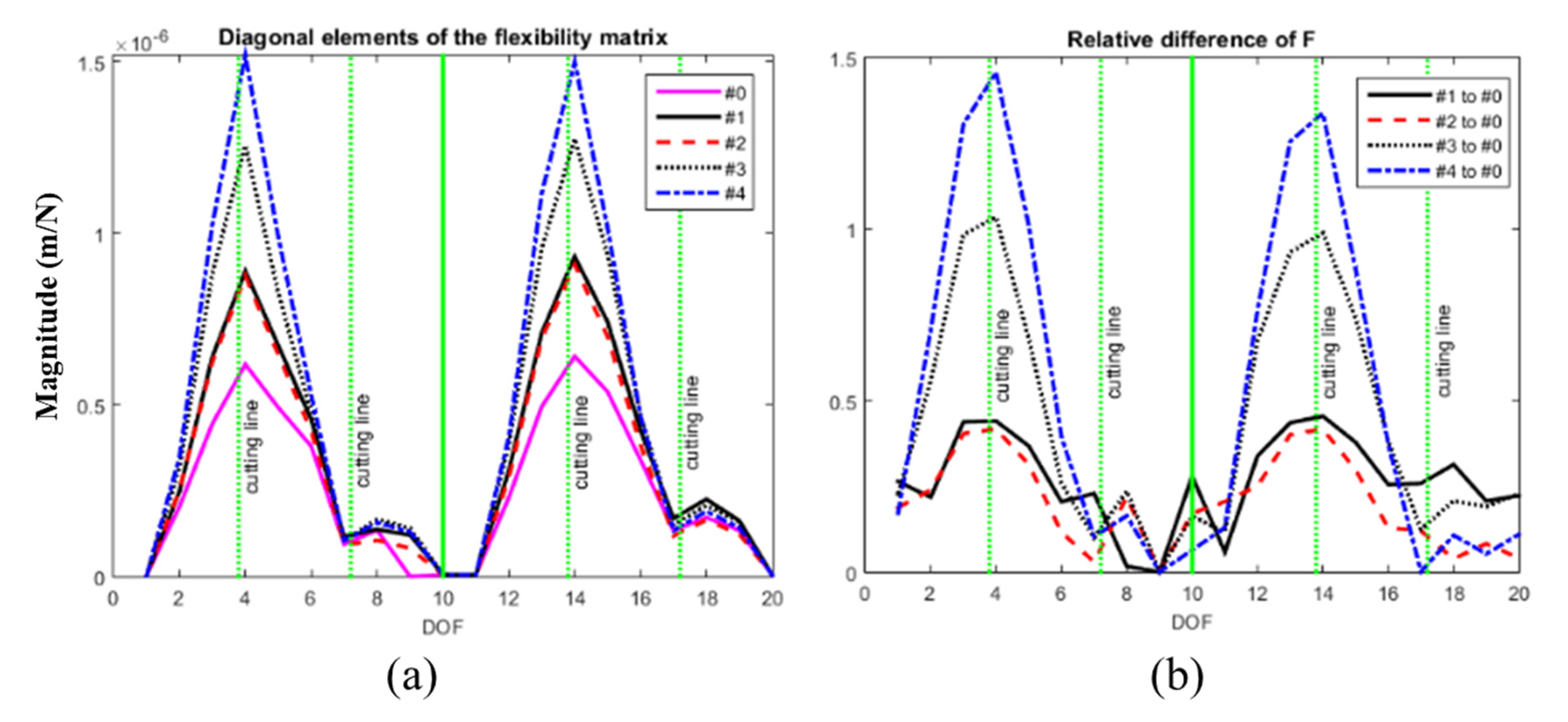
5. Methods Based on Modal Flexibility
5.1. Review
5.2. Comments
- (1)
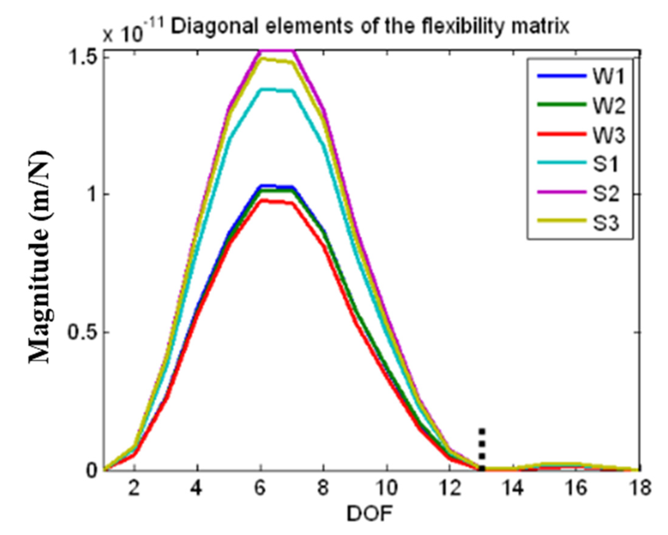
- The greatest strength of the modal flexibility-based damage index is that modal flexibility converges rapidly with increasing natural frequency. Thus, the modal flexibility matrix can be properly estimated by using the first few modes. This is beneficial because, normally, only a limited number of modes can be measured in a practical structure. However, most of the damage indices are based on modal flexibility change, which means baseline information is indispensable. This is the most obvious limitation of modal flexibility-based methods. Baseline information is obtained from the FE model of the intact structure in many studies, whereas baseline information is not always available for a practical structure.
- (2)
- Modal flexibility is a function of both natural frequencies and mode shapes. It inherits the noise immunity of natural frequency as well as the spatial information from mode shape, which makes it a sensitive parameter to damage location. However, it is difficult to formulate an explicit relationship between modal flexibility and damage severity. Thus, the modal flexibility-based damage index is not a good candidate for severity estimation.
- (3)
- Data-driven techniques (e.g., data fusion, clustering, big data analytics, etc.) seem promising when dealing with some challenging situations where, for example, multiple damages are present or modal data contain considerable noise. Although multi-damage scenarios are considered in the above literature, it is still unknown whether the proposed methods are applicable for identifying closely spaced damages. Moreover, when there are multiple damages with distinct severity, the performance of those methods seems not satisfactory. It is shown in [112] that compared with using the relative change of modal flexibility alone, multiple damages can be identified more clearly when data fusion is employed. For the heavily noise-polluted modal data, ref. [113] shows that the clustering approach has stable performance. Overall, hybrid methods combining data-driven techniques or statistical pattern recognition deserve further research.
6. Concluding Remarks and Future Recommendations
- (1)
- Damage-induced changes in dynamic parameters such as natural frequency, mode shape, modal curvature, etc., have been used as indices in damage detection. However, the changes in parameters relevant to structural integrity, such as levels of stress and displacement, have been ignored. For example, damage-induced changes in stress fields have not been fully utilized in vibration-based damage detection. When the damage severity varies, natural frequency, displacement, and stress levels may change to different extents. This then raises a question of whether the damage that causes a small change in natural frequency, which is difficult to distinguish from measurement noise based on existing technologies, can cause stress levels that are significant enough to warrant remedial action. If this is not the case, then frequency measurement based on current technology can still be a good indicator of damage that should trigger inspection and repair. Thus, a direct comparison between the crack severity threatening structural integrity and the crack severity causing a measurable frequency change is necessary.
- (2)
- An auxiliary system affiliating to a damaged beam and plate has been used for damage detection. For example, a stationary roving mass is utilized to enhance the effect of a crack on the dynamics of a cracked beam and provide additional spatial information about the crack [19,30]. A roving mass with or without rotary inertia has been used for crack detection in beams, plates, and cylindrical shells [20,21,33,34] without any knowledge of the theoretical model and irrespective of the crack severity. However, its practical application is yet to be explored. Firstly, further research is required to determine whether the measured frequency change is higher than the change caused by measurement noise in practical situations. Secondly, the fact that the rotary inertia does not act at a point would make the theoretical frequency jump in [33,34] simply a steep change, which will raise the difficulty to discern the frequency change, and advanced signal processing techniques such as wavelet transform may be needed. A potential application of this method may be the use of traffic or a dedicated vehicle to test the integrity of a bridge or monitor the health of a bridge. This would also mean further research is needed to consider not only the effect of a roving body but also the effect of a moving body, in which factors such as the velocity of the vehicle need to be considered.
Author Contributions
Funding
Conflicts of Interest
References
- Hellier, C. Handbook of Nondestructive Evaluation, 2nd ed.; McGraw Hill Professional: New York, NY, USA, 2013. [Google Scholar]
- Avci, O.; Abdeljaber, O.; Kiranyaz, S.; Hussein, M.; Gabbouj, M.; Inman, D.J. A review of vibration-based damage detection in civil structures: From traditional methods to Machine Learning and Deep Learning applications. Mech. Syst. Signal Proc. 2021, 147, 107077. [Google Scholar] [CrossRef]
- Wang, Z.; Ong, K. Autoregressive coefficients based Hotelling’s T2 control chart for structural health monitoring. Comput. Struct. 2008, 86, 1918–1935. [Google Scholar] [CrossRef]
- Teughels, A.; Maeck, J.; De Roeck, G. Damage assessment by FE model updating using damage functions. Comput. Struct. 2002, 80, 1869–1879. [Google Scholar] [CrossRef]
- Rytter, A. Vibrational Based Inspection of Civil Engineering Structures. Ph.D. Thesis, Department of Building Technology and Structural Engineering, Aalborg University, Aalborg, Denmark, 1993. [Google Scholar]
- Caddemi, S.; Calio, I.; Cannizzaro, F.; Morassi, A. A procedure for the identification of multiple cracks on beams and frames by static measurements. Struct. Control Health Monit. 2018, 25, e2194. [Google Scholar] [CrossRef]
- Buda, G.; Caddemi, S. Identification of concentrated damages in Euler-Bernoulli beams under static loads. J. Eng. Mech. 2007, 133, 942–956. [Google Scholar] [CrossRef]
- Waldmann-Diederich, D.; Erdenebat, D. Potential of the Deformation Area Difference (DAD)-Method for Condition Assessment of Bridge Structures. In Proceedings of the SMAR 2019—5th International Conference on Smart Monitoring, Assessment and Rehabilitation of Civil Structures, Potsdam, Germany, 27–29 August 2019. [Google Scholar]
- Doebling, S.W.; Farrar, C.R.; Prime, M.B. A summary review of vibration-based damage identification methods. Shock Vib. Dig. 1998, 30, 91–105. [Google Scholar] [CrossRef]
- Sekhar, A.S. Multiple cracks effects and identification. Mech. Syst. Signal Proc. 2008, 22, 845–878. [Google Scholar] [CrossRef]
- Sinou, J.J. A review of damage detection and health monitoring of mechanical systems from changes in the measurement of linear and non-linear vibrations. In Mechanical Vibrations: Measurement, Effects and Control; Sapri, R.C., Ed.; Nova Science Publishers, Inc.: New York, NY, USA, 2009; pp. 643–702. [Google Scholar]
- Fan, W.; Qiao, P. Vibration-based damage identification methods: A review and comparative study. Struct. Health Monit. 2011, 10, 83–111. [Google Scholar] [CrossRef]
- Katunin, A. Nondestructive damage assessment of composite structures based on wavelet analysis of modal curvatures: State-of-the-art review and description of wavelet-based damage assessment benchmark. Shock Vib. 2015, 2015, 735219. [Google Scholar] [CrossRef]
- Worden, K.; Dulieu-Barton, J.M. An Overview of Intelligent Fault Detection in Systems and Structures. Struct. Health Monit. 2016, 3, 85–98. [Google Scholar] [CrossRef]
- Bovsunovsky, A.; Surace, C. Non-linearities in the vibrations of elastic structures with a closing crack: A state of the art review. Mech. Syst. Signal Proc. 2015, 62–63, 129–148. [Google Scholar] [CrossRef]
- Giannini, O.; Casini, P.; Vestroni, F. Nonlinear harmonic identification of breathing cracks in beams. Comput. Struct. 2013, 129, 166–177. [Google Scholar] [CrossRef]
- Caddemi, S.; Caliò, I.; Marletta, M. The dynamic non-linear behaviour of beams with closing cracks. In Proceedings of the AIMETA 2009 XIX Congresso di Meccanica Teorica ed Applicata, Ancona, Italy, 14–17 September 2009. [Google Scholar]
- Kisa, M.; Brandon, J. The effects of closure of cracks on the dynamics of a cracked cantilever beam. J. Sound Vibr. 2000, 238, 1–18. [Google Scholar] [CrossRef]
- Zhong, S.; Oyadiji, S.O. Analytical predictions of natural frequencies of cracked simply supported beams with a stationary roving mass. J. Sound Vibr. 2008, 311, 328–352. [Google Scholar] [CrossRef]
- Zhang, Y.; Wang, L.; Lie, S.T.; Xiang, Z. Damage detection in plates structures based on frequency shift surface curvature. J. Sound Vibr. 2013, 332, 6665–6684. [Google Scholar] [CrossRef]
- Zhang, Y.; Lie, S.T.; Xiang, Z.; Lu, Q. A frequency shift curve based damage detection method for cylindrical shell structures. J. Sound Vibr. 2014, 333, 1671–1683. [Google Scholar] [CrossRef]
- Lie, S.; Zhang, Y.; Wang, L. Damage detection in compressed natural gas (CNG) cylinders based on auxiliary mass induced frequency shift. Exp. Mech. 2015, 55, 487–498. [Google Scholar] [CrossRef]
- Cao, L.; He, W.-Y.; Ren, W.-X. Damage localization and quantification for beam bridges based on frequency variation of parked vehicle-bridge systems. Structures 2021, 31, 357–368. [Google Scholar] [CrossRef]
- Wang, L.; Zhang, Y.; Lie, S.T. Detection of damaged supports under railway track based on frequency shift. J. Sound Vibr. 2017, 392, 142–153. [Google Scholar] [CrossRef]
- Liu, C.; DeWolf, J.T. Effect of temperature on modal variability of a curved concrete bridge under ambient loads. J. Struct. Eng. 2007, 133, 1742–1751. [Google Scholar] [CrossRef]
- Xia, Y.; Hao, H.; Zanardo, G.; Deeks, A. Long term vibration monitoring of an RC slab: Temperature and humidity effect. Eng. Struct. 2006, 28, 441–452. [Google Scholar] [CrossRef]
- Sohn, H. Effects of environmental and operational variability on structural health monitoring. Philos. Trans. A Math. Phys. Eng. Sci. 2007, 365, 539–560. [Google Scholar] [CrossRef]
- Peeters, B.; De Roeck, G. One-year monitoring of the Z24-Bridge: Environmental effects versus damage events. Earthq. Eng. Struct. Dyn. 2001, 30, 149–171. [Google Scholar] [CrossRef]
- Schommer, S.; Mahowald, J.; Nguyen, V.H.; Waldmann, D.; Maas, S.; Zürbes, A.; De Roeck, G. Health monitoring based on dynamic flexibility matrix: Theoretical models versus in-situ tests. Engineering 2017, 9, 37–67. [Google Scholar] [CrossRef]
- Zhong, S.; Oyadiji, S.O. Identification of cracks in beams with auxiliary mass spatial probing by stationary wavelet transform. J. Vib. Acoust. 2008, 130, 041001. [Google Scholar] [CrossRef]
- Sazonov, E.; Klinkhachorn, P. Optimal spatial sampling interval for damage detection by curvature or strain energy mode shapes. J. Sound Vibr. 2005, 285, 783–801. [Google Scholar] [CrossRef]
- Yang, C.; Oyadiji, S.O. Damage detection using modal frequency curve and squared residual wavelet coefficients-based damage indicator. Mech. Syst. Signal Proc. 2017, 83, 385–405. [Google Scholar] [CrossRef]
- Cannizzaro, F.; De Los Rios, J.; Caddemi, S.; Caliò, I.; Ilanko, S. On the use of a roving body with rotary inertia to locate cracks in beams. J. Sound Vibr. 2018, 425, 275–300. [Google Scholar] [CrossRef]
- Ilanko, S.; Mochida, Y.; De Los Rois, J. Vibration Analysis of Cracked Structures as a Roving Body Passes a Crack Using the Rayleigh-Ritz Method. EPI Int. J. Eng. 2018, 1, 30–34. [Google Scholar] [CrossRef]
- Behera, S.; Parhi, D.; Das, H. Numerical, experimental and fuzzy logic applications for investigation of crack location and crack depth estimation in a free-free aluminum beam. Vib. Phys. Syst. 2018, 29, 2018019. [Google Scholar]
- Agarwalla, D.K.; Khan, A.S.; Sahoo, S.K. Application of Genetic Fuzzy System for Damage Identification in Cantilever Beam Structure. Procedia Eng. 2016, 144, 215–225. [Google Scholar] [CrossRef]
- Gomes, G.F.; Mendéz, Y.A.D.; da Cunha, S.S.; Ancelotti, A.C. A numerical–experimental study for structural damage detection in CFRP plates using remote vibration measurements. J. Civ. Struct. Health Monit. 2018, 8, 33–47. [Google Scholar] [CrossRef]
- Sahu, S.; Kumar, P.B.; Parhi, D.R. Intelligent hybrid fuzzy logic system for damage detection of beam-like structural elements. J. Theor. Appl. Mech. 2017, 55, 509–521. [Google Scholar] [CrossRef]
- Zhang, Z.; He, M.; Liu, A.; Singh, H.K.; Ramakrishnan, K.R.; Hui, D.; Shankar, K.; Morozov, E.V. Vibration-based assessment of delaminations in FRP composite plates. Compos. Part B Eng. 2018, 144, 254–266. [Google Scholar] [CrossRef]
- Oliver, G.A.; Ancelotti, A.C.; Gomes, G.F. Neural network-based damage identification in composite laminated plates using frequency shifts. Neural Comput. Appl. 2021, 33, 3183–3194. [Google Scholar] [CrossRef]
- Dahak, M.; Touat, N.; Benseddiq, N. On the classification of normalized natural frequencies for damage detection in cantilever beam. J. Sound Vibr. 2017, 402, 70–84. [Google Scholar] [CrossRef]
- De Los Rios, J.; Ilanko, S.; Kennedy, D. Decoupling severity and location from cracked beams. In Proceedings of the 23rd International Congress on Sound and Vibration, Athens, Greece, 10–14 July 2016. [Google Scholar]
- Labib, A.; Kennedy, D.; Featherston, C.A. Crack localisation in frames using natural frequency degradations. Comput. Struct. 2015, 157, 51–59. [Google Scholar] [CrossRef]
- Greco, A.; Pau, A. Damage identification in Euler frames. Comput. Struct. 2012, 92–93, 328–336. [Google Scholar] [CrossRef]
- Yang, J.; Huang, L.; Tong, K.; Tang, Q.; Li, H.; Cai, H.; Xin, J. A Review on Damage Monitoring and Identification Methods for Arch Bridges. Buildings 2023, 13, 1975. [Google Scholar] [CrossRef]
- Caliò, I.; Greco, A.; D’Urso, D. Structural models for the evaluation of eigen-properties in damaged spatial arches: A critical appraisal. Arch. Appl. Mech. 2016, 86, 1853–1867. [Google Scholar] [CrossRef]
- Pau, A.; Greco, A.; Vestroni, F. Numerical and experimental detection of concentrated damage in a parabolic arch by measured frequency variations. J. Vib. Control 2011, 17, 605–614. [Google Scholar] [CrossRef]
- Greco, A.; D’Urso, D.; Cannizzaro, F.; Pluchino, A. Damage identification on spatial Timoshenko arches by means of genetic algorithms. Mech. Syst. Signal Proc. 2018, 105, 51–67. [Google Scholar] [CrossRef]
- Giordano, E.; Mendes, N.; Masciotta, M.G.; Clementi, F.; Sadeghi, N.H.; Silva, R.A.; Oliveira, D.V. Expeditious damage index for arched structures based on dynamic identification testing. Constr. Build. Mater. 2020, 265, 120236. [Google Scholar] [CrossRef]
- Nasery, M.M.; Hüsem, M.; Okur, F.Y.; Altunışık, A.C.; Nasery, M.E. Model updating-based automated damage detection of concrete-encased composite column-beam connections. Struct. Control. Health Monit. 2020, 27, e2600. [Google Scholar] [CrossRef]
- Morassi, A.; Rollo, M. Identification of two cracks in a simply supported beam from minimal frequency measurements. J. Vib. Control 2001, 7, 729–739. [Google Scholar] [CrossRef]
- Allemang, R.J.; Brown, D.L. A correlation coefficient for modal vector analysis. In Proceedings of the 1st International Modal Analysis Conference, Orlando, FL, USA, 8–10 November 1982. [Google Scholar]
- Lieven, N.; Ewins, D. Spatial correlation of mode shapes, the coordinate modal assurance criterion (COMAC). In Proceedings of the Sixth International Modal Analysis Conference, Kissimmee, FL, USA, 1–4 February 1988. [Google Scholar]
- Catbas, F.; Aktan, A.; Allemang, R.; Brown, D. A correlation function for spatial locations of scaled mode shapes-(comef). In Society for Experimental Mechanics, Inc., Proceedings of the 16th International Modal Analysis Conference, Santa Barabara, CA, USA, 2–5 February 1998; ACS Publications: Washington, DC, USA, 1998. [Google Scholar]
- Allemang, R.J. The modal assurance criterion–twenty years of use and abuse. Sound Vib. 2003, 37, 14–23. [Google Scholar]
- Solís, M.; Ma, Q.; Galvín, P. Damage detection in beams from modal and wavelet analysis using a stationary roving mass and noise estimation. Strain 2018, 54, e12266. [Google Scholar] [CrossRef]
- Zhong, S.; Oyadiji, S.O. Detection of cracks in simply-supported beams by continuous wavelet transform of reconstructed modal data. Comput. Struct. 2011, 89, 127–148. [Google Scholar] [CrossRef]
- Zhong, S.; Oyadiji, S.O. Sampling interval sensitivity analysis for crack detection by stationary wavelet transform. Struct. Control. Health Monit. 2013, 20, 45–69. [Google Scholar] [CrossRef]
- Ciambella, J.; Pau, A.; Vestroni, F. Effective filtering of modal curvatures for damage identification in beams. Procedia Eng. 2017, 199, 1876–1881. [Google Scholar] [CrossRef]
- Ciambella, J.; Pau, A.; Vestroni, F. Modal curvature-based damage localization in weakly damaged continuous beams. Mech. Syst. Signal Proc. 2019, 121, 171–182. [Google Scholar] [CrossRef]
- Montanari, L.; Spagnoli, A.; Basu, B.; Broderick, B. On the effect of spatial sampling in damage detection of cracked beams by continuous wavelet transform. J. Sound Vibr. 2015, 345, 233–249. [Google Scholar] [CrossRef]
- De Silva, W.; Lewangamage, C.; Jayasinghe, M. Detection and estimation of damage in framed structures using modal data. In Proceedings of the 2019 Moratuwa Engineering Research Conference (MERCon), Moratuwa, Sri Lanka, 3–5 July 2019. [Google Scholar]
- Whalen, T.M. The behavior of higher order mode shape derivatives in damaged, beam-like structures. J. Sound Vibr. 2008, 309, 426–464. [Google Scholar] [CrossRef]
- Ručevskis, S.; Wesolowski, M.; Chate, A. Vibration-based damage detection in a beam structure with multiple damage locations. Aviation 2009, 13, 61–71. [Google Scholar] [CrossRef]
- Xu, Y.; Zhu, W.; Liu, J.; Shao, Y. Identification of embedded horizontal cracks in beams using measured mode shapes. J. Sound Vibr. 2014, 333, 6273–6294. [Google Scholar] [CrossRef]
- Cao, M.; Radzieński, M.; Xu, W.; Ostachowicz, W. Identification of multiple damage in beams based on robust curvature mode shapes. Mech. Syst. Signal Proc. 2014, 46, 468–480. [Google Scholar] [CrossRef]
- Cao, M.-S.; Xu, W.; Ren, W.-X.; Ostachowicz, W.; Sha, G.-G.; Pan, L.-X. A concept of complex-wavelet modal curvature for detecting multiple cracks in beams under noisy conditions. Mech. Syst. Signal Proc. 2016, 76, 555–575. [Google Scholar] [CrossRef]
- Cao, M.; Qiao, P. Novel Laplacian scheme and multiresolution modal curvatures for structural damage identification. Mech. Syst. Signal Proc. 2009, 23, 1223–1242. [Google Scholar] [CrossRef]
- Cao, S.; Ouyang, H.; Cheng, L. Baseline-free multidamage identification in plate-like structures by using multiscale approach and low-rank modelling. Struct. Control. Health Monit. 2019, 26, e2293. [Google Scholar] [CrossRef]
- Yang, Z.-B.; Radzienski, M.; Kudela, P.; Ostachowicz, W. Fourier spectral-based modal curvature analysis and its application to damage detection in beams. Mech. Syst. Signal Proc. 2017, 84, 763–781. [Google Scholar] [CrossRef]
- Quaranta, G.; Carboni, B.; Lacarbonara, W. Damage detection by modal curvatures: Numerical issues. J. Vib. Control 2016, 22, 1913–1927. [Google Scholar] [CrossRef]
- Anastasopoulos, D.; De Smedt, M.; Vandewalle, L.; De Roeck, G.; Reynders, E.P.B. Damage identification using modal strains identified from operational fiber-optic Bragg grating data. Struct. Health Monit. 2018, 17, 1441–1459. [Google Scholar] [CrossRef]
- dos Santos, F.M.; Peeters, B.; Lau, J.; Desmet, W.; Goes, L. An overview of experimental strain-based modal analysis methods. In Proceedings of the 26th International Conference on Noise and Vibration Engineering (ISMA2014), Leuven, Belgium, 15–17 September 2014. [Google Scholar]
- Lestari, W.; Qiao, P.; Hanagud, S. Curvature mode shape-based damage assessment of carbon/epoxy composite beams. J. Intell. Mater. Syst. Struct. 2007, 18, 189–208. [Google Scholar] [CrossRef]
- Hsu, T.Y.; Shih, Y.C.; Pham, Q.V. Damage detection of a thin plate using modal curvature via macrostrain measurement. Earthq. Eng. Eng. Vib. 2019, 18, 409–424. [Google Scholar] [CrossRef]
- Rubio, L.; Fernández-Sáez, J.; Morassi, A. Identification of two cracks with different severity in beams and rods from minimal frequency data. J. Vib. Control 2016, 22, 3102–3117. [Google Scholar] [CrossRef]
- Capecchi, D.; Ciambella, J.; Pau, A.; Vestroni, F. Damage identification in a parabolic arch by means of natural frequencies, modal shapes and curvatures. Meccanica 2016, 51, 2847–2859. [Google Scholar] [CrossRef]
- Ciambella, J.; Vestroni, F. The use of modal curvatures for damage localization in beam-type structures. J. Sound Vibr. 2015, 340, 126–137. [Google Scholar] [CrossRef]
- Xu, W.; Cao, M.; Ostachowicz, W.; Radzieński, M.; Xia, N. Two-dimensional curvature mode shape method based on wavelets and Teager energy for damage detection in plates. J. Sound Vibr. 2015, 347, 266–278. [Google Scholar] [CrossRef]
- Xu, W.; Ding, K.; Liu, J.; Cao, M.; Radzieński, M.; Ostachowicz, W. Non-uniform crack identification in plate-like structures using wavelet 2D modal curvature under noisy conditions. Mech. Syst. Signal Proc. 2019, 126, 469–489. [Google Scholar] [CrossRef]
- Abdulkareem, M.; Bakhary, N.; Vafaei, M.; Noor, N.M.; Mohamed, R.N. Application of two-dimensional wavelet transform to detect damage in steel plate structures. Measurement 2019, 146, 912–923. [Google Scholar] [CrossRef]
- Xu, W.; Cao, M.; Li, X.; Radzieński, M.; Ostachowicz, W.; Bai, R. Delamination monitoring in CFRP laminated plates under noisy conditions using complex-wavelet 2D curvature mode shapes. Smart Mater. Struct. 2017, 26, 104008. [Google Scholar] [CrossRef]
- Zhou, J.; Li, Z.; Chen, J. Damage identification method based on continuous wavelet transform and mode shapes for composite laminates with cutouts. Compos. Struct. 2018, 191, 12–23. [Google Scholar] [CrossRef]
- Chen, D.-M.; Xu, Y.F.; Zhu, W.D. A Comprehensive Study on Detection of Hidden Delamination Damage in a Composite Plate Using Curvatures of Operating Deflection Shapes. J. Nondestruct. Eval. 2019, 38, 54. [Google Scholar] [CrossRef]
- Pal, J.; Banerjee, S. A combined modal strain energy and particle swarm optimization for health monitoring of structures. J. Civ. Struct. Health Monit. 2015, 5, 353–363. [Google Scholar] [CrossRef]
- Khatir, S.; Wahab, M.A.; Boutchicha, D.; Khatir, T. Structural health monitoring using modal strain energy damage indicator coupled with teaching-learning-based optimization algorithm and isogoemetric analysis. J. Sound Vibr. 2019, 448, 230–246. [Google Scholar] [CrossRef]
- Dinh-Cong, D.; Vo-Duy, T.; Ho-Huu, V.; Nguyen-Thoi, T. Damage assessment in plate-like structures using a two-stage method based on modal strain energy change and Jaya algorithm. Inverse Probl. Sci. Eng. 2019, 27, 166–189. [Google Scholar] [CrossRef]
- Wei, Z.; Liu, J.; Lu, Z. Damage identification in plates based on the ratio of modal strain energy change and sensitivity analysis. Inverse Probl. Sci. Eng. 2016, 24, 265–283. [Google Scholar] [CrossRef]
- Ghasemi, M.R.; Nobahari, M.; Shabakhty, N. Enhanced optimization-based structural damage detection method using modal strain energy and modal frequencies. Eng. Comput. 2018, 34, 637–647. [Google Scholar] [CrossRef]
- Ashory, M.-R.; Ghasemi-Ghalebahman, A.; Kokabi, M.-J. An efficient modal strain energy-based damage detection for laminated composite plates. Adv. Compos. Mater. 2018, 27, 147–162. [Google Scholar] [CrossRef]
- Vo-Duy, T.; Ho-Huu, V.; Dang-Trung, H.; Nguyen-Thoi, T. A two-step approach for damage detection in laminated composite structures using modal strain energy method and an improved differential evolution algorithm. Compos. Struct. 2016, 147, 42–53. [Google Scholar] [CrossRef]
- Xu, M.; Wang, S.; Jiang, Y. Iterative two-stage approach for identifying structural damage by combining the modal strain energy decomposition method with the multiobjective particle swarm optimization algorithm. Struct. Control. Health Monit. 2019, 26, e2301. [Google Scholar] [CrossRef]
- Doebling, S.W.; Hemez, F.M.; Peterson, L.D.; Farhat, C. Improved damage location accuracy using strain energy-based mode selection criteria. AIAA J. 1997, 35, 693–699. [Google Scholar] [CrossRef]
- Wu, X.; Xia, J.; Zhu, X. Finding Damage Localizations of a Planar Truss Using Modal Strain Energy Change. Adv. Civ. Eng. 2019, 2019, 3040682. [Google Scholar] [CrossRef]
- Asgarian, B.; Amiri, M.; Ghafooripour, A. Damage detection in jacket type offshore platforms using modal strain energy. Struct. Eng. Mech. 2009, 33, 325–337. [Google Scholar] [CrossRef]
- Fan, Q. A Two-Step Damage Identification Based on Cross-Model Modal Strain Energy and Simultaneous Optimization. IOP Conf. Ser. Earth Environ. Sci. 2021, 643, 012145. [Google Scholar] [CrossRef]
- Wang, S.; Xu, M. Modal strain energy-based structural damage identification: A review and comparative study. Struct. Eng. Int. 2019, 29, 234–248. [Google Scholar] [CrossRef]
- Li, H.; Yang, H.; Hu, S.-L.J. Modal strain energy decomposition method for damage localization in 3D frame structures. J. Eng. Mech. 2006, 132, 941–951. [Google Scholar] [CrossRef]
- Stubbs, N.; Kim, J.-T. Damage localization in structures without baseline modal parameters. AIAA J. 1996, 34, 1644–1649. [Google Scholar] [CrossRef]
- Yang, D.; Kang, C.; Hu, Z.; Ye, B.; Xiang, P. On the study of element modal strain energy sensitivity for damage detection of functionally graded beams. Compos. Struct. 2019, 224, 110989. [Google Scholar] [CrossRef]
- Li, Y.; Wang, S.; Zhang, M.; Zheng, C. An improved modal strain energy method for damage detection in offshore platform structures. J. Mar. Sci. Appl. 2016, 15, 182–192. [Google Scholar] [CrossRef]
- Samaei, S.; Hassanabad, M.G.; Ghahfarrokhi, M.A.; Ketabdari, M. Numerical and experimental investigation of damage in environmentally-sensitive civil structures using modal strain energy (case study: LPG wharf). Int. J. Environ. Sci. Technol. 2021, 18, 1939–1952. [Google Scholar] [CrossRef]
- Khosravan, A.; Asgarian, B.; Shokrgozar, H.R. Improved Modal Strain Energy Decomposition Method for damage detection of offshore platforms using data of sensors above the water level. Ocean Eng. 2021, 219, 108337. [Google Scholar] [CrossRef]
- Xu, M.; Wang, S.; Li, H. A residual strain energy based damage localisation method for offshore platforms under environmental variations. Ships Offshore Struct. 2019, 14, 747–754. [Google Scholar] [CrossRef]
- Pandey, A.; Biswas, M. Damage detection in structures using changes in flexibility. J. Sound Vibr. 1994, 169, 3–17. [Google Scholar] [CrossRef]
- Hosseinzadeh, A.Z.; Amiri, G.G.; Razzaghi, S.S.; Koo, K.; Sung, S.-H. Structural damage detection using sparse sensors installation by optimization procedure based on the modal flexibility matrix. J. Sound Vibr. 2016, 381, 65–82. [Google Scholar] [CrossRef]
- Dinh-Cong, D.; Vo-Duy, T.; Ho-Huu, V.; Dang-Trung, H.; Nguyen-Thoi, T. An efficient multi-stage optimization approach for damage detection in plate structures. Adv. Eng. Softw. 2017, 112, 76–87. [Google Scholar] [CrossRef]
- Ahmadi-Nedushan, B.; Fathnejat, H. A modified teaching–learning optimization algorithm for structural damage detection using a novel damage index based on modal flexibility and strain energy under environmental variations. Eng. Comput. 2020, 38, 847–874. [Google Scholar] [CrossRef]
- Wang, X.; Zhou, X.; Xia, Y.; Weng, S. Comparisons between modal-parameter-based and flexibility-based damage identification methods. Adv. Struct. Eng. 2013, 16, 1611–1619. [Google Scholar] [CrossRef]
- Altunışık, A.C.; Okur, F.Y.; Karaca, S.; Kahya, V. Vibration-based damage detection in beam structures with multiple cracks: Modal curvature vs. modal flexibility methods. Nondestruct. Test. Eval. 2019, 34, 33–53. [Google Scholar] [CrossRef]
- Kahya, V.; Karaca, S.; Okur, F.Y.; Altunışık, A.C.; Aslan, M. Damage localization in laminated composite beams with multiple edge cracks based on vibration measurements. Iran. J. Sci. Technol. Trans. Civ. Eng. 2021, 45, 75–87. [Google Scholar] [CrossRef]
- Grande, E.; Imbimbo, M. A multi-stage approach for damage detection in structural systems based on flexibility. Mech. Syst. Signal Proc. 2016, 76, 455–475. [Google Scholar] [CrossRef]
- Entezami, A.; Sarmadi, H.; Razavi, B.S. An innovative hybrid strategy for structural health monitoring by modal flexibility and clustering methods. J. Civ. Struct. Health Monit. 2020, 10, 845–859. [Google Scholar] [CrossRef]


Disclaimer/Publisher’s Note: The statements, opinions and data contained in all publications are solely those of the individual author(s) and contributor(s) and not of MDPI and/or the editor(s). MDPI and/or the editor(s) disclaim responsibility for any injury to people or property resulting from any ideas, methods, instructions or products referred to in the content. |
© 2023 by the authors. Licensee MDPI, Basel, Switzerland. This article is an open access article distributed under the terms and conditions of the Creative Commons Attribution (CC BY) license (https://creativecommons.org/licenses/by/4.0/).
Share and Cite
Sun, X.; Ilanko, S.; Mochida, Y.; Tighe, R.C. A Review on Vibration-Based Damage Detection Methods for Civil Structures. Vibration 2023, 6, 843-875. https://doi.org/10.3390/vibration6040051
Sun X, Ilanko S, Mochida Y, Tighe RC. A Review on Vibration-Based Damage Detection Methods for Civil Structures. Vibration. 2023; 6(4):843-875. https://doi.org/10.3390/vibration6040051
Chicago/Turabian StyleSun, Xutao, Sinniah Ilanko, Yusuke Mochida, and Rachael C. Tighe. 2023. "A Review on Vibration-Based Damage Detection Methods for Civil Structures" Vibration 6, no. 4: 843-875. https://doi.org/10.3390/vibration6040051