Article

Temperature Distribution Curve Analysis on Concrete through LS-DYNA

Department of Civil Engineering, Kangwon National University, 346 Jungang-ro, Samcheok 25913, Republic of Korea
*
Authors to whom correspondence should be addressed.
Submission received: 30 November 2023 / Revised: 21 December 2023 / Accepted: 27 December 2023 / Published: 29 December 2023
(This article belongs to the Special Issue Advance in Tunnel Fire Research)

Abstract

:
The development and importance of tunnels are increasing worldwide, and countries like Korea, where about 70% of the total land is covered with mountain regions, need more tunnel constructions to connect different routes of roads for safe and efficient transport. This study applied fire to the 200 mm × 200 mm × 200 mm concrete specimens, similar to the Rijkswaterstaat (RWS) fire, through an electric furnace. Thermocouples were placed inside the specimens to analyze the temperature during the occurrence of fire. Experimental and simulation thermal analysis during the occurrence of fire was analyzed. The experimental temperature at different depths agreed with the simulation results. Different international fire curves were applied to study the temperature inside the concrete through simulation by LS-DYNA. Concrete with different thicknesses of fireproof board was analyzed through simulation, and using fireproof board reduces the inside temperature during fire occurrence. Among the studied international fire curves, modified hydrocarbon fire curves had a high-temperature effect on concrete.

1. Introduction

Tunnel construction has recently increased worldwide because of science and technology development and transportation demand. The tunnel’s concrete lining is sometimes exposed to very high temperatures due to traffic accidents [1]. Numerous severe tunnel fire accidents have been reported on a global scale. These incidents have resulted in injuries, loss of life, and extensive damage to the concrete lining, threatening the stability of the tunnel structure. They have also caused substantial material damage and prolonged periods of tunnel restoration, rendering the tunnel inaccessible to traffic [2]. About 70% of Korea’s land is covered by mountainous areas [3]. The construction of road tunnels plays a significant role in increasing the capacity of transportation movement and straightening highways. Because of this importance, the construction and extension of road tunnels are also continuously increasing along with the development. According to data from the Korea Expressway Corporation, the number of road tunnels, which was 1332 in 2010, increased rapidly by about 2.1 times over 10 years to 2742 in 2020. The extension of road tunnels is also increasing, with a total of 945 km in 2010 reaching 2157 km in 2020 [4,5]. Tunnel fire accidents are dangerous and anarchic, resulting in heavy casualties and considerable property damage [6]. Upon a firebreak in a tunnel, the temperature changes more rapidly than forecasted in fire resistance design, which causes the fire to last longer than expected, resulting in disaster and tremendous restoration costs [7]. The EURO Tunnel fire, the Mont Blanc Tunnel fire, the Moorfleet Underpass fire in Hamburg, Germany, the Guadarrama Underpass fire in Spain, the subway fire in Daegu, Korea, and the Guma-Dansung Tunnel fire in Korea are examples of large-scale fires in tunnels [7].
Concrete-based structures typically exhibit excellent fire resistance due to their inherent nature. Nonetheless, concrete is a material with intricate properties, and when subjected to elevated temperature, it undergoes significant alterations. The primary consequences of fire exposure on concrete include reduced compressive strength and spalling, characterized by the forceful expulsion of material from a structural member’s surface [8,9]. Spalling can manifest in situations characterized by pronounced temperature gradients during heating and cooling phases [8,10,11,12]. To study the spalling to the tunnel lining, different researchers conducted different experimental research and concluded the results. Plastic fiber-reinforced concrete has a higher resistance to explosion by fire than plain concrete and steel fiber-reinforced concrete [1]; close to 3.5 kg of the 20 mm polypropylene fibers per cubic meter of concrete is necessary to prevent the spalling of low W/C lightweight concrete made with a silica fume-blended cement when subjected to hydrocarbon fire [13], and Do et al. [14] provided a microscopic study on the thermal conductivity of calcium silicate boards. In 2022, Li et al. [15] conducted the experimental work of a fire resistance test and numerical simulation on the tube structure of a steel–concrete–steel-immersed tube tunnel. The author studied three cases without fire protection, fire coating, or fireproof board. According to the numerical simulation results under the RABT heating curve, the fireproof board has a better thermal insulation effect than the fireproof coating [15], and the installation of a fireproof board increases the time to cross the ITA’s temperature limit [16].
This study considers the electric furnace fire curve similar to the RWS fire curve for the experiment. The authors conducted experimental research to study the fire protection of reinforced concrete tunnel linings with expanded clay concrete boards with a modular electric furnace that generates the heating curve, which followed nearly the RWS fire curve [17]. Different fire test experiments indicate that the heating method can be used to heat test specimens closely following the international fire curves or design fire curves [18,19,20]. Many researchers used LS_DYNA to study heat transfer in different structures [21,22,23,24]. This study is important to understand the thermal properties of the concrete under the effect of different fire curves and fireproof board installation on concrete with different thicknesses during fire occurrence. This study analyzed the temperature inside the concrete structure after the fire load in terms of depth through experiment and simulation using the commercial software LS-DYNA. Thermocouples were strategically placed within the specimens, one at 20 mm and another at 40 mm along the central axis. A different thickness of fireproof board was installed with the concrete to understand the temperature with concrete depth after the occurrence of the fire through the simulation method. In addition, different international fire curves were applied through simulation using LS-DYNA to analyze the thermal behavior of concrete during the occurrence of a fire.

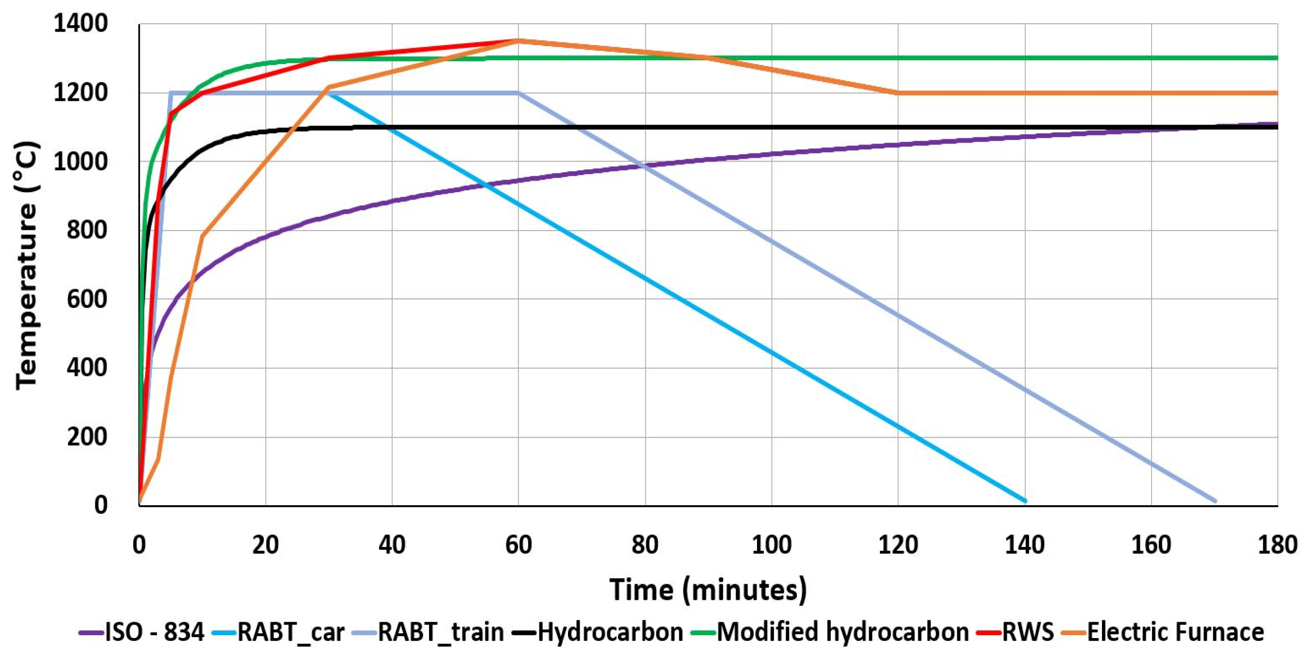
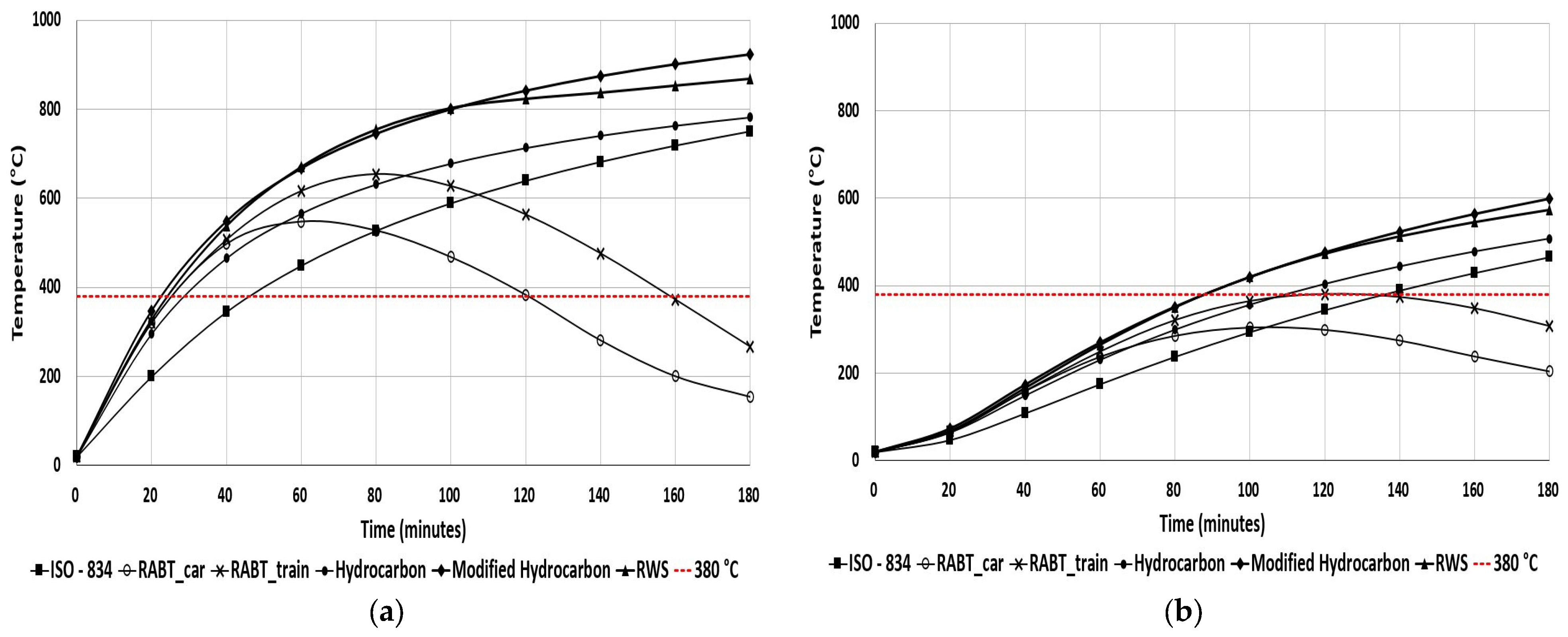
Fire Curves Used for This Study

This study includes the electric furnace fire temperature and international fire curves ISO-834, RABT_ZTV (car), RABT_ZTV (train), hydrocarbon curve, modified hydrocarbon curve, and RWS curve [25]. Equations (1)–(3) represent the ISO-834, hydrocarbon, and modified hydrocarbon fire curves. Table 1 shows the different fires with time and temperature. The ISO-834 curve is a standard fire test to evaluate materials’ fire resistance. The average temperature of the ISO-843 fire curve can be calculated from Equation (1) [26]. The RABT curves, originating from Germany and developed through various test programs, including the Eureka project, exhibit distinctive characteristics. Within the RABT curves, the temperature escalation is notably rapid, reaching up to 1200 °C within 5 min. However, it is essential to note that the duration of exposure to 1200 °C is relatively shorter than other curves. For instance, in the case of car fires, the temperature begins to drop after just 30 min, while for train fires, this drop-off commences at the 60 min mark. These fire curves include a 110 min cooling period as part of their specifications. For the RABT_car and RABT_train fire curves, the rise in temperature until 30 min is the same, so in the figure, these curves overlap until 30 min.
Similarly, the RWS and electric furnace fire curves have the same temperature from 60 to 180 min. Figure 1 shows that the hydrocarbon curve experiences a rapid ascent, stabilizing at 1100 °C within 30 min [27]. The Rijikswaterstaat (RWS) curve, developed by the Ministry of Transport in the Netherlands, is designed to model catastrophic events involving a 50 m3 tanker fire carrying fuel, oil, or petrol with a fire load of 300 MW, lasting for up to 120 min. This curve was established based on testing conducted by TNOs in the Netherlands in 1979. Table 1 and Figure 1 illustrate the RWS fire curve, depicting temperature changes over time. The curve begins with an initial temperature of 20 °C at time zero and gradually increases to 1350 °C over 60 min. After 120 min, the temperature drops to 1200 °C and remains constant until 180 min [28].
T = 20 + 345 × log (8 × t + 1)
T = 20 + 1080 × (1 − 0.325 × e−0.167×t − 0.675 × e−2.5×t)
T = 20 + 1280 × (1 − 0.325 × e−0.167×t − 0.675 × e−2.5×t)
T = temperature in °C and t = time in minutes.

2. Experimental Materials and Methods

2.1. Materials and Mix Proportion

This study used type I ordinary Portland cement [9] along with coarse aggregates (C.A.) with a maximum size of 25 mm. Fine aggregates (F.A.) [9] and superplasticizers were added. A shrinkage-reducing agent (SRA) addressed shrinkage-related concerns and minimized the potential for cracks in the cured concrete [9]. This SRA primarily consisted of a combination of organic surfactants and glycol ether. The water-to-cement ratio in the mixture was 0.5. Table 2 illustrates the mixing proportion of the specimens.

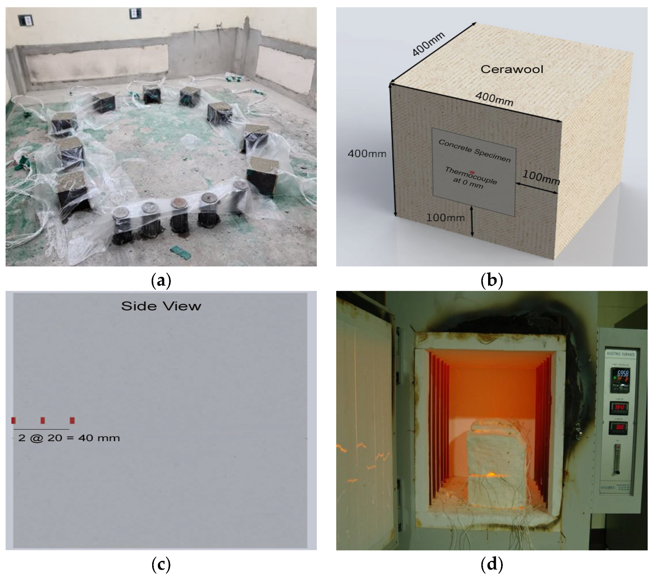
2.2. Experimental Method

Cubical specimens measuring 200 mm × 200 mm × 200 mm were carefully prepared for experimentation. Thermocouples were strategically placed within the specimens, one at 20 mm and another at 40 mm along the central axis. After the curing, five out of six sides of each specimen were covered with cerawool insulation to simulate specific conditions. The compressive strength of the concrete after 28 days of curing was 24 MPa. During the experimental phase, the specimens were subjected to a 3 h heating process inside an electric furnace. The furnace’s temperature was controlled according to a predetermined time–temperature graph, as illustrated in Figure 1. It is worth noting that the interior dimensions of the electric furnace were 600 mm × 600 mm × 600 mm, providing ample space for the specimens. For visual references, refer to Figure 2, which depicts both the experimental specimens and one of them inside the electric furnace during an experiment.

2.3. Simulation Methods

The concrete model was modeled as in the experiment. LS-DYNA finite element software developed by LSTC was used [30]. For modeling purposes, the concrete was represented using the LS-DYNA thermal material model *MAT_THERMAL_ISOTROPIC, and in this approach, the concrete block was modeled with solid elements. The *MAT_THERMAL_ISOTROPIC card allows the definition of the thermal properties of the materials. In this simulation, density, specific heat, and concrete thermal conductivity were taken from the reference [31] and defined at the *MAT_THERMAL_ISOTROPIC model. The experimental electric furnace temperature in Figure 1 was applied from the top surface of the model. To provide the experimental boundary condition for the simulation, expect the temperature applied surface; all sides had insulation boundary conditions. In this study, the concrete’s density, specific heat, and thermal conductivity taken for the simulation were 2400 kg/m3, 1000 J/kg·°C, and 0.31 J/ms·°C, respectively. In addition, different international fire curves ISO-834, RABT_ZTV (car), RABT_ZTV (train), hydrocarbon curve, modified hydrocarbon curve, and RWS curve were applied. A calcium silicate fireproof with a different thickness was added to the top surface of the concrete, and the electric furnace temperature was on the fireproof board. The fireproof board’s specific heat capacity was 800 J/kg °C, the density was 1086 kg/m3, and the thermal conductivity of the fireproof board was 0.252 J/ms·°C [15,16]. Calcium silicate fireproof boards have a thermal conductivity of 0.05–0.24 J/ms·°C [16]. Temperatures with different depths of concrete were analyzed and presented in this study. It was assumed that the fire would last 3 h in all cases. Figure 3 shows the two different models for the simulation.

3. Results

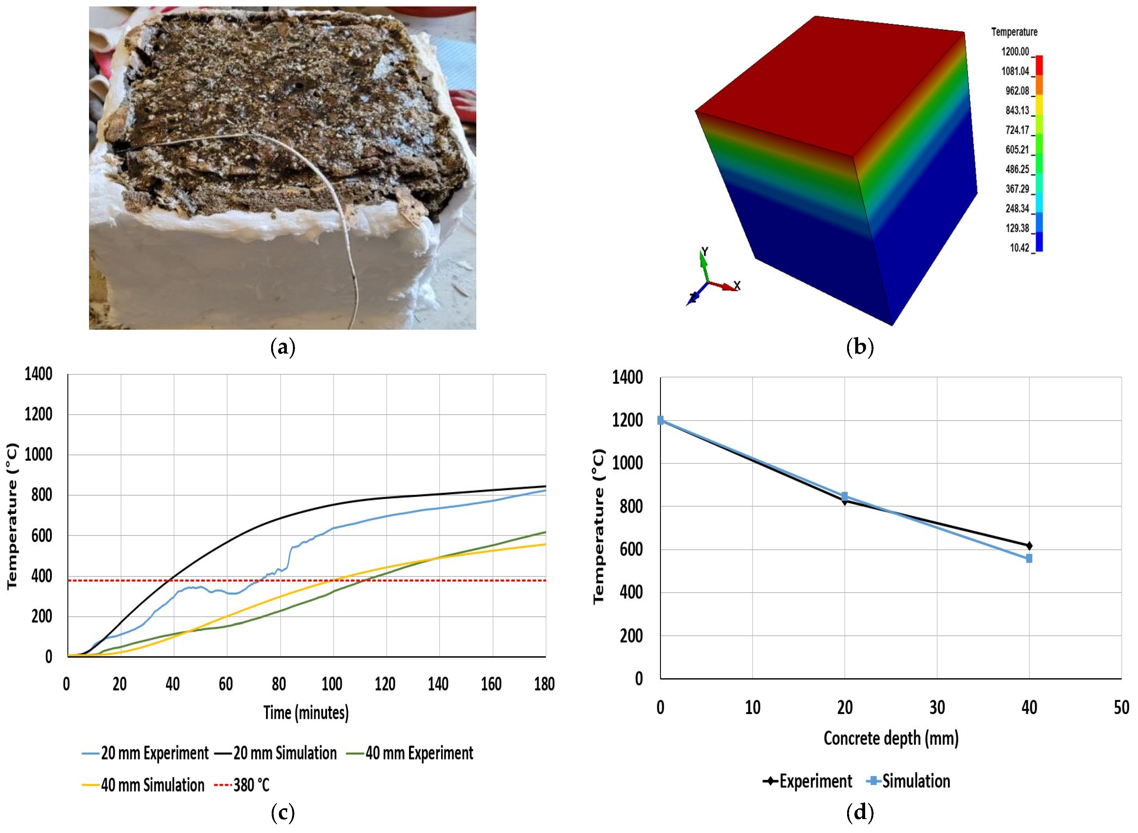
3.1. Experiment and Simulation

The fire curve used for the experiment and simulation is shown in Figure 1. The experimental mix proportion is shown in Table 2, and simulation properties can be found in Section 2.3. Both experiment and simulation were completed for 3 h. In the experiment, the temperature at different depths falls over time and tends to increase later, but in the simulation, the temperature at different depths increases in order. Figure 4a,b represent the specimens from the experiment and simulation after the fire was applied. Current experimental studies do not consider the visual of temperature with different depths, so it can be visualized in Figure 4b. Similarly, the simulation study does not consider the eroding and spalling of the concrete due to the temperature effect; it can be seen from Figure 4a after the fire effect.
Similarly, Figure 4c refers to the experimental and simulation temperature results with time inside concrete depth of 20 mm and 40 mm. A thermocouple was placed inside the concrete during casting to analyze the temperature, and the node temperature was taken from the simulation in the same position. Experimental and simulation temperatures at concrete depths of 20 mm and 40 mm agreed well. The International Tunneling Association (ITA) establishes guidelines for tunnel safety, particularly regarding heat emission and fire duration, to safeguard tunnel structures from fire incidents. These guidelines recommend maintaining a maximum allowable temperature of 380 °C to prevent concrete structure deterioration [32,33]. In both cases, the temperature is over the ITA’s permissible limit of 380 °C in the experiment and simulation with the different concrete depths.

3.2. Simulation Results from Different Fire Curves

After one hour, the electric furnace’s temperature aligns with the RWS fire curve, but it remains lower than the RWS curve up to that point. This study delved deeper into simulation analysis to comprehensively understand temperature behavior in an experimental concrete structure exposed to various international fire curves. Figure 5 illustrates the results of temperature versus time for different concrete depths under different international fire curves. Among the fire curves analyzed, it was noted that the temperature generally decreased as the concrete depth increased from the surface where a fire was applied or occurred. Specifically, when considering the RABT_car fire curve, it was observed that at a concrete depth of 40 mm, the temperature consistently remained below the permissible limit specified by the ITA of 380 °C. During the occurrence of a fire in all cases, the temperature at a depth of 20 mm exceeded the ITA’s permissible limit of 380 °C. However, at a depth of 40 mm, during the fire incidents in all cases except for the RABT_car curve, the temperature exceeded the ITA’s permissible limit of 380 °C. Among the studied fire curves, the temperature was notably higher in the modified hydrocarbon fire curves at both concrete depths. The temperature tends to decrease at RABT_car and RABT_train because the temperature starts to form 30 min and 60 min, respectively. The temperature decline observed in the RABT_car and RABT_train fire curves can be attributed to a reduction in temperature, which initiates at 30 min for RABT_car and 60 min for RABT_train.

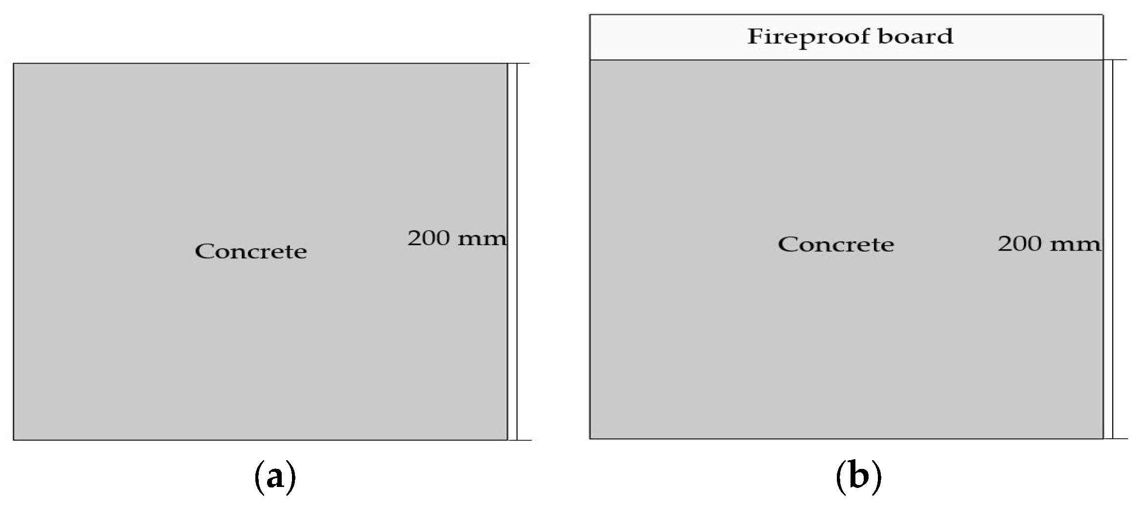
3.3. Simulation Results from Concrete and Fireproof Board

The fireproof board (calcium silicate board) analyzed in reference [15] was considered, and international fire curves were studied to understand the thermal analysis through simulation. The fire curves were applied directly to the surface of the fireproof board, and temperature was analyzed at varying depths within the concrete. Figure 6 illustrates the temperature trends for different concrete depths over time, comparing scenarios with and without fireproof boards. The findings indicated that employing fireproof boards mitigates temperature effects compared to situations where no fireproof boards are used. Among the various international fire curves studied, it was observed that at a concrete depth of 20 mm, temperatures exceed 380 °C in most cases, except for RABT_car and RABT_train. During the ISO-843 fire curve simulation with a fireproof board, the temperature at a depth of 20 mm reached 379 °C after 160 min, while without a fireproof board, the temperature at the same depth reached 379 °C at 46 min. This underscores the conclusion that incorporating fireproof boards can significantly prolong the time it takes to surpass the critical ITA temperature limit. At a concrete depth of 40 mm, fireproof boards effectively kept temperatures below 380 °C during a fire incident. The time required to cross the ITA’s temperature limit was notably extended compared to scenarios without fireproof boards. Furthermore, the time taken to cross the ITA’s temperature threshold for RWS and modified hydrocarbon was found to be similar when fireproof boards were used.
An additional simulation was conducted to determine the required thickness of the fireproof board to maintain a temperature below 380 °C. The thickness of the fireproof board was selected as 24 mm, 30 mm, 35 mm, and 40 mm. Table 3 shows the temperature at a concrete depth of 20 mm with different international fire curves and calcium silicate fireproof board. A 3 h fire exposure was applied to the surface of the fireproof board installed with the concrete. Based on the simulation results, it was observed that a 24 mm fireproof board could not maintain a temperature below the ITA’s temperature limit during the ISO-834 fire curve. However, it increased the time to cross the ITA’s temperature limit from 46.5 min to 160 min. During the occurrence of the RABT_car and RABT_train fire, a 24 mm thickness of fireproof board decreased the thermal effect on concrete. Among the studied fire curves’ effects on concrete, the modified hydrocarbon fire curve had a tremendous negative effect on concrete structure, and the time crossed the ITA’s temperature limit of 23 min. This simulation study concluded that for RABT_car and RABT_train, 24 mm of fireproof board maintained the ITA’s temperature limit, whereas for the ISO-834 and hydrocarbon fire curves, it was 30 mm and 35 mm, respectively. During modified hydrocarbon and RWS fire, a 40 mm thickness of fireproof board decreases the ITA’s temperature limit on concrete at a depth of 20 mm.

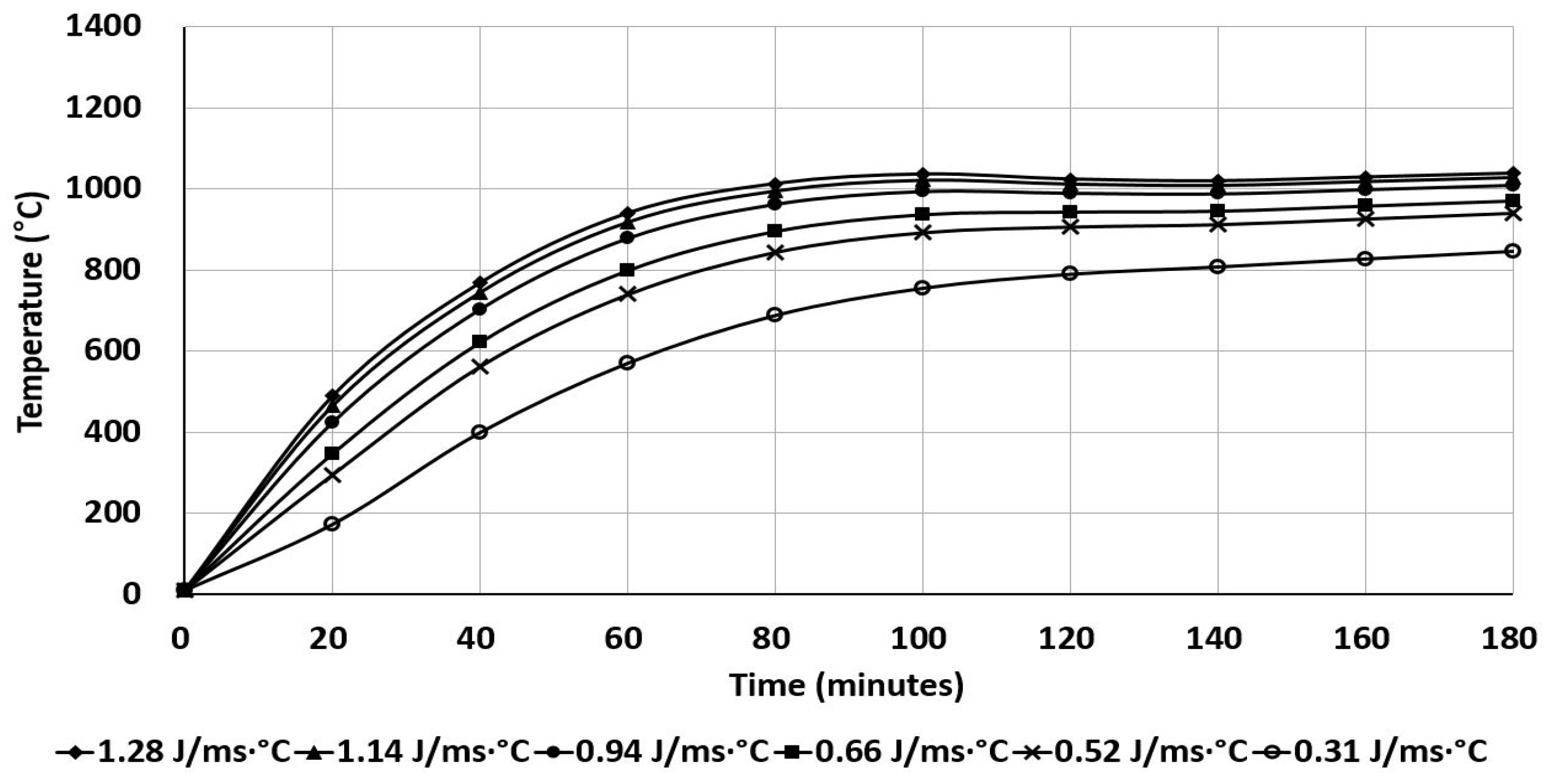
3.4. Thermal Conductivity of Concrete

The thermal properties of the concrete are affected by various properties of concrete. It affects density, aggregate size, specific heat of the concrete, and conductivity. In this study, the thermal properties of the concrete were studied with changes in the conductivity of the concrete structure. Reference [31] calculated the conductivity and specific heat of the concrete with different temperatures. In this study, the different conductivity of the concrete was analyzed with the constant of specific heat (1000 J/kg·°C) and density (2400 kg/m3). The electric furnace temperature was selected for the simulation. Table 4 illustrates the conductivity values analyzed in this study. Figure 7 shows the temperature with a time plot of different conductivities from the simulation. The simulation results confirmed that lower concrete conductivity decreases the temperature inside the concrete depth when exposed to fire. In this study, the temperature at 20 mm concrete depth from the surface of the concrete was lower at a conductivity of 0.31 J/ms·°C.

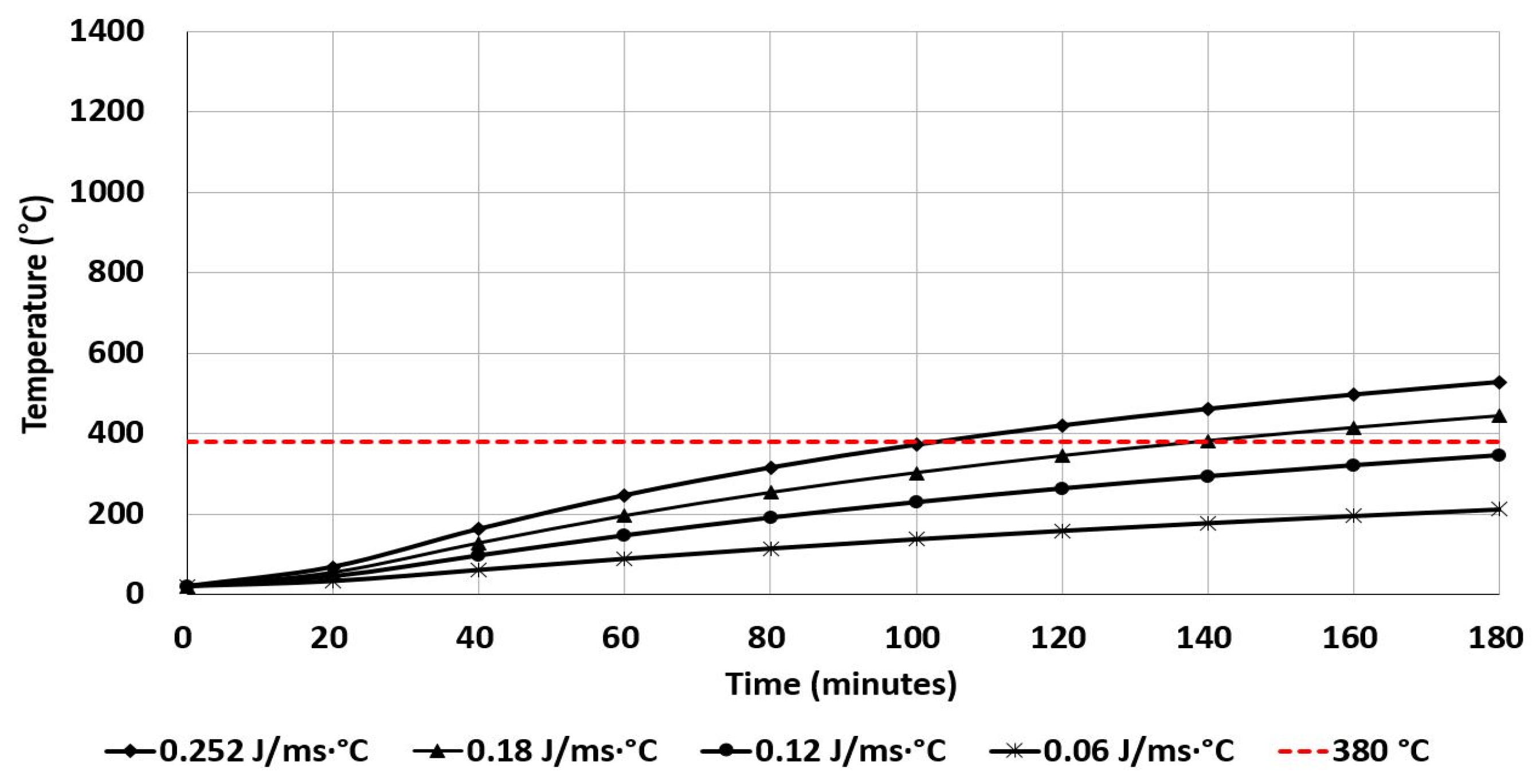
3.5. Thermal Conductivity of Calcium Silicate Fireproof Board

From the above simulation results, the modified hydrocarbon fire curve had a high-temperature effect on concrete. In this section, the modified hydrocarbon fire curve was selected for addition simulation analysis. The fireproof boards had a specific heat capacity of 800 J/kg·°C, a density of 1086 kg/m3, and a thermal conductivity of 0.252 J/ms·°C [15,16]. Calcium silicate fireproof boards have a thermal conductivity of 0.05–0.24 J/ms·°C [16]. This section analyzes the effect on concrete due to the change in thermal conductivity of fireproof boards. The researcher studied the experimental and numerical simulation of the tube structure of a steel–concrete–steel-immersed tube tunnel under the RABT tunnel fire heating curve. After applying the fireproof board, the maximum surface temperature of the bottom steel plate was lowered from 1200 °C to 264.59 °C [16]. Figure 6 illustrates that using a 24 mm thick fireproof board reduces the temperature below 380 °C on concrete during the occurrence of fire at a depth of 40 mm. During a fire occurrence for 3 h, to maintain the temperature below 380 °C, a 40 mm thick fireproof board was used for the modified hydrocarbon and RWS curves. In general, as the thickness of fireproof boards increases, so does their fire insulation effectiveness. However, this leads to an increase in the weight of the fireproof boards, raising the mounting system’s demands.
Additionally, the expanded dimensions of the fireproof boards result in reduced available space. These factors collectively contribute to higher engineering costs. Consequently, it is imperative to minimize the thickness of fireproof boards while still ensuring adequate fire insulation performance [16]. So, in this section, the different conductivity of the fireproof board had been applied to 24 mm thickness installed with concrete and the concrete temperature at a depth of 20 mm at a modified hydrocarbon fire curve. Table 5 illustrates the conductivity values analyzed in this study. The numerical simulation results confirmed that with a decrease in the conductivity of the fireproof board, the effect of the fire on the concrete decreased. Figure 8 shows the temperature distribution on concrete structure at a depth of 20 mm. When the conductivity of the fireproof board was 0.12, the temperature was below the ITA’s limit, i.e., 380 °C. It was confirmed that selecting a fireproof board with low conductivity is a better option than increasing the thickness of the fireproof board during installation with concrete tunnel lining.

4. Discussion

In this study, during the experiment, the temperature inside the concrete was measured with a thermocouple inside the electric furnace. The current experimental study did not consider spalling and displacement under temperature effects. Similarly, the temperature inside the concrete under the effect of different international fire curves was studied through simulation. The prepared concrete block with mixing materials crossed the ITA’s temperature limit of 40 mm from experimental and simulation results. During fire occurrence for all cases, the temperature at a depth of 20 mm exceeds the ITA’s permissible limit of 380 °C. However, during fire occurrence for all cases except RABT_car, the temperature at a depth of 40 mm exceeds the ITA’s permissible limit of 380 °C. Among international fire curves studied through simulation at a concrete depth of 20 mm, the temperature is over 380 °C, which exceeds the ITA’s permissible limit except for RABT_car and RABT_train. During the ISO-843 fire curve with the fireproof board, the temperature at a depth of 20 mm at 160 min is 379 °C, whereas, without a fireproof board at 46 min, the temperature at 20 mm is 379 °C. It was concluded that using a fireproof board increases the time to cross the ITA’s limit temperature of the structure. The use of 24 mm of fireproof board had a lower temperature at different depths than those without fireproof board. It was concluded that using a fireproof board decreases the thermal damage to the concrete structure and increases the time to cross the ITA’s limit. Among the simulations of international fire curves, modified hydrocarbon had a high temperature at different concrete depths. Modified hydrocarbon and RWS had similar temperature rises at different depths during the occurrence of fire. RABT_car and RABT_train fire curves tend to decrease the temperature after 63 min and 78 min, respectively, at a concrete depth of 20 mm without a fireproof board because of the fire curve nature. Others remain increasing. In general, as the thickness of fireproof boards increases, so does their fire insulation effectiveness. However, this leads to an increase in the weight of the fireproof boards, raising the mounting system’s demands.
Additionally, the expanded dimensions of the fireproof boards result in reduced available space. These factors collectively contribute to higher engineering costs. Consequently, it is imperative to minimize the thickness of fireproof boards while still ensuring adequate fire insulation performance [16]. The different conductivity of the fireproof board was applied to 24 mm thickness installed with concrete and the concrete temperature at a depth of 20 mm at a modified hydrocarbon fire curve. The numerical simulation results confirmed that with a decrease in the conductivity of the fireproof board, the effect of the fire on the concrete decreased.

5. Conclusions

The thermal behavior of concrete was studied through experimental and simulation methods. Notably, the experimental results for concrete depths of 20 mm and 40 mm demonstrated excellent alignment with the simulation results. Furthermore, a fireproof board was used to mitigate temperature elevations within the concrete depth during fire incidents. The analysis delved into the temperature variations within the concrete under different fire curves. The following are the key conclusions drawn from this study.
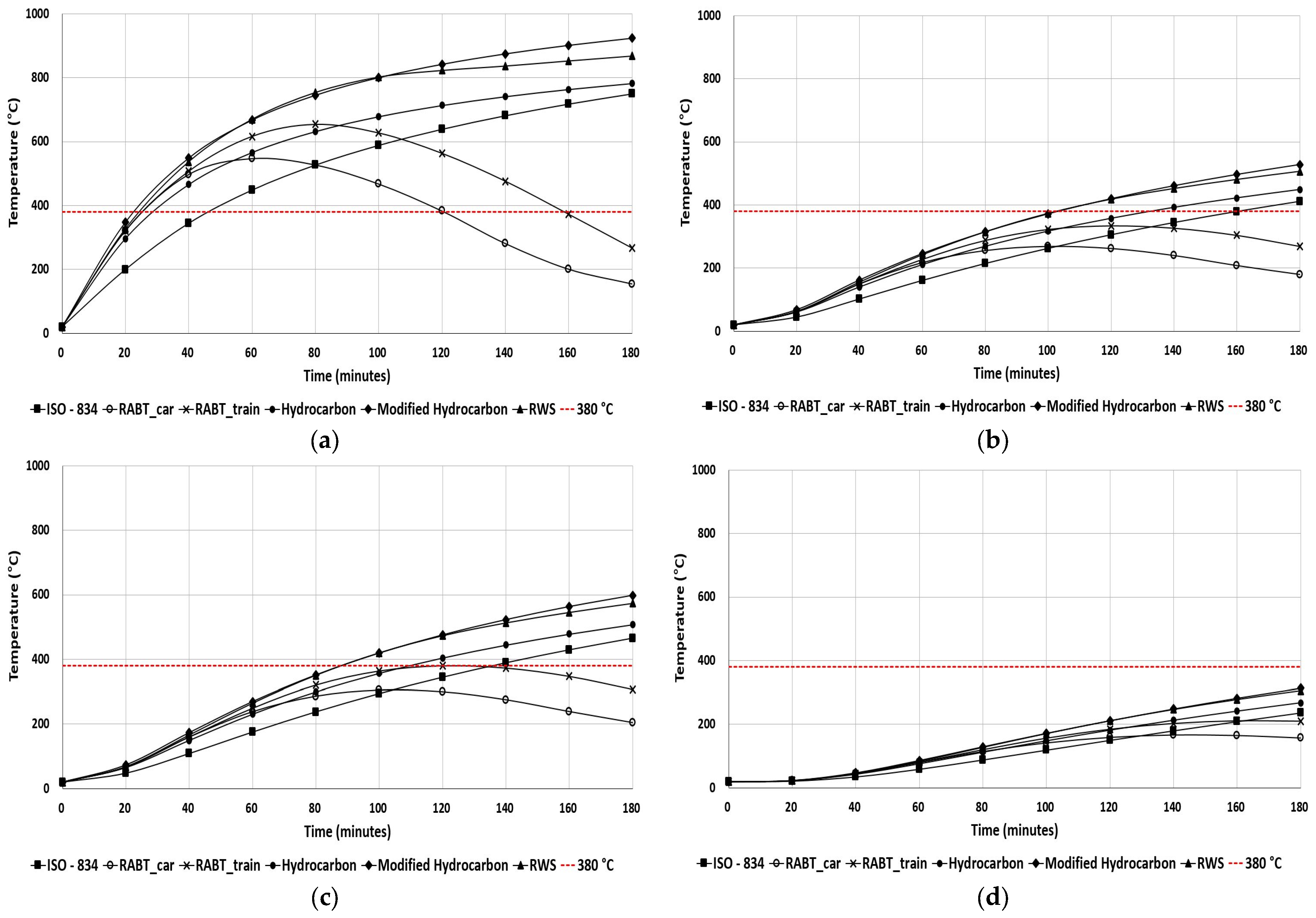
  • In experimental and simulation results, the concrete blocks prepared by mixing materials exceeded the ITA’s temperature limit up to a depth of 40 mm. When a fire occurred, in all cases, temperatures at a depth of 20 mm surpassed the permissible ITA limit of 380 °C. However, it is worth noting that except for the RABT_car case, temperatures at a depth of 40 mm exceeded the ITA’s permissible limit of 380 °C during the fire incidents.
  • Among international fire curves studied through simulation at a concrete depth of 20 mm, the temperature is over 380 °C, which exceeds the ITA’s permissible limit except for RABT_car and RABT_train.
  • During the ISO-843 fire curve with a fireproof board, the temperature at a depth of 20 mm at 160 min is 379 °C, whereas, without a fireproof board at 46 min, the temperature at 20 mm is 379 °C. It was concluded that using a fireproof board increases the time to cross the ITA’s structure temperature limit.
  • In the simulation of international fire curves, the modified hydrocarbon exhibited elevated temperature at various depths within the concrete. Interestingly, when subjected to fire, the modified hydrocarbon and RWS displayed a comparable temperature increase at different depths. However, it is worth noting that the RABT_car and RABT_train fire curves tended to decrease the temperature after 63 and 78 min, respectively, specifically at a concrete depth of 20 mm. This temperature decrease is attributed to the inherent characteristics of the fire curve. In contrast, the temperature at other depths continued to rise steadily.
  • For concrete and fireproof boards, the selection of low-conductivity materials is directly proportional to the low thermal effect on tunnel lining due to fire accidents. Numerical simulation results confirmed that reducing the conductivity of the fireproof board led to a decrease in the fire’s effect on the concrete. This study confirms that selecting a 24 mm thick fireproof board with a conductivity of less than 0.12 J/ms·°C was suitable for reducing the negative temperature effect on concrete.

Author Contributions

Conceptualization, T.O., C.P., G.K. and S.K.; methodology, T.O., C.P., G.K. and S.K.; software, T.O., C.P., G.K. and S.K.; validation, T.O., C.P., G.K. and S.K.; writing—original draft preparation, T.O., D.H., T.J., C.P., G.K. and S.K.; writing—review and editing, T.O., D.H., T.J., C.P., G.K. and S.K.; All authors have read and agreed to the published version of the manuscript.

Funding

This research was supported by a 2021 research grant from Kangwon National University and “Regional Innovation Strategy (RIS)” through the National Research Foundation of Korea (NRF) funded by the Ministry of Education (MOE) (2022RIS-005).

Institutional Review Board Statement

Not applicable.

Informed Consent Statement

Not applicable.

Data Availability Statement

Data are contained within the article.

Conflicts of Interest

The authors declare no conflicts of interest.

References

  1. Yoshitake, I.; Baba, K.; Ito, T.; Nakagawa, K. Behavior of Fiber Reinforced Concrete Under Fire. HPFRCC Workshop Honol. 2005, 3, 1–6. [Google Scholar]
  2. Sakkas, K.; Vagiokas, N.; Tsiamouras, K.; Mandalozis, D.; Benardos, A.; Nomikos, P. In-Situ Fire Test to Assess Tunnel Lining Fire Resistance. Tunn. Undergr. Space Technol. 2019, 85, 368–374. [Google Scholar] [CrossRef]
  3. Geography of Korea—Wikipedia. Available online: https://en.wikipedia.org/wiki/Geography_of_Korea (accessed on 11 April 2023).
  4. Road Bridge and Tunnel Status Information System. Available online: https://bti.kict.re.kr/bti/publicMain/main.do (accessed on 5 October 2023).
  5. Choi, S.; Kim, G.; Jang, T.; Oli, T.; Kim, S.; Park, C. Tensile Behavior Analysis of Rebar Exposure to High Temperature for Tunnel Fire Damage Diagnosis Method. In Proceedings of the Annual Korean Socity of Road Engineers Conference, Jeju, Republic of Korea, 4–7 October 2022; p. 99. [Google Scholar]
  6. Won, J.-P.; Choi, M.; Jang, C.-I.; Lee, S. Applied Time-Temperature Curve for Safety Evaluation in the Road Tunnel by Fire. KSCE J. Civ. Environ. Eng. Res. 2009, 29, 551–555. [Google Scholar]
  7. Kim, H.J.; Kim, H.Y.; Lee, J.S.; Kwan, K.H. An Experimental Study on Thermal Damage and Spalling of Concrete under Loading Conditions in a Tunnel Fire. J. Asian Archit. Build. Eng. 2011, 10, 375–382. [Google Scholar] [CrossRef]
  8. Fletcher, I.A.; Welch, S.; Torero, J.L.; Carvel, R.O.; Usmani, A. Behaviour of Concrete Structures in Fire. Therm. Sci. 2007, 11, 37–52. [Google Scholar] [CrossRef]
  9. Kim, S.; Oli, T.; Park, C. Effect of Exposure to High Temperature on the Mechanical Properties of SIFRCCs. Appl. Sci. 2020, 6, 2142. [Google Scholar] [CrossRef]
  10. Sanket, R.; Aniruddha, T.; Bahurudeen, A.; Appari, S. Performance of Concrete During Fire Exposure-A Review. Int. J. Eng. Res. Technol. 2015, 4, 1–8. [Google Scholar]
  11. Khoury, G.A. Effect of Fire on Concrete and Concrete Structures. Prog. Struct. Eng. Mater. 2000, 2, 429–447. [Google Scholar] [CrossRef]
  12. Helene, P.; Britez, C.; Carvalho, M. Fire Impacts on Concrete Structures. A Brief Review. Rev. Alconpat 2019, 10, 1–21. [Google Scholar] [CrossRef]
  13. Bilodeau, A.; Kodur, V.K.R.; Hoff, G.C. Optimization of the Type and amount of Polypropylene Fibres for Preventing the Spalling of Lightweight Concrete Subjected to Hydrocarbon Fire. Cem. Concr. Compos. 2004, 26, 163–174. [Google Scholar] [CrossRef]
  14. Do, C.T.; Bentz, D.P.; Stutzman, P.E. Microstructure and Thermal Conductivity of Hydrated Calcium Silicate Board Materials. J. Build. Phys. 2007, 31, 55–67. [Google Scholar] [CrossRef]
  15. Li, J.; Cao, P.; Jiang, S.; Zhang, D. Fire Resistance Test and Numerical Simulation on the Tube Structure of Steel–Concrete–Steel Immersed Tube Tunnel. Buildings 2023, 13, 33. [Google Scholar] [CrossRef]
  16. Hu, X.; Jiang, S.; Zhang, D.; Wang, J. Experimental Study on Fireproof Board Insulation Technique for Steel-Concrete-Steel Immersed Tunnel. Case Stud. Therm. Eng. 2023, 49, 103266. [Google Scholar] [CrossRef]
  17. Laím, L.; Rodrigues, J.P.C. Fire Protection of Reinforced-Concrete Tunnel Linings with Expanded-Clay. Stud. Res. Annu. Rev. Struct. Concr. 2012, 31, 12. [Google Scholar]
  18. Huo, J.; Xiao, Y.; Ren, X.; Zeng, X. A New Hybrid Heating Method Used in Fire Test. Exp. Therm. Fluid Sci. 2015, 62, 52–57. [Google Scholar] [CrossRef]
  19. Ezziane, M.; Kadri, T.; Molez, L.; Jauberthie, R.; Belhacen, A. High Temperature Behaviour of Polypropylene Fibres Reinforced Mortars. Fire Saf. J. 2015, 71, 324–331. [Google Scholar] [CrossRef]
  20. Hua, N.; Elhami Khorasani, N.; Tessari, A.; Ranade, R. Experimental Study of Fire Damage to Reinforced Concrete Tunnel Slabs. Fire Saf. J. 2022, 127, 103504. [Google Scholar] [CrossRef]
  21. Shapiro, A.B. Heat Transfer in LS-DYNA. In Proceedings of the 5th European LS-DYNA Users Conference, Birmingham, UK, 25–26 May 2005; p. 2a-14. [Google Scholar]
  22. Rackauskaite, E.; Flint, G.; Maani, A.; Temple, A.; Kotsovinos, P. Use of LS-DYNA for Structural Fire Engineering. In Proceedings of the 12th European LS-DYNA Users Conference, Koblenz, Germany, 14–16 May 2019. [Google Scholar]
  23. Ma, Z.; Havula, J.; Heinisuo, M. Structural Fire Analysis of Simple Steel Structures by Using LS-DYNA. Raken. Mek. 2019, 52, 1–22. [Google Scholar] [CrossRef]
  24. Rackauskaite, E.; Kotsovinos, P.; Rein, G. Model Parameter Sensitivity and Benchmarking of the Explicit Dynamic Solver of LS-DYNA for Structural Analysis in Case of Fire. Fire Saf. J. 2017, 90, 123–138. [Google Scholar] [CrossRef]
  25. International Fire Curves and Fire Safety Design—Promat. Available online: https://www.promat.com/en/tunnels/your-project/expert-area/159981/international-fire-curves-fire-safety/ (accessed on 5 October 2023).
  26. ISO 834-1:1999; Fire-Resistance Tests—Elements of Building Construction—Part 1: General Requirements. ISO: Geneva, Switzerland, 1999. Available online: https://www.iso.org/standard/2576.html (accessed on 6 October 2023).
  27. Oliveira, P.N.; Fonseca, E.M.M.; Campilho, R.D.S.G.; Piloto, P.A.G. Analytical Equations Applied to the Study of Steel Profiles under Fire According to Different Nominal Temperature-Time Curves. Math. Comput. Appl. 2021, 26, 48. [Google Scholar] [CrossRef]
  28. Sakkas, K.; Sofianos, A.; Nomikos, P.; Panias, D. Behaviour of Passive Fire Protection K-Geopolymer under Successive Severe Fire Incidents. Materials 2015, 8, 6096–6104. [Google Scholar] [CrossRef] [PubMed]
  29. Highway Construction Material Quality Standards: 21st Revision—Technical Information Construction Technology Information System CODIL. Available online: https://www.codil.or.kr/viewDtlConWrkDtlSch.do?gubun=tch&pMetaCode=CIGCEI220049 (accessed on 8 November 2023).
  30. LSDYNA Download/Install Overview. Available online: https://lsdyna.ansys.com/download-install-overview/ (accessed on 8 November 2023).
  31. Palm, J. Temperature Analysis Using ABAQUS. Fire Technol. 1994, 30, 291–303. [Google Scholar] [CrossRef]
  32. Guidelines for Structural Fire Resistance for Road Tunnels. Available online: https://about.ita-aites.org/publications/wg-publications/100-guidelines-for-structural-fire%02resistance-for-road-tunnels (accessed on 29 November 2023).
  33. Kim, S.; Shim, J.; Rhee, J.Y.; Jung, D.; Park, C. Temperature Distribution Characteristics of Concrete during Fire Occurrence in a Tunnel. Appl. Sci. 2019, 9, 4740. [Google Scholar] [CrossRef]
  34. Jiang, J.; Main, J.A.; Sadek, F.; Weigand, J.M. Numerical Modeling and Analysis of Heat Transfer in Composite Slabs with Profiled Steel Decking; National Institute of Standards Technology: Gaithersburg, MD, USA, 2017; pp. 1–56. [Google Scholar]
Figure 1. Different fire curves.
Fire 07 00015 g001
Figure 2. (a) Specimens inside mold; (b) concrete specimens with cerawool; (c) side view with a position of the thermocouple; (d) specimen inside the electric furnace.
Fire 07 00015 g002
Figure 3. Simulation variables model. (a) Concrete model; (b) concrete model with installation of fireproof board on top.
Fire 07 00015 g003
Figure 4. Experimental and simulation temperature with time plot with different concrete depths. (a) Experimental specimen after applied fire; (b) simulation specimen after applied fire (temperature in °C); (c) experimental and simulation temperature with time plot at different concrete depth; (d) temperature with concrete depth at time 180 min.
Fire 07 00015 g004
Figure 5. Concrete depth temperature with time of different international fire curves (a) 20 mm; (b) 40 mm.
Fire 07 00015 g005
Figure 6. With and without fireproof board temperatures at different depths with time: (a) without fireproof board at a depth of 20 mm; (b) with fireproof board at a depth of 20 mm; (c) without fireproof board at a depth of 40 mm; (d) with fireproof board at a depth of 40 mm.
Fire 07 00015 g006
Figure 7. Temperature at the concrete depth of 20 mm at electric furnace temperature with different thermal conductivity.
Fire 07 00015 g007
Figure 8. Temperature at a concrete depth of 20 mm with fireproof board during modified hydrocarbon fire curve with different thermal conductivity.
Fire 07 00015 g008
Table 1. Different fires with temperatures [25].
Fire CurveTime (min)Temperature °C
RABT_train015
51200
601200
17015
RABT_car015
51200
301200
14015
RWS020
3890
51140
101200
301300
601350
901300
1201200
1801200
Table 2. Mix proportion for the concrete [29].
VariableW/C (%)S/a (%)Unit Weight (kg/m2)
WCF.A.C.A.AE
Concrete504216733473910481.002
Table 3. Simulation temperature distribution of concrete depth at 20 mm with different international fire curves and calcium silicate fireproof board.
Fire CurveThickness of Fireproof Board Plate (mm)Time to Cross ITA’s Limit (min)Remarks
ISO-834Without fireproof board46.5Cross ITA’s temperature limit
24160
30-Below ITA’s temperature limit
35-
40-
RABT_carWithout fireproof board25Cross ITA’s temperature limit
24-Below ITA’s temperature limit
30-
35-
40-
RABT_trainWithout fireproof board25Cross ITA’s temperature limit
24-Below ITA’s temperature limit
30-
35-
40-
HydrocarbonWithout fireproof board28.5Cross ITA’s temperature limit
24133
30169
35-Below ITA’s temperature limit
40-
Modified
Hydrocarbon
Without fireproof board23Cross ITA’s temperature limit
24103.5
30131.5
35156
40-Below ITA’s temperature limit
RWSWithout fireproof board24.5Cross ITA’s temperature limit
24103.5
30133.5
35162
40-Below ITA’s temperature limit
Table 4. Simulation variables.
S.No.Conductivity (J/ms·°C) [31]Specific Heat (J/kg·°C) [31,34]
11.281000
21.14
30.94
40.66
50.52
60.31
Table 5. Simulation variables for the fireproof board.
S.No.Conductivity (J/ms·°C) [15,16]Specific Heat (J/kg·°C) [15]
10.06800
20.12
30.18
40.252
Disclaimer/Publisher’s Note: The statements, opinions and data contained in all publications are solely those of the individual author(s) and contributor(s) and not of MDPI and/or the editor(s). MDPI and/or the editor(s) disclaim responsibility for any injury to people or property resulting from any ideas, methods, instructions or products referred to in the content.

