Article

Simulation of RC Beams during Fire Events Using a Nonlinear Numerical Fully Coupled Thermal-Stress Analysis

by
Mohamed Elshorbagi
1 and
Mohammad AlHamaydeh
2,*
1
School of Engineering, Design and Built Environment, Western Sydney University, Penrith, NSW 2751, Australia
2
Department of Civil Engineering, College of Engineering, American University of Sharjah, Sharjah P.O. Box 26666, United Arab Emirates
*
Author to whom correspondence should be addressed.
Submission received: 23 December 2022 / Revised: 31 January 2023 / Accepted: 1 February 2023 / Published: 7 February 2023
(This article belongs to the Special Issue Fire Numerical Simulation)

Abstract

:
The collapse and deterioration of infrastructures due to fire events are documented annually. These fire incidents result in multiple deaths and property loss. In this paper, a reliable and practical numerical methodology was introduced to facilitate the whole process of fire simulations and increase the practicality of performing comprehensive parametric studies in the future. These parametric studies are crucial for understanding the factors that affect thermal–structural responses and avoiding the high cost of destructive tests. The proposed algorithm comprises a fully nonlinear coupled thermal-stress analysis involving thermal and structural material nonlinearity and the thermal–structural response during a fire. A detailed numerical modeling analysis was performed with ABAQUS to achieve the proposed algorithm. The results of the proposed numerical methodology were validated against published experimental work. The experimental work includes a full-scale RC beam loaded with working loads and standard heating conditions to simulate real-life scenarios. The tested beam failed during the fire, and its fire resistance was recorded. The results demonstrated a good correlation with the experimental results in thermal and structural responses. Moreover, this paper presents the direct coupling technique (DCT) and the advantages of using DCT over the traditional sequential coupling technique (SCT).

1. Introduction

In 2018, the international association of fire and rescue services (CTIF) [1] recorded over 4.5 million fire events, with over 30.8 thousand deaths in forty-six countries. Moreover, in the United States, the average annual property loss for 2014–2018 is over 10 billion dollars, as reported by the national fire protection association (NFPA) [2]. Hence, it is apparent that controlling structural fire damage is mandatory to mitigate property loss and deaths. This paper aims to reach a feasible simulation analysis technique for fire events and to study the parameters that affect a coupled thermal–structural response later in future studies. This can assist in understanding the destructive influence of wildfires and, consequently, result in the development of optimized structural design against fire.
The main concern relating to fire events is their classification (moderate or severe) and the evaluation of their impact on the structures. The classification of the fire assists in determining whether the structure is reusable or not after the extinguishment of the fire. The reason for the complexity of estimated residual structural capacity is its dependency on an enormous number of factors, such as mechanical pre-load during the fire, peak fire temperature, fire duration, degradation of thermal and mechanical properties of concrete and reinforcement, and boundary conditions of the structure, besides knowing the fact that not all material properties are reversible or valid during the heating, cooling, and post-fire loading stages.
Research efforts to achieve structural safety and evaluate structural performance have been in demand recently due to the high capital investment in buildings and infrastructure sectors. The residual capacity for any structural element can be determined through destructive tests and non-destructive approaches. For the destructive test of reinforced concrete (RC) beams, many researchers [3,4,5,6] have conducted and reported results of experimental tests using standard fires or parametric fires [7]. For example, Enu and Yeong [3] tested a group of beams to evaluate the effect of changing concrete cover thickness, strength, pre-load value, and heating time on structural and thermal responses. They found that the reduction rate of stiffness and carrying load capacity can be expressed as an exponential function with heating time. Additionally, Yamin and Chuanguo [4] performed full-scale experimental testing of RC beams with different longitudinal reinforcement and stirrups ratios. All beams were designed with the principle of strong bending and weak shearing, and it was concluded that failure might switch to shear-bend failure instead of shear failure at high temperatures. Yuye and Bo [5] tested rectangular and T-shaped RC beams under a ISO834 standard fire and checked the validity of the plane section assumption. They evaluated the decrease in carrying load capacity and the corresponding difference in the case of T-sections due to the flange’s effect. Moreover, Alaa and Hemdan [6] investigated normal-strength concrete (NSC) and high-strength concrete (HSC) beams to study the effect of fire exposure time, concrete cover, compressive strength, and cooling techniques (air or water). They concluded a negligible effect of the concrete compressive strength on the percentage of reduction in ultimate load; however, on the contrary, they concluded a significant effect for the cooling technique.
On the other hand, researchers have also evaluated beams under fire loads using non-destructive approaches [8,9,10,11,12], subdivided into two categories. The first one is the structural response through a simplified cross-sectional analysis, and this is the next step for most of the international codes; instead of using the tabulated data, minimum concrete cover and minimum dimensions to obtain the specified fire resistance as per ACI-216 [13] or ASCE-29-05 [14]. While the second category is used to evaluate the response of RC elements under fire through the finite element models of ABAQUS [15], ANSYS [16], or SAFIR [17] programs.
Researchers M. Elshorbagi and M. Mooty [8] proposed nonlinear finite element models to assess the RC beams’ thermal and structural responses using the ANSYS program. Furthermore, they [9] studied the effects of compressive strength, concrete cover, and lateral stiffness on RC beam responses under fire events. They evaluate the significant impact on fire resistance due to increased concrete cover and lateral stiffness. ANSYS was also utilized by Lili and Zhenqing [10] to study the residual capacity of RC elements under different fire scenarios. Firstly, thermal contours over member cross-sections were obtained, followed by the equivalent cross-section economization method to consider the fire-induced damage by reducing the rebar and concrete cross-sections. Moreover, they evaluated the effect of some parameters on the structural and thermal responses. For example, it was concluded that both concrete compressive strength and reinforcement strength had a minor effect on residual capacity. Conversely, the cross-sectional dimensions had more significant effects. Moreover, among all the studied parameters, the most influential one was the thickness of the fire protection layer, as it had the most significant impact on the residual capacity. Rui and Bo [11] aimed to obtain the full thermal–structural response of RC beams with two integrated models. The first model was used to define the thermal response with a 2D thermal finite element model, and the second model was used to obtain the mechanical response using a one-dimensional spectral numerical model. The results (mid-span deflection versus time, applied load) were in good agreement, despite using many assumptions, such as a perfect bond, which reflects the insignificance of accounting interfacial relations in some cases.
This paper mainly emphasizes the direct coupling technique (DCT), coupled elements, and how to apply it to fire events to fill the existing gap in the literature regarding DCT. As previously mentioned, most numerical simulations for structural elements under different fire scenarios implement either the sequential coupling technique (SCT) or simplified 2D models. This paper aims to study RC beams under fire conditions using DCT, and the same concept can be replicated with other research software packages such as ANSYS.
Despite the wide use of SCT [18,19,20], it has many disadvantages. It is adopted in almost every fire-related numerical simulation due to its relative simplicity and non-prohibitive computational demands. The DCT is expected to be a game-changer in many aspects, as many cases cannot even be modeled with SCT. One of the most common problems that has not been addressed yet is the significant deficiency of SCT in modeling any scenario that involves significant geometry change. This is due to the absence of a continuous link between thermal and structural analyses. On the other hand, DCT can be used very efficiently to model such cases, and one of the most crystal-clear applications for this is modeling any intumescent coatings. Intumescent coating is considered one of the most efficient ways of fire protection and one of the hottest topics when it comes to fire protection.

2. Materials and Methods

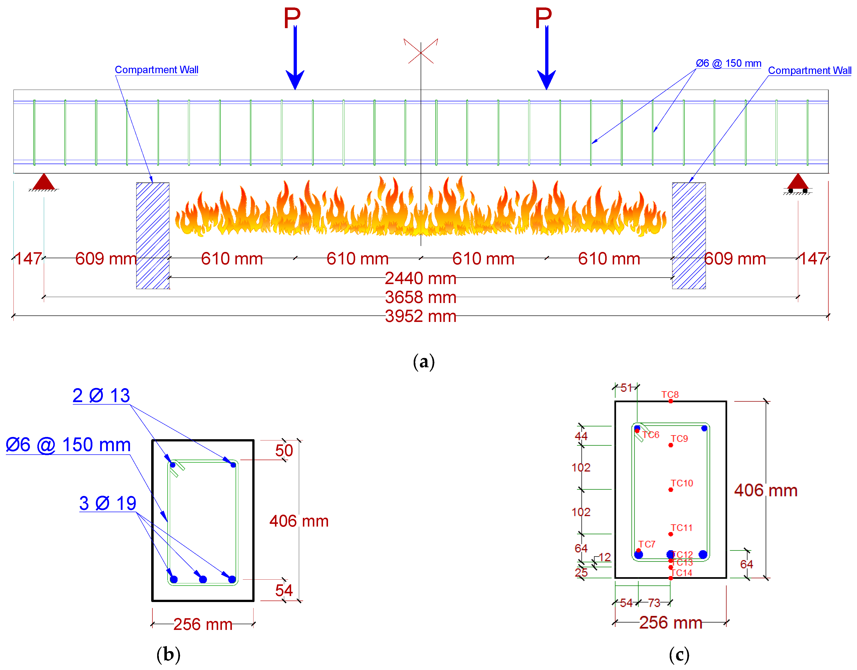
2.1. Experimental Program

The experimental work presented by Dwaikat and Kodur [21] was used to verify the results. They investigated full-scale beam B1 under the standard fire scenario ASTM E119 [22]. The beam’s length, width, and depth were 3960, 254, and 406 mm, respectively, and were cast using NSC. The beam had three 19 mm diameter bars for tension and two 13 mm diameter bars for compression. The shear reinforcement was 6 mm stirrups with 150 mm spacing along the beam length. The compressive strength was 58.2 MPa on the testing day, and the longitudinal reinforcement and stirrups yield strengths were 420 and 280 MPa, respectively. Figure 1 displays the beam geometry, loads land support location, main reinforcement configuration, stirrups spacing, and cross-section details.
To measure the temperature during the entire fire duration for both concrete and the reinforcement, thermocouples were placed at the specified points inside and outside the beam, as depicted in Figure 1. Displacement transducers were used to obtain the vertical deflection at the midsection and load locations. A loading frame (supported on four steel columns) was used to apply the working loads, which was kept constant during the furnace’s ignition and fire duration to simulate the real-life scenario for typical beams in buildings. The used fire chamber had a length, width, and height of 3050, 2440, and 1680 mm, respectively, and can produce up to 2.5 MW using six natural gas burners. Six thermocouples were distributed inside the furnace to manually monitor and control thermal energy to fit the desired simulated fire scenario by adjusting the fuel supply.
The beam was placed inside the testing furnace and subjected to mechanical loads, followed by the application of thermal loads. Beam B1 had a clear span and exposed fire span of 3660 and 2440 mm, respectively. As shown in Figure 1a, B1 was loaded with two-point loads of 50 kN each (working load) and ASTM E119 [19] fire curve, and it was determined to have failed after 180 min of testing. This working load is approximately 55% of the ultimate load, according to ACI 318 [23]. After reaching the initial mechanical loads, the load was kept constant for 30 min to stop further beam deformation before activation of the fire chamber. This deflection is the initial condition for the thermal loading step. On the other hand, the mechanical load was maintained during the fire loading step, and the beam was considered to reach failure when the hydraulic jack failed to maintain the load.

2.2. General Analysis Procedures

The proposed methodology was based on a detailed numerical finite element model developed with the ABAQUS program, and DCT was chosen to join the thermal and structural analysis. Generally, two types of coupling techniques are available to connect thermal and structural analyses: SCT or DCT. SCT is based on running a thermal analysis and implementing these results into a structural analysis [8,9], as illustrated in Figure 2a. On the other hand, for DCT, one model can perform thermal and structural analysis, as coupled elements can express both the thermal and the structural degrees of freedom (DOFs), as shown in Figure 2b. Convection loads are used to apply fire loads on different areas for the beam with film coefficients to simulate the desired fire scenario and determine the surfaces in direct contact with the fire. The convection loads vary with time according to the applied fire curve (Temperature vs. Time curve).
The beams were analyzed for mechanical and fire loads. The analysis included the following steps:
1.
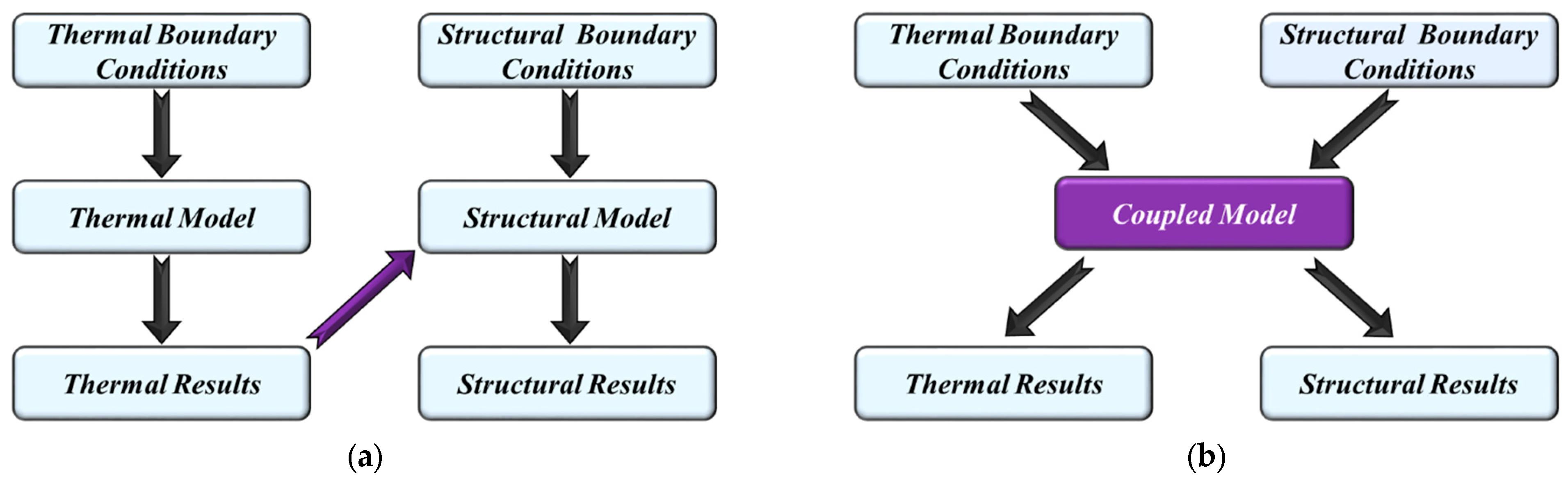
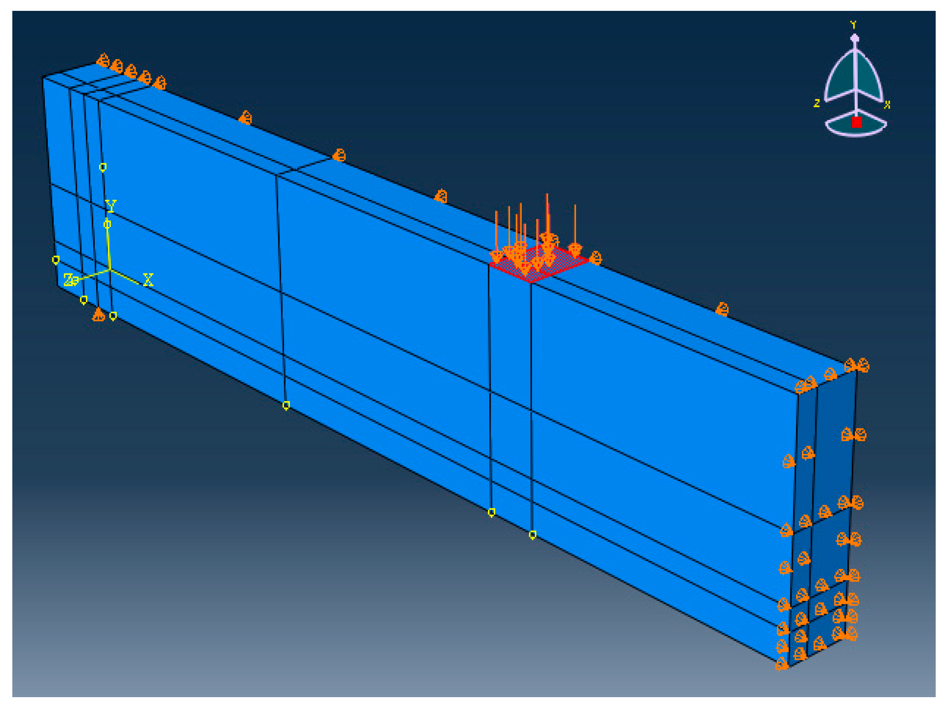
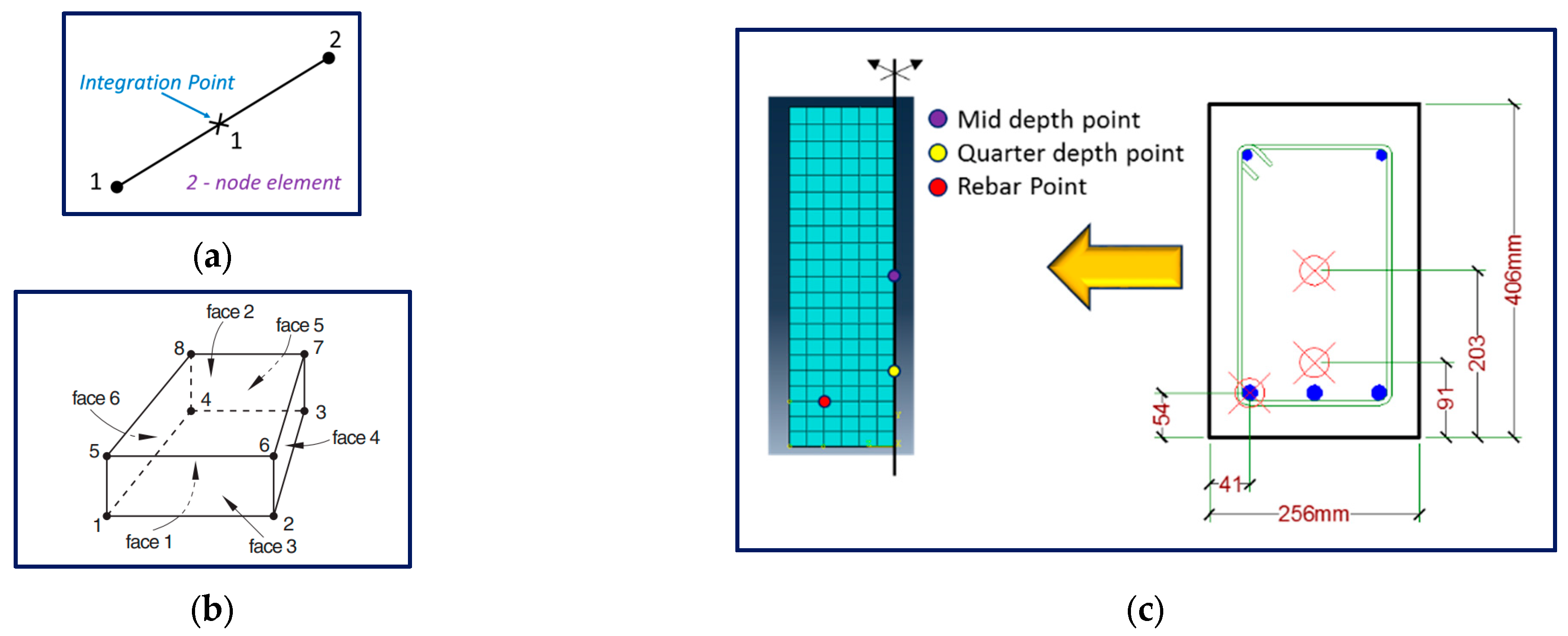
Three-dimensional coupled models were produced to perform mechanical and thermal analysis. Thus, multiple mechanical and thermal material properties were assigned nonlinearly associated with variations in the temperature. Moreover, geometry was employed with consideration of the support location, loads, reinforcements, thermal response validation points, deflection, and fire chamber limits. In addition, the thermal boundary conditions and structural boundary conditions were assigned.
2.
The first step (after the default initial step) includes the application of working loads (about 50% to 60% of ultimate capacity); on the other hand, the second step includes a different fire scenario, whether it is a standard fire or a parametric fire.
3.
The predicted thermal response obtained from the ABAQUS model results is validated against the experimental results using the pre-specified points.
4.
After the thermal response validation, the structural response is also validated by comparing the vertical deflection of the model against the experimental values. In some cases, horizontal deformation is included as well. Finally, the proposed algorithm’s effectiveness and efficiency are revealed, and the advantages of using direct coupling are highlighted.

2.3. Analysis Assumptions

The following assumptions were considered in the ABAQUS models:
a.
A full Bond (No-Slip) between concrete and reinforcement means the total strain of concrete and reinforcement are identical at the same level.
b.
The thermal properties are assumed to be reversible; in other words, material histories are ignored, such as the effect of moisture loss and other parameters.
c.
Transient creep strain is implicitly applied as per Eurocode stress–strain curves.
d.
Explosive spalling is not modeled explicitly for simplicity, as NSC shows better fire resistance than high-strength concrete (HSC) or ultra-high-performance concrete (UHPC) [6,24].

2.4. Failure Criteria

The failure criteria for RC beams during fire events depend on thermal and structural aspects. Based on thermal failure criteria and ASTM E119 [22], individual unrestrained beam classifications are established for beams from restrained and unrestrained assembly tests using the following acceptance conditions:
(a)
The maximum tension rebar temperature is 1100 °F (593 °C) during the classification period.
(b)
The beam should have a constant applied load for the whole classification period.
If the requirements mentioned above are met, the beam will achieve a specific fire endurance classification on a temperature criteria basis.
As for the strength failure criteria for the structural part, according to BS 476-20, 1987 [25], the horizontal elements are considered to fail if one of the following criteria is met:
(a)
Deflection of L/20 (in mm)
(b)
Deflection Rate of L2/9000 d (in mm/min)
Here, L is the clear span (in mm), and d is the distance from the top of the cross-section to the bottom of the tensile zone (in mm). The deflection rate is calculated every minute, beginning from the heating phase. Furthermore, the deflection limit shall not be applied for horizontal elements lower than the deflection of L/30.

2.5. Coupled Temp-Displacement Analysis

For this simulation, the DCT was used, and it involves only one model where loads and boundary conditions for thermal and structural analysis are assigned simultaneously to the coupled model, as the activated DOFs for structural and thermal are 3 and 11 DOFs, respectively.
A backward-difference scheme was used to integrate temperatures, and the system was evaluated using an approximate or exact implementation of Newton’s method for fully coupled temperature-displacement analysis, as mentioned in the ABAQUS manual [15]. Equations (1) and (2) provide the exact implementation and approximate implementation equations.
(a)
Exact implementation:
[ K u u K u θ K θ u K θ θ ] { u θ } = { R u R θ }
(b)
Approximate implementation:
[ K u u 0 0 K θ θ ] { u θ } = { R u R θ }
where u and θ are for correction to incremental displacement and temperature, respectively, and R u and R θ are the mechanical and thermal residual vectors, respectively. K i j are sub-matrices of the fully coupled Jacobian matrix. Moreover, the solution required the use of unsymmetric matrix storage. Additionally, thermal and structural equations are solved simultaneously. The exact implementation is the default technique in ABAQUS (adopted for this paper), but the approximate implementation can be performed for problems with weak coupling. In coupled temperature-displacement analysis, T3D2T and C3D8T were selected to simulate reinforcement and concrete, respectively. T3D2T is a 2-noded 3D thermally coupled truss with linear displacement and temperature. It includes three transitional DOFs (1, 2, and 3) and 11 DOFs for the temperature at the starting and ending nodes, and the same DOFs exist for the middle integration node, excluding temperature. C3D8T is an 8-node thermally coupled brick with tri-linear displacement and temperature. C3D8T has three transitional DOFs (1, 2, and 3) and 11 DOFs for the temperature at corner nodes. T3D2T and C3D8T are shown in the discussion section. C3D8T simulates concrete cracking in tension and crushing in compression. In addition, it can be used for explicit creep analysis for columns and other structural elements. Only a quarter of the beam was modeled to reduce computational effort, and symmetric boundary conditions were applied for thermal and structural analysis, as illustrated in Figure 3. The embedded constraint was used to define the interaction between concrete and reinforcing steel, which can be performed by specifying rebars as the embedded region and concrete as the host region. Fire Loads are simulated as per Eurocode [7].
The model had a constant mesh size of 25 mm; however, not every mesh size can achieve convergence within a reasonable time. As such, mesh sensitivity was not carried out in its traditional form. The appropriate mesh size was determined by strategic experimentation to manage the following constraints:
(a)
Successful numerical convergence: Excessively coarse meshing leads to premature divergence, e.g., simulation is aborted before even completing the first 30 min of fire exposure.
(b)
Practical Running Time: Excessively fine meshing leads to prohibitive computational demands, e.g., more than 24 h to simulate 10 min of fire exposure.
Such numerical limitations arise from the following:
1.
The highly nonlinear nature of the dependency on thermal and structural behaviors.
2.
The fully coupled analysis involves simultaneously running two types of interactive analyses, i.e., solving for thermal and mechanical DOFs in each sub-step, as they influence each other.
3.
The thermally induced ductile failure mechanisms of RC beams under fire loads lead to continuous crack pattern development. This significantly inhibits the successful completion of the simulation. On the other hand, the same problem will not exist in the case of vertically loaded elements, as this will only be expected just before failure due to the typical brittle failure mode for vertical elements.
As such, the mesh size was initially selected to be relatively coarse to reduce computational effort. Upon experiencing premature divergence, the mesh size was reduced, and the subsequent trial was performed until convergence.
The main advantage of using DCT over SCT is the absence of a delay time or gap between the thermal model and structural model; for SCT, thermal results must be evaluated first, and, then, the model is renamed and saved. After this, the thermal results are interpreted and checked, and elements and analysis types are transformed from thermal to structural. Besides that, thermal boundary conditions and loads are removed, thermal material properties are substituted with mechanical material properties, and, finally, structural boundary conditions and loads are applied; these procedures are generally the same as in ANSYS [8,9]. Meanwhile, direct coupling is much better and more practical, particularly for parametric studies, as it saves time and compresses all thermal and structural data into just one model, and this was concluded based on a comparison with previous simulations [8,9]. In addition, multiple errors can occur in sequential analysis procedures due to a higher tendency for misassigned data when converting thermal models to structural models. DCT does not include any converting process, and this shortcoming is completely avoided.

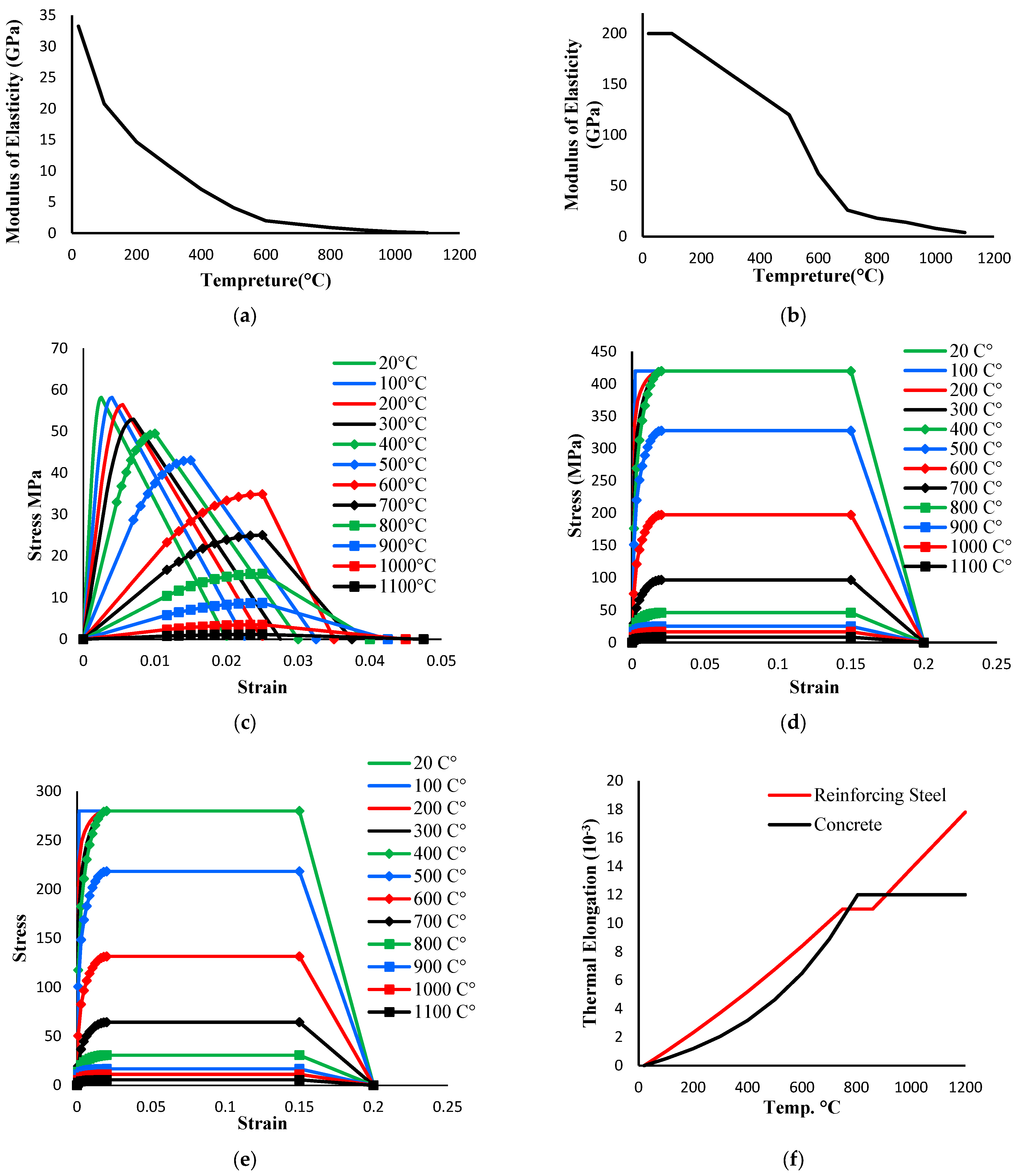
2.6. Materials Properties

2.6.1. Thermal Material Properties

The required thermal properties for thermal analysis are thermal conductivity, specific heat, and density. These properties are varied with temperature, and the governing equations for the thermal properties of concrete are defined as per Eurocode [26], as shown in Equations (3)–(11). Thermal properties for concrete are displayed in Figure 4a–c.
(a)
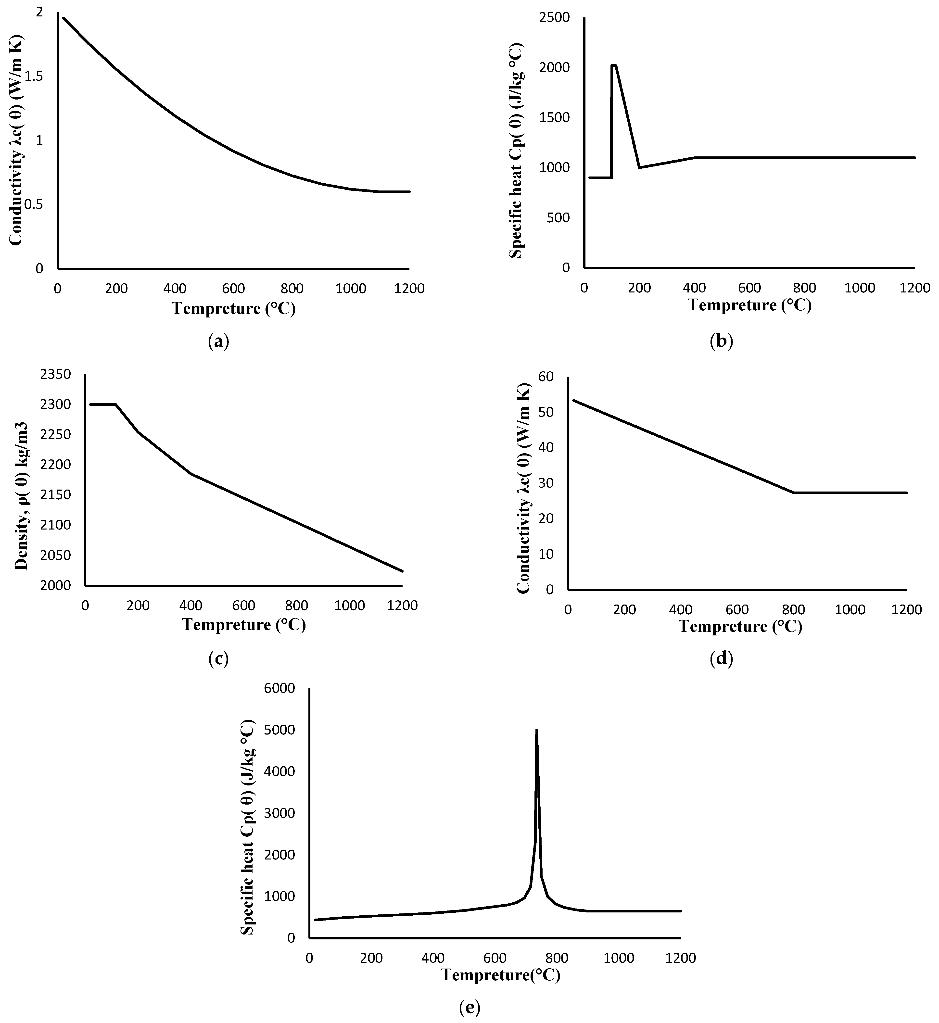
Upper limit for thermal conductivity λc(θ) (W/mK) for normal weight concrete:
λc = 2 − 0.2451 (θ/100) + 0.0107 (θ/100)2  20 °C ≤ θ ≤ 1200 °C
(b)
Specific heat cp(θ) (J/Kg K) for dry concrete (u = 0%):
cp(θ) = 900                     20 °C < θ ≤ 100 °C
cp(θ) = 900 + (θ − 100)          100 °C < θ ≤ 200 °C
cp(θ) = 1000 + (θ − 200)/2        200 °C < θ ≤ 400 °C
cp(θ) = 1100                    400 °C < θ ≤ 1200 °C
(c)
Variation in density ρc(θ) (Kg/m3) for concrete:
ρ(θ) = ρ(20 °C)                        20 °C < θ ≤ 115 °C
ρ(θ) = ρ(20 °C)*(1 − 0.02(θ − 115)/85))         115 °C < θ ≤ 200 °C
ρ(θ) = ρ(20°C)*(0.98 − 0.03(θ − 200)/200))      200 °C < θ ≤ 400 °C
ρ(θ) = ρ(20°C)*(0.95 − 0.07(θ − 400)/800))      400 °C < θ ≤ 1200 °C
Thermal properties for reinforcement are displayed in Figure 4d,e, and equations for these thermal parameters and their variation are given in Equations (12)–(17).
(a)
The thermal conductivity λa(θ) (W/mK) for structural and reinforcing steel:
λa(θ) = 54 − 3.33*10−2a                  20 °C < θ ≤ 800 °C
λa(θ) = 27.3                        800 °C < θ ≤ 1200 °C
(b)
Specific heat cp(θ) (J/Kg K) for structural and reinforcing steel:
Ca(θ) = 425 + 7.73*10−1a − 1.69*10−3a2 + 2.22*10−6a3  20 °C < θ ≤ 100 °C
Ca(θ) = 666 − (13002/(θa − 738))             100 °C < θ ≤ 735 °C
Ca(θ) = 545 − (17820/(θa − 731))             735 °C < θ ≤ 900 °C
Ca(θ) = 650                      900 °C < θ ≤ 1200 °C
(c)
Structural steel and reinforcement density ρa(θ) (Kg/m3):
ρa = 7850

2.6.2. Mechanical Material Properties

Material properties must be assigned as temperature variables to simulate the total structural response for concrete under fire load in ABAQUS. The following structural properties were assigned to temperature per Eurocode [26]: elastic modulus, stress–strain relationships, and thermal expansion coefficient. With a concrete compressive strength of 58.2 MPa, the mentioned properties are illustrated in Figure 5. The mentioned properties for rebar grades 420 MPa and 280 MPa are also displayed in Figure 5. Noting that the degradation of concrete and steel mechanical properties with time was implicitly incorporated through the shifted stress–strain curves, as described in many international codes (ACI, ASCE, Euro Code) [13,14,26]. In the case of flexural elements, the explicit implantation of transient creep strain (εtrc) is not very significant. Conversely, in the case of modeling vertical elements, the transient creep strain must be accounted for explicitly. This has been documented in many publications as researchers [27,28,29] attempted to identify when to implement transient creep strain.
Thermal elongation (thermal strain) or thermal expansion coefficient is the primary connection between thermal and structural response concerning temperature. Error in assigning these parameters will result in an incorrect structural response. Thermal elongation for reinforcing steel and concrete was obtained from thermal strain equations as per Eurocode [26], and these equations are given in Equations (18)–(22).
(a)
Thermal strain of concrete with respect to temperature:
εc(θ) = −1.2*10−4 + 6*10−6*θ + 1.4*10−113       20 °C < θ ≤ 805° C
εc(θ) = 12*10−3                805 °C < θ ≤ 1200 °C
(b)
Thermal strain for reinforcing steel with respect to temperature:
εS(θ) = −2.416*10−4 + 1.2*10−5*θ + 0.4*10−82    20 °C < θ ≤ 750 °C
εS(θ) = 11*10−3                750 °C < θ ≤ 860 °C
εS(θ) = −6.2*10−3 + 2*10−5*θ          860 °C < θ ≤ 1200 °C

3. Results, Validation, and Discussion

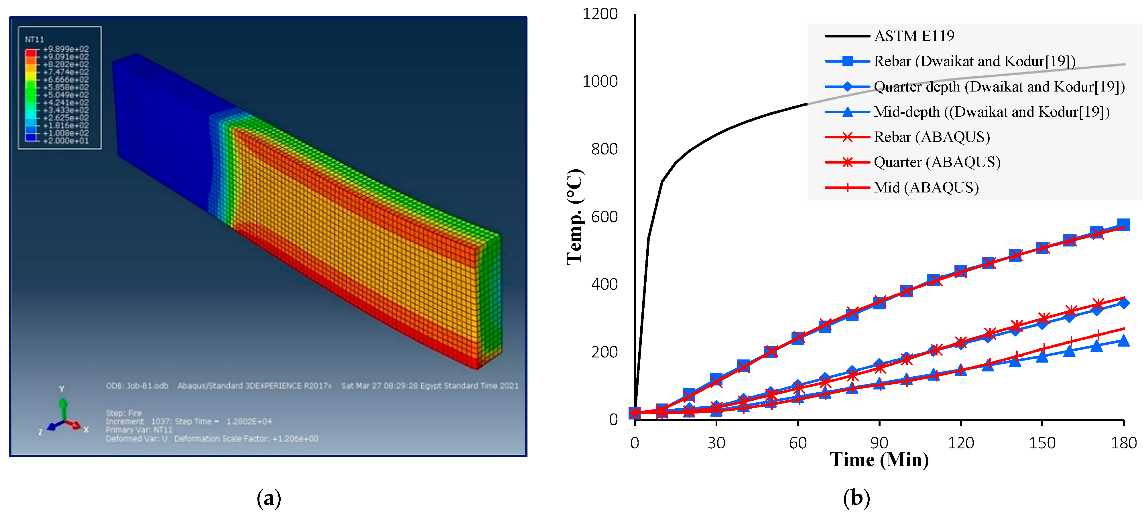
3.1. Thermal Response of B1

After the analysis, thermal and structural results were validated and studied. Three thermocouple locations in the mid-section (as shown in Table 1 and Figure 6) were used to validate the thermal results: corner tension side rebar, quarter depth, and mid-depth point. The three thermocouples used in thermal validation are not associated with the thermocouples used in the experimental work, as there are minimum required thermocouples for these tests [22]. However, the reported temperatures follow the recommended time interval. The ASTM Test Method E119 standard suggests that the temperature readings should be recorded at intervals of less than 15 min till the temperature reaches 100 °C, and, then, the temperature should be recorded more frequently (every 5 min).
To validate the ABAQUS model results, the temperature profile for B1 at failure and the temperature–time curve for the selected three points obtained from the experimental work are shown in Figure 7. As per the experimental results, the maximum reported rebar points for B1 after 180 min of ASTM E119 fire exposure were 577 °C and 570 °C, respectively. Thus, the thermal results for B1 were significantly close to the experimental results. The rebar point, quarter, and mid-point curves nearly coincide with experimental results. Moreover, the maximum rebar temperature obtained from the model is nearly the same as the experimental results, with a slight error of less than 1.3%.

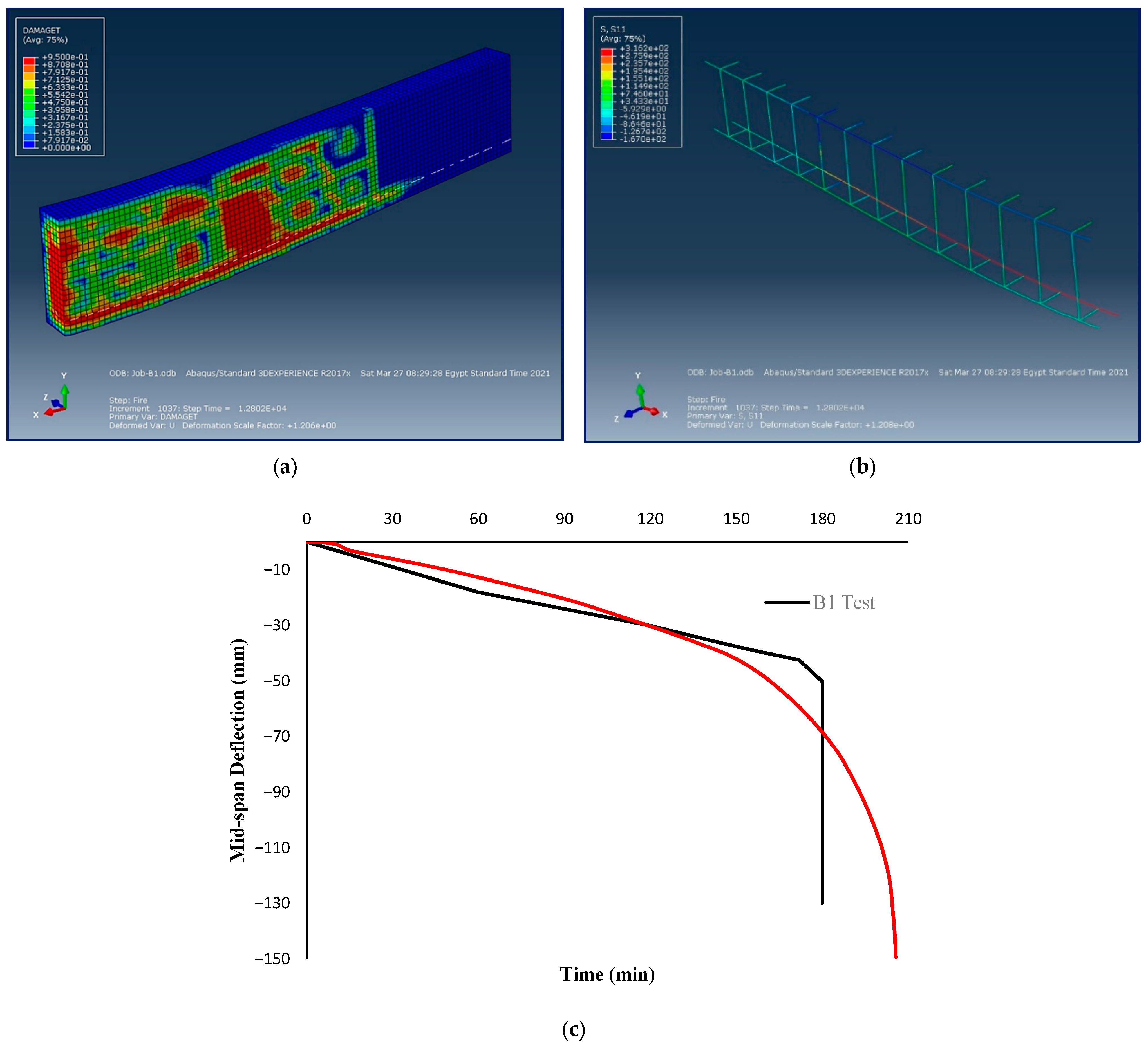
3.2. Structural Response of B1

The experimental testing determined that B1 failed after exposure to ASTM E119 for 180 min, which was considered to be the fire resistance of the beam. Using the ABAQUS model, a slightly overestimated fire resistance value of 205 min was obtained for B1. The crack pattern (tension damage) with the mid-longitudinal section view and rebar stress at failure for B1 from the ABAQUS model is shown in Figure 8. The figure shows that the fire damage propagates through the beam and does not remain on the directly exposed surfaces. Based on the rebar stress results, the corner tension rebar was found to have higher stress than the middle tension rebar. However, both the rebars have the same depth from the compression side, thus, the variance in stress is due to the higher temperature for the corner bar, depicted in Figure 7. Higher rebar temperature leads to a higher degradation of the rebar and lower yield strength. Figure 8b presents the plot for comparison between the ABAQUS models and experimental results for vertical displacement at the mid-section of B1. Moreover, regarding the failure mode, the RC beams under fire loads usually fail in an abrupt time-deformation manner in actual fire tests compared to numerical models. This is mainly attributed to the adopted assumptions in the typically used material models. In addition, we reiterate that there are still many research gaps in the literature regarding the behavior of concrete under elevated temperatures. Predicting deformations, specifically, is rather complicated, as previously illustrated in the (εtrc) dilemma discussion [27,28,29].

4. Conclusions

This paper developed and presented a proposed methodology based on a fully coupled thermal–structural nonlinear numerical model prepared using ABAQUS. The numerical model mainly aims to obtain the thermal and mechanical responses of concrete beams under mechanical loads and different fire scenarios. The experimental results were used to validate the proposed methodology and ABAQUS model. The thermal responses throughout the fire duration for B1 demonstrated excellent agreement with the experimental results. In addition, the output time deflection relationship for the B1 beam is validated with the proposed methodology. The main conclusions drawn from this study are as follows:
1.
Thermal response validity was checked for three selected thermocouple locations for the mid-section, and the models were shown to agree well with the experimental results.
2.
Structural results were checked by comparison of the vertical deflection for the entire fire duration, and it showed good agreement with the experimental data.
3.
The thermal and structural results proved the fully coupled procedures and the numerical model validity to predict the total response of RC beams under any scenario.
4.
The RC beams’ response is highly dependent on the fire temperature–time curve, as shown in the numerical model.
5.
DCT is more suitable and practical than sequential coupling, as it avoids gap time between the two models and compresses all data in only one model.
6.
DCT is also found to be more suitable than SCT because it avoids errors due to the misassigned data, model converting process, and switching boundary conditions, at which the model is transformed from the thermal to the structural model. This is in agreement with the available literature.
7.
The reinforcement at the same strain and stress as the conventional mechanical load does not produce the same result under fire load due to temperature variation. Moreover, the corner reinforcement is not equal to the middle reinforcement in temperature or yield strength, which shows that the stress for reinforcement during fire events is location dependent.
8.
This leads to the following future work recommendations:
(a)
ABAQUS can be used to study elements other than beams, such as slabs and columns, using the same proposed methodology for coupled models. Still, in the case of vertical elements, creep must be implemented explicitly.
(b)
Using DCT is a game-changer in scenarios requiring continuous interaction between thermal and structural environments. Moreover, DCT is essential in structures with large deformations, as the assumptions of conduction heat transfer analysis on an undeformed body (original geometry) will not be valid. So, DCT can be implemented in many future studies, knowing that SCT will not be practical or even applicable in the previously mentioned cases.
(c)
The explosive spalling must be considered using hydro-thermal analysis or any implicit or explicit way to enhance results. Especially for HSC and UHPC because of their low permeability, highly compact, and dense microstructure.
(d)
Transient creep strain must be considered using an explicit form, especially for vertically loaded elements such as columns and shear walls, as previously mentioned.

Author Contributions

M.E.: conceptualization, methodology, validation, writing—original draft; M.A.: resources, conceptualization, writing—review and editing, supervision. All authors have read and agreed to the published version of the manuscript.

Funding

This research was financially supported by the American University of Sharjah (AUS) through the Open Access Program (OAP).

Institutional Review Board Statement

Not applicable.

Informed Consent Statement

Not applicable.

Data Availability Statement

The data published in this paper are available from the corresponding author upon reasonable request.

Acknowledgments

This research was financially supported by the American University of Sharjah (AUS) through the Open Access Program (OAP). The authors greatly appreciate the financial support. This paper represents the opinions of the authors and does not mean to represent the position or opinions of AUS.

Conflicts of Interest

The authors declare no conflict of interest.

References

  1. Brushlinsky, N.; Ahrens, M.; Sokolov, S.V.; Wanger, P. World Fire Statistics, Report No. 25; International Association of Fire and Rescue Services: Paris, France, 2020. [Google Scholar]
  2. Ahrens, M. Reported Structure Fires by Extent of Fire Spread, Occupancy, and Loss Rates; Fire Analysis and Research Division National Fire Protection Association: Quincy, MA, USA, 2019. [Google Scholar]
  3. Choi, E.G.; Shin, Y.-S.; Kim, H.S. Structural damage evaluation of reinforced concrete beams exposed to high temperatures. J. Fire Prot. Eng. 2013, 23, 135–151. [Google Scholar] [CrossRef]
  4. Song, Y.; Fu, C.; Liang, S.; Yin, A.; Dang, L. Fire Resistance Investigation of Simple Supported RC Beams with Varying Reinforcement Configurations. Adv. Civil Eng. 2019, 2019, 8625360. [Google Scholar] [CrossRef]
  5. Xu, Y.Y.; Wu, B.; Jiang, M.; Huang, X. Experimental Study on Residual Flexural Behavior of Reinforced Concrete Beams after Exposure to Fire. AMR 2012, 457–458, 183–187. [Google Scholar] [CrossRef]
  6. Arafa, A.; Ali, H. Effect of Fire on Structural Behavior of Normal and High Strength Concrete Beams, World Academy of Science, Engineering and Technology, Open Science Index 117. Int. J. Struct. Constr. Eng. 2016, 10, 1245–1248. [Google Scholar] [CrossRef]
  7. Eurocode2. Actions on Structures, Part 1–2: General Actions—Actions on Structures Exposed to Fire; ENV 1991-1-2; European Committee for Standardization: Brussels, Belgium, 2002. [Google Scholar]
  8. Elshorbagy, M.; Abdel-Mooty, M.; Akl, A. Nonlinear Numerical Simulation of Coupled Thermal-Structural Response of RC Beams During Fire Test. In Proceedings of the 2nd International Conference on Structural Safety under Fire & Blast Loading, Brunel University, London, UK, 10–12 September 2017; pp. 392–401. [Google Scholar]
  9. Elshorbagy, M.; Abdel-Mooty, M. The coupled thermal-structural response of RC beams during fire events based on nonlinear numerical simulation. Eng. Fail. Anal. 2020, 109, 104297. [Google Scholar] [CrossRef]
  10. Bai, L.L.; Wang, Z.Q. Residual Bearing Capacity of Reinforced Concrete Member after Exposure to High Temperature. AMR 2011, 368–373, 577–581. [Google Scholar] [CrossRef]
  11. Sun, R.; Xie, B.; Perera, R.; Pan, Y. Modeling of Reinforced Concrete Beams Exposed to Fire by Using a Spectral Approach. Adv. Mater. Sci. Eng. 2018, 2018, 6936371. [Google Scholar] [CrossRef]
  12. Cai, B.; Li, B.; Fu, F. Finite element analysis and calculation method of residual flexural capacity of post-fire RC Beams. Int. J. Concr. Struct. Mater. 2020, 14, 58. [Google Scholar] [CrossRef]
  13. ACI-216-14; Code Requirements for Determining Fire Resistance of Concrete and Masonry Construction Assemblies. American Concrete Institute: Farmington Hills, MI, USA, 2014.
  14. ASCE-29-05; Standard Calculation Methods for Structural Fire Protection. American Society of Civil Engineers: Reston, VA, USA, 2007. [CrossRef]
  15. Dassault Systèmes Simulia Corp. Dassault Systemes; ABAQUS/Standard User’s Manual, Version 6.14; Dassault Systèmes Simulia Corp.: Providence, RI, USA, 2014. [Google Scholar]
  16. ANSYS Inc. ANSYS Multi-Physics Finite Element Analysis Software Version 16.0; ANSYS Inc.: Canonsburg, PA, USA, 2015. [Google Scholar]
  17. Franssen, J.M. SAFIR: A thermal-structural program for modeling structures under fire. Eng. J. 2005, 42, 143–158. [Google Scholar]
  18. Behnam, B. Simulating Post-Earthquake Fire Loading in Conventional RC Structures. In Modeling and Simulation Techniques in Structural Engineering; IGI Global: Hershey, PA, USA, 2017; pp. 425–444. [Google Scholar] [CrossRef]
  19. Franssen, J.M.; Kodur, V.; Zaharia, R. (Eds.) Designing Steel Structures for Fire Safety; CRC Press: Boca Raton, FL, USA, 2009. [Google Scholar] [CrossRef]
  20. Hajiloo, H.; Green, M.F. GFRP reinforced concrete slabs in fire: Finite element modelling. Eng. Struct. 2019, 183, 1109–1120. [Google Scholar] [CrossRef]
  21. Dwaikat, M.B.; Kodur, V.K. Response of Restrained Concrete Beams under Design Fire Exposure. J. Struct. Eng. 2009, 1408–1417. [Google Scholar] [CrossRef]
  22. ASTM Test Method E119; Standard Test Methods for Fire Tests of Building Construction and Materials. American Society for Testing and Materials: West Conshohocken, PA, USA, 2002.
  23. American Concrete Institute (ACI). Building Code Requirements for Reinforced Concrete; ACI: Detroit, MI, USA, 2008. [Google Scholar]
  24. Kodur, V.R.; Banerji, S.; Solhmirzaei, R. Effect of Temperature on Thermal Properties of Ultrahigh-Performance Concrete. J. Mater. Civil Eng. 2020, 32, 04020210. [Google Scholar] [CrossRef]
  25. BS 476-20:1987; Fire Tests on Building Materials and Structures—Part 20: Method for Determination of the Fire Resistance of Elements of Construction (General Principles). BSI: London, UK, 1987.
  26. Eurocode2. Design Concrete Structures, Part 1–2: General Rules—Structural Fire Design; ENV 1992-1-2; European Committee for Standardization: Brussels, Belgium, 2004. [Google Scholar]
  27. Alogla, S.; Kodur, V.K.R. Quantifying transient creep effects on fire response of reinforced concrete columns. Eng. Struct. 2018, 174, 885–895. [Google Scholar] [CrossRef]
  28. Kodur, V.K.R.; Alogla, S.M. Effect of high-temperature transient creep on response of reinforced concrete columns in fire. Mater. Struct. 2017, 50, 27. [Google Scholar] [CrossRef]
  29. Kodur, V.; Alogla, S.M.; Venkatachari, S. Guidance for Treatment of High-Temperature Creep in Fire Resistance Analysis of Concrete Structures. Fire Technol. 2021, 57, 1167–1197. [Google Scholar] [CrossRef]
Figure 1. Beam Configuration: (a) Elevation, (b) Cross-section, and (c) Location of thermocouples at mid-section [21].
Fire 06 00057 g001
Figure 2. (a) Sequential and (b) Direct Coupling Technique.
Fire 06 00057 g002
Figure 3. Structural boundary conditions.
Fire 06 00057 g003
Figure 4. Thermal properties versus temperature: (a) Thermal conductivity (upper limit) of concrete, (b) Specific heat of concrete, (c) Density of concrete, (d) Steel conductivity, and (e) Specific heat of steel [26].
Fire 06 00057 g004
Figure 5. Mechanical properties for elevated temperatures: (a) Modulus of elasticity of concrete (N/mm2), (b) Modulus of elasticity of steel (N/mm2), (c) Stress–strain relationship, (d) Longitudinal rebar stress–strain relationship, (e) Stirrup stress–strain relationship, and (f) Thermal elongation.
Fire 06 00057 g005
Figure 6. (a) T3D2T (2-node element) Direct Coupled Element [17], (b) C3D8T (8-node element) Direct Coupled Element [17], and (c) Points used for thermal validation.
Fire 06 00057 g006
Figure 7. B1 Thermal Response: (a) Temperature profile at failure, and (b) Predicted and measured cross-sectional temperatures.
Fire 06 00057 g007
Figure 8. B1 Structural response: (a) failure crack pattern, (b) reinforcement stress failure, and (c) mid-span vertical displacement.
Fire 06 00057 g008
Table 1. Points for thermal response validation.
Point NameXY
Mid-depth point128203
Quarter depth point12891
Rebar Point4154
Disclaimer/Publisher’s Note: The statements, opinions and data contained in all publications are solely those of the individual author(s) and contributor(s) and not of MDPI and/or the editor(s). MDPI and/or the editor(s) disclaim responsibility for any injury to people or property resulting from any ideas, methods, instructions or products referred to in the content.

