
Study of Atmospheric Plasma-Based Mass Separation System for High-Level Radioactive Waste Treatment

Abstract
:Highlights
- High-level radioactive waste management.
- Plasma-based mass separation process design.
- Functional modelling of a mass separation system.
- Multiphysics simulation of plasma for a generic mass separation system in COMSOL.
1. Introduction
2. Plasma-Based Mass Separation
2.1. Mass Separation Experiments
2.2. Plasma-Based Mass Separation for High-Level Nuclear Waste Remediation
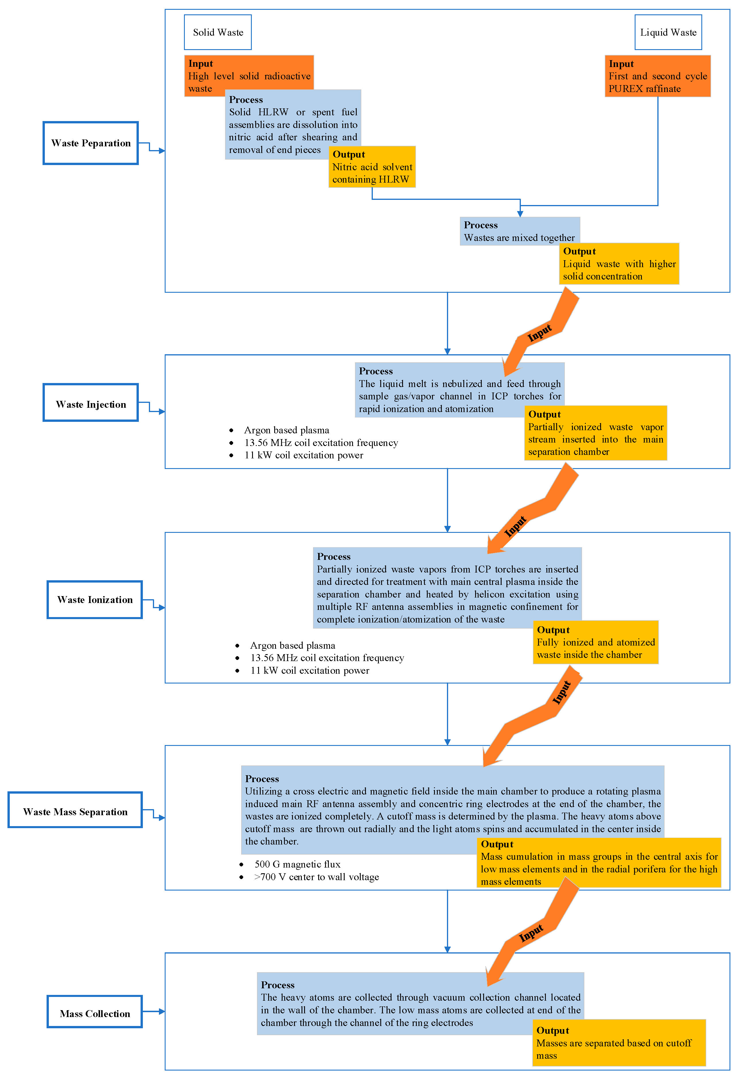
3. Functional Modelling of a Generic Plasma-Based Mass HLRW Separation System
3.1. Waste Preparation
3.2. Waste Injection
3.3. Waste Ionization
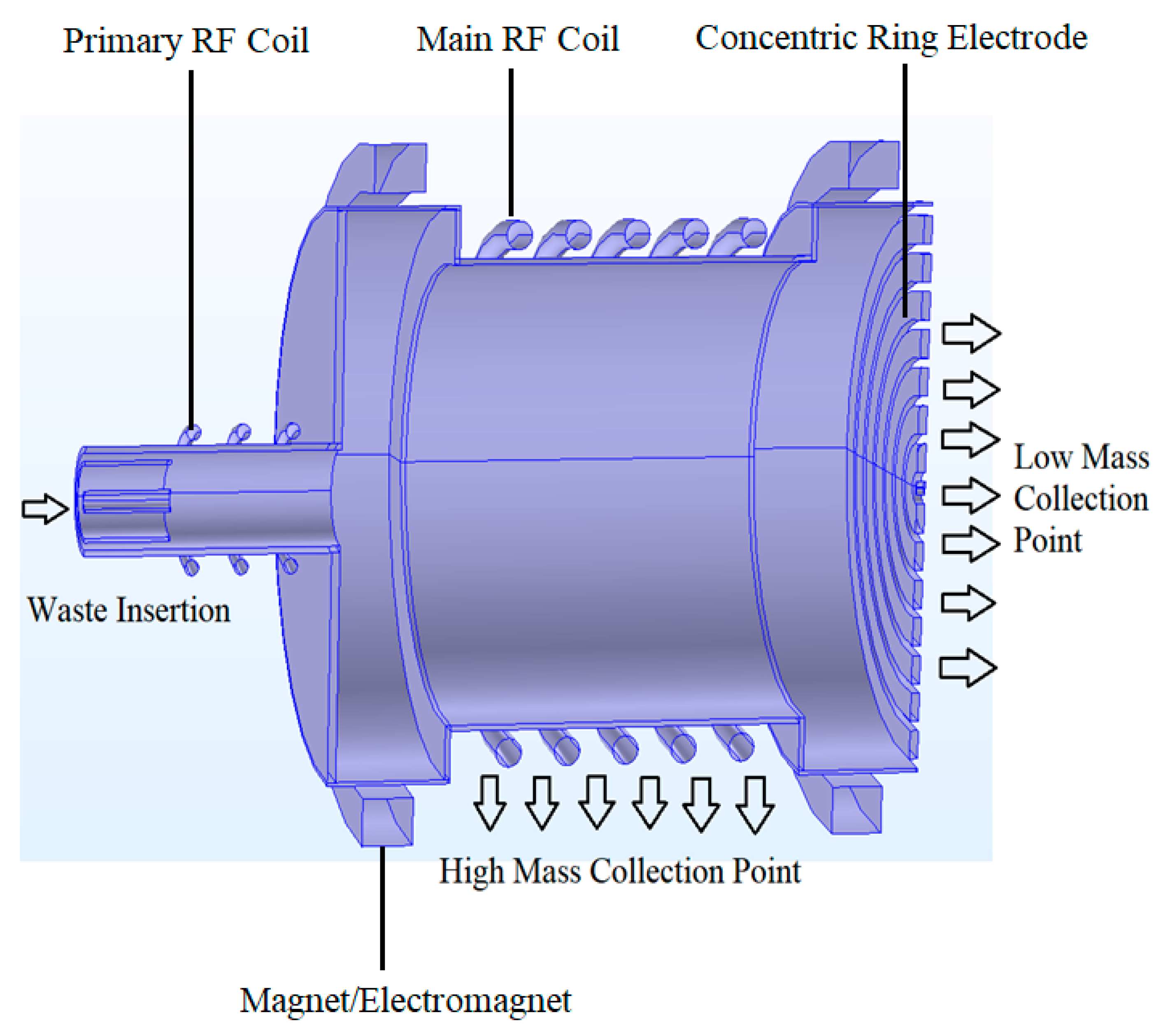
3.4. Waste Mass Separation
3.5. Mass Collection
4. Mass Separation Simulation of ICP for Noble Gas inside Mass Separation Unit
- The plasma is fully ionized (a mixture of electrons and ions).
- The plasma optically thin is under local thermodynamic equilibrium (LTE) conditions.
- The plasma is considered a locally neutral Newtonian fluid mixture.
- The plasma flow is laminar and quasi-incompressible under atmospheric pressure.
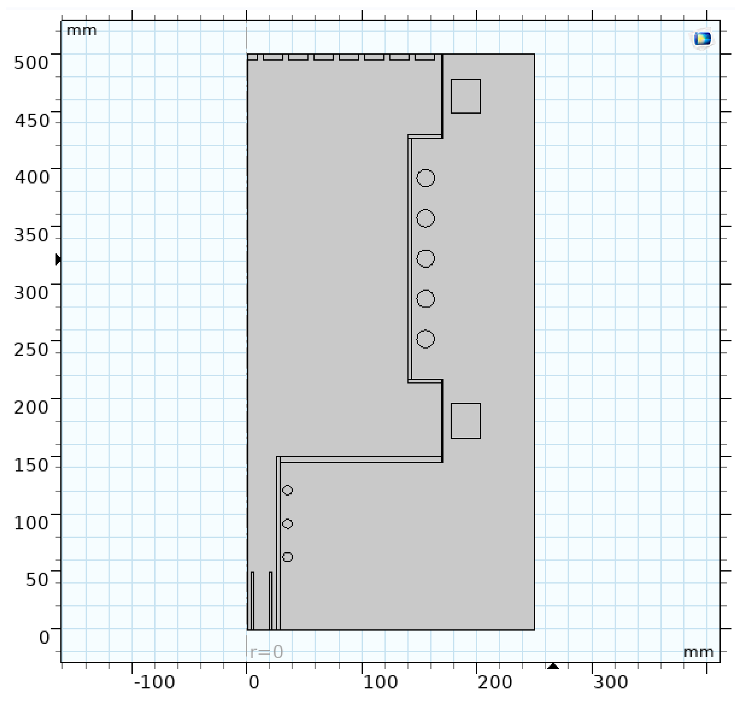
4.1. Mathematical and Physical Model
- Resistive heating (ohmic heating):
- Volumetric net radiation loss Qrad is defined by the total volumetric emission coefficient, which is a material property.
- Enthalpy transport (energy carried by the electric current):
4.2. Results and Discussion
5. Conclusions
Author Contributions
Funding
Institutional Review Board Statement
Informed Consent Statement
Data Availability Statement
Acknowledgments
Conflicts of Interest
References
- International Atomic Energy Agency. Status and Trends in Spent Fuel and Radioactive Waste Management. In IAEA Nuclear Energy Series NW-T-1.14; STI/PUB/1799; IAEA: Vienna, Austria, 2018. [Google Scholar]
- Jeffs, E. A Nuclear Energy Revival. In Green Energy: Sustainable Electricity Supply with Low Environmental Impact, 1st ed.; CRC Press: Boca Raton, FL, USA, 2009; p. 83. [Google Scholar]
- World Nuclear Association. Storage and Disposal Options for Radioactive Waste; World Nuclear Association: London, UK, 2020. [Google Scholar]
- Council, N.R. Disposition of High-Level Radioactive Waste through Geological Isolation: Development, Current Status, and Technical and Policy Challenges; The National Academies Press: Washington, DC, USA, 1999. [Google Scholar] [CrossRef]
- Nechaev, A.; Onufriev, V.; Thomas, K.T. Long-Term Storage and Disposal of Spent Fuel; IAEA: Vienna, Austria, 1986. [Google Scholar]
- International Atomic Energy Agency. Long Term Storage of Spent Nuclear Fuel-Survey and Recommendations; IAEA TECDOC-1293: Vienna, Austria, 1994. [Google Scholar]
- Wald, M.L. A Safer Nuclear Crypt. The New York Times. 5 July 2011. Available online: https://www.nytimes.com/2011/07/06/business/energy-environment/06cask.html (accessed on 4 February 2023).
- U.S.NRC. Cask Storage For Spent Fuel, Engineering News-Record. Available online: https://www.enr.com/articles/3479-cask-storage-for-spent-fuel (accessed on 4 February 2023).
- Fetterman, A.J.; Fisch, N.J.; Based, S.; Ion, E.; Diagnostic, L. Plasma Mass Filters for Nuclear Waste Reprocessing; USDOE Office of Science: Princeton, NJ, USA, 2011.
- Miguirditchian, M.; Vanel, V.; Marie, C.; Pacary, V.; Charbonnel, M.C.; Berthon, L.; Hérès, X.; Montuir, M.; Sorel, C.; Bollesteros, M.J.; et al. Poinssot, Americium Recovery from Highly Active PUREX Raffinate by Solvent Extraction: The EXAm Process. A Review of 10 Years of R&D. Solvent Extr. Ion Exchang. 2020, 38, 365–387. [Google Scholar] [CrossRef]
- Peiman, W.; Pioro, I.L.; Gabriel, K.; Hosseiny, M. Thermal aspects of conventional and alternative fuels. In Handbook of Generation IV Nuclear Reactors; Woodhead Publishing: Sawston, UK, 2016; pp. 583–635. [Google Scholar] [CrossRef]
- Ohkawa, T.; Miller, R.L. Band gap ion mass filter. Phys. Plasmas 2002, 9, 5116–5120. [Google Scholar] [CrossRef]
- Smith, L.P.; Parkins, W.E.; Forrester, A.T. On the Separation of Isotopes in Quantity by Electromagnetic Means. Phys. Rev. 1947, 72, 989. [Google Scholar] [CrossRef]
- Parkins, W.E. The Uranium Bomb, the Calutron, and the Space-Charge Problem. Phys. Today 2005, 58, 45–51. [Google Scholar] [CrossRef]
- Bonnevier, B. Experimental evidence of element and isotope separation in a rotating plasma. Plasma Phys. 1971, 13, 763. [Google Scholar] [CrossRef]
- Krishnan, M.; Geva, M.; Hirshfield, J.L. Plasma Centrifuge. Phys. Rev. Lett. 1981, 46, 36. [Google Scholar] [CrossRef]
- Evans, P.J.; Paoloni, F.J.; Noorman, J.T.; Whichello, J.V. Measurements of mass separation in a vacuum arc centrifuge. J. Appl. Phys. 1989, 66, 115–118. [Google Scholar] [CrossRef]
- del Bosco, E.; Dallaqua, R.S.; Ludwig, G.O.; Bittencourt, J.A. Isotopic enrichment in a plasma centrifuge. J. Appl. Phys. 1998, 50, 1716. [Google Scholar] [CrossRef]
- Zweben, S.J.; Gueroult, R.; Fisch, N.J. Plasma mass separation. Phys. Plasmas 2018, 25, 90901. [Google Scholar] [CrossRef]
- Freeman, R.; Agnew, S.; Anderegg, F.; Cluggish, B.; Gilleland, J.; Isler, R.; Litvak, A.; Miller, R.; O’Neill, R.; Ohkawa, T.; et al. Archimedes Plasma Mass; FilterConf Proc. 694; AIP Publishing: Moran, WY, USA, 2003; p. 403. [Google Scholar] [CrossRef]
- Ahlfeld, C.E.; Wagoner, J.D.; Sevier, D.L.; Freeman, R.L. Application, design and project implementation of a plasma mass separator for enhanced high level waste processing. In Proceedings of the Symposium on Fusion Engineering, Tokyo, Japan, 22–27 May 2005. [Google Scholar] [CrossRef]
- Cluggish, B.P.; Anderegg, F.A.; Freeman, R.L.; Gilleland, J.; Hilsabeck, T.J.; Isler, R.C.; Lee, W.D.; Litvak, A.A.; Miller, R.L.; Ohkawa, T.; et al. Density profile control in a large diameter, helicon plasma. Phys. Plasmas 2005, 12, 057101. [Google Scholar] [CrossRef]
- Paperny, V.L.; Krasov, V.I.; Lebedev, N.V.; Astrakchantsev, N.V.; Chernikch, A.A. Vacuum arc plasma mass separator. Plasma Sources Sci. Technol. 2014, 24, 015009. [Google Scholar] [CrossRef]
- Gueroult, R.; Evans, E.S.; Zweben, S.J.; Fisch, N.J.; Levinton, F. Initial experimental test of a helicon plasma based mass filter. Plasma Sources Sci. Technol. 2016, 25, 035024. [Google Scholar] [CrossRef]
- Smirnov, V.P.; Samokhin, A.A.; Vorona, N.A.; Gavrikov, A.V. Study of charged particle motion in fields of different configurations for developing the concept of plasma separation of spent nuclear fuel. Plasma Phys. Rep. 2013, 39, 456–466. [Google Scholar] [CrossRef]
- Aruquipa, W.; Velasquez, C.E.; De, G.; Barros, P.; Pereira, C.; Auxiliadora, M.; Veloso, F.; Costa, A.L. Reprocessing Techniques of Lwr Spent Fuel for Reutilization in Hybrid Systems and Iv Generation Reactors. In Proceedings of the 2017 International Nuclear Atlantic Conference—INAC 2017, Belo Horizonte, Brazil, 22–27 October 2017. [Google Scholar]
- Choppin, G.; Rydberg, J.; Liljenzin, J.-O. Radiochemistry and Nuclear Chemistry (Google eBook); Butterworth-Heinemann: Oxford, UK, 2001; Available online: https://books.google.com/books/about/Radiochemistry_and_Nuclear_Chemistry.html?id=iH-ty5d92ZQC (accessed on 9 December 2021).
- Rodríguez-Penalonga, L.; Soria, B.Y.M. A review of the nuclear fuel cycle strategies and the spent nuclear fuel management technologies. Energies 2017, 10, 1235. [Google Scholar] [CrossRef]
- IAEA. Nuclear Energy Series No. NF-T-3.5: Costing of Spent Nuclear Fuel Storage; IAEA: Vienna, Austria, 2009; Available online: http://www.iaea.org/Publications/index.html (accessed on 12 December 2021).
- C. Budget Office. CBO TESTIMONY Statement of Peter R. Orszag Director. In Costs of Reprocessing Versus Directly Disposing of Spent Nuclear Fuel: Before the Committee on Energy and Natural Resources United States Senate; C. Budget Office: Washington, DC, USA, 2007. [Google Scholar]
- Bunn, M.; Fetter, S.; Holdren, J.P.; van der Zwaan, B. The Economics of Reprocessing versus Direct Disposal of Spent Nuclear Fuel. Nucl. Technol. 2003, 150, 209–230. [Google Scholar] [CrossRef]
- OECD Nuclear Energy Agency. The Cost of High-Level Waste Disposal in Geological Repositories: An Analysis of Factors Affecting Cost Estimates; Nuclear Energy Agency: Paris, France, 1993; p. 147. Available online: https://www.oecd-nea.org/jcms/pl_13006/cost-of-high-level-waste-disposal-in-geological-repositories-the?details=true (accessed on 12 December 2021).
- IAEA. TECDOC No. 1587: Spent Fuel Reprocessing Options; IAEA: Vienna, Austria, 2009. [Google Scholar]
- Ontario Power Generation. New Brunswick Power, Hydro-Québec, and Atomic Energy of Canada Limited, Cost Estimate for a Deep Geologic Repository for Used Nuclear Fuel; Ontario Power Generation: Toronto, ON, Canada, 2003. [Google Scholar]
- Hamida, S.B.; Grandou, A.; Jankovic, M.; Eckert, C.; Huet, A.; Bocquer, J.C. A Comparative Case Study of Functional Models to Support System Architecture Design. Procedia Comput. Sci. 2015, 44, 325–335. [Google Scholar] [CrossRef]
- Gabbar, H.A.; Darda, S.A.; Damideh, V.; Hassen, I.; Aboughaly, M.; Lisi, D. Comparative study of atmospheric pressure DC, RF, and microwave thermal plasma torches for waste to energy applications. Sustain. Energy Technol. Assess. 2021, 47, 101447. [Google Scholar] [CrossRef]
- Sarra-Bournet, C.; Turgeon, S.; Mantovani, D.; Laroche, G. Comparison of atmospheric-pressure plasma versus low-pressure RF plasma for surface functionalization of PTFE for biomedical applications. Plasma Process. Polym. 2006, 3, 506–515. [Google Scholar] [CrossRef]
- Thomas, S.N. Mass spectrometry, In Contemporary Practice in Clinical Chemistry; Academic Press: Cambridge, MA, USA, 2019; pp. 171–185. [Google Scholar] [CrossRef]
- Ashcroft, N.W.; Mermin, N.D. Solid State Physics. Available online: https://www.scirp.org/(S(vtj3fa45qm1ean45vvffcz55))/reference/ReferencesPapers.aspx?ReferenceID=1476522 (accessed on 14 July 2022).
- COMSOL Multiphysics, Inductively Coupled Plasma (ICP) Torch. 2022. Available online: https://www.comsol.com/model/inductively-coupled-plasma-icp-torch-18125 (accessed on 2 January 2020).
- Jonkers, J.; Van De Sande, M.; Sola, A.; Gamero, A.; Van Der Mullen, J. On the differences between ionizing helium and argon plasmas at atmospheric pressure. Plasma Sources Sci. Technol. 2003, 12, 30–38. [Google Scholar] [CrossRef]
- Bahouh, H.; Rebiai, S.; Rochette, D.; Vacher, D.; Dudeck, M. Modelling of an inductively coupled plasma torch with argon at atmospheric pressure. Phys. Scr. 2014, 2014, 014008. [Google Scholar] [CrossRef]
- Lei, F.; Li, X.; Liu, D.; Liu, Y.; Zhang, S. Simulation study of an inductively coupled plasma discharge with different copper coil designs and gas compositions. AIP Adv. 2019, 9, 085228. [Google Scholar] [CrossRef]


| Devices (Location) | Working Species | Year(s) |
|---|---|---|
| Calutron (Berkley, ORNL) | U isotopes | 1941–1998 |
| FI torus (Sweden) | H/Ar | 1966–1971 |
| ICRH (US, Russia, France) | Many isotopes/elements | 1976–present |
| Plasma centrifuge (Yale) | Metal isotopes and elements | 1980–1987 |
| Vacuum arc centrifuge (Australia) | Cu/Zn and their isotopes | 1989–1999 |
| Vacuum arc centrifuge (Brazil) | C, Al, Mg, Zn, Cd, Pb, etc. | 1987–1998 |
| Archimedes filter (San Diego) | Xe/Ar and Cu/Ag/Au? | 1998–2005 |
| Linear device with electrodes (Kyushu) | Ar and Xe | 2007 |
| POMS-E-3 (Irkutsk) | N, Ar, and Kr | 2010–present |
| Vacuum arc separator (Irkutsk) | Ni, Cr, Fe, and W | 2011–2015 |
| PMFX (PPPL) Ar/Kr 2013–2014 | Ar/Kr | 2013–1014 |
| SNF separator (JIHT Moscow) | U, Gd, and He | 2013–present |
| Application | Cutoff Mass (amu) |
|---|---|
| Spent fuel rod | ~200 |
| HLW from reprocessing | ~80 |
| Method | Unit | USD | Cost Breakdown | |
|---|---|---|---|---|
| Reprocessing | THORP and UP-3 | USD/kgHM | 1760 | ~6 B USD capital cost, 10 years of operation with 800 tHM/y processing capability, refurbishment and decommissioning 30% capital cost |
| Government-owned | USD/kgHM | 1350 | 30 years operation period | |
| Privately owned | USD/kgHM | 2000 | 30 years operation period and guaranteed rate of return | |
| Dry cask interim storage | On-site | USD/kgHM | 110–130 | 1000 tonnes facility, 40 years lifetime. 10 M USD capital cost |
| Off-site | USD/kgHM | 210–275 | ||
| MOX fuel fabrication | USD/kgHM | 1500 | Recovered plutonium oxide mixing with uranium oxide | |
| Deep Geological Repository * | CANDU | USD/KgHM | 100 | 3.6 M USD fuel bundle, 2.5 B USD capital and 7 B USD, in 30 years of operation and closure |
| LWR | USD/KgHM | 400 | 30 years of operation and closure |
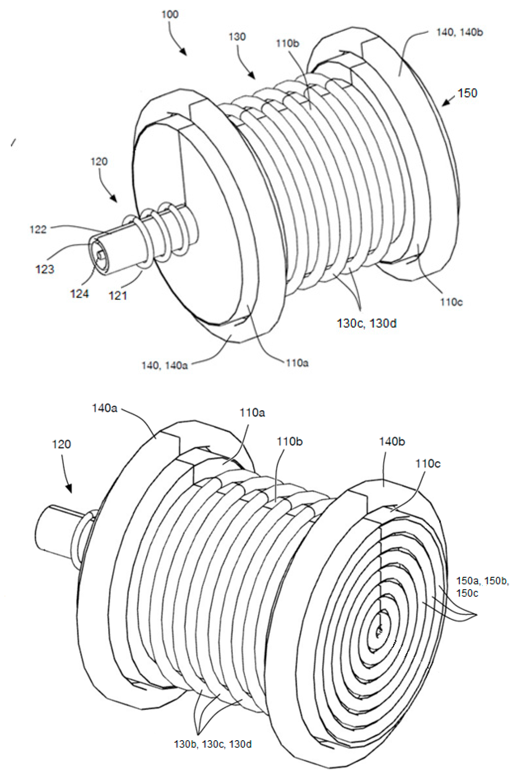
| Components | Details |
|---|---|
| 100 | Mass separation system |
| 110 (110a, 110b, 110c) | Separation apparatus |
| 120 (121, 122, 123, 124) | Primary RF ICP torch (RF coils, sheath wall, central wall, carrier wall) |
| 130 (130b, 130c, 130d) | Main RF ICP torch (RF coils) |
| 140 (140a, 140b) | Electromagnets (coils) |
| 150 (150a, 150b, 150c) | End electrodes (concentric rings) |
| Parameter | Value |
|---|---|
| (axial length) | 0.35 m |
| a (radial width) | 0.14 m |
| Magnet | electromagnet |
| Gas velocity | 0.1–0.13 m/s |
| (magnetic field) | 0.02–0.037 T |
| (RF power) | 11 kW |
| Z (ion charge) | 1 |
| Voltage | ≤20–25 V |
| Current (kA) | Magnetic Field (T) | Cutoff Point (amu) |
|---|---|---|
| 2.5 | 0.0253 | 5.97~6 |
| 3 | 0.314 | 9 |
| 3.5 | 0.0358 | 12 |
| Simulation | RF Power | Magnetic Field (T) | Electric Field | Comments | |
|---|---|---|---|---|---|
| Argon ICP | Helium ICP | ||||
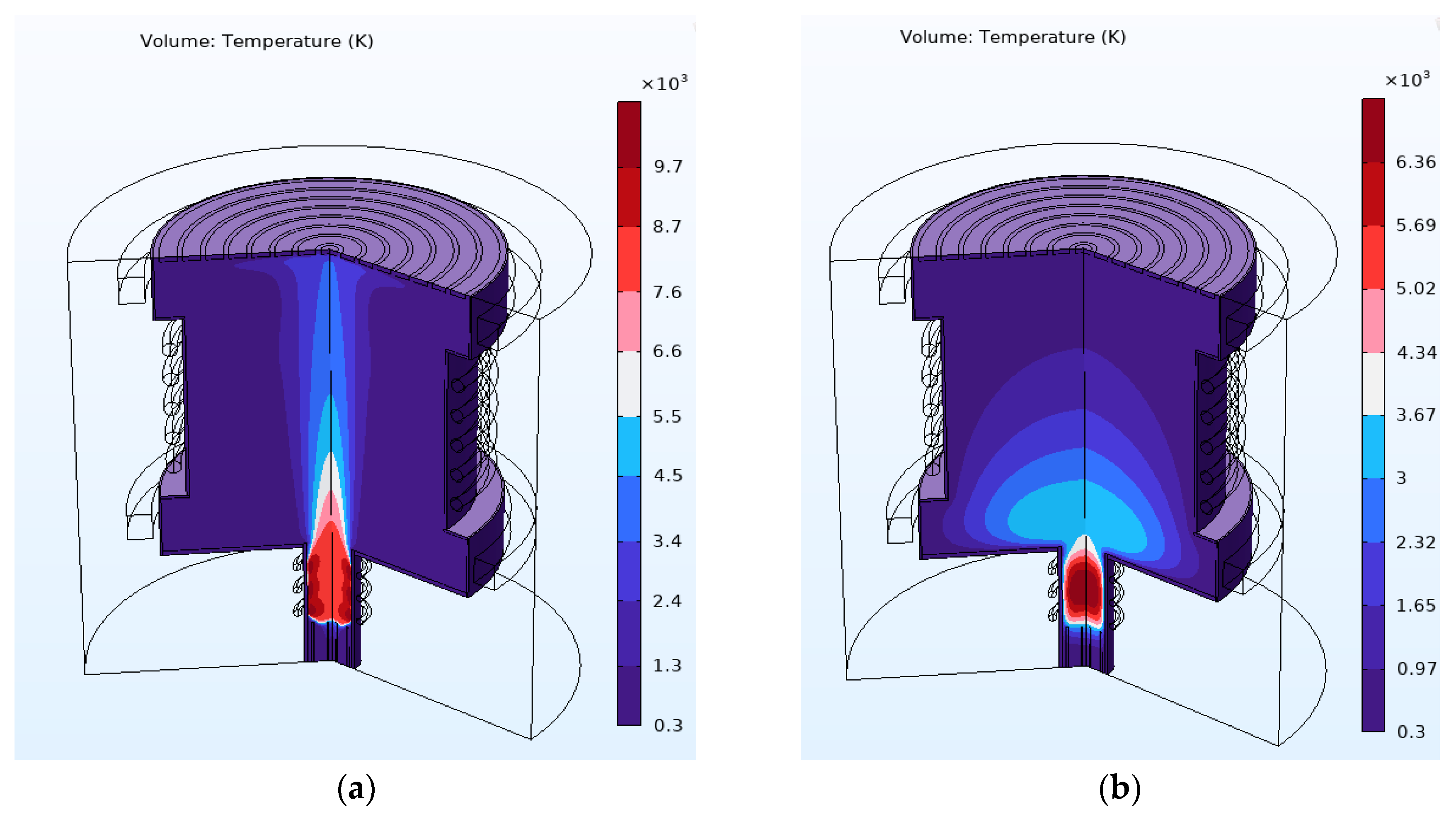
| Primary RF ICP | 11 kW | T > 10,000 K | T > 6500 K | ||
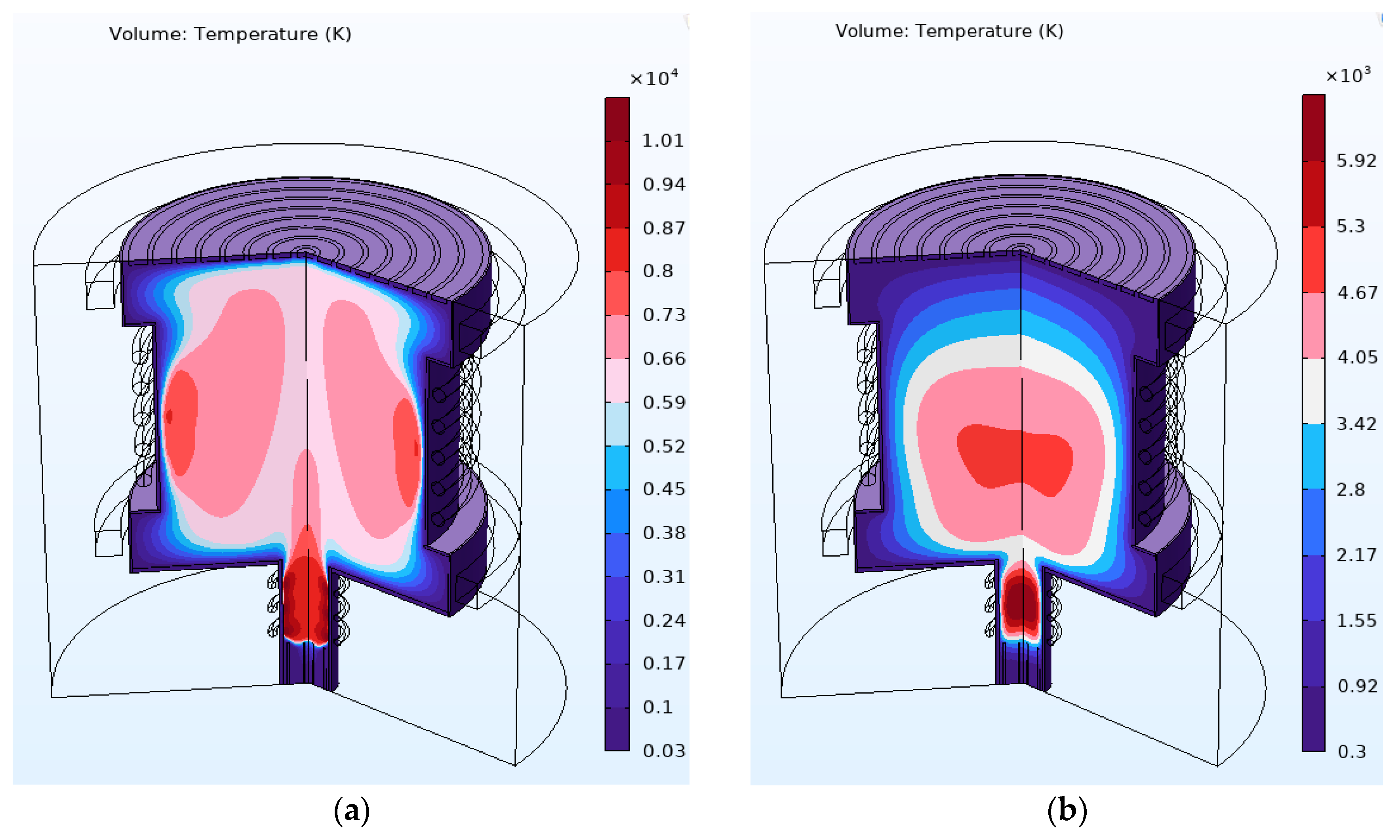
| Primary RF and main RF ICP | 11 kW | Average T > 6000 K inside the chamber | Average T > 4000 K inside the chamber | ||
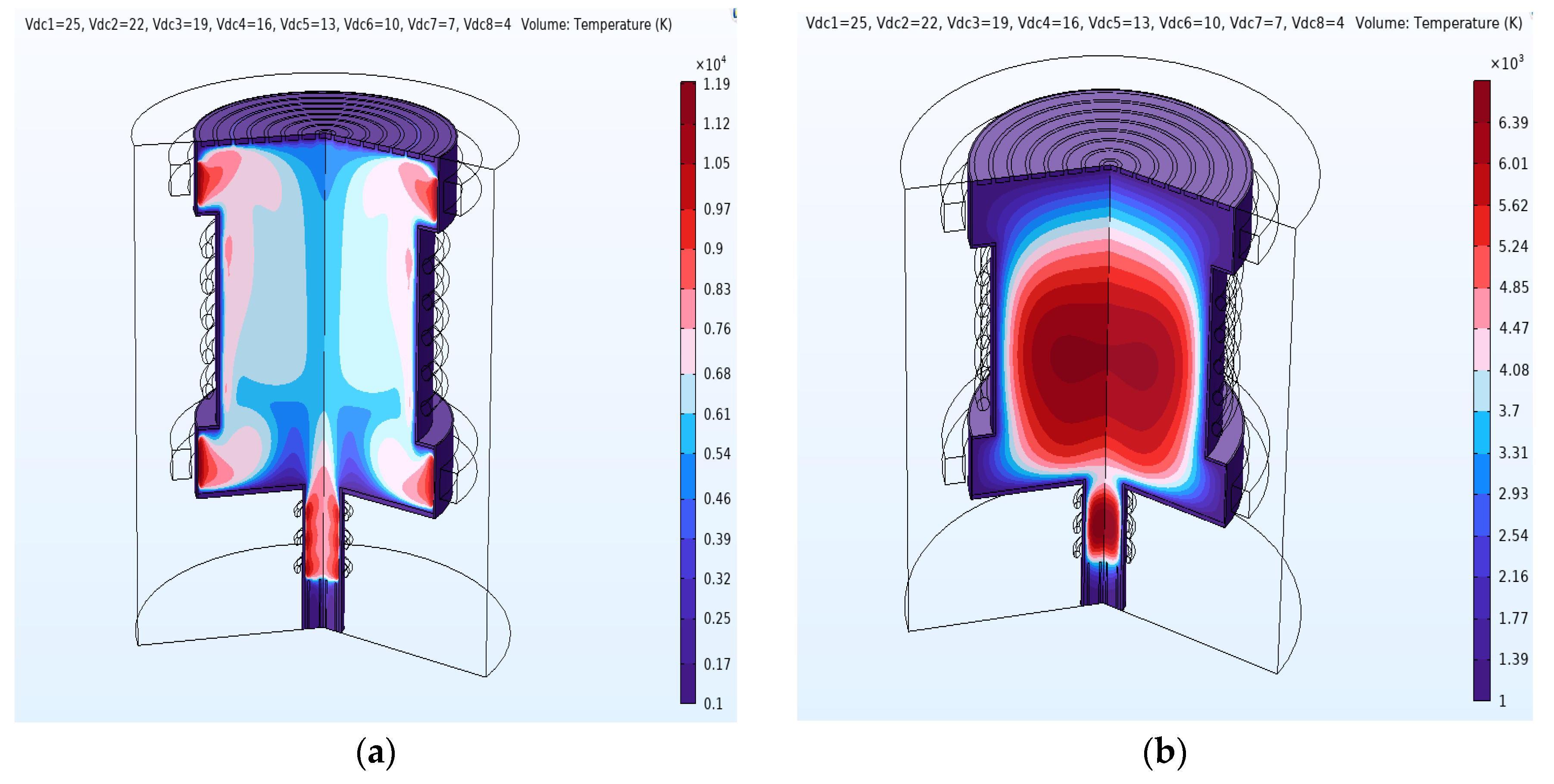
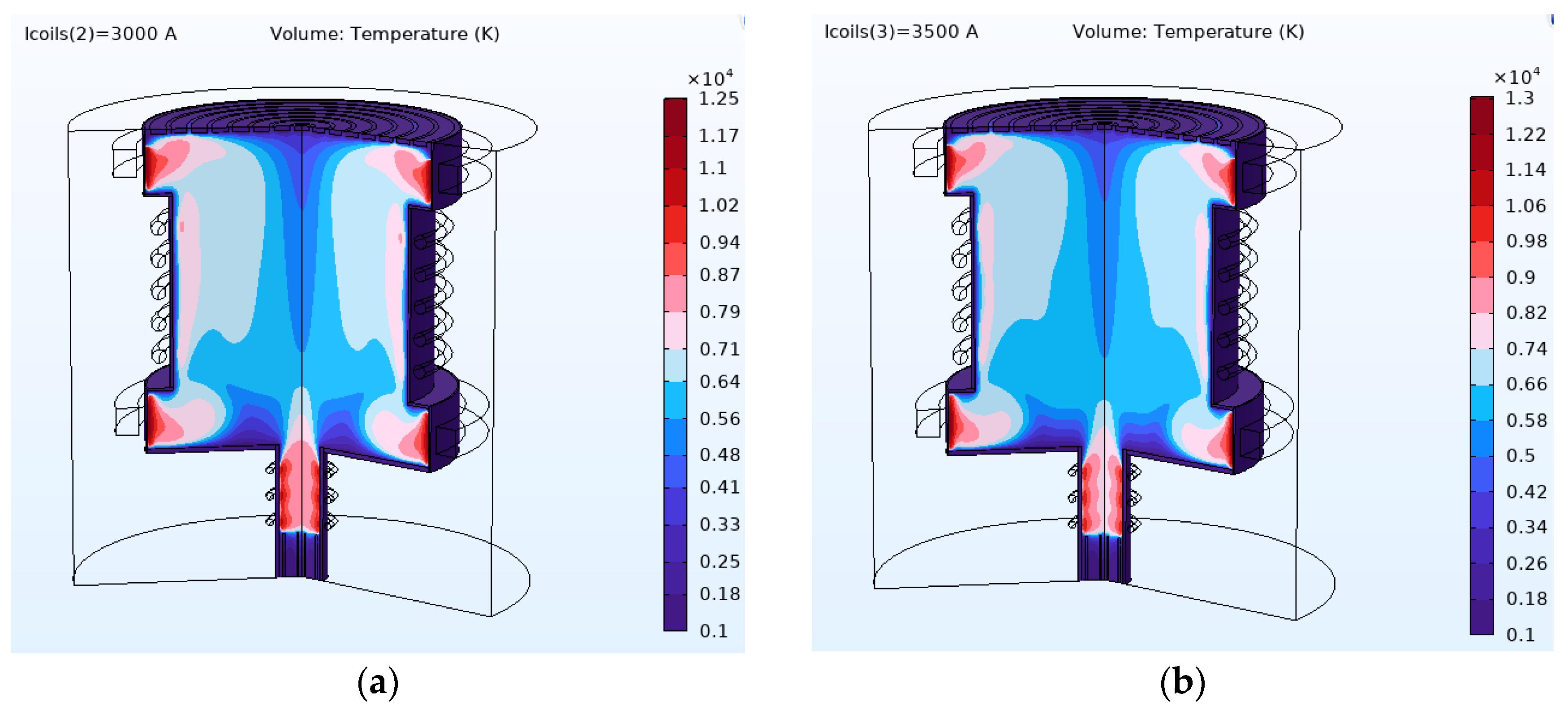
| Mass separation condition | 11 kW | 0.0253 G, 0.0314 G, and 0.0358 G | Maximum 25 V to the centermost ring | Hottest plasma region close to the radial wall | Hottest plasma region at the center |
Disclaimer/Publisher’s Note: The statements, opinions and data contained in all publications are solely those of the individual author(s) and contributor(s) and not of MDPI and/or the editor(s). MDPI and/or the editor(s) disclaim responsibility for any injury to people or property resulting from any ideas, methods, instructions or products referred to in the content. |
© 2023 by the authors. Licensee MDPI, Basel, Switzerland. This article is an open access article distributed under the terms and conditions of the Creative Commons Attribution (CC BY) license (https://creativecommons.org/licenses/by/4.0/).
Share and Cite
Abu Darda, S.; Gabbar, H.A. Study of Atmospheric Plasma-Based Mass Separation System for High-Level Radioactive Waste Treatment. Plasma 2023, 6, 592-610. https://doi.org/10.3390/plasma6030041
Abu Darda S, Gabbar HA. Study of Atmospheric Plasma-Based Mass Separation System for High-Level Radioactive Waste Treatment. Plasma. 2023; 6(3):592-610. https://doi.org/10.3390/plasma6030041
Chicago/Turabian StyleAbu Darda, Sharif, and Hossam A. Gabbar. 2023. "Study of Atmospheric Plasma-Based Mass Separation System for High-Level Radioactive Waste Treatment" Plasma 6, no. 3: 592-610. https://doi.org/10.3390/plasma6030041