1. Introduction
The basic solution for the divertor targets of ITER and DEMO tokamak is a monoblock design consisting of a tungsten (W) armor shell, an intermediate copper layer, and cooler channels made of CuCrZr [
1,
2]. A lifetime of such components is affected by erosion, thermal fatigue, and damage due to high neutron flux. Furthermore, it has been shown that the melting of monoblock edges is almost inevitable, and the margin for heat load mitigation is extremely small [
3]. In this regard, liquid metals have become promising alternatives for the material of tokamak plasma-facing components (PFCs) [
4,
5,
6]. Their main advantages are the self-healing (replenishment) of the plasma-facing surfaces and their lower sensitivity to neutron damage. As a result, the lifetime of liquid metal PFCs could be significantly increased compared to conventional solid solutions.
The main liquid metals considered for the PFC are lithium (Li) and tin (Sn). Li is a material with a low nuclear charge (Z = 3); therefore, Li radiation losses in the core plasma are negligible. However, the Li operational window is rather narrow as it is necessary to maintain the Li surface temperature below 700
C–800
C [
7] in order to avoid strong evaporation. On the contrary, Sn is an element with a high nuclear charge (Z = 50) that can significantly enhance the radiation losses in the entire plasma volume. Nevertheless, Sn benefits from a wider operational window since low evaporation is maintained up to temperatures of 1200
C–1300
C [
7].
An additional feature of liquid metals is the heat flux mitigation due to the so-called vapor shielding effect [
8]. Vapor shielding is also observed for solid materials, but unlike liquid metals, melting and evaporation of the solid target surface leads to irreversible damage and degradation of its properties. It is assumed that in the case of Sn, the vapor shielding will not play a significant role during a steady state operation due to the high surface temperature required (nevertheless, shielding will help protect Sn targets from transients, such as disruptions and type I ELMs). On the contrary, Li can significantly increase PFC resistance to extreme heat loads due to this effect [
8]. In what follows, we consider the option of liquid lithium (LL) PFC exclusively, since in a steady state, the behavior that Sn targets is virtually identical to the solid targets.
Conceptually, all of the proposed designs of the LL-covered PFCs aimed to protect the substrate from erosion caused by the heat and particle fluxes can be divided into two types. The first type is the limiter or divertor PFC elements, which directly interact with the edge plasma [
5,
9,
10]. In this case, two approaches can be realized: LL flowing over the PFC surface or a capillary–porous system (CPS), where PFC is covered by the sponge-like mesh structure filled with LL which is resupplied by capillary forces. With the right choice of structure porosity, capillary forces also help to reduce the droplet erosion of Li from such surfaces. The second type is directing the edge plasma flow into a closed volume filled lithium vapor, the so-called vapor box [
11,
12,
13]. In practice, such a vapor box is a system consisting of several toroidally symmetrical chambers. These chambers are joined by gaps through which the separatrix passes, each chamber is filled with Li vapor, and its walls are maintained at certain temperatures. Li vapor is capable of dissipating a noticeable fraction of heat flux entering in vapor box due to radiation, and the wall temperatures are selected to provide differential pumping. It should be noted that the functional capability of the CPS-based design was successfully demonstrated at different facilities (T-10, T-11M, KTM, FTU, TJ-II) [
5]. On the contrary, the vapor box remains at the conceptual design level so far. Hence, in this paper, we consider the divertor tokamak configuration with LL-coated targets exclusively, since such an approach has been proven to work and can potentially solve problems with existing designs based on W-divertor monoblocks.
There are numerous papers devoted to the theoretical and computational studies of LL divertor performances. For example, a detailed analysis of the LL divertor tokamak edge plasma properties was carried out using complex 2D numerical codes. References [
14,
15] present the simulation results of lithium transport, non-coronal radiation, and the vapor shielding studies of the T-15MD tokamak equipped with LL PFC using the SOLPS4.3 code. Another 2D edge transport code TECXY [
16,
17] was used to study the impact of LL divertor targets on the edge plasma of EU-DEMO and I-DTT projects. Finally, a modification of the SOLPS–ITER code [
18] was used to study the performance of the EU-DEMO divertor with CPS-based targets wetted with LL. All of these studies [
14,
15,
16,
17,
18] differ, not only by the plasma models and solution methods but also via different models of the LL target substrates. Therefore, one of the goals of this article is to compare various analytical substrate models and study their influence on lithium divertor operational space.
The numerical 2D simulations mentioned in the previous paragraph, although detailed, are fragmentary. Large-scale parametric studies of the LL divertor properties have not yet been carried out. This leaves a number of unresolved issues related to the operational space of the LL divertor. Solving them can be critical to the feasibility of the DEMO project or commercial fusion facilities. For example, the tolerable heat loads that the LL targets can handle are not exactly known. An attempt to estimate it for stationary and pulsed loads was made in [
19], where a simple model was proposed and formulated as an analytical expression describing the balance of heat fluxes. The heat flux incident on target is balanced by the heat sink through the substrate and power dissipation associated with the lithium evaporation and radiation. In this case, the conditions for achieving the tolerable heat loads limit on the target are assumed to be either the depletion of the source supplying the LL layer on the target surface or the irreversible damage to the W target substrate when the melting temperature is reached. Although the result of this model allows for estimating the survival limits of the LL target under extreme conditions, such as transient events, it cannot predict the operational limits of the LL target that will be defined by its compatibility with the edge and core plasma performance.
In this paper, we propose a zero-dimensional model based on particle and power balance equations, which makes it possible to estimate the tolerable stationary heat loads on the divertor targets, taking into account the vapor shielding by sputtered and evaporated Li and hydrogen recycling. Additionally, several models of actively cooled target substrates are considered. For the considered substrate models, a parametric analysis of the tolerable stationary heat loads on targets on a number of free parameters was carried out.
In this work, different conditions are used to determine the tolerable stationary heat loads on targets compared to [
19]. In particular, it is proposed to limit the relative lithium concentration
and the plasma temperature
near the targets to certain values, thereby determining the operational window of the radiative LL divertor (for details, see below). Then the maximum tolerable heat load to the target corresponds to the loss of the operational window when both conditions can no longer be fulfilled simultaneously. Thus, in contrast to the model proposed in [
19], which determines the maximum heat load from the point of view of the survival of the LL target, our model allows estimating the tolerable heat load, at which stationary operation of the divertor is no longer possible without the threat of excessive lithium pollution of core tokamak plasma or core plasma confinement degradation associated with the deep detachment of the divertor plasma.
The article is organized as follows. In the following section, several models of lithium divertor target substrates are described.
Section 3 describes a proposed model used to estimate the tolerable stationary heat loads to the divertor targets. The results of the parametric analysis are presented in
Section 4. Obtained results and conclusions are summarized in
Section 5.
2. The Target Substrate Models
We start with noticing some common points in the works [
15,
16,
17,
18,
19] related to the description of LL divertor targets. Simple estimates show that temperature gradients across the targets are much higher than along them. This makes it possible to use simple one–dimensional models, rather than carrying out more complex two–dimensional calculations. It is assumed that the heat flux
reaching the target plate surface with temperature
propagates across the substrate deep to its lower edge, which is maintained at temperature
. The dependence of
on
is determined from the solution (for given
, substrate thickness
d, and thermal conductivity
) of the Fourier equation for the heat flux:
In [
15,
19], Equation (1) is greatly simplified: the thermal conductivity is considered constant and set to
, and the temperature gradient is estimated as the temperature drop across the substrate divided by its thickness:
In paper [
15], the
value was chosen to be 120
, which corresponds to the thermal conductivity of tungsten at a temperature of 1000 K.
In all of the models,
is associated with the temperature of the coolant in the cooling system, which, generally speaking, is a simplification since the coolant itself is in a channel, for example, made of CuCrZr, and this should also be included in the numerical model (for more details see [
20]). In what follows, we do not discuss this issue and simply consider the temperature
as one of the parameters of our model.
It is known that heat flux
is constant over the thickness of a flat layer for a stationary problem without bulk sources. Then, separating the variables, Equation (1) can be easily integrated:
Obviously, in the case of a multilayer substrate, the heat fluxes in each layer (with its own thermal conductivity) will also be equal to
.
In this paper, we consider three models of the target substrate. The first model is a one-layer model (1 L model),
Figure 1a. In this model, it is assumed that the target consists of a very thin LL layer superposed on the W substrate with a thickness
. Due to the small thickness of the LL layer, its thermal resistance can be neglected. Then the temperature
and the heat flux
on LL surface will be determined only by the properties of the W substrate. Based on the data from reference [
21], we obtained a simple approximation for the tungsten thermal conductivity
dependence on temperature
T:
This approximation is applicable in the temperature range from 300 K to 2000 K. Now, the integration in (3), taking into account expression (4), is performed in a trivial way,
thereby determining the dependence of
on
for this model (here
C,
M, and
P are some constants).
The second model is a two-layer model (2 L model),
Figure 1b. This option is similar to the one-layer model. The main difference is that now the thickness of the LL layer
is considered finite. In our study, the thickness of the lithium layer is assumed to be 1 mm. For dependence of the LL thermal conductivity
on temperature, an approximation formula is used
which was obtained in [
22] on the basis of experimental data. This approximation is applicable in the temperature range from 454 to 1200 K. The temperature
(see
Figure 1b) must be determined from the heat flux continuity condition in the LL and tungsten layers:
The temperature
defined in this way makes it possible to calculate
from Equation (3) by analogy with the previous model. Note that the two-layer model follows the approach used in [
16,
17].
One possible way via the LL target implementation would be to use a tungsten CPS filled with Li to protect divertor targets and maintain the required concentration of Li in the plasma edge. Due to capillary forces, it is possible to provide a continuous supply of the wetted CPS surface by liquid lithium from the reservoir incorporated into the target design. This makes it possible, first, to avoid damaging the fragile W mesh when exposed to high heat fluxes, and, second, to avoid pollution of the main plasma by tungsten. Therefore, the third model we have considered is the CPS layer model (CPS model),
Figure 1c. Here, following papers [
20,
23], we introduce the effective CPS thermal conductivity
:
The values of volumetric porosity coefficient
for various types of CPS are usually determined experimentally. For example, it was found in [
20] that
(however, in this work, CPS was filled with tin instead of lithium). In what follows, we always assume that
equals this value. The calculation of
is carried out similarly to the two-layer model, for given thicknesses of CPS
and the tungsten layer
. In what follows, we always assume that
mm. This model is similar to the approach used in [
18].
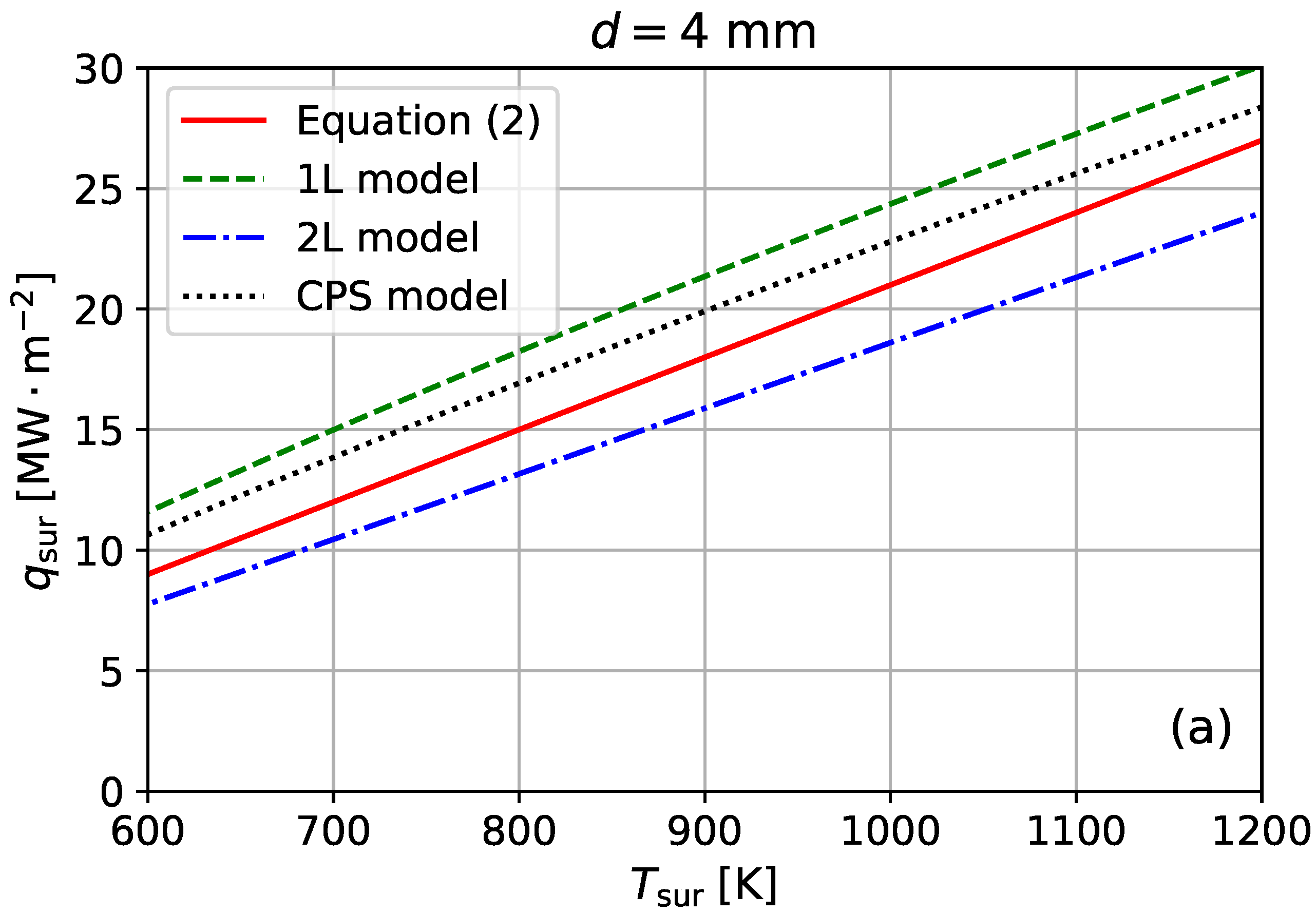
Figure 2 shows the heat flux
dependence on the surface temperature
within the framework of the three considered substrate models and the simplified Equation (2). The calculations were carried out for the reverse side target temperature
K and different substrate thicknesses. It is assumed that the values of
d,
,
,
are the same. Specifically for Equation (2) and 1 L model
4, 7, 10 mm, whereas for 2 L and CPS models
3, 6, 9 mm thicknesses were chosen. At a small substrate thickness,
mm, one can clearly see the difference in the fluxes given by different models, which is related to the presence of a large temperature gradient at a small thickness
d. As the substrate thickness increases, the differences between the models decrease as well as the absolute values of
. At a substrate thickness of
mm, the values of the heat fluxes obtained with different models become close.
Several calculations with varying temperatures of the reverse side of target at fixed thicknesses were also carried out. Qualitatively, the results are similar to those obtained by varying the substrate thickness. In this case, the temperature gradient increases with decreasing and vice versa. The incorporation of an additional model describing the interaction with the coolant would make it possible to quantify this temperature more precisely.
Different models can give very different results, especially in the case of small substrate thicknesses. This must be taken into account when carrying out simulations using complex 2D numerical codes.
3. Tolerable Heat Loads Model for Liquid Lithium Target
To estimate the tolerable heat loads to the LL divertor target, the substrate models described above should be supplemented with the plasma–surface interaction model that allows linking
to the operational parameters of the divertor plasma. Heat and particle fluxes coming to the LL surface from the edge plasma result in its erosion (due to both sputtering and evaporation). In turn, eroded lithium provides additional dissipation in the edge plasma (mainly due to the enhanced radiation loss) reducing the heat flux to the LL surface. These interactions form a self-regulating system manifesting itself through the vapor shielding phenomenon in particular. In what follows we build a simple model for such a system that is based on particle and power balance equations. At its core, this model is a natural development of the analytical model proposed in [
19] that considered the power balance exclusively.
Let us consider deuterium divertor plasma with lithium impurity arising due to the target plate erosion. We now focus on the most loaded flux tube that largely controls the divertor conditions. The power flux entering the divertor volume in this flux tube
is carried to the target plates along the magnetic field lines (here and in what follows we neglect the radial transport for the sake of simplicity). Inside the divertor, both deuterium and lithium radiation losses become significant and the resulting power balance in this region can be written as follows:
here,
and
are the radiation losses associated with the deuterium and lithium line emission, respectively. In high-density divertor plasma, an “effective radiation cost” (defined as the mean radiation loss per one injected atom integrated over its lifetime in the edge plasma) of hydrogen
is fairly constant and we take it equal 16.4 eV (the number is chosen to provide “ionization cost” of exactly 30 eV when combined with the ionization potential). For lithium, however,
is a strong function of electron temperature, electron density and its lifetime in the edge plasma [
12]. Therefore, we leave
as a free parameter and vary it in subsequent parametric analysis. The deuterium flux
is defined by the recycling process. The target plate designs considered do not involve flowing lithium film that could pump deuterium; hence, we presume that in a steady state, the surface layer of the LL target is filled with deuterium and there is a detailed balance between the deuterium flux to the surface and backflow of deuterium released from the surface to the plasma. The lithium flux
, on the other hand, is governed by sputtering, evaporation, and prompt redeposition
:
We assume that evaporation
from the LL surface follows the Langmuir evaporation law [
24,
25]:
here,
is the Li atomic mass (6.94 amu) and the empiric formula for the Li vapor saturated pressure can be found in [
26]. The sputtering source
accounts for the thermal sputtering exclusively, because
, which is relevant to the LL divertor targets, dominates physical sputtering by orders of magnitude. The thermal sputtering is calculated with the adatom model [
27]:
here,
,
A, and
are fitting constants and their values are taken from [
28].
We notice that prompt redeposition usually refers to the eroded particles that are ionized so close to the target plate that they return to the surface on first Larmor; moreover, it is usually accounted for using the Fussman formula [
29] in 2D transport simulations [
18,
30] or is treated as a free parameter in simple 0D models [
19]. In the latter case,
can be interpreted as a combination of prompt redeposition of the Li neutrals ionized within the first Larmor radius of the target surface and Li neutrals coming back to the target plate due to finite Li vapor pressure that is not accounted for in the evaporation source term. In what follows, for the sake of simplicity, we leave
as a free parameter.
The power flux to the target
defined by Equation (1) can also be written as a sum of the kinetic and potential energy of ions impinging the target surface (potential energy is released during the ion recombination at the surface) yielding:
Here,
is the hydrogen ionization potential equal 13.6 eV. Since the second ionization potential of lithium is much higher than the first one and most of the lithium leaving the target plate ends up immediately ionized and returns to the target plate without experiencing further ionization we take
eV, which is the first ionization potential. Thus the contribution of lithium particles that travel further away from the target plate and end up ionized to the higher charge states is neglected. Sheath heat transmission factor
is taken to be exactly 7. Furthermore, we assume that all ions in the vicinity of the target plate are at the same temperature and this temperature equals the electron temperature. This universal divertor plasma temperature at the target plate is denoted as
.
One can notice that promptly redeposited Li particles are not accounted for in both Equations (8) and (12). It is clear that promptly redeposited Li particles should be excluded from Equation (8) since their lifetimes in the edge plasma are negligible and they never reach the divertor region where electron temperature
raises to ∼ 30 eV and Li can radiate efficiently. The exclusion of promptly redeposited Li particles from the first term on the l.h.s. of Equation (12) is less obvious. Nevertheless, it is a standard approach for the edge transport codes to remove these particles entirely as if they have never entered the plasma [
18,
30]. The reason for this is that the prompt redeposition takes place inside the magnetic pre–sheath (MPS) [
31], which is of the spatial scale of ion Larmor radius and cannot be resolved in the framework MHD or transport equations. Moreover, in the tokamak divertor the magnetic field lines are strongly inclined with respect to the target plates, therefore the potential drop is no longer limited to the electrostatic Debye sheath but expands through the whole MPS and the Bohm boundary condition is effectively applied at the entrance to this layer (i.e., the ions reach the sound speed along the magnetic field lines at the MPS interface) [
32].
Therefore, the exclusion of the promptly redeposited Li from the first term on the l.h.s. of Equation (12) implies that the power required for the ionization of promptly redeposited Li inside the MPS is supplied by the third term on the l.h.s. of the Equation (12) and results in mere redistribution of the power entering the MPS between the potential and kinetic energy of the particles traveling through the MPS towards the surface, whereas the resulting heat flux to the surface remains unaffected. This is a reasonable assumption as long as the power required for the ionization of the promptly redeposited Li remains small compared to the power entering the MPS. However, as we will see later, this assumption becomes questionable in the regimes with high lithium erosion. We discuss this matter further in
Section 4.
Using Equations (9), (11), and (12), one can obtain the following equation for
:
Introducing Equation (13) to Equation (8), we obtain the equation governing the plasma temperature in the vicinity of the target plate:
For a given
and free parameters, fixed
is simply a function of the LL surface temperature
. We notice that due to the exponential dependence of
on
, the resulting
is limited on low and high ends. It is also worth noting that
,
,
, and
that enter Equations (8), (9), (13) and (14) are normal to the target surface. The temperature
obtained at given
from Equation (14) allows calculating
,
, and
with Equations (13), (11) and (9).
In
Figure 3, the dependence of
on
obtained via Equation (14) is shown for different values of
. It is calculated assuming
K,
mm,
eV and
using the one-layer model for the target substrate. It is clear that at fixed
the surface temperature
increases with increasing
leading to higher lithium erosion from the target surface.
To find the tolerable stationary heat load limit, the model described above should be supplemented with the limiting conditions defining whether the obtained solution is compatible with the core plasma performance or not. For this purpose, we use relative lithium concentration and plasma temperature in the vicinity of divertor target plates for the following reasons.
Eroded lithium atoms do not travel far from the target plated because low ionization potential lithium ions near the surface can be dragged upstream along the field lines by thermal forces and deuterium reverse flow, and from there, lithium ions can penetrate into the core plasma region across the separatrix. Lithium accumulating in the core region has virtually no impact on the radiation losses; its contribution to the fuel dilution can prove problematic. If the separatrix averaged Li concentration
reaches 10%, this would result in approximately 30% reduction in the hydrogenic specie density in the core region. Such a reduction in fuel density leads to approximately a 50% decrease in the fusion power limiting acceptable concentration of lithium impurity at the separatrix. Although the impurity concentration in the vicinity of divertor plate does not translate directly to the separatrix concentration for the sake of simplicity, we do not introduce any
ad hoc enrichment factors and assume that keeping the Li concentration inside the divertor
below 10% is required to ensure that the core plasma pollution remains manageable. From this, we obtain the first limiting condition for our model:
Unlike a conventional solid divertor, the lithium divertor can operate under high heat loads without relying on a detached plasma regime to protect it. On the other hand, deep detachment can lead to significant core plasma confinement time degradation [
33]. Therefore, it would be preferable to limit the operational window of the lithium divertor to high recycling or partial detachment regimes. In our study, we impose this limitation by keeping the plasma temperature in the vicinity of the target plate above 5 eV. Notice that this particular number is chosen for convenience; in principle, it can be set as low ≈ 1.5 eV, afterward, the model is no longer valid due to the increasing role of neutral plasma interactions and volumetric recombination [
34].
In
Figure 4, one can see the relative lithium impurity concentration in the divertor
as a function of the plasma temperature in front of the target
for the different values of
obtained with the model described above (all other free parameters are the same as before when we obtain
, as shown in
Figure 3). The operational window of the LL divertor is determined by the conditions
and
eV (shown in dashed horizontal and vertical lines, respectively). The maximum tolerable heat load to the target
is defined by the collapse of the operational window as
increases. In this particular case,
. Using this definition of
we can now perform a parametric analysis of its dependence on different free parameters of the proposed model.
4. Parametric Analysis of the Tolerable Heat Loads to the Liquid Lithium Target
Results of parametric scans over different free parameters of the model described above are shown in
Figure 5,
Figure 6 and
Figure 7. In all cases, the temperature at the rear side of the target substrate
is set to 300 K.
We notice that the resulting values of
can be mapped to the power, coming up to the edge plasma through the separatrix,
. However, doing so requires adopting specific device parameters. In this paper, we use the EU-DEMO project [
35] as an example. The corresponding value of
can be estimated using a simple formula:
Here,
R is the tokamak major radius,
—the ratio of the poloidal magnetic field to the total one,
—a factor characterizing the distribution of heat fluxes between the outer and inner divertors (for the single-null EU-DEMO project, we take
). Quantity
characterizes the transverse scale of the heat flux footprint at the target plate and is defined as the ratio of integral heat flux to its peak value [
36].
can be conveniently approximated by the following expression [
37]:
here,
is a transverse power decay width at the outer mid-plane, whereas
S characterizes heat flux profile widening inside the divertor due to cross-field transport (in this study, we take this value to be 1.5 mm).
can be estimated using the scaling law obtained in [
36]. To mitigate the peak heat flux target plates are tilted with respect to the magnetic field lines. Equation (
16) presumes that the heat flux at the most loaded flux tube
(notice that
is orthogonal to the target plate by definition) is governed by the peak of the parallel heat flux at the entrance to the divertor and the angle between the corresponding magnetic field line and target plate
. For EU-DEMO [
35], we have
mm,
, additionally, we assume
. Defined with Equation (16), values of
corresponding to the
(that is an actual output of the described model) are given in
Figure 5,
Figure 6 and
Figure 7 via the additional Y-axis on the right side. We notice that the baseline scenario for EU-DEMO prescribes
of approximately 150 MW [
35].
In
Figure 5, one can see the dependence of
on the target substrate thickness
d. Different curves correspond to different substrate models, described in
Section 2. These calculations were conducted for
and
eV. It can be readily seen that as the target substrate grows thinner, the heat flux that it can accommodate
increases, resulting in higher maximum tolerable heat loads. The thicker the target, the less of an impact the substrate model has on the obtained values of
. However, at low
d (keep in mind that DEMO designs consider target plates as thin as ∼3–4 mm [
38]), the difference in obtained values of
for different substrate models can reach 30%, which should be taken into account for in 2D simulation models. In the case of EU-DEMO, even the most favorable values of
, obtained at the minimal values of
d, yield
only, which is way below the baseline
value of 150 MW. This implies that the lithium target alone cannot provide adequate power dissipation without excessive pollution of the core plasma and therefore additional impurity injection to the edge plasma is required to mitigate the power flux from the core.
Effective radiation loss per eroded lithium particle
is an important parameter governing the efficiency of lithium vapor shielding; however, it strongly depends on the electron temperature, electron density, and eroded lithium lifetime in the edge plasma [
12]. In
Figure 6a dependence of
on
is shown with
varied from 50 to 800 eV. Similar to
Figure 5, different curves correspond to different substrate models. All the calculations were carried out assuming
and
mm. For all substrate models considered
increases linearly with increasing
. Higher eroded lithium radiation capabilities result in higher power dissipation that can be clearly seen in
Figure 6b, where the ratios
and
characterizing contributions of deuterium and lithium radiation losses to the power balance are shown. Deuterium and lithium radiation loss contributions even out at
eV with lithium contribution prevailing at higher
. However, even at the highest
considered, the contributions of lithium radiation losses to the power balance remain modest. We notice that 800 eV is likely an overestimation as 2D simulations yield
150–200 eV [
30]. The total contribution of the radiation to the power balance
also increases with increasing
; however, it does not exceed 55%, which is way below the value desired for the DEMO of ∼90%. The equivalent
(shown on the right side of
Figure 6a) is more than two times below the project parameters, indicating that an impurity injection to the divertor region is required to provide the desired level of power mitigation. Similar results have been obtained earlier, see, for example, [
18,
30].
Virtually all of the eroded lithium returns to the target surface due to prompt redeposition and the drag force with the main plasma flow. However, unlike dragged particles, the promptly redeposited ones do not contribute to the power dissipation because of their short lifetimes in the edge plasma. Therefore, the final free parameter scan performed in this study is the
scan. As discussed above in
Section 3, the power for the ionization of the promptly redeposited Li is supplied by the power entering MPS (the third term on l.h.s. of Equation (12)). Therefore, the ratio of the power required for the ionization of the promptly redeposited Li to the power entering MPS sets up a limit to the maximum
value for the chosen limiting conditions:
If
the solution becomes unphysical since the global power balance is violated and there is not enough power in the system to sustain the ionization within the MPS. For the chosen limiting conditions of
and
eV, this corresponds to the value
; therefore, the
scan is conducted in the range of 0.9 to 0.992 (we notice that these values are in line with the results of the 2D simulations [
30]).
In this case, calculations were performed for
eV and
mm. The resulting dependence of
on
is shown in
Figure 7a. One can see that
has a strong influence on
for all the substrate models considered. Increasing
from 0.9 to 0.992 leads to a factor of 2–2.5 increase in tolerable steady state heat loads. This is due to increased equilibrium surface temperature (see
Figure 7b) that allows for a more efficient heat sink via target cooling. For
that corresponds to
K, the main erosion source is lithium sputtering. At higher
, evaporation overtakes sputtering and becomes the dominant erosion source.
We stress that while
sets a formal limit to the feasibility of the model, its applicability becomes questionable at significantly lower
. Indeed, the ionization within the MPS is sustained by the electron kinetic energy, whereas the
term accounts for the kinetic energy of both electrons and ions entering the MPS; therefore, unless the coupling between electrons and ions is very strong, the power available for the ionization will be lower than power entering MPS. Moreover, as the power sink and the ionization source within the MPS increase, they will inevitably affect the structure of the boundary layer and hence the value of
at the very least. For typical cases considered in this and other papers
[
19,
30], the solutions corresponding to
imply that
of the power entering the MPS is used to sustain the prompt redeposition. This clearly indicates that one should be careful applying a simplistic approach of neglecting the promptly redeposited Li in both particle and power balance equations to 2D transport code studies of the lithium divertor tokamak solutions. It also encourages further analysis of the self-consistent treatment of the prompt redeposition and the sheath boundary layer provided by the combination of particle-in-cell simulations of the MPS structure and Monte Carlo simulations of the eroded particle trajectories [
39].
5. Conclusions
Liquid metals are promising alternatives to conventional solid tokamak PFC materials. Their main advantages are self-healing via the surface layer replenishment and higher resistance to neutron damage, resulting in increased life cycles of such components compared to the conventional solid ones. Among the possible liquid metal solutions, liquid lithium is the most explored and established candidate. Therefore, the divertor target covered with LL is a conceivable alternative to mainstream W-monoblock divertor designs.
In this paper, we proposed a model based on a power and particle balance that is capable of estimating the maximum tolerable steady state heat loads to the LL divertor targets, accounting for the vapor shielding effect and hydrogen recycling. The model is supplied with several substrate models (one-layer, two-layers, CPS models, as well as simple analytical formulas) describing the heat transfer through the bulk of the target. It is demonstrated that the heat flux transferred through the target to the coolant varies noticeably depending on the chosen model. This variation becomes more pronounced as the target substrate grows thinner, reaching for the EU-DEMO relevant thickness of 3–4 mm. This result demonstrates that the LL target substrate model chosen would have a high impact on predictive simulations with 2D edge transport codes conducted during the divertor design stage and, therefore, should be considered carefully.
The proposed model was used to evaluate the influence of the target substrate thickness d, effective lithium radiation losses per eroded particle , and prompt redeposition on the tolerable steady state heat load limit . The latter is obtained assuming that, in a steady state, lithium concentration in the divertor plasma should not exceed 10% to avoid excessive core plasma contamination and the plasma temperature at the footprint of the most loaded magnetic flux tube should remain above 5 eV to ensure that the divertor is partially detached in order to avoid the core plasma confinement degradation.
It is demonstrated that for all substrate models considered,
increases linearly with
as the dissipation inside the divertor volume increases with increasing lithium radiation capabilities. Lithium radiation dominates hydrogen one at
eV, which is only a factor of 1.5 higher compared to the mean
values obtained in the T-15MD simulations [
30] and, hence, can be considered a realistic value from our perspective. However, even if
is 3–4 times higher than the values obtained in the 2D edge simulations, the radiation losses inside the divertor do not exceed 55% of the power flux entering the divertor region. This value is far too low for efficient power mitigation in the DEMO where > 90% of the power flux entering the divertor region has to be radiated. Therefore, it is evident that the LL divertor alone cannot provide the desired level of power mitigation without a negative impact on the core plasma and an additional impurity injection to the divertor region is required. This result is not novel, and it was already shown in [
18,
30]. Here, we once again want to emphasize the importance of additional research in this direction.
It is shown that lowering the target substrate thickness and increasing prompt redeposition are favorable for increasing . In particular, increasing from 0.9 to 0.992 is 2–2.5 times higher . At high , the LL target can work in an evaporation-dominated regime without the threat of excessive core plasma contamination. Moreover, is not directly influenced by the target design; nevertheless, it indicates that keeping plasma temperature in the vicinity of the target plates high enough to provide fast lithium neutral ionization is beneficial for the operational window of the tokamak, further supporting the initial assumption that the LL divertor should be kept away from the deep detachment.
The power for the ionization of the promptly redeposited Li is supplied by the power entering MPS. The ratio of the power required for the ionization of the promptly redeposited Li to the power entering MPS sets up a limit to maximum : . If the solution becomes unphysical since the global power balance is violated and there is not enough power in the system to sustain the ionization within the MPS. It is shown that the limiting conditions chosen in this paper correspond to the value . For typical cases considered here, the solutions corresponding to imply that of the power entering the MPS is used to sustain the prompt redeposition. This clearly indicates that one should be careful when applying the simplistic approach of neglecting the promptly redeposited Li in 2D numerical studies of the LL tokamak divertor.
Thinner target designs are also naturally more favorable for both LL and solid targets as those allow for more efficient cooling. However, for solid PFC components, thin designs also pose a higher threat due to erosion and cracking, whereas self-healing LL surfaces mitigate these downsides.
We conclude that the proposed model can be used for the parametric analysis of the LL divertor’s operational limits. It can be further improved by adding the models for and , which would decrease the number of free parameters and can be supplied with more sophisticated limiting conditions if necessary. Such a fast and versatile tool could work well in conjunction with demanding 2D edge transport simulations.


