Article

Effect of Ferrule Design on Stress Distribution of Maxillary Incisor Rehabilitated with Ceramic Crown and PEEK Post–Core Material: A 3D Finite Element Analysis

Department of Biomedical Materials Science, University of Mississippi Medical Center, Jackson, MS 39216, USA
*
Author to whom correspondence should be addressed.
Ceramics 2023, 6(4), 2256-2268; https://doi.org/10.3390/ceramics6040137
Submission received: 15 September 2023 / Revised: 23 October 2023 / Accepted: 9 November 2023 / Published: 20 November 2023
(This article belongs to the Special Issue Ceramic Materials in Oral Applications)

Abstract

:
Endodontic-treated teeth with massive degrees of coronal tissue loss usually require rehabilitation with post-retained unitary crowns. This study aimed to evaluate the effect of ferrule design on the stress distribution of maxillary incisors rehabilitated with zirconia crowns using finite element analysis. Six three-dimensional models were generated according to the presence and location of ferrule (No Ferrule, Buccal Ferrule, Lingual Ferrule, Buccolingual Ferrule, and Full Ferrule). The post–core materials tested were Nickel–chromium (NiCr) and Polyetheretherketone (PEEK). A static load of 100 N at a 45-degree angle on the Lingual surface, in a region 2 mm below the incisive ridge, was applied. Von Mises stresses and contour plots of all of the models were collected and analyzed. A lower and more uniform stress distribution was observed in the Full Ferrule model compared with the remaining models. A reduction of 72% in the von Mises peak stresses was observed in the root when comparing the Full Ferrule and No Ferrule models, both with PEEK post–core material. In conclusion, the presence of an incomplete ferrule is beneficial to the stress distribution in restored post-retained crowns. The use of PEEK for post–core structures reduces the stress concentration on the posts, reducing the predisposition to irreparable root fracture.

Graphical Abstract

1. Introduction

Teeth with extensive coronal tissue loss usually require root canal treatment (RTC) followed by restoration with post-retained crowns to recover their function [1]. According to the American Association of Endodontists (AAE), more than 15 million root canals are performed each year in the United States [2]. Traditionally, metallic cast posts were used to retain or substitute (as a one-piece post–core component) the tooth abutment. The disadvantages of using metal for this purpose are corrosion, compromised aesthetics due to the metal shadow under all-ceramic crowns, and debonding surfaces between the prefabricated posts and core as well as between the post and dentin [3]. Another point to be highlighted is the elevated Young modulus found in frequently employed alloys like Nickel–chromium (NiCr) (203.60 GPa), in contrast to dentin within the root (18.60 GPa). This difference in elastic modulus tends to generate a stress concentration that increases the predisposition to root fracture. Due to all these conditions, numerous alternative materials like fiber-reinforced composites (fiberglass), titanium, and ceramics have been used as the post material in an attempt to prevent complications. While all of the aforementioned materials exhibit an elastic modulus lower than NiCr alloys (53.8, 120, and 200 GPa, respectively), they still possess an elastic modulus that is significantly higher than human dentin [1,4].
Based on this, materials with a similar or lower elastic modulus than dentin, like Polyetheretherketone (PEEK), have been suggested to produce prefabricated posts. PEEK is a semicrystalline thermoplastic polymer, with good mechanical and chemical properties, even at high temperatures [5,6]. The elastic modulus of pure PEEK is 3–4 GPa, accompanied by a tensile strength of 80 MPa. These values are lower when compared with the mechanical properties of human dentin (elastic modulus of 18.6 GPa and tensile strength of 104 MPa). In post-retained restored teeth, such differences tend to lead to reparable fractures, located in the post instead of the dental root [1,7,8]. Furthermore, the use of CAD/CAM milling, injection molding, and three-dimensional (3D) printing methodology technologies enabled PEEK, as a biomaterial, to migrate from the orthopedic to the dentistry field, initially being a promising material in the implantology and prosthodontic areas [6], and now also being investigated for customized endodontic posts [1]. For all of these reasons, pure PEEK was the material selected to be investigated in the current study for the core–post components.
Another factor that influences the success of endodontic-treated teeth restored with post-retained crowns is the presence of ferrule. Ideally, ferrule is a sound tooth structure above the crown margin with a minimum height of 1.5 mm to 2 mm, present in the whole circumference of the tooth [8,9,10]. The function of this dentin collar is to provide better stress distribution, creating a protective ferrule effect. This effect is especially important in maxillary anterior teeth, which are frequently exposed to non-axial loads, even in the normal occlusion, supporting high flexural stresses [8]. However, it is not always feasible to replicate the ideal guidelines in clinical settings. The ferrule design can be affected by the amount of destruction experienced by each tooth, commonly caused by cavities and caries excavation on the proximal sides [11]. Although studies have concluded that the design of the ferrule does not exert an influence on the biomechanical performance of endodontic-treated incisor teeth [10,12], there is consensus that the presence of an incomplete ferrule is considered a better option than the complete lack of it [9,13,14]. Many studies have assessed the impact of different ferrule heights [14,15,16] and the influence of the post material [1,17,18] in the development of non-reparable (below the cement–enamel junction—CEJ—leading to tooth extraction) or reparable (above CEJ) tooth fractures [8,19]. However, there are a lack of studies testing incomplete ferrule designs and their interaction with one-piece post–core made of PEEK related to the stress distribution of human maxillary incisors rehabilitated with monolithic zirconia crowns; thus, these are the parameters tested in this study.
Different in vitro and in silico methodologies, such as mechanical testing with physical specimens and finite element analysis (FEA) of 3D models, respectively, have been used for risk assessment for failure based on the interactions of the components of a clinical setup under load. Through computational calculations, FEA provides the estimation of the stress distribution within the various components of a complex structure, such as teeth restored with post-retained crowns. Another advantage of FEA over the tests that evaluate and collect data from physical specimens is that FEA has a non-destructive nature, which reduces testing costs and provides fast results, with the flexibility to evaluate several material and load conditions [20,21,22]. Therefore, FEA was the test selected to evaluate the stress distribution in the 3D models of the current study. The primary objective of this study was to assess the impact of the PEEK post–core material and different ferrule designs in terms of the stress distribution of a maxillary incisor based on von Mises stress, employing three-dimensional (3D) finite element analysis (FEA). The formulated hypothesis was that the presence of ferrule has a higher impact on the stress distribution throughout the components of the models when using pure PEEK as the post–core material.

2. Materials and Methods

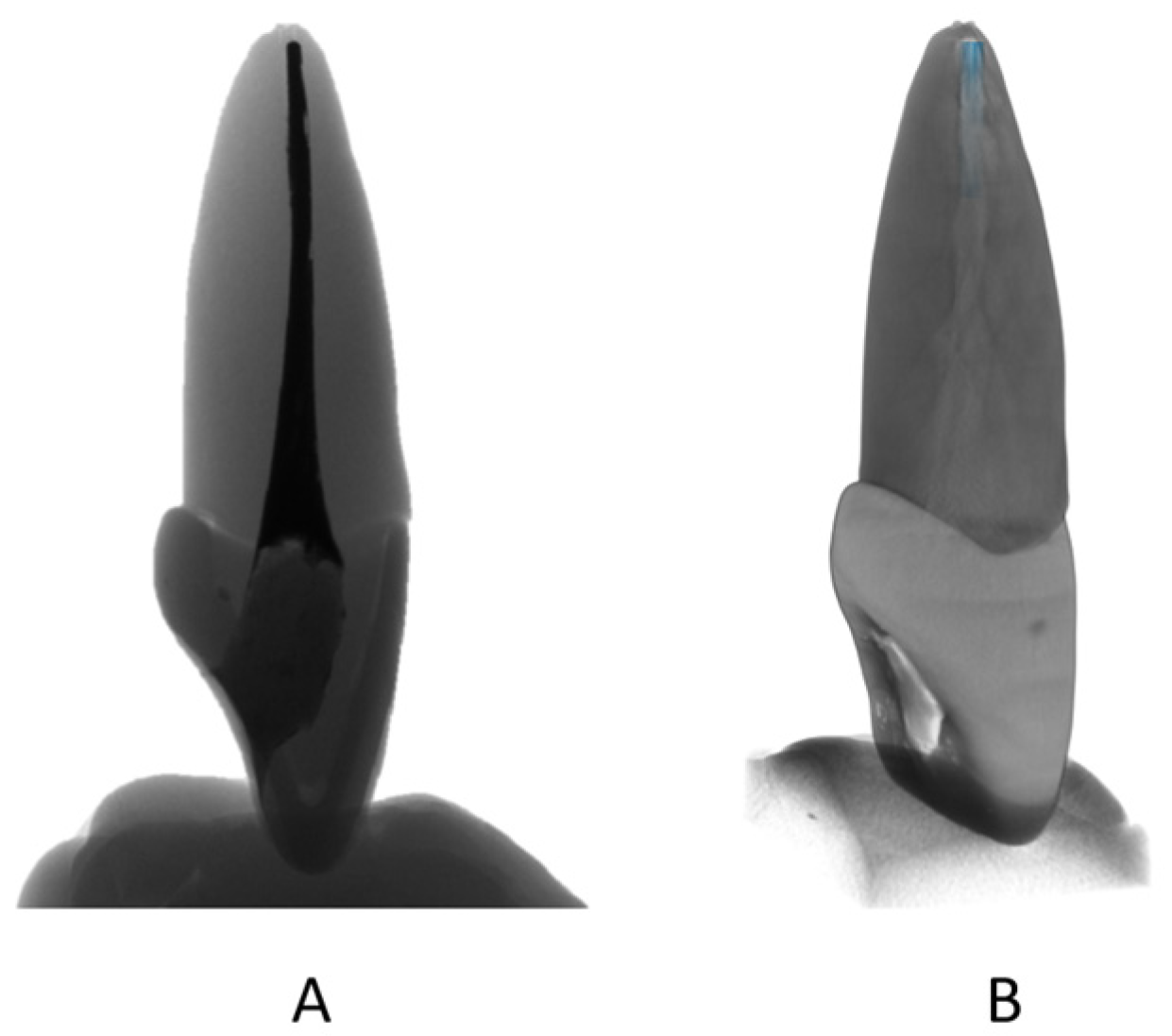
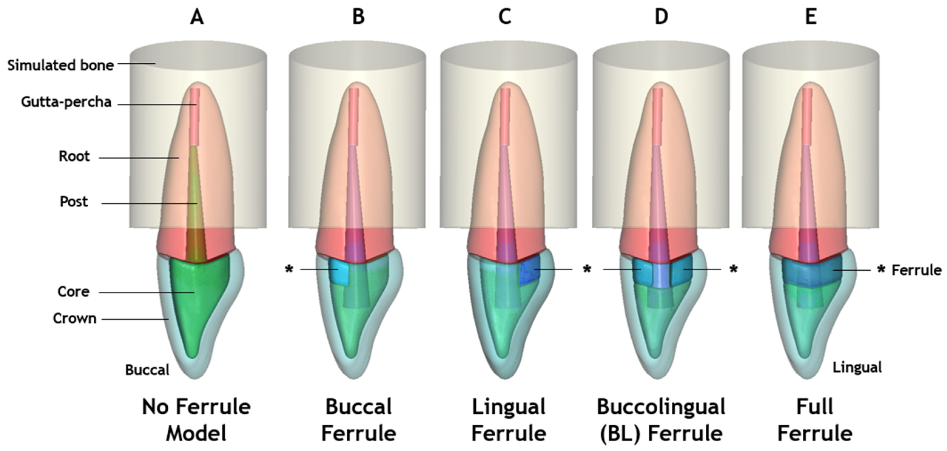
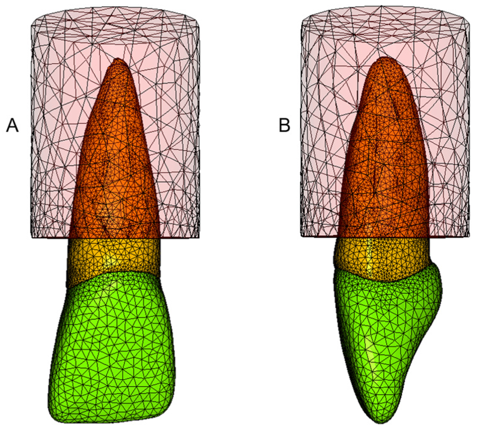
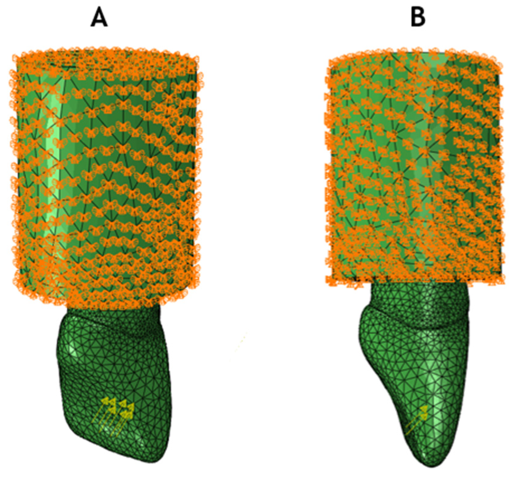
2.1. Three-Dimensional Models

A standard right central maxillary incisor for root canal treatment training (Real-T Endo AE401-8 Acadental, Lenexa, KS, USA) was scanned using micro-CT (Skyscan1172, Micro Photonics Inc., Aartselaar, Belgium). A pixel size of 34.40 μm and an operating voltage of 70 kV were used in the process. The resulting sliced images were exported and reconstructed using NRecon software (Version 1.7.4.2, Bruker; Aartselaar, Belgium). The transverse sections of the tomographic images were exported as bitmap files to interactive medical image-processing software (Synopsys Simpleware ScanIP, version T-2022.03; Mountain View, CA, USA) (Figure 1), to be processed and modified into various 3D models (Figure 2). Grayscale values were used to differentiate structures, such as dentin, and filling material. Boolean operations, 3D editing, Recursive Gaussian filter, and Create object tools were used to generate individual masks of the crown, core, ferrules, post, filling material, and simulated bone.
To create a model for all-ceramic restoration, standard tooth preparation was used. The model presented the following features: a shoulder crown/margin design ranging from 1 to 1.2 mm, a 90-degree cavosurface angle, an incisal crown thickness of 1.6 mm, and a 6-degree core inclination [23,24]. The post was designed with a conical shape, with a 14 mm length and 0.7 mm and 2.5 mm diameters in the apical and occlusal portions, respectively. Post and core were incorporated to simulate a one-piece post–core component. In the root canal treatment, 4 mm of filling material was left in the apical third. The simulated bone was placed 3 mm below the cementoenamel junction (CEJ), representing the worst-case scenario, with reduced bone support, mimicking periodontal disease. Ferrules with 2 mm height and different designs were produced. A total of 6 models were created based on their ferrule presence and location (No Ferrule model, Buccal Ferrule model, Lingual Ferrule model, Buccolingual (BL) Ferrule model, and Full Ferrule model), represented in Figure 2. Model A simulates a tooth with an absence of ferrule and model B simulates a tooth with a 2 mm ferrule only in the Buccal region, while model C presents a 2 mm ferrule exclusively in the Lingual region. Model C simulates 2 mm ferrules in both the Buccal and Lingual regions, but these are discontinued in the mesial and distal sites. Model E was built with a continuous circumferential 2 mm ferrule in the cervical tooth region.
To generate the meshing, the Simpleware module +FE Free was chosen. Tetrahedral meshes are commonly used in complex geometries like dental structures and prostheses due to being able to approximate the surface contour [25]. Therefore, higher-order tetrahedron elements with 10 nodes (C3D10), known as quadratic elements, were selected to accomplish the meshing process in the models of the present study, as exemplified in Figure 3.

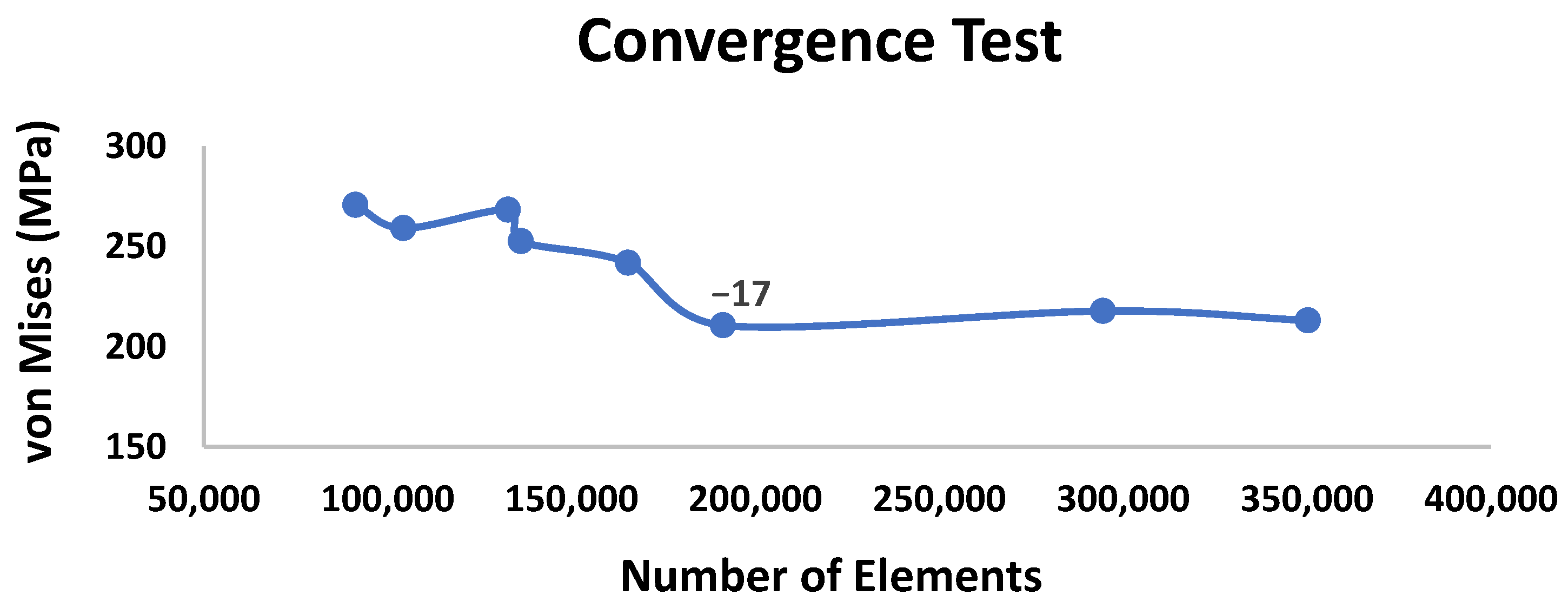
2.2. Finite Element Analysis
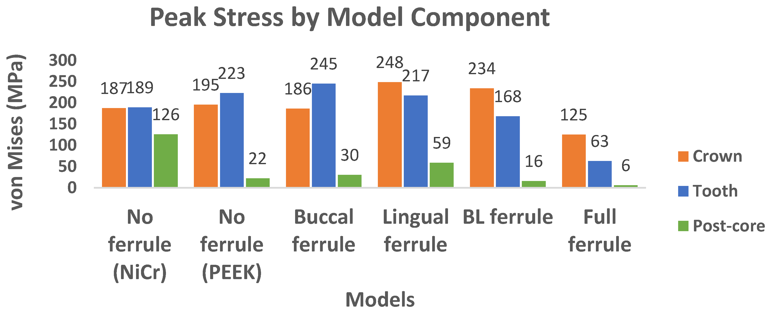
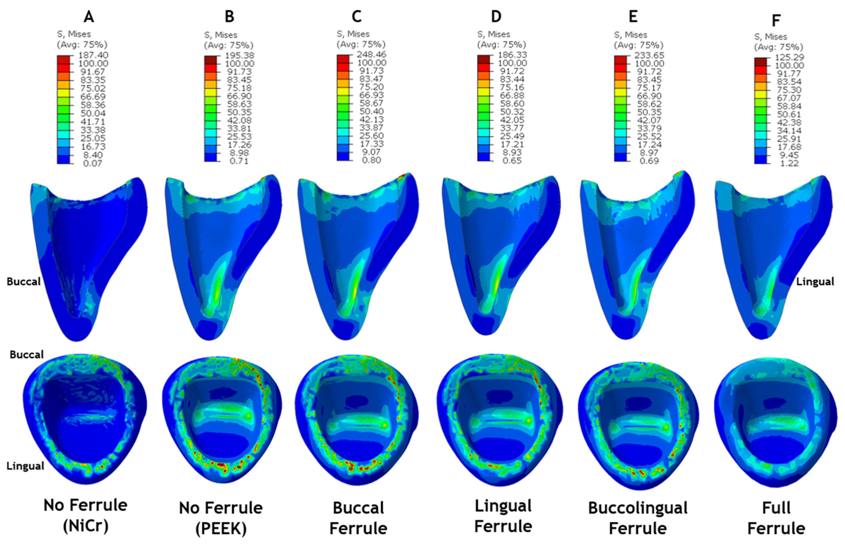
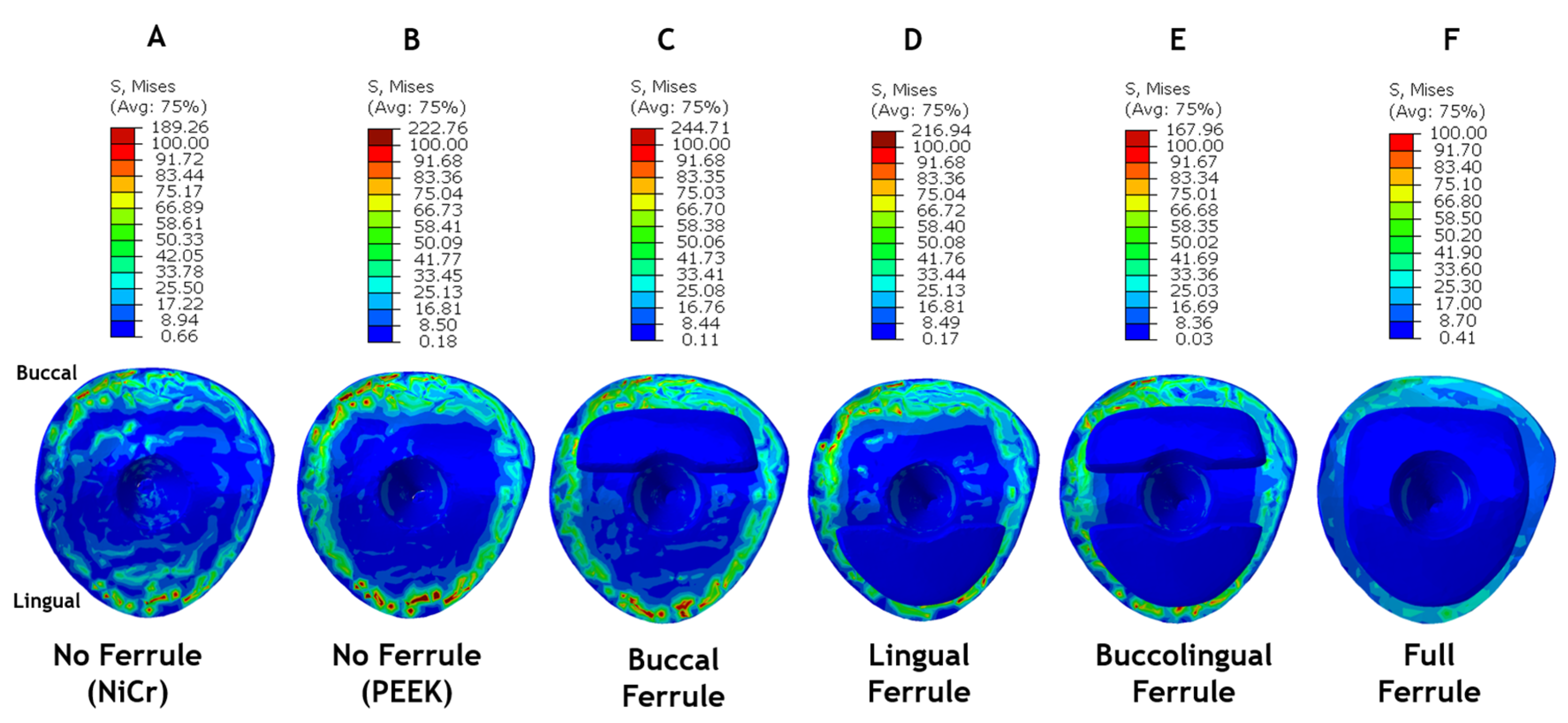
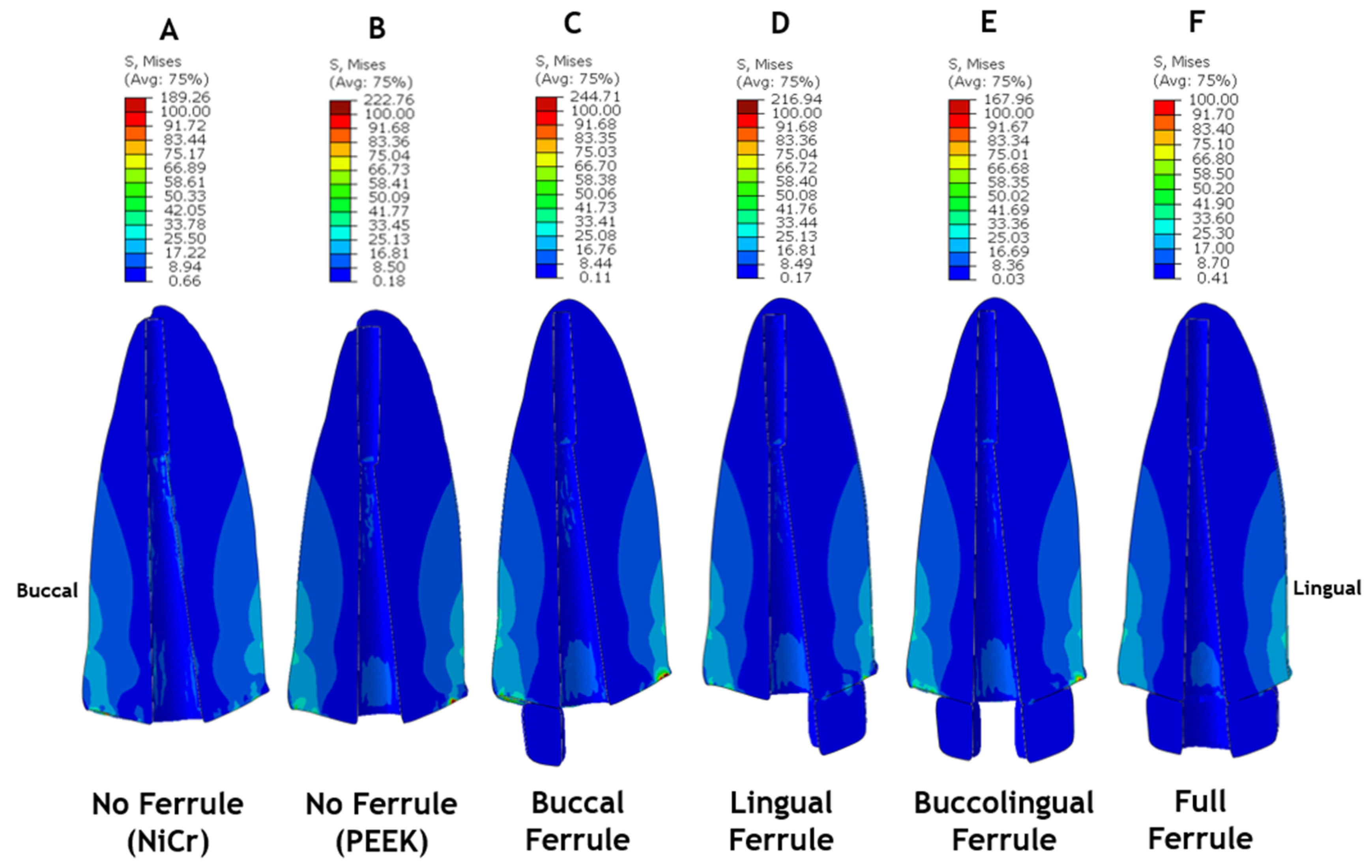
In this study, all of the materials were considered to be isotropic and homogeneous, and have linearly elastic mechanical properties. Although materials such as gutta-percha and cancellous bone present nonlinear viscoelastic behavior in clinical scenarios, which is a time-dependent viscoplastic phenomenon, simplification in material properties and also in the morphology of the components of the models is common in FEA. In static loading simulations, as in the current study, homogeneous isotropic material properties can provide acceptable results [26]. Two materials were selected for the customized post–core structure. Nickel–chromium (NiCr) was chosen as a control due to its traditional use as a one-piece post–core in endodontic practice. Pure PEEK was chosen for showing beneficial mechanical behavior, decreasing the stress concentration in all of the components of the models in previous FEA studies [1] when compared with traditional materials. The Young modulus and Poisson ratio of the materials assigned to the respective components of the mesh volumes can be seen in Table 1 [1,15,27,28,29,30,31,32].
The boundary conditions were applied to constrain the nodes on the bottom and external lateral surfaces of the supporting bone for displacement and rotation, resulting in 0 degrees of freedom in all directions. To simulate a normal occlusion, a static load of 100 N was applied at a 45-degree angle to the long axis of the tooth on the Lingual side of the clinic crown [27,33], 2 mm from the incisal edge, as depicted in Figure 4. For each experimental clinical scenario, von Mises stress data were collected [18]. The peak stress values and locations, as well as the plot contour for stress distribution behavior for the ceramic crown, root–ferrule, and post–core layers, were recorded and further analyzed.

3. Results

A total of eight mesh densities were utilized to perform the convergence test. The INP files were then exported to finite element analysis software (ABAQUS; Dassault Systèmes in Johnston, RI, USA). The number of elements and the peak stress expressed in terms of von Mises (MPa) stress for each mesh density were recorded and plotted, as seen in Figure 5. A mesh density of −17 was selected as the most adequate to be used in all the further finite element analyses since it provided a consistent result independent of the mesh refinement and a reduced computing analysis time. The number of elements for each model was 191,192 for the No Ferrule model; 338,837 for the Buccal Ferrule model; 462,879 for the Lingual Ferrule model; 330,866 for the Buccolingual model; and 324,647 for the Full Ferrule model.
The peak stress values and locations for each model were recorded using von Mises stress as the failure mode, and these can be found in Table 2. Regarding the location, the buccal side of the crown and root had most of the peak stress in the models concentrated in them, except for the Buccolingual Ferrule model. The presence of ferrule shifted the location of stresses from the root to the monolithic zirconia crown (except in the Lingual Ferrule model). Regarding the peak stress values, the Full Ferrule model demonstrated the lowest peak stress compared with the other models and exhibited a significant reduction of 44% in peak stress when compared to the No Ferrule model with pure PEEK.
The peak stress values in the monolithic zirconia crown, as well as in the root–ferrule and post–core layers, are expressed in Figure 6. Similar range values were observed in the crown component for the No Ferrule (PEEK), Buccal Ferrule, and Lingual Ferrule models. The models containing Lingual Ferrule (Lingual Ferrule and BL Ferrule models) presented the highest stresses in the crown (248 and 234 MPa, respectively) compared with the other models, while the Full Ferrule model demonstrated the lowest peak stress for this layer (125 MPa). The stress distribution in the crown for all of the models is depicted in Figure 7. It is noticeable that all of the models present a high stress concentration at the surface in contact with the tooth margin, represented by the red areas.
The contour plots for stress distribution on the transverse plane view of the ferrule and root are depicted in Figure 8, while the buccolingual cross-section views of the same components are depicted in Figure 9. The Buccal Ferrule model demonstrated the highest von Mises stress in these layers with a peak stress of 245 MPa, followed by the No Ferrule (PEEK) model with 223 MPa. The lowest von Mises stresses for root–ferrule layers were found in the Full Ferrule model (63 MPa), followed by the Buccolingual Ferrule model, with 168 MPa, and the Lingual Ferrule model (217 MPa). These results demonstrate that the presence of Lingual Ferrule can reduce the stress concentration in the root–ferrule layers (Figure 8D–F). For all of the models, peak stresses are located at the root shoulder. Figure 8F and Figure 9F demonstrate that the model with Full Ferrule and PEEK post–core material presents a more homogeneous and beneficial stress distribution.
The post–core components of the models showed peak stresses located in the core region, in contact with the tooth structures. The No Ferrule (PEEK) model showed a significant 82 percent reduction in von Mises peak stresses when compared with the No Ferrule (NiCr) model, with values of 22 MPa and 126 MPa, respectively (Figure 6). The cited contour plots of the models are depicted in Figure 10. The stress distribution in the PEEK post–core component (Figure 10A,B) was more uniform, homogeneous, and concentrated in the cervical part of the post–core structure, while in the post–core made of NiCr (Figure 10C,D), it demonstrated high stress concentration along the middle third of the post and under the applied load region. The PEEK post–core components in all of the tested models had values under 60 MPa: the Full Ferrule model had the lowest value (6 MPa), followed by the BL ferrule with 16 MPa and No Ferrule (PEEK) with 22 MPa, and then the Buccal (30 MPa) and Lingual (59 MPa) Ferrule models.

4. Discussion

It was proved that the predictions from finite element analysis (FEA) closely matched the results of strength tests when simulating endodontic-treated teeth restored with post–core systems [29]. This alignment between experimental and FEA estimations has established FEA as a reliable method for assessing stresses in post–core restored teeth. As a result, several studies [15,16,18,29,31,34,35,36,37,38], including the present one, have utilized FEA to evaluate post–core systems. A large variety of materials have been evaluated to produce prefabricated posts and post–core structures [34]. According to the literature, materials with dentin-like biomechanical properties can reduce the risk of tooth fracture and debonding [17,37].
In the present study, pure PEEK was the material selected to be investigated using in silico methodology. Few recent studies have used similar post and core materials and an FEA approach on maxillary incisors [36,37]. Tekin et al. [37] compared two different post materials (glass fiber and PEEK post) supporting metaloceramic and PEEK crowns, under similar loads and directions. The authors, in agreement with the current study, also concluded that posts made of PEEK reduce the stress in the structures of endodontic restored teeth when compared with other materials, consequently reducing the risk of irreversible tooth fracture. Nahar and collaborators [36] analyzed fiber-reinforced composite (FRC), carbon fiber-reinforced Polyetheretherketone (CFR-PEEK), glass fiber-reinforced Polyetheretherketone (GFR-PEEK), and polyetherketoneketone (PEKK) post materials with a composite resin core. The results pointed out that lower von Mises stresses were observed in dentin when using a CFR-PEEK post rather than the remaining tested materials. They also mentioned that stress parameters were consistently observed to remain below the critical failure limits for dentin, both in terms of tensile (135 MPa) and compressive (297 MPa) thresholds, across all variations of posts employed. In the present study, von Mises stress was utilized as the failure mode, which demonstrated the resultant vector of all forces combined; however, all of the models were below the dentin threshold for compressive stresses, while only the Full Ferrule model was under the tensile limit.
Core–posts made of PEEK were also tested in vitro in recent studies [39,40]. Sugano et al. [40] prepared experimental specimens using extracted bovine mandibular incisors without ferrule. PEEK was present in two groups: PEEK post and PEEK post in glass fiber sleeve. The one-piece core–post specimens were submitted to a 45° compressive load with the long axis at a speed of 1.0 mm/min until fracture. Based on the maximum load to fracture, the researchers concluded that glass fiber post, glass fiber post in glass fiber sleeve, and PEEK post in glass fiber sleeve showed a higher fracture load when compared with other groups and therefore were recommended in cases with flared root canals. Ahmad et al. [39] carried out similar tests using 58 human permanent maxillary central incisors divided into two groups: prefabricated PEEK post plus composite core and PEEK custom-made post–core. The specimens were submitted to a pullout resistance test or fracture strength test after restoration with IPS e-max CAD crown. They concluded that both groups presented similar pullout resistance but the prefabricated posts were more resistant to fracture. The prevalent mode of failure for prefabricated posts was core displacement or fracture, while in the PEEK post–core single-units, the failure occurred in either the crown or the post. Such findings corroborate the stress distribution found in the current study. The models with Lingual Ferrule (Lingual Ferrule and BL Ferrule models) presented the highest stresses in the crown (248 and 234 MPa, respectively) but lower stresses in the root–ferrule layers (217 MPa for the Lingual Ferrule model and 168 MPa for the BL Ferrule model), compared with the other models with incomplete ferrule designs using PEEK. Although the ceramic crowns were subjected to high stresses, they presented a higher Young modulus than the dentin in the root (Table 1) and therefore were able to withstand higher stresses. In addition, if the load applied exceeded the crown material resistance, the fracture would have a reparable nature, via crown replacement.
A couple of clinical cases [41,42] restoring maxillary incisors with custom-made PEEK post–core supporting single-unit lithium disilicate ceramic crowns, are present in the literature. In both of them, a ferrule of at least 2 mm was present. In the 5-year follow-up report [41], debonding was not observed and PEEK was considered to be an appropriate material to successfully restore central incisors. Another report, with a 3-year follow-up, concluded that PEEK can be a viable alternative for post materials. The authors also highlighted the fact that this material has a lower cost compared with gold and zirconia cast posts but can be more time-consuming and expensive to use when compared with prefabricated fiber posts because of the indirect laboratory technique. In both cases, the restorative components did not present failure, which is what led the authors to conclude that more clinical studies and long-term follow-ups are necessary to evaluate the longevity of customized PEEK posts in clinical scenarios.
A few studies [10,12,43,44,45,46] have tested the influence of incomplete ferrule designs on fracture resistance and failure modes of endodontically treated maxillary incisors restored with a unitary crown, with contradictory conclusions. Dikbas et al. [12] and Figueiredo et al. [10] tested the same ferrule designs as the current study with in vitro compressive and cyclic load modes, respectively. Both studies used fiberglass posts and concluded that there was no influence of the ferrule design on the fracture resistance and failure mode, which goes against the conclusion of the present study, for posts made of PEEK. Nonetheless, there is a greater number of in vitro studies that have indicated a positive correlation between ferrule design and fracture resistance. Two in vitro studies [44,46] submitted their physical specimens, with post material other than PEEK, to compressive load until failure. The remaining parameters utilized were the same as those in the current study. The authors concluded that the presence of incomplete ferrules influenced fracture resistance and the failure modes. Also, the authors observed that the location of the remaining sound tooth structure matters, with the Lingual being the most beneficial when Full Ferrule is impossible to achieve. These findings agree with the stress distribution in the models with incomplete ferrule, shown in the present study, where the presence of Lingual Ferrule decreased the peak stress in the root–ferrule layers. Another study [45] analyzed sixty maxillary anterior teeth during a chewing simulation test and reached the same conclusion about the importance of Lingual Ferrule in incomplete ferrule designs for teeth restored using quartz fiber posts. While numerous in vitro studies have assessed the influence of both complete and incomplete ferrules on the fracture resistance of anterior maxillary teeth, none of these studies selected PEEK as the material of choice.
A recent meta-analysis [43] and systematic review [9] that encompassed incomplete ferrule designs in maxillary and mandibular teeth, with a variety of ferrule heights and post materials, concluded that the complete circumferential design is the most beneficial to improve fracture resistance. In the absence of this option, incomplete ferrules, especially on the palatal/lingual side, would be preferential. Such conclusions are in accordance with the stress distribution and peak stresses in the root layers of the models containing Lingual Ferrule.
As is the case in most of the studies, limitations in the methodology are present in the current study. In clinical scenarios, the availability or design of the ferrule structure cannot be controlled; instead, it is determined by the tooth’s history, caries removal, and the conditions following endodontic treatment. Also, the cyclic load is the prevalent but not the exclusive load mode type for maxillary incisors. Axial and lateral loads are also present due to the anterior guide and parafunctional habits, respectively, and influence the stress distribution throughout the components of the rehabilitated tooth. In addition, temperature and humidity similar to the oral environment could not be reproduced in the present study. Even considering such constraints, the results of the experiments obtained in this study could confirm the initial hypothesis suggested and demonstrate that the presence and location of ferrule have a higher impact on the stress distribution throughout the models’ components rehabilitated with pure PEEK as the post–core material.

5. Conclusions

Finite element analysis of 3D models generated using a micro-CT scan of a right central incisor demonstrated that lower and more uniform stress distributions were observed in the models with 2 mm Full Ferrule. The advantage of Full Ferrule was proven by the reduction of 72% in the von Mises peak stresses in the tooth root when comparing the models Full Ferrule and No Ferrule (PEEK). Also, the presence of Buccal Ferrules shifted the von Mises peak stresses from the tooth root to the crown, demonstrating the relevance of this ferrule location when an ideal Full Ferrule cannot be obtained. The influence of the PEEK material was more pronounced in the stress distribution of the post–core layers of the model, demonstrating a reduction of 82% in the peak von Mises stresses when compared with the post–cores made of NiCr in models with no ferrule. Such a reduction can be attributed to the lower elastic modulus of pure PEEK when compared with the mechanical properties of human dentin. Overall, all findings collectively demonstrate the excellence of PEEK as a material of choice, and the importance of the 2mm full circumferential ferrule for better stress distribution in all the components of the post-retained restored teeth. When incomplete ferrule design was the only option, the presence of the sound tooth in the Lingual region proved to be beneficial.

Author Contributions

Conceptualization, L.H.J.A. and Y.D.; clinical relevance data acquisition, L.H.J.A. and Z.Z.; methodology, L.H.J.A.; validation, Y.D.; formal analysis, L.H.J.A. and Z.Z.; investigation, L.H.J.A. and Z.Z.; resources, Y.D.; writing—original draft preparation, L.H.J.A.; writing—review and editing, Y.D., L.H.J.A. and Z.Z.; visualization, L.H.J.A.; supervision, Y.D.; project administration, Y.D.; funding acquisition, Y.D. All authors have read and agreed to the published version of the manuscript.

Funding

This research was performed during the UPSTART program at the University of Mississippi Medical Center and did not receive any specific grant from funding agencies in the public, commercial, or not-for-profit sectors.

Institutional Review Board Statement

Not applicable.

Informed Consent Statement

Not applicable.

Data Availability Statement

Data are available from the corresponding author upon reasonable request.

Conflicts of Interest

The authors declare no conflict of interest.

References

  1. Yu, H.; Feng, Z.; Wang, L.; Mihcin, S.; Kang, J.; Bai, S.; Zhao, Y. Finite Element Study of PEEK Materials Applied in Post-Retained Restorations. Polymers 2022, 14, 3422. [Google Scholar] [CrossRef] [PubMed]
  2. American Association of Endodontists (AAE). Available online: https://newsroom.aae.org/press-kit/ (accessed on 15 August 2023).
  3. Hedlund, S.O.; Johansson, N.G.; Sjögren, G. Retention of prefabricated and individually cast root canal posts in vitro. Br. Dent. J. 2003, 195, 155–158. [Google Scholar] [CrossRef] [PubMed]
  4. Özkurt, Z.; Iseri, U.; Kazazoglu, E. Zirconia ceramic post systems: A literature review and a case report. Dent. Mater. J. 2010, 29, 233–245. [Google Scholar] [CrossRef] [PubMed]
  5. Callister, W.D.; Rethwisch, D.G. Materials Science and Engineering: An Introduction; John Wiley & Sons: Hoboken, NJ, USA, 2010. [Google Scholar]
  6. Najeeb, S.; Zafar, M.S.; Khurshid, Z.; Siddiqui, F. Applications of polyetheretherketone (PEEK) in oral implantology and prosthodontics. J. Prosthodont. Res. 2016, 60, 12–19. [Google Scholar] [CrossRef] [PubMed]
  7. De Ruiter, L.; Janssen, D.; Briscoe, A.; Verdonschot, N. The mechanical response of a polyetheretherketone femoral knee implant under a deep squatting loading condition. Proc. Inst. Mech. Eng. Part H J. Eng. Med. 2017, 231, 1204–1212. [Google Scholar] [CrossRef]
  8. Assiri, A.Y.K.; Saafi, J.; Al-Moaleem, M.M.; Mehta, V. Ferrule effect and its importance in restorative dentistry: A literature Review. J. Popul. Ther. Clin. Pharmacol. 2022, 29, e69–e82. [Google Scholar] [CrossRef]
  9. Khabadze, Z.; Mordanov, O.; Taraki, F.; Magomedov, O.; Kuznetsova, A.; Solimanov, S.; Nazhmudinov, S.; Bokova, R.; Adzhieva, A.; Bakaev, Y. Effects of the Ferrule Design on Fracture Resistance to Endodontically-Treated Teeth Restored with Fiber Posts: A Systematic Review. Open Dent. J. 2019, 13, 493–498. [Google Scholar] [CrossRef]
  10. Figueiredo, F.E.; Santos, R.C.; Silva, A.S.; Valdívia, A.D.; Oliveira-Neto, L.A.; Griza, S.; Soares, C.J.; Faria, E.S.A.L. Ferrule Design Does Not Affect the Biomechanical Behavior of Anterior Teeth Under Mechanical Fatigue: An In Vitro Evaluation. Oper. Dent. 2019, 44, 273–280. [Google Scholar] [CrossRef]
  11. Mahdavi Izadi, Z.; Jalalian, E.; Eyvaz Ziaee, A.; Zamani, L.; Javanshir, B. Evaluation of the effect of different ferrule designs on fracture resistance of maxillary incisors restored with bonded posts and cores. J. Dent. 2010, 7, 146–155. [Google Scholar]
  12. Dikbas, I.; Tanalp, J.; Ozel, E.; Koksal, T.; Ersoy, M. Evaluation of the effect of different ferrule designs on the fracture resistance of endodontically treated maxillary central incisors incorporating fiber posts, composite cores and crown restorations. J. Contemp. Dent. Pract. 2007, 8, 62–69. [Google Scholar]
  13. Hinckfuss, S.; Wilson, P.R. Effect of Core Material and Restoration Design on Strength of Endodontically Treated Bovine Teeth: A Laboratory Study. J. Prosthodont. 2008, 17, 456–461. [Google Scholar] [CrossRef] [PubMed]
  14. Al-Hazaimeh, N.; Gutteridge, D.L. An in vitro study into the effect of the ferrule preparation on the fracture resistance of crowned teeth incorporating prefabricated post and composite core restorations. Int. Endod. J. 2001, 34, 40–46. [Google Scholar] [CrossRef] [PubMed]
  15. Upadhyaya, V.; Bhargava, A.; Parkash, H.; Chittaranjan, B.; Kumar, V. A finite element study of teeth restored with post and core: Effect of design, material, and ferrule. Dent. Res. J. 2016, 13, 233. [Google Scholar] [CrossRef] [PubMed]
  16. Mosharaf, R.; Abolhasani, M.; Fathi, A.H.; Rajabi, A. The Effect of Ferrule/Crown Ratio and Post Length on the Applied Stress and Strain Distribution to the Endodontically Treated Maxillary Central Teeth: A Finite Element Analysis. Front. Dent. 2023, 20, 16. [Google Scholar] [CrossRef]
  17. Santos, A.F.; Meira, J.B.; Tanaka, C.B.; Xavier, T.A.; Ballester, R.Y.; Lima, R.G.; Pfeifer, C.S.; Versluis, A. Can fiber posts increase root stresses and reduce fracture? J. Dent. Res. 2010, 89, 587–591. [Google Scholar] [CrossRef]
  18. Tagahara, A.; Masaki, C.; Nodai, T.; Munemasa, T.; Mukaibo, T.; Kondo, Y.; Hosokawa, R. Stress Distribution in Maxillary Central Incisors without Ferrules: A Finite Element Analysis of Post and Core Systems. Open J. Stomatol. 2021, 11, 251–262. [Google Scholar] [CrossRef]
  19. Santos, T.D.S.A.; Abu Hasna, A.; Abreu, R.T.; Tribst, J.P.M.; De Andrade, G.S.; Borges, A.L.S.; Torres, C.R.G.; Carvalho, C.A.T. Fracture resistance and stress distribution of weakened teeth reinforced with a bundled glass fiber–reinforced resin post. Clin. Oral. Investig. 2022, 26, 1725–1735. [Google Scholar] [CrossRef]
  20. Alberto, L.H.J.; Kalluri, L.; Esquivel-Upshaw, J.F.; Duan, Y. Three-Dimensional Finite Element Analysis of Different Connector Designs for All-Ceramic Implant-Supported Fixed Dental Prostheses. Ceramics 2022, 5, 34–43. [Google Scholar] [CrossRef]
  21. Alberto, L.H.J.; Kalluri, L.; Esquivel-Upshaw, J.F.; Duan, Y. Finite Element Analysis of an Implant-Supported FDP with Different Connector Heights. Symmetry 2022, 14, 2334. [Google Scholar] [CrossRef]
  22. Meira, J.B.C.; Jikihara, A.N.; Capetillo, P.; Roscoe, M.G.; Cattaneo, P.M.; Ballester, R.Y. Finite Element Analysis in Dentistry. In Dental Biomaterials; World Scientific: Singapore, 2018; Volume 2, pp. 67–89. [Google Scholar]
  23. Ahmed, W.M.; Abdallah, M.-N.; McCullagh, A.P.; Wyatt, C.C.L.; Troczynski, T.; Carvalho, R.M. Marginal Discrepancies of Monolithic Zirconia Crowns: The Influence of Preparation Designs and Sintering Techniques. J. Prosthodont. 2019, 28, 288–298. [Google Scholar] [CrossRef]
  24. Bernauer, S.A.; Müller, J.; Zitzmann, N.U.; Joda, T. Influence of Preparation Design, Marginal Gingiva Location, and Tooth Morphology on the Accuracy of Digital Impressions for Full-Crown Restorations: An In Vitro Investigation. J. Clin. Med. 2020, 9, 3984. [Google Scholar] [CrossRef]
  25. Mehmert, P. Chapter Eleven—Residual stress analysis and geometrical tolerances in powder bed fusion and direct energy deposition processes. In Quality Analysis of Additively Manufactured Metals; Kadkhodapour, J., Schmauder, S., Sajadi, F., Eds.; Elsevier: Amsterdam, The Netherlands, 2023; pp. 429–486. [Google Scholar] [CrossRef]
  26. Celik, H.K.; Koc, S.; Kustarci, A.; Rennie, A.E.W. A literature review on the linear elastic material properties assigned in finite element analyses in dental research. Mater. Today Commun. 2022, 30, 103087. [Google Scholar] [CrossRef]
  27. Nokar, S.; Bahrami, M.; Mostafavi, A.S. Comparative Evaluation of the Effect of Different Post and Core Materials on Stress Distribution in Radicular Dentin by Three-Dimensional Finite Element Analysis. J. Dent. 2018, 15, 69–78. [Google Scholar]
  28. Hallak, A.G.; Caldas, R.A.; Silva, I.D.; Miranda, M.E.; Brandt, W.C.; Vitti, R.P. Stress distribution in restorations with glass fiber and polyetheretherketone intraradicular posts: An in silico analysis. Dent. Mater. J. 2022, 41, 376–381. [Google Scholar] [CrossRef] [PubMed]
  29. Lee, K.-S.; Shin, J.-H.; Kim, J.-E.; Kim, J.-H.; Lee, W.-C.; Shin, S.-W.; Lee, J.-Y. Biomechanical Evaluation of a Tooth Restored with High Performance Polymer PEKK Post-Core System: A 3D Finite Element Analysis. BioMed Res. Int. 2017, 2017, 1373127. [Google Scholar] [CrossRef]
  30. Huang, L.; Nemoto, R.; Okada, D.; Shin, C.; Saleh, O.; Oishi, Y.; Takita, M.; Nozaki, K.; Komada, W.; Miura, H. Investigation of stress distribution within an endodontically treated tooth restored with different restorations. J. Dent. Sci. 2022, 17, 1115–1124. [Google Scholar] [CrossRef]
  31. Adigüzel, Ö.; Kaya, S.; Yiğit Özer, S.; Değer, Y.; Göncü Başaran, E.; Yavuz, İ. Three-dimensional Finite Element Analysis of Endodontically Treated Tooth Restored with Carbon and Titanium Posts. Int. Dent. Res. 2011, 1, 55. [Google Scholar] [CrossRef]
  32. Alper, B.; Gultekin, P.; Yalci, S. Application of Finite Element Analysis in Implant Dentistry. In Finite Element Analysis: New Trends and Developments; InTech: Rijeka, Croatia, 2012. [Google Scholar] [CrossRef]
  33. Zhou, T.F.; Zhang, X.H.; Wang, X.Z. Three-dimensional finite element analysis of one-piece computer aided design and computer aided manufacture involved zirconia post and core. Beijing Da Xue Xue Bao Yi Xue Ban 2015, 47, 78–84. [Google Scholar]
  34. Badami, V.; Ketineni, H.; Pb, S.; Akarapu, S.; Mittapalli, S.P.; Khan, A. Comparative Evaluation of Different Post Materials on Stress Distribution in Endodontically Treated Teeth Using the Finite Element Analysis Method: A Systematic Review. Cureus 2022, 14, e29753. [Google Scholar] [CrossRef]
  35. Kharboutly, N.A.-D.; Allaf, M.; Kanout, S. Three-Dimensional Finite Element Study of Endodontically Treated Maxillary Central Incisors Restored Using Different Post and Crown Materials. Cureus 2023, 15, e33778. [Google Scholar] [CrossRef]
  36. Nahar, R.; Mishra, S.K.; Chowdhary, R. Evaluation of stress distribution in an endodontically treated tooth restored with four different post systems and two different crowns- A finite element analysis. J. Oral. Biol. Craniofacial Res. 2020, 10, 719–726. [Google Scholar] [CrossRef] [PubMed]
  37. Tekin, S.; Adiguzel, O.; Cangul, S.; Atas, O.; Erpacal, B. Evaluation of the use of PEEK material in post-core and crown restorations using finite element analysis. Am. J. Dent. 2020, 33, 251–257. [Google Scholar] [PubMed]
  38. Nakamura, T.; Ohyama, T.; Waki, T.; Kinuta, S.; Wakabayashi, K.; Mutobe, Y.; Takano, N.; Yatani, H. Stress Analysis of Endodontically Treated Anterior Teeth Restored with Different Types of Post Material. Dent. Mater. J. 2006, 25, 145–150. [Google Scholar] [CrossRef] [PubMed]
  39. Ahmad, S.M.; Dawood, S.N.; Dalloo, G.A.M.; Al-Barazanchi, T.R.H. Evaluation of mechanical properties of different polyetheretherketone endodontic post systems: An in vitro study. BMC Oral Health 2023, 23, 537. [Google Scholar] [CrossRef]
  40. Sugano, K.; Komada, W.; Okada, D.; Miura, H. Evaluation of composite resin core with prefabricated polyetheretherketone post on fracture resistance in the case of flared root canals. Dent. Mater. J. 2020, 39, 924–932. [Google Scholar] [CrossRef]
  41. Kasem, A.T.; Shams, M.; Tribst, J.P.M. The Use of Polyetheretherketone (PEEK) as an Alternative Post and Core Material: Five-Year Follow-Up Report. Dent. J. 2022, 10, 237. [Google Scholar] [CrossRef]
  42. Zoidis, P. The Use of Modified Polyetheretherketone Post and Core for an Esthetic Lithium Disilicate Anterior Ceramic Restoration: A Clinical Report. Int. J. Prosthodont. 2021, 34, 120–125. [Google Scholar] [CrossRef]
  43. Al-sanabani, F.; Al-Makramani, B.; Alaajam, W.; Al-ak’hali, M.; Alhajj, M.; Nassani, M.Z.; Assad, M.; Al-Maweri, S. Effect of partial ferrule on fracture resistance of endodontically treated teeth: A meta-analysis of in-vitro studies. J. Prosthodont. Res. 2023, 67, 348–359. [Google Scholar] [CrossRef]
  44. Muangamphan, P.; Sattapan, B.; Kukiattrakoon, B.; Thammasitboon, K. The effect of incomplete crown ferrules on fracture resistance and failure modes of endodontically treated maxillary incisors restored with quartz fiber post, composite core, and crowns. J. Conserv. Dent. 2015, 18, 187–191. [Google Scholar] [CrossRef]
  45. Naumann, M.; Preuss, A.; Rosentritt, M. Effect of incomplete crown ferrules on load capacity of endodontically treated maxillary incisors restored with fiber posts, composite build-ups, and all-ceramic crowns: An in vitro evaluation after chewing simulation. Acta Odontol. Scand. 2006, 64, 31–36. [Google Scholar] [CrossRef]
  46. Ng, C.C.; Dumbrigue, H.B.; Al-Bayat, M.I.; Griggs, J.A.; Wakefield, C.W. Influence of remaining coronal tooth structure location on the fracture resistance of restored endodontically treated anterior teeth. J. Prosthet. Dent. 2006, 95, 290–296. [Google Scholar] [CrossRef]
Figure 1. Standard right central incisor for root canal treatment training. (A) Tomographic image produced using micro-CT; (B) resultant image after importing slices to Simpleware.
Ceramics 06 00137 g001
Figure 2. Three-dimensional models generated with different ferrule designs (represented in blue colors and indicated with an asterisk). (A) No Ferrule model; (B) Buccal Ferrule model; (C) Lingual Ferrule model; (D) Buccolingual (BL) Ferrule model; and (E) Full Ferrule model.
Ceramics 06 00137 g002
Figure 3. Models meshed with tetrahedron quadratic elements. (A) Frontal view; (B) lateral view.
Ceramics 06 00137 g003
Figure 4. Boundary and load conditions. Constricted nodes are represented in orange, while the load direction and location are represented by yellow arrows. (A) Lingual view; (B) lateral view.
Ceramics 06 00137 g004
Figure 5. Convergence test data.
Ceramics 06 00137 g005
Figure 6. Peak stress values of all models’ component layers expressed in von Mises stress (MPa).
Ceramics 06 00137 g006
Figure 7. Contour plot for stress distribution on the crown. The top row represents the buccolingual cross-section view and the bottom row represents the transverse plane view. Models: (A) No Ferrule (NiCr); (B) No Ferrule (PEEK); (C) Buccal Ferrule; (D) Lingual Ferrule; (E) Buccolingual Ferrule; and (F) Full Ferrule.
Ceramics 06 00137 g007
Figure 8. Transverse plane view of stress distribution contour plots of ferrule and root model components. Models: (A) No Ferrule (NiCr); (B) No Ferrule (PEEK); (C) Buccal Ferrule; (D) Lingual Ferrule; (E) Buccolingual Ferrule; and (F) Full Ferrule.
Ceramics 06 00137 g008
Figure 9. Contour plot for stress distribution on the buccolingual cross-section of the root and ferrule. Models: (A) No Ferrule (NiCr); (B) No Ferrule (PEEK); (C) Buccal Ferrule; (D) Lingual Ferrule; (E) Buccolingual Ferrule; and (F) Full Ferrule.
Ceramics 06 00137 g009
Figure 10. Contour plot for stress distribution on the post–core layers of models without ferrule. (A) Lingual view of the No Ferrule model (PEEK); (B) Buccal view of the No Ferrule model (PEEK); (C) Lingual view of the No Ferrule model (NiCr); and (D) Buccal view of the No Ferrule model (NiCr).
Ceramics 06 00137 g010
Table 1. Material properties assigned to the components of the mesh volumes.
Model
Component
MaterialYoung’s Modulus (GPa)Poison’s RatioReferences
Bone supportCancellous bone1.370.30[1,28]
Filling materialGutta-percha0.690.45[1,31]
Root, ferruleDentin18.600.31[1,29]
Post, coreNickel–chromium (NiCr)203.600.30[15]
Pure PEEK4.100.40[1,30]
CrownZirconia200.000.33[27,32]
Table 2. Peak stress values and locations by model recorded using von Mises stress as the failure mode.
Assembly ModelPeak Stress
(von Mises—MPa)
Location
No ferrule (NiCr)189Root (buccal)
No ferrule (PEEK)223Root (buccal)
Buccal ferrule248Crown (buccal)
Lingual ferrule217Root (buccal)
Buccalingual ferrule234Crown (lingual)
Full ferrule125Crown (buccal)
Disclaimer/Publisher’s Note: The statements, opinions and data contained in all publications are solely those of the individual author(s) and contributor(s) and not of MDPI and/or the editor(s). MDPI and/or the editor(s) disclaim responsibility for any injury to people or property resulting from any ideas, methods, instructions or products referred to in the content.

