Article

Impact Characteristics and Repair Approaches of Distinct Bio-Based Matrix Composites: A Comparative Analysis

by
Bharath Ravindran
1,
Timotheos Agathocleous
2,
Beate Oswald-Tranta
2,
Ewald Fauster
1 and
Michael Feuchter
3,*
1
Processing of Composites Group, Department of Polymer Engineering, Montanuniversität Leoben, 8700 Leoben, Austria
2
Department of Product Engineering, Chair of Automation and Measurement, Montanuniversität Leoben, 8700 Leoben, Austria
3
Department of Polymer Engineering, Chair of Material Science and Testing of Polymers, Montanuniversität Leoben, 8700 Leoben, Austria
*
Author to whom correspondence should be addressed.
J. Compos. Sci. 2024, 8(4), 126; https://doi.org/10.3390/jcs8040126
Submission received: 7 March 2024 / Revised: 21 March 2024 / Accepted: 27 March 2024 / Published: 29 March 2024
(This article belongs to the Special Issue Characterization and Modelling of Composites, Volume III)

Abstract

:
Increasing global concerns regarding environmental issues have driven significant advancements in the development of bio-based fiber reinforced polymer composites. Despite extensive research on bio-composites, there remains a noticeable gap in studies specifically addressing the challenges of repairing bio-composites for circular economy adoption. Traditional repair techniques for impacted composites, such as patching or scarf methods, are not only time-consuming but also require highly skilled personnel. This paper aims to highlight cost-effective repair strategies for the restoration of damaged composites, featuring flax fiber as the primary reinforcement material and distinct matrix systems, namely bio-based epoxy and bio-based vitrimer matrix. Glass fiber was used as a secondary material to validate the bio-based vitrimer matrix. The damage caused specifically by low impact is detrimental to the structural integrity of the composites. Therefore, the impact resistance of the two composite materials is evaluated using instrumented drop tower tests at various energy levels, while thermography observations are employed to assess damage evolution. Two distinct repair approaches were studied: the resin infiltration repair method, employing bio-based epoxy, and the reconsolidation (self-healing) repair method, utilizing the bio-based vitrimer matrix. The efficiency of these repair methods was assessed through active thermography and compression after impact tests. The repair outcomes demonstrate successful restoration and the maintenance of ultimate strength at an efficiency of 90% for the re-infiltration repair method and 92% for the reconsolidation repair method.

1. Introduction

Due to growing concerns about environmental issues and sustainability, significant progress has been observed in the development of green materials, particularly through the advancement of bio-composites [1]. The scientific and industrial communities increasingly recognize the importance of eco-friendly materials, recycling, and reusing, driven by the rising demand for alternatives to nonrenewable resources. In this context, bio-composites derived from biofibers and biopolymers have gathered significant attention as they can provide necessary properties and functionalities at reasonable costs [2]. These bio-composites have become the focus of extensive research due to their specific properties, sustainable sourcing, biodegradability, low density, and cost-effectiveness [3,4]. Consequently, they are being applied as engineering materials in various fields, such as automotive, construction, packaging, and sporting goods, serving as a sustainable alternative to fiberglass composites in structural applications [5]. The mechanical behavior of bio-composites has been extensively studied [6,7,8,9,10,11] and, among various natural fibers, flax stands out as one of the most promising alternatives in terms of strength and stiffness. Flax-based composites are reported to exhibit specific strengths comparable to glass fiber-reinforced plastics [12], making flax fibers a suitable substitute for glass fibers and allowing engineers to design materials with enhanced structural integrity.
In recent years, to mitigate the adverse environmental effects of petrochemical-based polymers, the development of bio-based resins has emerged as a viable alternative. Epoxy thermosets, with their established utility across various functional and structural applications, have gathered significant attention for the creation of compatible bio-based epoxy resins [13]. However, the inherent thermosetting nature of bio-based epoxy systems presents a notable challenge, rendering them unsuitable for conventional reprocessing, repair, or recycling methods [14] commonly applied to thermoplastics. This limitation raises significant concerns regarding the prolonged efficiency of these materials and the complexities in managing their end-of-life scenarios. To meet the imperatives of green chemistry and circular economy practices, bio-based precursors have been increasingly integrated into transesterification vitrimers [15]. Consequently, increasingly advanced bio-based vitrimers have been developed. Many bio-based platforms, including lignin [16,17,18], epoxidized linseed oil [19,20,21,22,23], and epoxidized soybean oil [23,24,25,26,27], have entered the vitrimer market as alternative feedstock to create more reversible and sustainable material systems. However, the development of these bio-composites is still in its emerging stages concerning the adaptation to circular economy principles, and the literature contains fragmented data on their repair, recycling, and reprocessing.
Repair, which is integral to circular economy principles aimed at extending product lifetime, enables savings in raw materials and energy, and contributes to waste reduction. Over the past few decades, numerous studies have been developed and reported effective repair methods for restoring the mechanical properties of composite structures, such as scarf repair, patch repair, stepped lap repair, injection repair, and self-healing repair [28,29,30,31,32,33,34,35,36,37,38,39,40,41]. The results show a wide range in the repaired laminate’s strength, suggesting that specimens are restored to nearly perfect condition or better. This can be attributed to variations in materials and repair methods, which result in repair efficiencies ranging from 70% to 114%. However, bonded scarf and patch repairs are known for their high costs in terms of time, materials, equipment, and skilled labor [29,42]. In this context, the development of cost-effective repair approaches such as resin reinfiltration and self-healing materials deserves attention. These technologies offer the potential to extend the useful lifetime of materials, reducing the ecological and economic costs associated.
Thus, the current study focuses on the development of cost-effective repair strategies for restoring damaged composites, utilizing distinct bio-based matrix systems. These composites undergo low energy impact tests, as structures are often subjected to impact loads from dropped tools and unloading fixtures. Although these impacts are often barely visible, they lead to internal damage that significantly reduces the residual mechanical properties of the composites. Consequently, the impact characteristics of various bio-based matrix composites are evaluated through instrumented drop tower tests at different energy levels, with thermography observations employed to assess damage evolution. Two distinct repair approaches are then implemented: the resin infiltration repair method using bio-based epoxy and the reconsolidation (self-healing) repair method utilizing the bio-based vitrimer matrix. The efficiency of these repair methods is assessed through active thermography and compression after impact tests.

2. Materials and Specimen Manufacturing
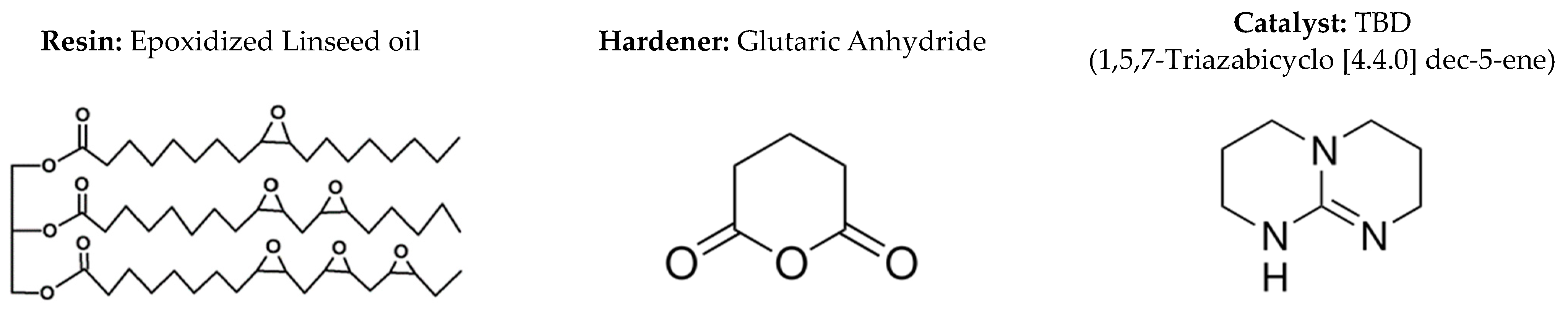
2.1. Materials

The primary reinforcement used is flax fiber, known as Amplitex 5042, supplied by Bcomp Ltd., Fribourg, Switzerland. The reinforcement is a woven fabric in a balanced 4 × 4 twill weave architecture with yarn of 500 tex having no twist and areal density of 500 g/m2 [43]. The glass fiber, Interglas FK144 supplied by Porcher Industries GmbH, Erbach, Germany, is chosen as the secondary reinforcement material. This glass fiber reinforcement is a plain weave fabric with an areal density measuring 395 g/m2.
The bio-based epoxy matrix comprises Epinal b.poxy IR78.31 (with a bio-based resin content of 37.58%) and Epinal IH77.11 amine hardener supplied by bto-epoxy GmbH (Amstetten, Austria). The resin and hardener are mixed in the ratio of 100:25 by weight. The bio-based vitrimer matrix system consists of three components: the resin (Epinal NFL 10.20-A4.00) is a commercial epoxidized linseed oil (ELSO) with an epoxy equivalent weight of 174 g/mol, the catalyst (TBD, 1,5,7-Triazabicyclo[4.4.0]dec-5-ene) with a purity >98% is supplied by bto-epoxy GmbH (Amstetten, Austria) and the hardener (Glutaric anhydride) with a purity >95% is from Sigma-Aldrich Handels GmbH (Vienna, Austria). The chemical structures of the materials are illustrated in Figure 1. The resin and curing agents are mixed at a ratio 100:34 by weight, with 10 mol% TBD (by weight) added, as this serves as an effective catalyst for transesterification reaction. Since ELSO constitutes the primary component of the resin system, it comprises approximately 70% to the bio-based content.

2.2. Preparation of Materials for Manufacturing
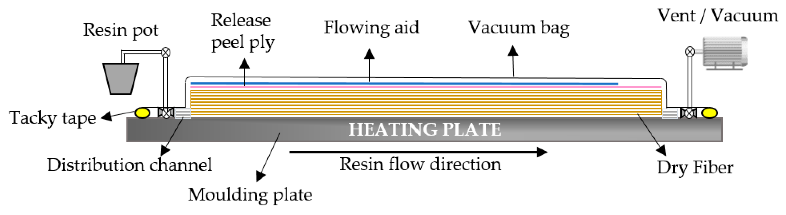
The reinforcement plies were cut to dimensions of 550 mm × 350 mm using a digital cutter system. As the natural fibers are hydrophilic, the reinforcement plies were subjected to drying in a conventional oven (Model FDL 115, Binder GmbH, Tuttlingen, Germany) at 120 °C for 30 min before composite fabrication.

2.3. Manufacturing

The composite laminates were fabricated using the Vacuum Assisted Resin Infusion (VARI) method, employing a single-sided rigid mold and vacuum bagging to apply vacuum pressure. The schematic illustration of the VARI composite manufacturing process is provided in Figure 2.
In this study, two composite materials are processed and investigated, Flax-Bio-based Epoxy Composite (FBEC) and Flax-Bio-based Vitrimer Composite (FBVC). To produce the FBEC laminates, dry preforms were laid on a mold with a distribution channel previously treated with a release agent. A release peel ply was positioned over the preform to facilitate separation during vacuum bagging, while a resin distribution media was employed to enhance resin flow velocity. The mold was sealed with vacuum bag and sealant tape, and consolidation was achieved by applying vacuum pressure through the vent tube. The inlet tube was secured, and the mold temperature was set to 60 °C with a vacuum pressure of −0.97 bar. Before infusion, a vacuum drop test was conducted on the layup to detect any bag leakage. The resin-hardener mixture was degassed under vacuum to eliminate air bubbles. Infusion took place by creating a differential pressure between the vent and inlet. Upon complete infusion, both the inlet and vent were clamped, maintaining pressure until the resin cured for 180 min. Subsequently, the mold was cooled to room temperature, and the composite panel was demolded.
As for the FBVC laminate, the manufacturing process followed a similar sequence, involving fabric laying and vacuum bagging. However, due to the crystalline nature of both the hardener and catalyst, the resin-hardener mixture was slightly modified from the previous mixture. Initially, the ELSO was preheated to 80 °C, followed by the addition of the catalyst. The ELSO/TBD mixture was degassed, and the appropriate amounts of glutaric anhydride were then added. The resin mixture was stirred with a magnetic stirrer while being heated at 80 °C. Once homogenized, the mixture underwent degassing. During resin infusion, the mold temperature was set to 80 °C, and a vacuum pressure of −0.97 bar was maintained. After complete infusion, both the inlet and vent were clamped to sustain pressure, and the mold temperature was raised to 120 °C for a 20-h curing cycle.

2.4. Specimen Preparation

The composite laminates were produced with a nominal thickness of 4.5 mm. Specimens, measuring 150 mm × 100 mm, were precisely cut from both FBEC and FBVC laminates. The size was selected in accordance with the standards for drop impact testing and compression after impact, as outlined in ASTM D7136 [47] and ASTM D7137 [48]. As a result, 18 specimens were obtained for each set of FBEC and FBVC plates, respectively.

3. Repair and Test Methodology
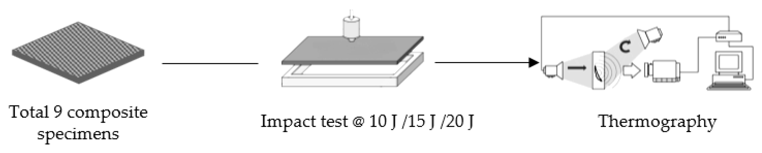
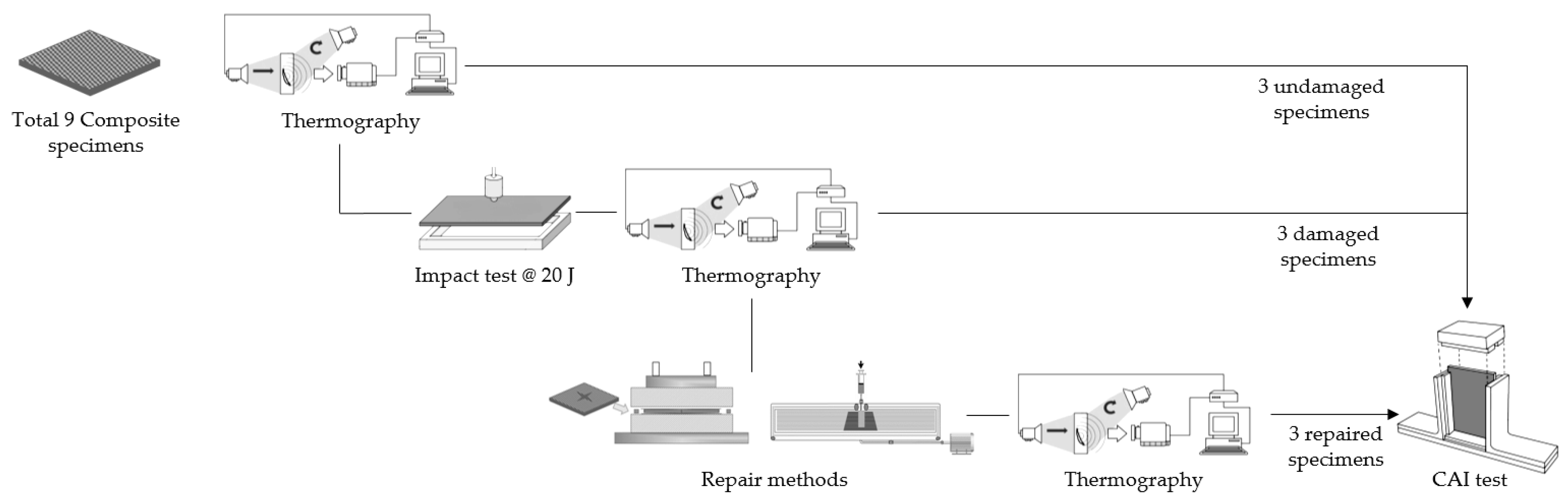
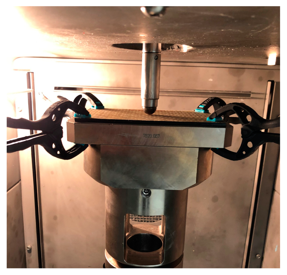
An outline of the impact testing is shown schematically in Figure 3, and a comprehensive overview of the repair activities is depicted in Figure 4 for each set of FBEC and FBVC plates, respectively.

3.1. Impact Test

A CEAST 9350 instrumented drop tower (Instron, Norwood, MA, USA) was utilized for the impact testing of composite laminates according to the standard ASTM D7136 [47]. A hemispherical impactor with a diameter of 20 mm, equipped with a force sensor, was employed. Throughout the test campaign, the drop height was maintained at 200 mm, and the velocity at 1.98 m/s remained constant. Each specimen was carefully positioned within the impact support fixture and securely fastened at the four corners using identical clamps, as depicted in Figure 5. The impact energy levels were varied by adjusting weights, resulting in energy settings of 10 J, 15 J, and 20 J, respectively. For each energy level, three specimens of FBEC and FBVC, respectively, were subjected to impact testing.
In order to address the repair, it was determined that all selected specimens would be exposed to a uniform level of damage. An impact energy of 20 J was specifically chosen for this purpose. Impact testing at the chosen energy level was conducted on six specimens of FBEC and FBVC, respectively.

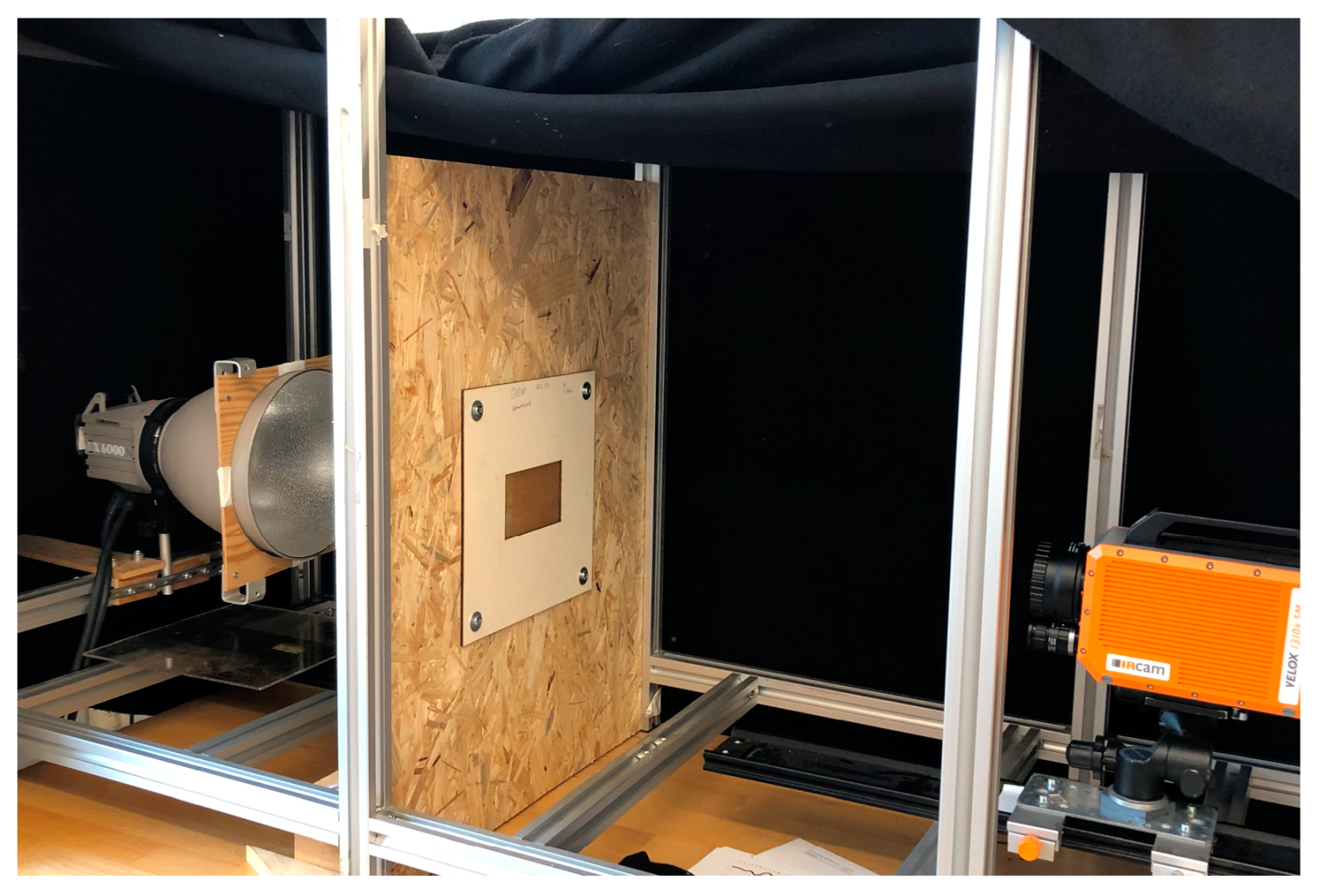
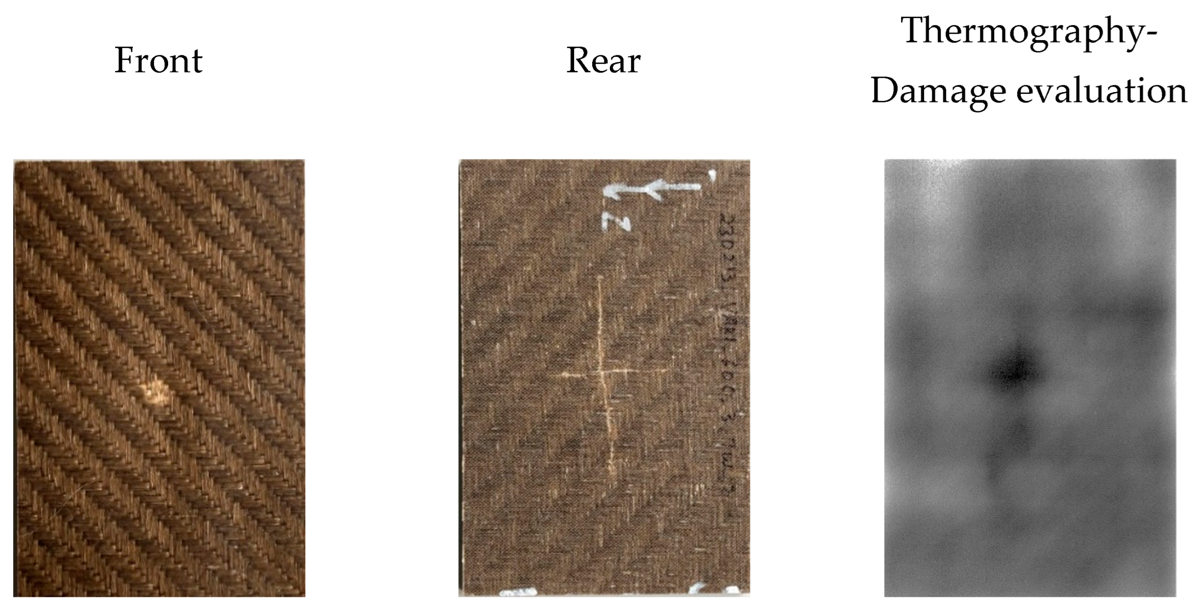
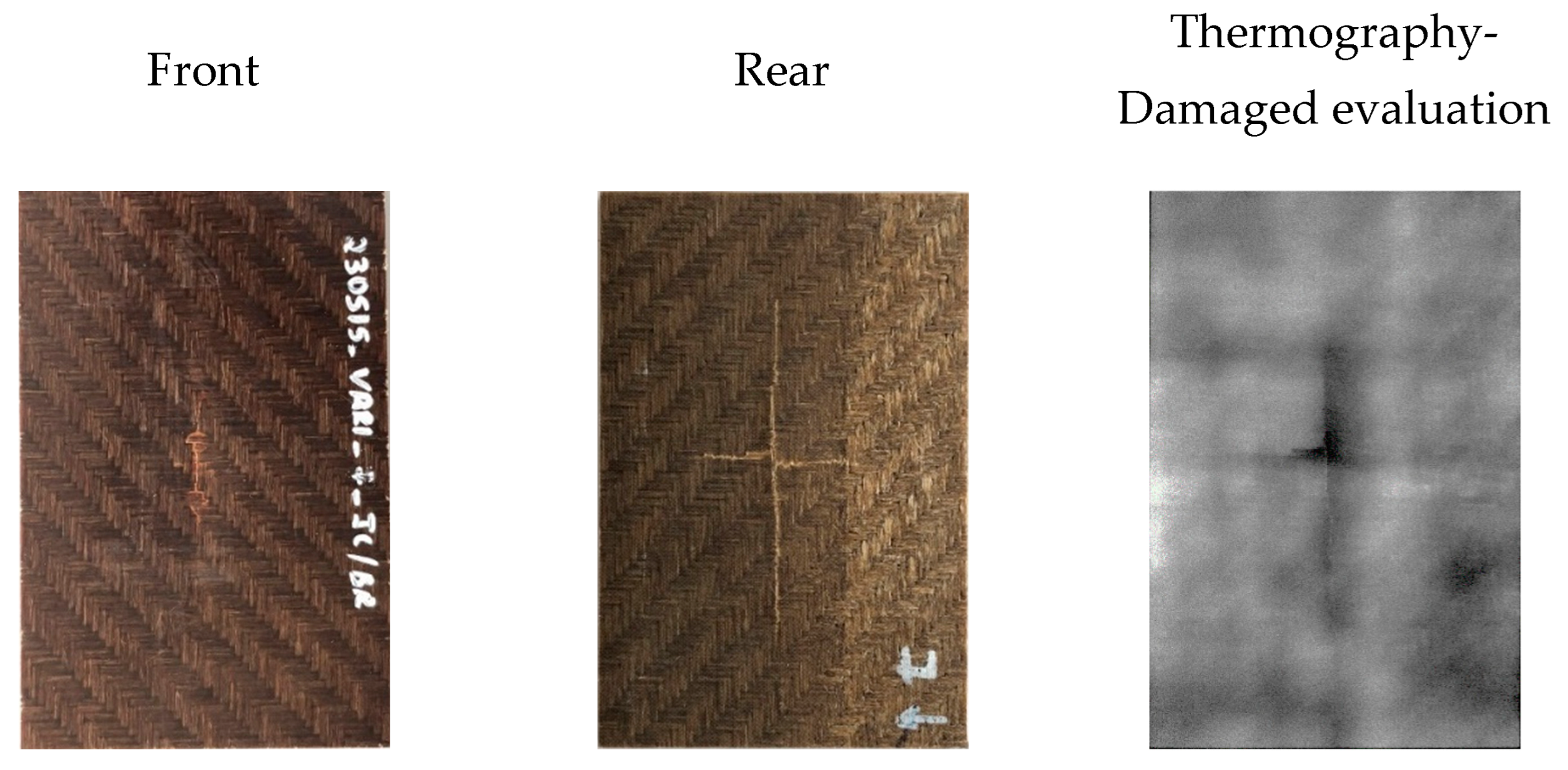
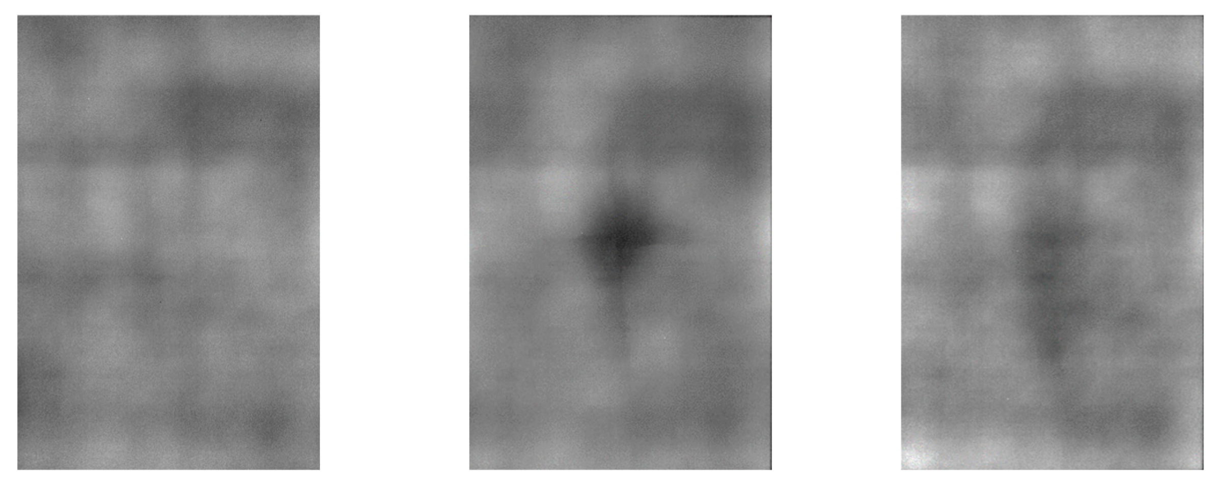
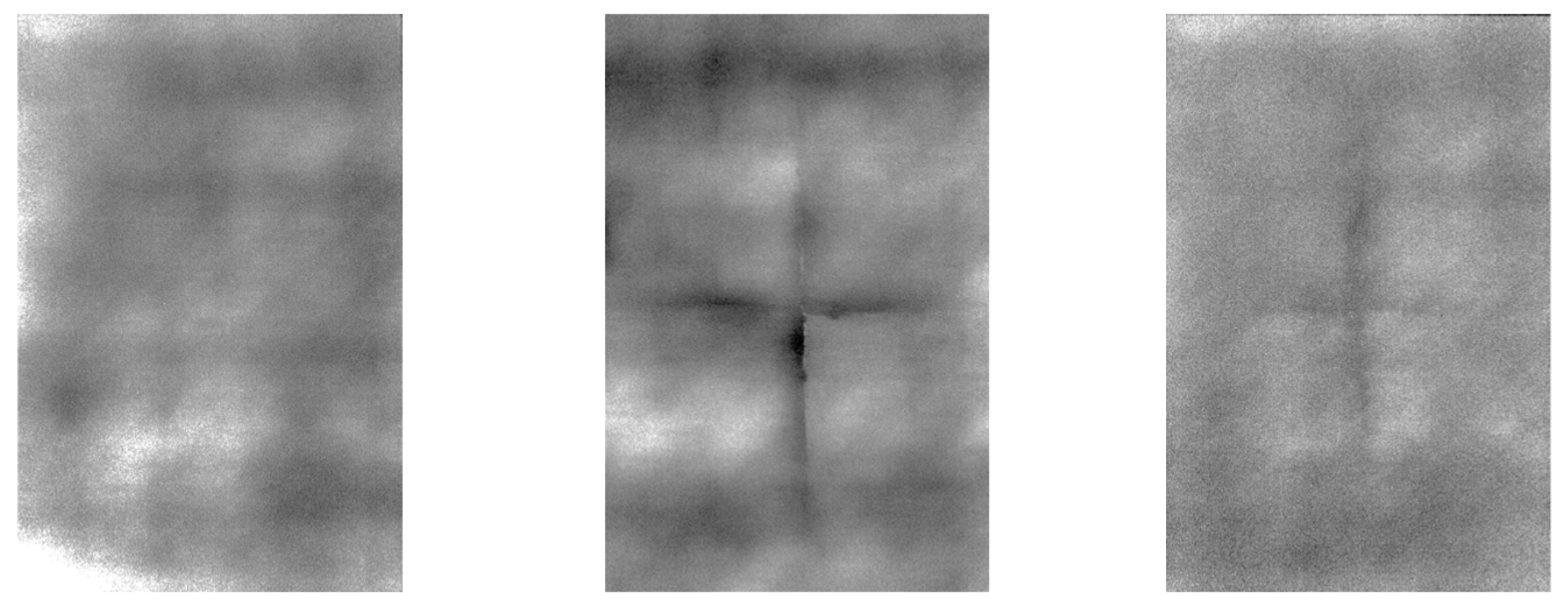
3.2. Active Thermography

Following the impact tests, non-destructive testing was performed using active infrared thermography [49,50] to analyze the damage progression in the specimens.
Infrared thermography utilizes a heat source, represented by a flash lamp, along with an IR camera to generate thermal images of the specimens. It offers qualitative and quantitative analysis of defects by utilizing thermal diffusivity data from the damaged zone. Detection of defects through flash thermography relies on the surface temperature’s time-dependent response to a thermal impulse. Through a transmission configuration, IR thermography detects defects in the specimens using the flash lamp positioned 360 mm away from the specimen, and the IR camera placed at the distance of 630 mm from the specimens, as depicted in Figure 6. Images are captured over a 100 s interval at a frequency of 5 Hz. Subsequently, all images undergo normalization using an averaging code in MATLAB (Version: 9.12), with reference to the maximum temperature.

3.3. Repair Methods

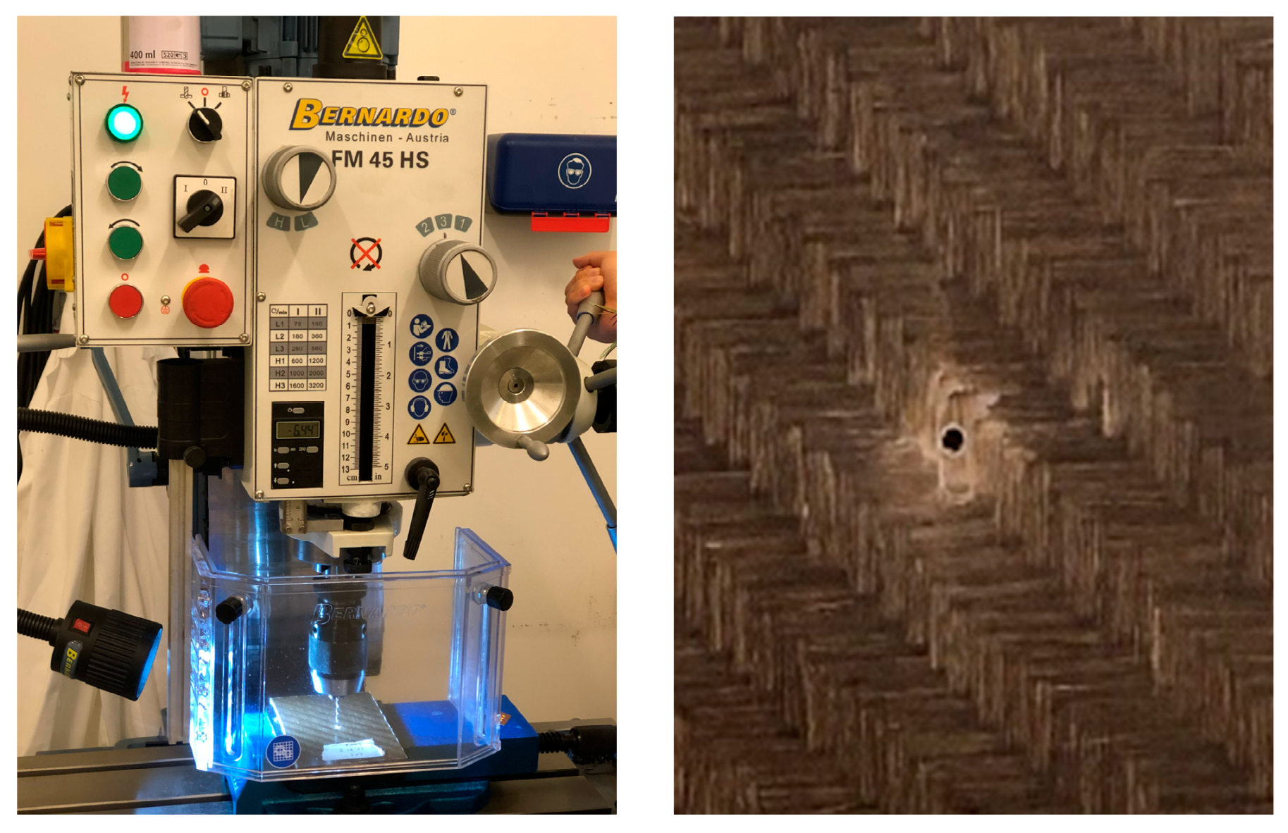
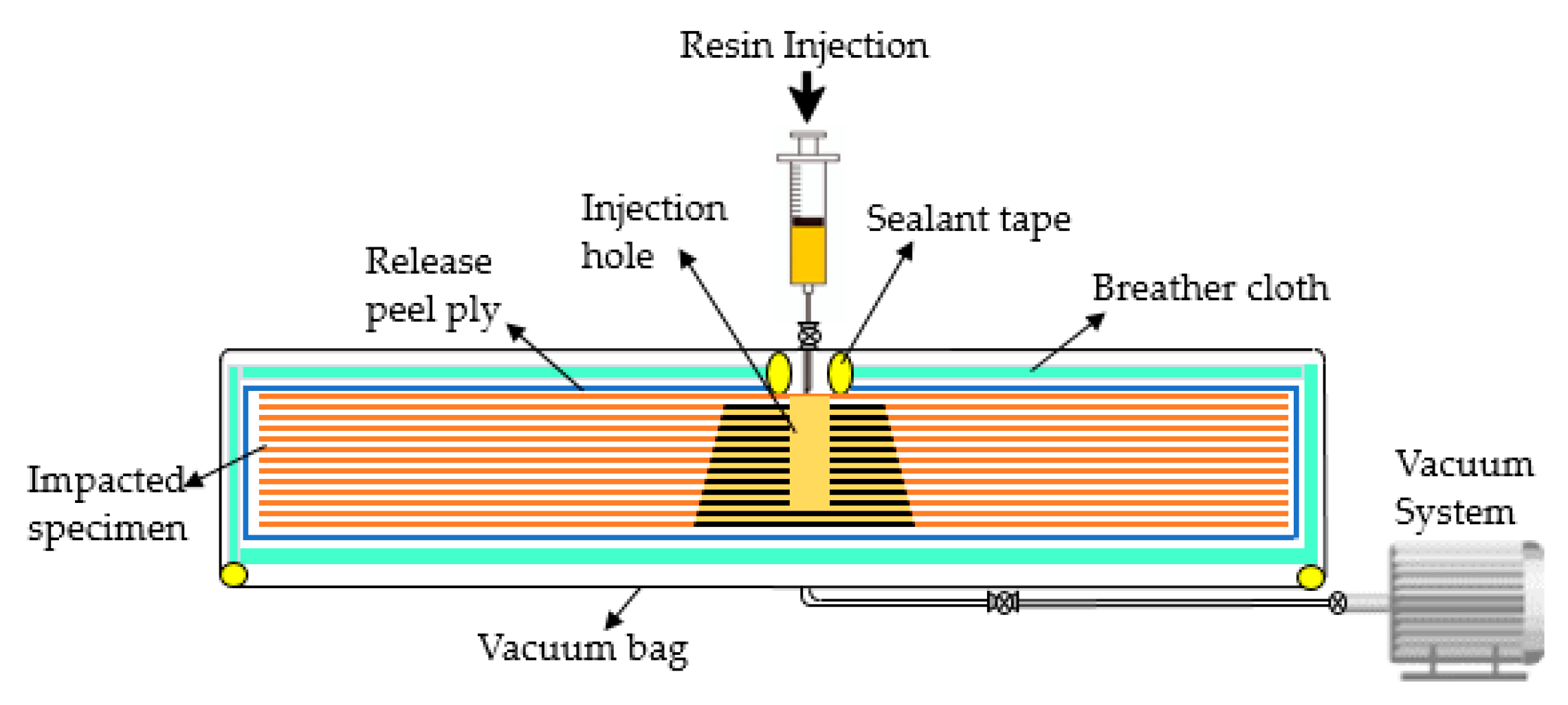
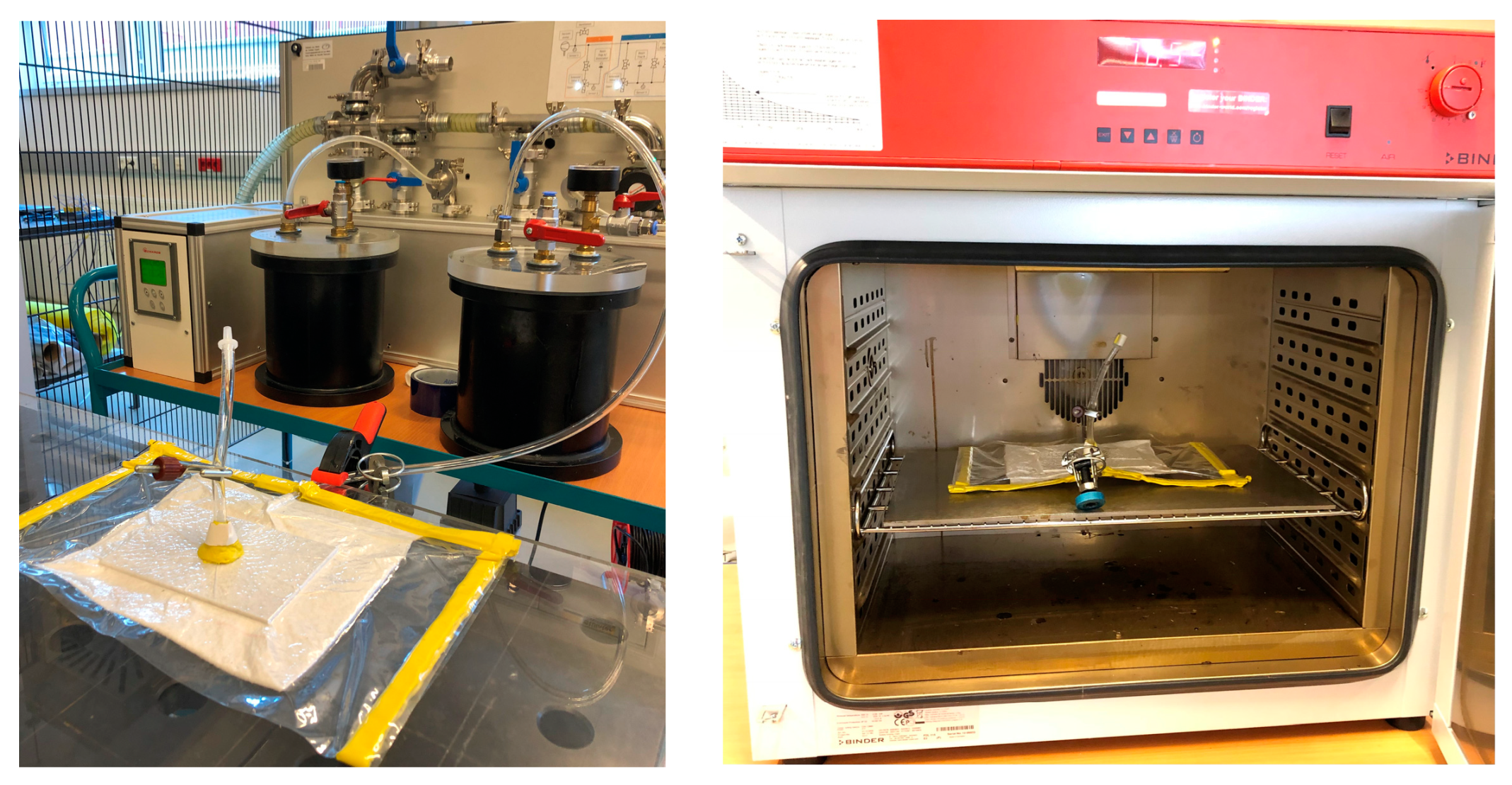
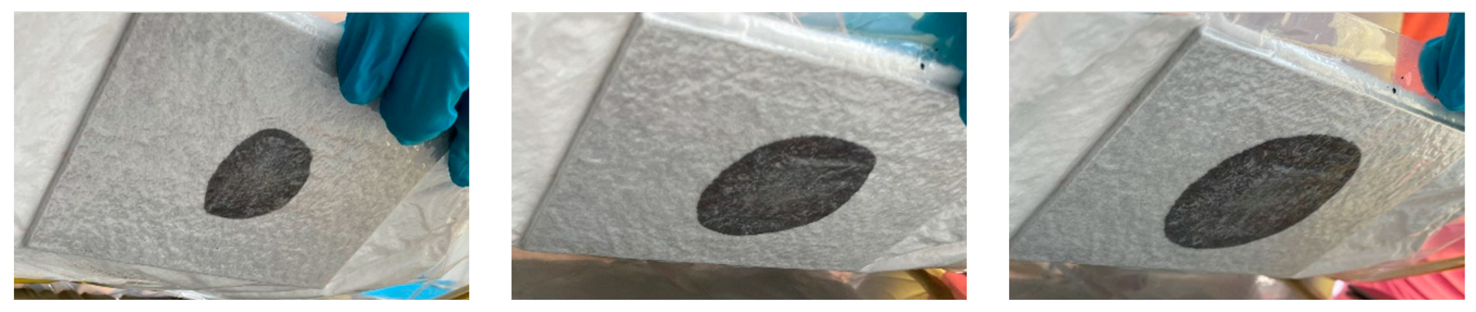
3.3.1. Resin Reinfiltration Method

The resin reinfiltration method involves drilling and reintroducing a compatible resin into the damaged zone to fill cracks and delamination, followed by heating the specimen to cure the resin in place. The successful repair of damaged specimens depends on selecting an appropriate resin, primarily based on its viscosity. However, resin reinfiltration repairs are often constrained due to potential harm caused by drilling, as reported in prior studies [51,52]. Concerns arise regarding further damage during the drilling of vent holes. It was observed that the vent holes remained unfilled by the resin. This is attributed to the uneven damage and blocked nature of internal delamination, possibly influencing resin flow towards the vent hole path. Consequently, a vent hole-less approach will be investigated in this study.
A resin injection hole is added to the FBEC specimen. Instead of vent holes, a vacuum is used from the rear side to displace air and inject resin. Microcrack networks and delamination provide pathways for resin flow during vacuum operation. A High-Speed Steel (HSS) twist drill with a 2 mm diameter is used for drilling. The drilling is carried out with a press table drill, the FM 45 HS model from Bernardo (Linz, Austria), as depicted in Figure 7. The drilling operates at 2000 rpm rotational speed and 0.05 mm/rev feed rate. The drilling depth is set at 75% of the specimen’s total thickness.
Figure 8 illustrates the resin reinfiltration approach, where the impacted specimen is enveloped by a release peel ply and a breather cloth, creating a channel for displaced air and resin to flow uniformly from the rear side. A vacuum bag is carefully applied to establish a controlled environment, while sealant tape ensures proper sealing and resin introduction solely through the designated injection hole. Inlet and outlet tubes, along with valves, are appropriately positioned, and the vacuum system is activated to detect and resolve any air leaks through adjustments to the sealant tape. The injected resin maintains the same resin (Epinal b.poxy IR78.31) to hardener (Epinal IH77.11) weight ratio as the infusion resin (100:25) and is prepared in a sufficient quantity to fill a 20 mL syringe. The syringe remains positioned atop the damaged specimen through the inlet valve throughout injection phases. Upon activating the vacuum system and addressing any air leaks, the injection process commences by opening the inlet valves. The resin flows into the injection hole in the damaged zone, aided by the vacuum displacement. Maintaining a pressure of ~1 bar from the syringe ensures effective resin injection into the damaged area.
Following a duration of 15 min, the injection procedure was halted by shutting the inlet and outlet valves, as illustrated in Figure 9. Then, the syringe was removed, and the outlet tube was detached. The entire assembly was transferred to an oven set at 80 °C, where it underwent curing for 1 h. Upon completion of the curing phase, the consumables—namely, the vacuum bag, release peel ply, and breather cloth—were delicately removed from the repaired specimen. The resin infusion effectively filled the voids created by the drilling process, and any remaining traces of sealant tape were meticulously eliminated from the surface of the repaired specimen.

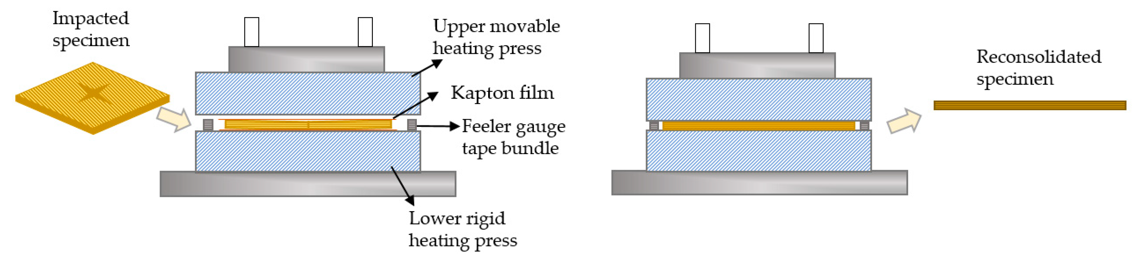
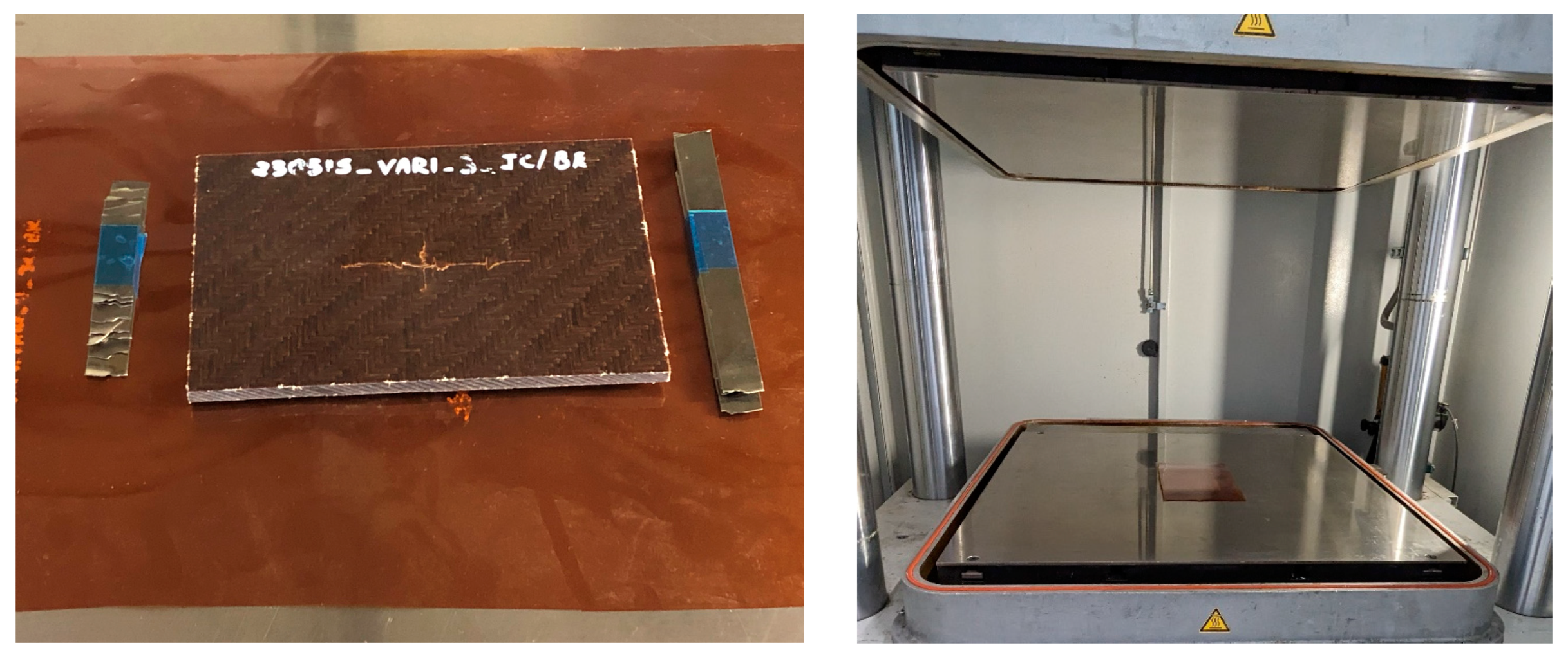
3.3.2. Reconsolidation (Self-Healing) Method

In composite materials, prolonged degradation leads to microcrack formation and eventual failure [53]. Repair is necessary to enhance reliability and durability [54,55]. Self-healing mechanisms can restore structural integrity during failure but may require external triggering. To address damage, like matrix cracking and delamination in FBVC specimens, a reconsolidation approach via thermal triggering is required. This approach allows the material to reach the topology freezing transition temperature (Tv), typically above the glass-transition temperature (Tg). This transition makes the rigid polymer rubbery, reducing the elastic modulus and enabling self-repair in a structural context.
In this investigation concerning the FBVC specimen, the expected vitrimer transition temperature is 160 °C, as referenced in [56], and maintaining the resin above its Tg for at least 3 h is crucial for alleviating internal stresses within the material and encouraging the development of vitrimeric characteristics. The reconsolidation repair approach employed in this study is depicted in Figure 10. The impacted specimen is positioned on a press WPK 3500 S from Wickert (Landau, Germany), preheated to 160 °C. To prevent the specimen from adhering to the press surface, Kapton® Polyimide film from DuPont™, Wilmington, DE, USA is strategically positioned both above and below it. Before commencing the repair procedure, the thickness of each specimen is precisely measured. Subsequently, a bundle of feeler gauge tape, matching the original thickness of the specimen, is strategically placed alongside it, as depicted in Figure 10. This strategic placement ensures that the flexible specimen maintains its original thickness, preventing excessive compression during pressing. This prevents ply displacement and misalignment in the composite laminate, preserving its structural integrity during heating and repair.
Upon reaching a temperature of 160 °C on both sides of the press, a careful arrangement is made with the polyimide film, specimen, and bundles of feeler gauge tape, as illustrated in Figure 11. Subsequently, the press is gradually lowered until it contacts both sides of the specimen. The press is then gently brought down in a controlled manner to restore the specimen’s shape, which had been deformed due to the impact. As the press approaches the point where the feeler tape bundles naturally create a stopping point on both sides, a consistent compressive load of approximately 5 kN is maintained. This load persists throughout the entire reconsolidation process, spanning a duration of 240 min for each individual specimen. After the 240 min interval has elapsed, the press is carefully disengaged, and the specimen is subsequently extracted.

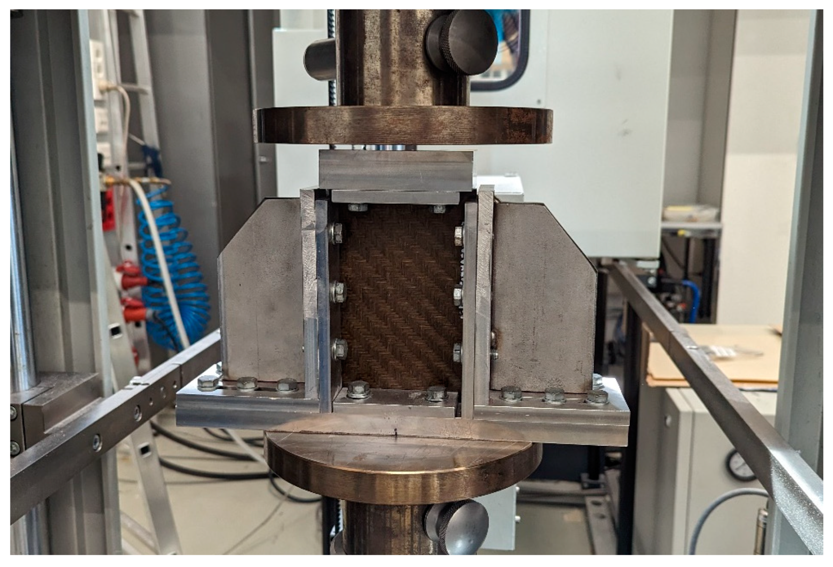
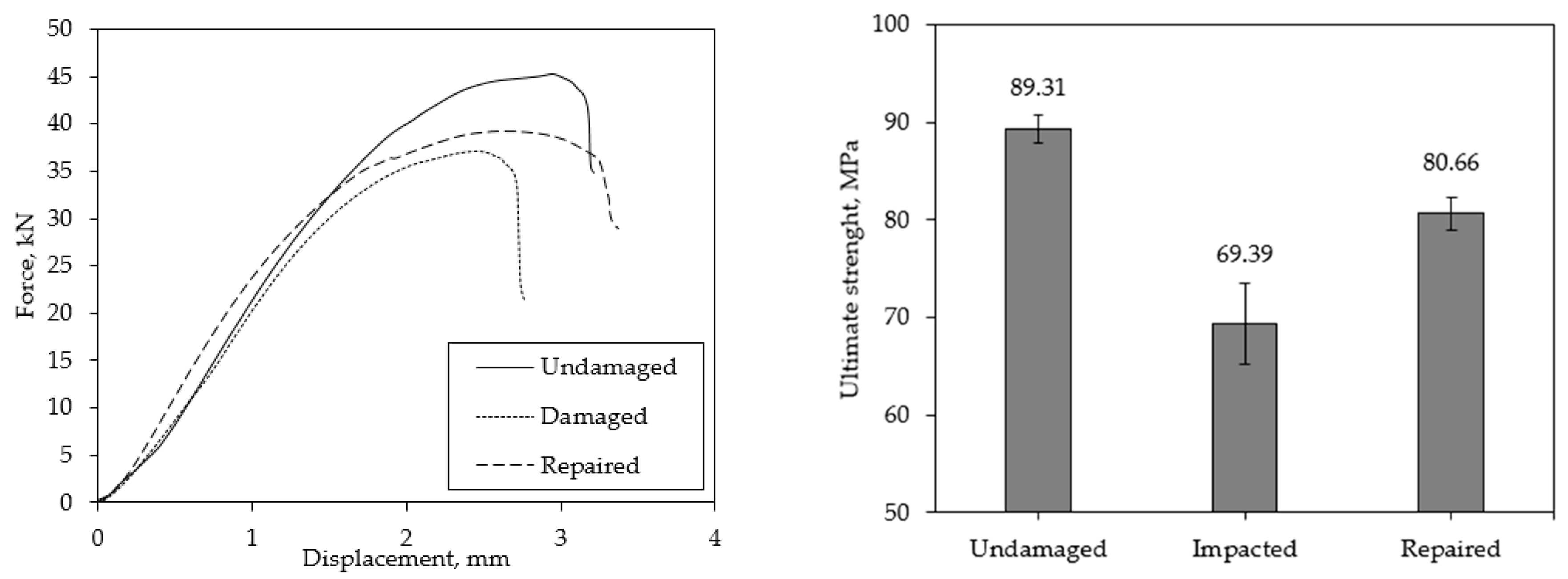
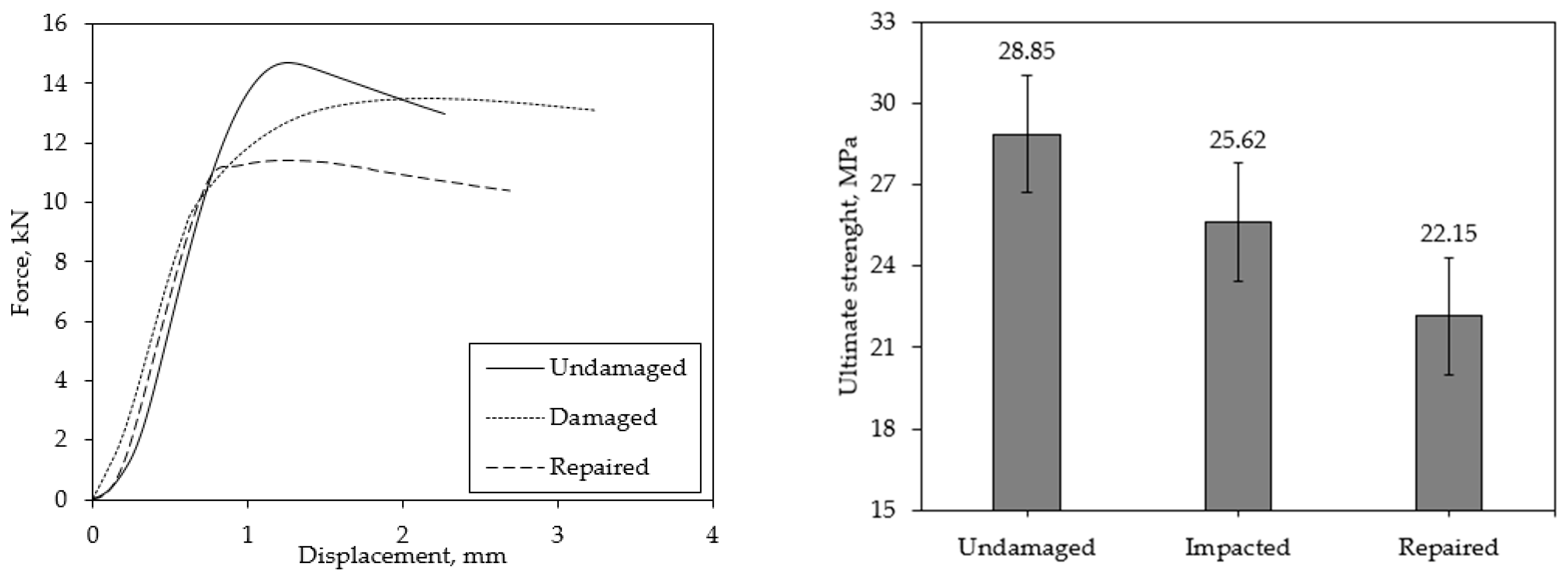
3.4. Compression after Impact Testing (CAI)

In order to evaluate the effectiveness of repairs conducted on impacted specimens and to perform a comparative analysis, the specimens undergo testing to assess their damage tolerance under compressive load. Compressive After Impact (CAI) testing is a common method used to characterize the impact performance of composites by measuring the degradation in compressive strength following prior impact loading [57]. Typically, CAI testing is not conducted on undamaged specimens due to inadequate constraint of specimen edges in the test fixture, leading to inappropriate failures at these locations (crushing). However, in this study, CAI tests following standards ASTM 7137 [48] were performed on undamaged, damaged, and repaired specimens to offer a relative comparison of repair competence using a standardized test method.
The specimen was placed in the CAI fixture, as illustrated in Figure 12. The fixture supports the specimen along all four edges, with adjustability according to the specimen’s thickness. The top (loading) plate, not directly attached to the lower portion of the fixture, slides over the specimen’s top edge to provide simple support. Short side rails ensured a gap between them and the top plate during compression testing. The assembled fixture, with the specimen installed, is positioned unconstrained on the flat base of universal testing machine Z250, Zwick Roell (Zwick GmbH and Co., Ulm, Germany) and compressive loading is applied directly to the top plate by a platen in the crosshead of the testing machine. Tests are conducted at a crosshead speed of 0.5 mm/min until a sudden drop in the load–displacement curve is recorded.
The compressive strength, also known as ultimate strength, measured in MPa, as defined by the standard ASTM D7137 [48], is obtained through Equation (1):
σ C = F A ,
where F is the resulting peak load, and A refers to the cross section of the composite.

4. Results and Discussions

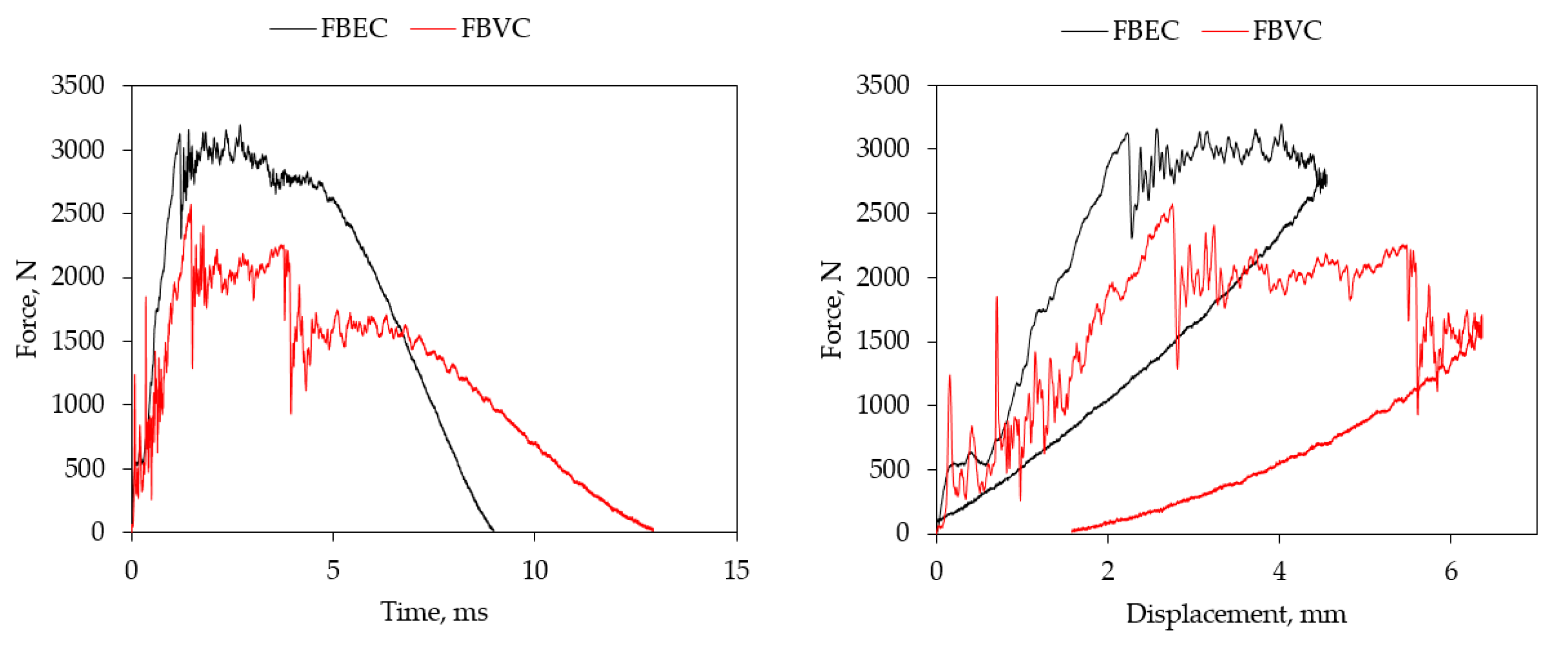
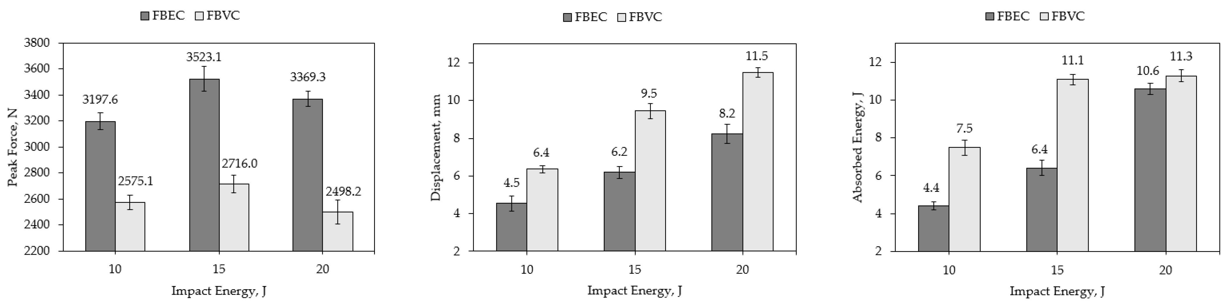
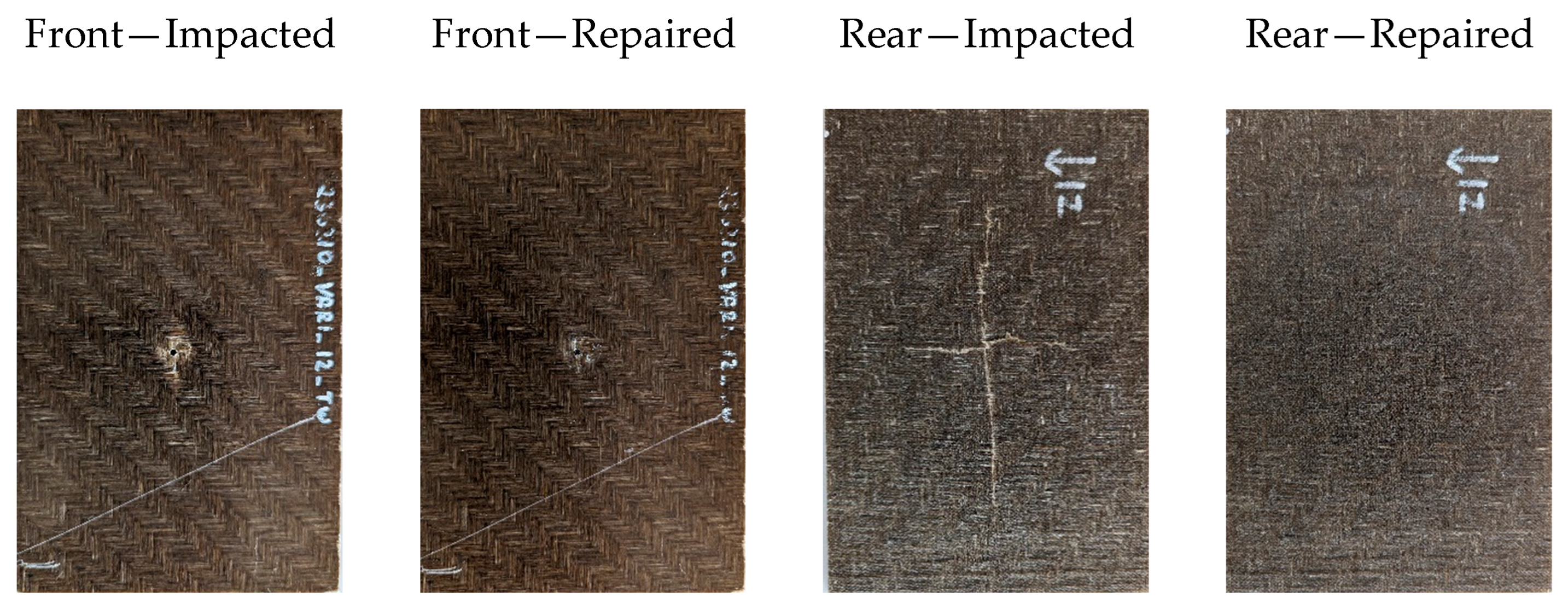
4.1. Impact Response
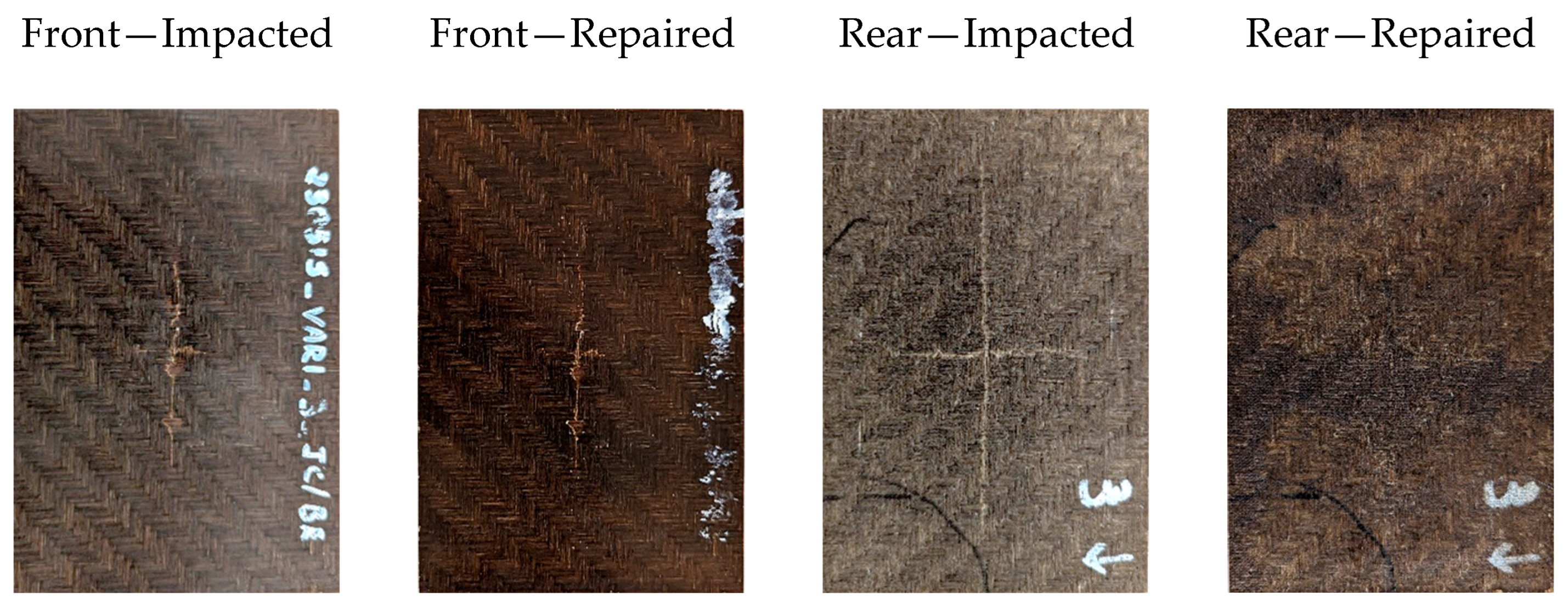
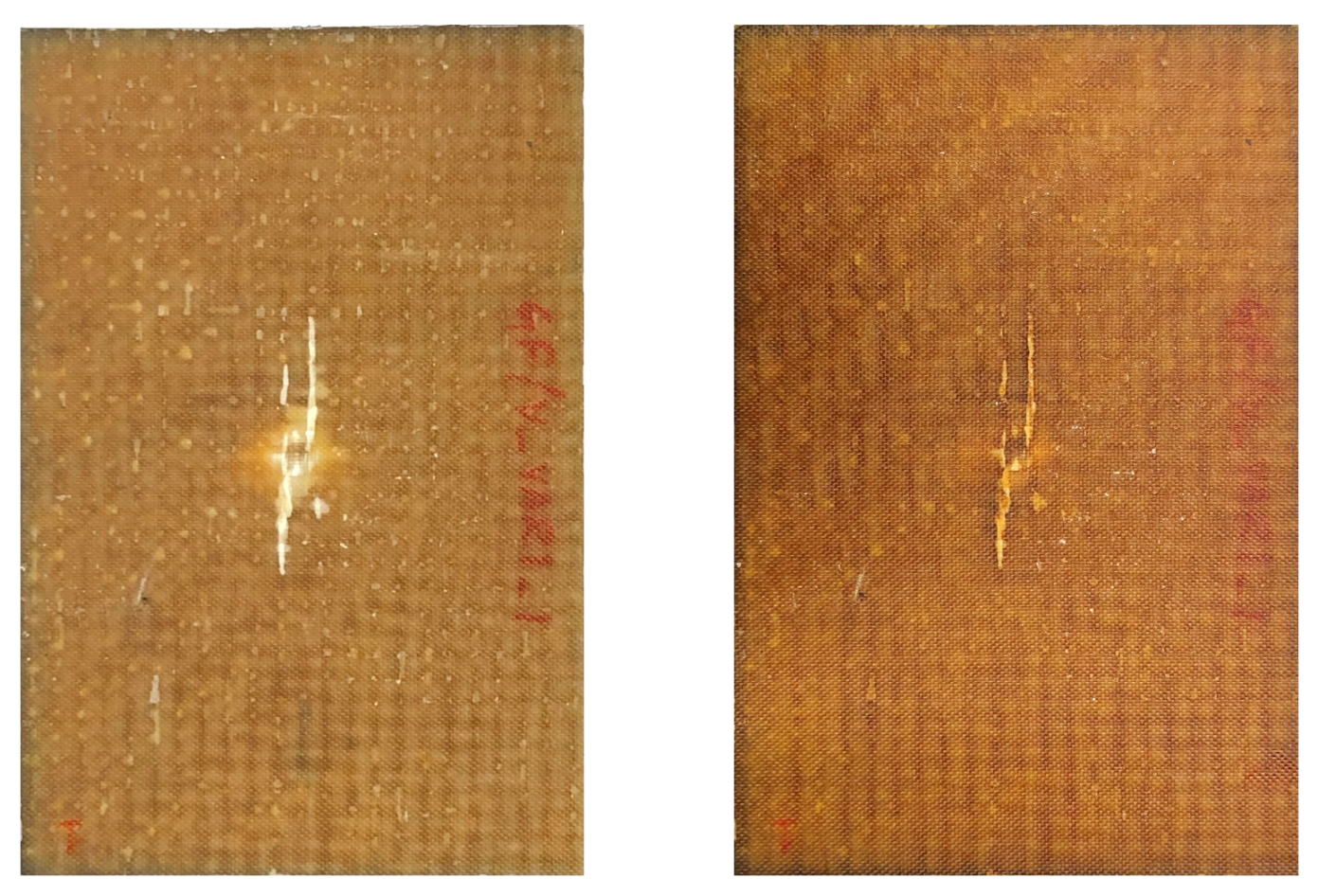
The sensor instrumentation integrated into the drop tower enables the measurement of various impact-related parameters, including contact force, duration, and displacement records of the impactor. Figure 13 displays distinct graphs derived from this dataset: (a) force versus time and (b) force versus displacement at an energy level of 10 J for both FBEC and FBVC, respectively. Owing to the similarity in trends observed at energy levels 15 J and 20 J, the graphical presentation for these levels is excluded.
Figure 13 (left) depicts force versus time curves that exhibit an asymmetric bell shape, corresponding to the loading and unloading phases of the specimen. A significant oscillation is seen, which is attributed to the elastic wave response and vibrations within the impact system elements (samples, impactor, and boundary conditions) [58]. The force response demonstrates non-linear behavior until it reaches the peak force, which represents the critical force associated with the initial significant drop. This drop occurs due to local internal damage, such as delamination, matrix cracking or fiber-matrix failure within the composite. Following the critical force, an unloading phase ensues, attributable to rebound or composite failure.
The force–displacement response during an impact event offers valuable insight into damage progression within the composite specimen. In all impact cases, specimens experienced deformation upon contact with the impactor but rebounded without severe perforation. Displacement values were calculated using force measurements representing the deformation of the impacted surface and the movement of the impactor. Figure 13 (right) illustrates force–displacement curves showing partial rebounding corresponding to loading and unloading conditions, respectively. The ascending part also provides information about the impact stiffness of the specimen. Peak deformation in the specimens corresponds to the maximum displacement value obtained from the force–displacement graph. Despite noise, the graph exhibits two or more points of zero slope, possibly indicative of cracks, tears, or failure of individual components in the specimen.
Furthermore, Table 1 provides the averaged peak force, absorbed energy, and displacement corresponding to various impact energy levels for both FBEC and FBVC, respectively. Figure 14 (left) shows the peak force at different energy levels. A notable observation is that, across all three energy levels (10 J, 15 J, and 20 J), the peak force of the FBEC surpasses that of the FBVC by 21%, 25%, and 29% at 10 J, 15 J, and 20 J, respectively. However, the contact time is remarkably greater for the FBVC than for the FBEC, by approximately 38%. This difference can be attributed to the inherent brittleness of the FBEC. Moreover, contact time increases with the applied energy and depends on the matrix utilized. Hence, as the energy level increases, the damage progresses, resulting in a corresponding increase in contact time.
Figure 14 (mid) graphically represents the averaged displacement at various energy levels. It is evident that the peak displacement of the FBVC is higher compared to the FBEC. Indeed, a permanent deformation after impact is observed at 15 J and 20 J, which could be attributed to the nature of the vitrimeric matrix. Notably, the FBVC samples exhibit substantially higher displacement values corresponding to 34%, 42%, and 33% at 10 J, 15 J, and 20 J, respectively, than the FBEC, as indicated in Table 1. This difference indicating the enhanced ductile characteristics of the vitrimer sample. A similar trend is observed for the evolution of the maximum displacement as the applied impact energy increases. The averaged absorbed energy is presented graphically in Figure 14 (right). A significant increase in absorbed energy is observed for the FBVC compared to FBEC. The difference between the absorbed energy of the FBVC and the FBEC corresponds to 52%, 53%, and 6.3% for the impacted energies at 10 J, 15 J, and 20 J, respectively.
Figure 15 offers a comprehensive comparison between visual inspection and thermography inspection of the rear side of impacted FBEC. It is apparent from the images that fiber breakage occurs in composites across all impact energy levels. On the rear side of the impacted specimens, observable cracks emerge. The size of these cracks amplifies with higher impact energy levels, eventually forming a distinct cross-shaped pattern. This phenomenon can be attributed to the balanced structure of the woven flax fabric, which distributes the impact forces and results in the formation of characteristic damage patterns. However, upon observing the thermographic images, it becomes evident that a significant elevation in surface temperature above the impacted zone occurs. This increase was attributed to the impedance encountered as heat flowed through the delaminated layers, with the damage mechanism intensifying along with an increase in the impact energy level. The thermographic analysis unveils irregularly shaped damage concentrated at the center of the impact zone.
A detailed comparison between visual inspection and thermography of impacted specimens of FBVC is shown in Figure 16. At lower impact energy levels, no visible damage or indentation is observed on the front side of the specimen. However, a crack is observed forming a cross-shaped pattern. At higher energy levels, visible damage is observed on the front side of the specimens resulting in significant deformation. Thermography analysis clearly shows the formation of a dominant cross-shaped fiber breakage crack on the rear side of the specimen, signifying internal damage that follows along the fiber.

4.2. Repair

4.2.1. Resin Reinfiltration Method

Figure 17 visually highlights a significant event during the resin reinfiltration process. Over a span of 10 min, it becomes apparent that resin continuously flows through the injection hole into the interior of the specimen, extending towards the rear side. The assistance provided by the vacuum system is crucial in facilitating this flow, with the volume of resin still increasing. This observation emphasizes the effectiveness of the reinfiltration process in delivering resin to the damaged area within the specimen. The dynamic representation depicted in the figure captures the ongoing flow, illustrating the successful displacement of air and the consistent infiltration of resin, thereby contributing to the repair of the impacted region.
The qualitative assessment of the repair process was conducted using non-destructive methods, employing the flash thermography technique. Across all specimens, it was evident that both the impact zone and its surroundings were sufficiently infiltrated with resin, resulting in a more uniform appearance in the repaired thermographic images, as depicted in Figure 18. This uniformity in the thermographic appearance indicates that the repair method performed as intended, effectively due to resin infiltrated into the delamination and cracks of the composite specimens.
Moreover, considering the aesthetic transformation of the restored composite, both before and after the repair, Figure 19 offers a direct comparison, presenting the same specimen previously identified as the repaired one. Both the front and rear sides of the specimen are displayed. While the front section of the plate remains largely unchanged, a noticeable transformation is observed on the rear side. Upon closer examination, it becomes evident that the injected resin has created pathways through the impacted zone, radiating from the center of the specimen towards the outer regions. This radial resin flow, upon the completion of the injection process, covered a radius of approximately 45 mm. This resulting resin distribution effectively concealed the cross-shaped crack that had developed in a layer of the composite, along with the adjacent matrix, subsequent to the impact event. This visual representation is indeed remarkable, as the repair process not only restored a portion of the composite’s original strength but also effectively concealed the aesthetic imperfection.
Figure 20 illustrates load–displacement graphs and the CAI compression strength of representative pristine, damaged, and repaired FBEC specimens. All specimens exhibited non-linear behavior before experiencing sudden failure. However, damaged specimens demonstrated a gradual decrease in load, resulting in failure at 77.6% of the ultimate compressive strength of undamaged specimens. In contrast, repaired specimens experienced a significant load decrease at the point of failure, similar to undamaged specimens. Notably, repaired specimens retained 90.3% of the ultimate compressive strength observed in undamaged specimens.
Undamaged specimens exhibited failure at the CAI fixture loading points, similar to the finding in [59]. This is a common occurrence in unnotched/undamaged composite compression specimens. Typically, failure reveals as crushing at the top contact surface or buckling in the free-length between the contact surface due to the absence of significant stress concentrations in the specimen. Consequently, failure initiates at minor stress concentrations created by the test fixture, specifically at the top of the plates supporting the specimen sides. In contrast, both damaged and repaired specimens experienced failure through the damage zone, as significant stress concentrations are present at this location due to the impact.

4.2.2. Reconsolidation (Self-Healing) Method

The reconsolidation repair process was qualitatively assessed through the application of flash thermography. Across all specimens, it was noted that reconsolidation resulted in a more consistent appearance in the repaired specimens, as depicted in Figure 21. Despite the presence of distinct cross-section marks stemming from fiber breakage caused by the impact, the repair method effectively addressed matrix cracks and delamination through pressure and high temperature, fulfilling its intended purpose. The presence of bright white spots near the edges of the specimen in the thermograph images can be attributed to an imperfect fit between the specimen holder and the specimen during the thermography procedure. This issue arises due to the potential for light from the flash lamp to leak around the holder in case it fails to conform securely to the shape of the specimen.
Concerning the visual alteration of the restored composite, both prior to and following the repair, Figure 22 facilitates a thorough comparison. The specimen is presented from both its frontal and rear aspects. While the front section of the specimen undergoes minimal change, a prominent transformation is evident on the rear side, effectively sealing the cracks displayed in the distinct cross pattern resulting from the impact test. Furthermore, there is a noticeable shift towards darker coloration observed.
Figure 23 illustrates load–displacement graphs along with the CAI compression strength for representative pristine, damaged, and repaired FBVC specimens. Every specimen demonstrates non-linear behavior. Notably, the load applied to the repaired specimens is considerably lower than that of the damaged specimens. Specifically, the ultimate compressive strength of damaged specimens decreases to 88.7% compared to undamaged specimens, whereas the ultimate compressive strength of repaired specimens drops to 76.7% when compared to undamaged specimens. Undamaged specimens experience failure characterized by crushing at the top contact surface or buckling in the free-length between the contact surface. In contrast, both damaged and repaired specimens fail due to the opening of cracks in the damage zone.
The outcomes of the reconsolidation repair for the FBVC differed significantly from the initial expectations. Figure 23 strongly suggests that the repair process not only failed to restore the mechanical properties of the damaged specimens but, instead, resulted in a decline. The ultimate load in compression after impact for the repaired specimens was lower than that of the corresponding damaged specimens, as evidenced by the presented data. This decline in the result can be attributed to the thermal degradation of flax fiber. Several studies in the literature have explored the thermal stability of flax composites [60,61,62]. Flax, being a natural fiber with a high cellulose content, typically contains around 80% cellulose, leading to increased flammability. Additionally, the mechanical properties of jute or flax undergo change at temperatures around 170 °C, as noted in [63]. Exposure of flax fibers to 120 °C results in moisture loss and wax degradation, as indicated by findings from reference [64]. Moreover, [65] indicates a decline in the storage modulus and an increase in the loss factor beyond 150 °C. Furthermore, [66] has reported that post-curing at high temperatures (150 °C) modifies flax composite mechanical properties, with decreased tensile strength and elongation at break, while the stabilized modulus remains relatively unchanged. The collective findings from prior research on flax suggest that the prolonged exposure of FBVC specimens to a temperature of 160 °C for 240 min during the reconsolidation process is likely to initiate thermal degradation reactions within the flax fibers, potentially weakening the overall composite structure.
The intricate nature of distinguishing whether observed outcomes are features of the matrix system or of thermal degradation of flax fiber complicates the validation of the reconsolidation repair method. To address this issue, a proposed solution involves substituting flax fiber with glass fibers. This substitution allows for a comprehensive assessment and comparison of the repair method’s efficacy, thereby enhancing the credibility of the findings. As a result, the manufacturing of glass-bio-based vitrimer composite (GBVC) laminate follows a similar procedure employed to the FBVC through the VARI method. A total of nine specimens are carefully cut from the laminates, with six subjected to rigorous impact testing at an energy level of 20 J. Subsequently, following the impact test, three of the specimens undergo a reconsolidation repair approach similar to that employed in FBVC. Further evaluations, specifically compression after impact tests, are then conducted on all nine specimens, aiming to thoroughly assess the effectiveness of the employed repair method.
Regarding the visual transformation of the restored GBVC, both before and after the repair, Figure 24 enables a thorough comparison. That the specimen undergoes a prominent transformation is evident. Additionally, there is a noticeable shift in coloration observed.
Figure 25 depicts load–displacement graphs and the CAI compression strength of representative pristine, damaged, and repaired GBVC specimens. All specimens exhibited non-linear behavior before experiencing sudden failure. The load applied to the repaired specimens surpasses that of the damaged specimens. Specifically, the ultimate compressive strength of damaged specimens drops to 73.1% compared to that of undamaged specimens, while the repaired specimens regained over 92.1% of its ultimate compressive strength when compared to undamaged specimens. The failure pattern resembles that of the FBVC.

5. Conclusions

While the adoption of bio-composites for the circular economy has been extensively explored, significant opportunities, such as repair and recycling, still need to be addressed. Therefore, this study offers preliminary insights into less invasive and more effective repair strategies using distinct bio-based matrices. The paper discusses two distinct repair approaches: (a) the resin infiltration repair method employing bio-based epoxy, and (b) the reconsolidation (self-healing) repair method using bio-based vitrimer matrix.
The study focuses on experimentally analyzing the low energy impact response of two distinct bio-based matrix composites. The impact characteristics (peak force, displacement, and absorbed energy) under different impact energy levels (10 J, 15 J, 20 J) are highlighted. The FBEC exhibits approximately 25% higher peak forces compared to the FBVC. However, the FBVC demonstrates higher contact time (approximately 38%), displacement (approximately 36%), and absorbed energy (approximately 50%) compared to the FBEC. Subsequently, specimens are impacted by a drop tower impact at an energy level of 20 J to investigate the repair approaches. For the resin reinfiltration, the repair efficiency evaluated by CAI test indicates successful restoration after repair, retaining 90% of its ultimate strength. Conversely, for the reconsolidation repair process, the FBVC not only failed to restore the mechanical properties of the damaged specimens but instead resulted in a decline. The ultimate load in CAI for the repaired specimens was lower than that of the corresponding damaged specimens. One proposed solution to address this issue involves replacing flax fiber with glass fibers, enabling a thorough assessment and comparison of the repair method’s effectiveness. The GBVC demonstrates successful repair after reconsolidation, retaining 92% of its ultimate strength. Confirmation of successful repair into the damage zone was obtained through flash thermography. Moreover, it is essential to identify an appropriate characterization method to quantitatively evaluate the effectiveness of healing. In order to thoroughly evaluate the repair capability of FBVC materials in future research, alternative factors, such as short-time exposure to elevated temperatures, could be considered to prevent thermal degradation resulting from the reconsolidation process. Furthermore, investigating alternative reconsolidation techniques could provide valuable insights into improving repair effectiveness and maintaining mechanical integrity.

Author Contributions

Conceptualization, B.R.; methodology, B.R.; validation, B.R.; formal analysis, B.R.; investigation, (processing and repair) B.R., (thermography) T.A.; resources, E.F.; data curation, B.R.; writing—original draft preparation, B.R.; writing—review and editing, M.F., E.F. and B.O.-T.; visualization, B.R., M.F., and E.F.; supervision, B.R.; project administration, E.F.; funding acquisition, E.F. All authors have read and agreed to the published version of the manuscript.

Funding

This research was funded in the framework of the program Project QB3R (project no. FO999889818) by the Austrian Ministry for Climate Action, Environment, Energy, Mobility, Innovation and Technology, within the framework of the FTI initiative Kreislaufwirtschaft 2021, which is administered by the Austria Research Promotion Agency (FFG).

Data Availability Statement

The data presented in this study are available on reasonable request from the corresponding author.

Acknowledgments

The authors extend gratitude to Ralf Schledjewski (R.S.) for conceptualization and funding acquisition. The author acknowledges Martina Stryzek for her initial investigation on vitrimers and Juan Cardenas Velasco for his assistance in conducting the repair methods. Special thanks are extended to Maria Gfrerrer for her support with the impact tests and the editing of the paper draft; these contributions are greatly appreciated and will be duly acknowledged.

Conflicts of Interest

The authors declare no conflicts of interest.

References

  1. Gurunathan, T.; Mohanty, S.; Nayak, S.K. A review of the recent developments in biocomposites based on natural fibres and their application perspectives. Compos. Part A Appl. Sci. Manuf. 2015, 77, 1–25. [Google Scholar] [CrossRef]
  2. Satyanarayana, K.G.; Arizaga, G.G.C.; Wypych, F. Biodegradable composites based on lignocellulosic fibers—An overview. Prog. Polym. Sci. 2009, 34, 982–1021. [Google Scholar] [CrossRef]
  3. Cheung, H.; Ho, M.; Lau, K.; Cardona, F.; Hui, D. Natural fibre-reinforced composites for bioengineering and environmental engineering applications. Compos. Part B Eng. 2009, 40, 655–663. [Google Scholar] [CrossRef]
  4. Gondaliya, K.; Alipoormazandarani, N.; Kleiman, M.; Foster, E.J. Sustainable compressed biocomposite: Review on development and novel approaches. Mater. Today Commun. 2023, 35, 105846. [Google Scholar] [CrossRef]
  5. Abdollahiparsa, H.; Shahmirzaloo, A.; Teuffel, P.; Blok, R. A review of recent developments in structural applications of natural fiber-Reinforced composites (NFRCs). Compos. Adv. Mater. 2023, 32, 1–18. [Google Scholar] [CrossRef]
  6. Panciroli, R.; Giannini, O. Comparing the impact resistance of flax/epoxy and glass/epoxy composites through experiments and numerical simulations. Compos. Struct. 2021, 264, 113750. [Google Scholar] [CrossRef]
  7. Sathishkumar, T.; Navaneethakrishnan, P.; Shankar, S.; Rajasekar, R.; Rajini, N. Characterization of natural fiber and composites—A review. J. Reinf. Plast. Compos. 2013, 32, 1457–1476. [Google Scholar] [CrossRef]
  8. Dittenber, D.B.; GangaRao, H.V.S. Critical review of recent publications on use of natural composites in infrastructure. Compos. Part A Appl. Sci. Manuf. 2012, 43, 1419–1429. [Google Scholar] [CrossRef]
  9. Vidal, J.; Ponce, D.; Mija, A.; Rymarczyk, M.; Castell, P. Sustainable Composites from Nature to Construction: Hemp and Linseed Reinforced Biocomposites Based on Bio-Based Epoxy Resins. Materials 2023, 16, 1283. [Google Scholar] [CrossRef]
  10. Khalid, M.Y.; Rashid, A.A.; Arif, Z.U.; Ahmed, W.; Arshad, H.; Zaidi, A.A. Natural fiber reinforced composites: Sustainable materials for emerging applications. Results Eng. 2021, 11, 100263. [Google Scholar] [CrossRef]
  11. Pickering, K.L.; Aruan-Efendy, M.G.; Le, T.M. A review of recent developments in natural fibre composites and their mechanical performance. Compos. Part A Appl. Sci. Manuf. 2016, 83, 98–112. [Google Scholar] [CrossRef]
  12. Yan, L.; Chouw, N.; Jayaraman, K. Flax fibre and its composites—A review. Compos. Part B Eng. 2014, 56, 296–317. [Google Scholar] [CrossRef]
  13. Memon, H.; Wei, Y.; Zhu, C. Recyclable and reformable epoxy resins based on dynamic covalent bonds—Present, past, and future. Polym. Test. 2022, 105, 107420. [Google Scholar] [CrossRef]
  14. Morici, E.; Dintcheva, N.T. Recycling of Thermoset Materials and Thermoset-Based Composites: Challenge and Opportunity. Polymers 2022, 14, 4153. [Google Scholar] [CrossRef] [PubMed]
  15. Lucherelli, M.A.; Duval, A.; Avérous, L. Biobased vitrimers: Towards sustainable and adaptable performing polymer materials. Prog. Polym. Sci. 2022, 127, 101515. [Google Scholar] [CrossRef]
  16. Zhen, X.; Cui, X.; Al-Haimi, A.A.N.M.; Wang, X.; Liang, H.; Xu, Z.; Wang, Z. Fully bio-based epoxy resins from lignin and epoxidized soybean oil: Rigid-flexible, tunable properties and high lignin content. Int. J. Biol. Macromol. 2024, 254 Pt 2, 127760. [Google Scholar] [CrossRef] [PubMed]
  17. Tiz, D.B.; Vicente, F.A.; Kroflič, A.; Likozar, B. Lignin-Based Covalent Adaptable Network Polymers—When Bio-Based Thermosets Meet Recyclable by Design. ACS Sustain. Chem. Eng. 2023, 11, 13836–13867. [Google Scholar] [CrossRef]
  18. Tang, R.; Xue, B.; Tan, J.; Guan, Y.; Wen, J.; Li, X.; Zhao, W. Regulating Lignin-Based Epoxy Vitrimer Performance by Fine-Tuning the Lignin Structure. ACS Appl. Polym. Mater. 2022, 4, 1117–1125. [Google Scholar] [CrossRef]
  19. Menager, C.; Guigo, N.; Vincent, L.; Sbirrazzuoli, N. Polymerization kinetic pathways of epoxidized linseed oil with aliphatic bio-based dicarboxylic acids. J. Polym. Sci. 2020, 58, 1717–1727. [Google Scholar] [CrossRef]
  20. Sangaletti, D.; Ceseracciu, L.; Marini, L.; Athanassiou, A.; Zych, A. Biobased boronic ester vitrimer resin from epoxidized linseed oil for recyclable carbon fiber composites. Resources. Conserv. Recycl. 2023, 198, 107205. [Google Scholar] [CrossRef]
  21. Monteserin, C.; Blanco, M.; Uranga, N.; Sanchez, J.; Laza, J.M.; Vilas, J.L.; Aranzabe, E. Sustainable biobased epoxy thermosets with covalent dynamic imine bonds for green composite development. Polymer 2023, 285, 126339. [Google Scholar] [CrossRef]
  22. Ding, C.; Tian, G.; Matharu, A. Adipic acid–glutaric anhydride–epoxidised linseed oil biobased thermosets with tunable properties. Mater. Today Commun. 2016, 7, 51–58. [Google Scholar] [CrossRef]
  23. Mauro, C.D.; Genua, A.; Mija, A. Fully bio-based reprocessable thermosetting resins based on epoxidized vegetable oils cured with itaconic acid. Ind. Crop. Prod. 2022, 185, 115116. [Google Scholar] [CrossRef]
  24. Gupta, A.P.; Ahmad, S.; Dev, A. Modification of novel bio-based resin-epoxidized soybean oil by conventional epoxy resin. Polym. Eng. Sci. 2011, 51, 1087–1091. [Google Scholar] [CrossRef]
  25. Li, C.; Ju, B.; Zhang, S. Fully bio-based hydroxy ester vitrimer synthesized by crosslinking epoxidized soybean oil with doubly esterified starch. Carbohydr. Polym. 2023, 302, 120442. [Google Scholar] [CrossRef] [PubMed]
  26. Yang, X.; Guo, L.; Xu, X.; Shang, S.; Liu, H. A fully bio-based epoxy vitrimer: Self-healing, triple-shape memory and reprocessing triggered by dynamic covalent bond exchange. Mater. Des. 2020, 186, 108248. [Google Scholar] [CrossRef]
  27. Zych, A.; Tellers, J.; Bertolacci, L.; Ceseracciu, L.; Marini, L.; Mancini, G.; Athanassiou, A. Biobased, Biodegradable, Self-Healing Boronic Ester Vitrimers from Epoxidized Soybean Oil Acrylate. ACS Appl. Polym. Mater. 2021, 3, 1135–1144. [Google Scholar] [CrossRef]
  28. Jefferson, A.J.; Arumugam, V.; Dhakal, H.N. Repair of Polymer Composites; Woodhead Publishing Series in Composites Science and Engineering; Woodhead Publishing: Cambridge, UK, 2018; pp. 225–375. ISBN 9780081022634. [Google Scholar] [CrossRef]
  29. Budhe, S.; Banea, M.D.; De Barros, S. Bonded repair of composite structures in aerospace application: A review on environmental issues. Appl. Adhes. Sci. 2018, 6, 3. [Google Scholar] [CrossRef]
  30. Katnam, K.B.; Da Silva, L.F.M.; Young, T.M. Bonded repair of composite aircraft structures: A review of scientific challenges and opportunities. Prog. Aerosp. Sci. 2013, 61, 26–42. [Google Scholar] [CrossRef]
  31. Sahoo, C.K.; Bhatia, G.S.; Arockiarajan, A. Effect of patch-parent stacking sequence and patch stiffness on the tensile behaviour of the patch repaired carbon-glass hybrid composite. Thin-Walled Struct. 2022, 179, 109551. [Google Scholar] [CrossRef]
  32. Tie, Y.; Hou, Y.; Li, C.; Zhou, X.; Sapanathan, T.; Rachik, M. An insight into the low-velocity impact behavior of patch-repaired CFRP laminates using numerical and experimental approaches. Compos. Struct. 2018, 190, 179–188. [Google Scholar] [CrossRef]
  33. Feng, W.; Xu, F.; Yuan, J.; Zang, Y.; Zhang, X. Focusing on in-service repair to composite laminates of different thicknesses via scarf-repaired method. Compos. Struct. 2019, 207, 826–835. [Google Scholar] [CrossRef]
  34. Psarras, S.; Loutas, T.; Galanopoulos, G.; Karamadoukis, G.; Sotiriadis, G.; Kostopoulos, V. Evaluating experimentally and numerically different scarf-repair methodologies of composite structures. Int. J. Adhes. Adhes. 2020, 97, 102495. [Google Scholar] [CrossRef]
  35. Slattery, P.G.; McCarthy, C.T.; O’Higgins, R.M. Development of a novel cyanoacrylate injection repair procedure for composites. Compos. Struct. 2016, 153, 1–11. [Google Scholar] [CrossRef]
  36. Hautier, M.; Lévêque, D.; Huchette, C.; Olivier, P. Investigation of composite repair method by liquid resin infiltration. Plast. Rubber Compos. 2010, 39, 200–207. [Google Scholar] [CrossRef]
  37. Thunga, M.; Bauer, A.; Obusek, K.; Meilunas, R.; Akinc, M.; Kessler, M.R. Injection repair of carbon fiber/bismaleimide composite panels with bisphenol E cyanate ester resin. Compos. Sci. Technol. 2014, 100, 174–181. [Google Scholar] [CrossRef]
  38. Kessler, M.R.; Sottos, N.R.; White, S.R. Self-healing structural composite materials. Compos. Part A Appl. Sci. Manuf. 2003, 34, 743–753. [Google Scholar] [CrossRef]
  39. Yuan, W.; Zhang, Z.; Li, Y.; Huang, Y.; Zhong, Z.; Hu, Z. Self-healing and in-situ real-time damage-reporting fiber-reinforced composite. Compos. Sci. Technol. 2024, 245, 110344. [Google Scholar] [CrossRef]
  40. Hayes, S.A.; Jones, F.R.; Marshiya, K.; Zhang, W. A self-healing thermosetting composite material. Compos. Part A Appl. Sci. Manuf. 2007, 38, 1116–1120. [Google Scholar] [CrossRef]
  41. Kanu, N.J.; Gupta, E.; Vates, U.K.; Singh, G.K. Self-healing composites: A state-of-the-art review. Compos. Part A Appl. Sci. Manuf. 2019, 121, 474–486. [Google Scholar] [CrossRef]
  42. Baker, A. Development of a Hard-Patch Approach for Scarf Repair of Composite Structure; DSTO: Melbourne, Australia, 2006; pp. 1–29.
  43. Bcomp Ltd. Technical Data Sheet: AmplitexTM 5042, 3rd ed.; Bcomp Ltd.: Fribourg, Switzerland, 2021. [Google Scholar]
  44. Mahendran, A.R.; Wuzella, G.; Aust, N.; Kandelbauer, A.; Müller, U. Photo crosslinkable modified vegetable oil-based resin for wood surface coating application. Prog. Org. Coat. 2012, 74, 697–704. [Google Scholar] [CrossRef]
  45. Sigma-Aldrich. Sigma-Aldrich: Specification Sheet—Glutaric Anhydride. Available online: https://www.sigmaaldrich.com/specification-sheets/246/412/G3806-BULK________ALDRICH__.pdf (accessed on 3 August 2023).
  46. Sigma-Aldrich. Sigma-Aldrich: Specification Sheet—TBD, 1,5,7-Triazabicyclo[4.4.0]dec-5-ene. Available online: https://www.sigmaaldrich.com/AT/en/specification-sheet/ALDRICH/345571 (accessed on 3 August 2023).
  47. ASTM D7136/D7136M-15; Standard Test Method for Measuring the Damage Resistance of a Fiber-Reinforced Polymer Matrix Composite to a Drop-Weight Impact Event. ASTM Committee D30 on Composite Materials, ASTM International: West Conshohocken, PA, USA, 2015.
  48. ASTM D7137/D7137M-12; Test Method for Compressive Residual Strength Properties of Damaged Polymer Matrix Composite Plates. ASTM Committee D30 Committee, ASTM International: West Conshohocken, PA, USA, 2012.
  49. Chrysafi, A.P.; Athanasopoulos, N.; Siakavellas, N.J. Damage detection on composite materials with active thermography and digital image processing. Int. J. Therm. Sci. 2017, 116, 242–253. [Google Scholar] [CrossRef]
  50. Maier, A.; Schmidt, R.; Oswald-Tranta, B.; Schledjewski, R. Non-Destructive Thermography Analysis of Impact Damage on Large-Scale CFRP Automotive Parts. Materials 2014, 7, 413–429. [Google Scholar] [CrossRef] [PubMed]
  51. Abrão, A.M.; Faria, P.E.; Rubio, J.C.; Reis, P.; Davim, J.P. Drilling of fiber reinforced plastics: A review. J. Mater. Process. Technol. 2007, 186, 1–7. [Google Scholar] [CrossRef]
  52. Abdul-Nasir, A.A.; Azmi, A.I.; Lih, T.C.; Abdul-Majid, M.S. Critical thrust force and critical feed rate in drilling flax fibre composites: A comparative study of various thrust force models. Compos. Part B Eng. 2019, 165, 222–232. [Google Scholar] [CrossRef]
  53. Zhang, M.Q.; Rong, M.Z.; Yin, T. Self-Healing Polymers and Polymer Composites; Wiley: Hoboken, NJ, USA, 2011; pp. 29–71. ISBN 9783527318292. [Google Scholar] [CrossRef]
  54. Mphahlele, K.; Ray, S.S.; Kolesnikov, A. Self-Healing Polymeric Composite Material Design, Failure Analysis and Future Outlook: A Review. Polymers 2017, 9, 535. [Google Scholar] [CrossRef] [PubMed]
  55. Ullah, H.; Azizli, K.A.M.; Man, Z.B.; Ismail, M.B.C.; Khan, M.I. The Potential of Microencapsulated Self-healing Materials for Microcracks Recovery in Self-healing Composite Systems: A Review. Polym. Rev. 2016, 56, 429–485. [Google Scholar] [CrossRef]
  56. Stryzek, M. Verbundwerkstoffe auf Basis vitrimerer Polymersysteme: Verarbeitungsverhalten und Umformanalyse. Master’s Thesis, Montanuniversität Leoben, Leoben, Austria, 2022. [Google Scholar] [CrossRef]
  57. Freitas, M.D.; Reis, L. Failure mechanisms on composite specimens subjected to compression after impact. Compos. Struct. 1998, 42, 365–373. [Google Scholar] [CrossRef]
  58. Schoeppner, G.A.; Abrate, S. Delamination threshold loads for low velocity impact on composite laminates. Compos. Part A Appl. Sci. Manuf. 2000, 31, 903–915. [Google Scholar] [CrossRef]
  59. Pérez, M.A.; Gil, L.; Oller, S. Impact damage identification in composite laminates using vibration testing. Compos. Struct. 2014, 108, 267–276. [Google Scholar] [CrossRef]
  60. Azwa, Z.N.; Yousif, B.F.; Manalo, A.C.; Karunasena, W. A review on the degradability of polymeric composites based on natural fibres. Mater. Des. 2013, 47, 424–442. [Google Scholar] [CrossRef]
  61. Chaishome, J.; Brown, K.A.; Brooks, R.; Clifford, M.J. Thermal Degradation of Flax Fibres as Potential Reinforcement in Thermoplastic Composites. AMR 2014, 894, 32–36. [Google Scholar] [CrossRef]
  62. Van De Velde, K.; Kiekens, P. Thermal degradation of flax: The determination of kinetic parameters with thermogravimetric analysis. J. Appl. Polym. Sci. 2002, 83, 2634–2643. [Google Scholar] [CrossRef]
  63. Gassan, J.; Bledzki, A.K. Thermal degradation of flax and jute fibers. J. Appl. Polym. Sci. 2001, 82, 1417–1422. [Google Scholar] [CrossRef]
  64. Müssig, J.; Haag, K. 2—The use of flax fibres as reinforcements in composites. In Biofiber Reinforcements in Composite Materials; Faruk, O., Sain, M., Eds.; Woodhead Publishing: Cambridge, UK, 2015; pp. 35–85. ISBN 9781782421221. [Google Scholar] [CrossRef]
  65. Placet, V. Characterization of the thermo-mechanical behaviour of Hemp fibres intended for the manufacturing of high-performance composites. Compos. Part A Appl. Sci. Manuf. 2009, 40, 1111–1118. [Google Scholar] [CrossRef]
  66. Campana, C.; Leger, R.; Sonnier, R.; Ferry, L.; Ienny, P. Effect of post curing temperature on mechanical properties of a flax fiber reinforced epoxy composite. Compos. Part A Appl. Sci. Manuf. 2018, 107, 171–179. [Google Scholar] [CrossRef]
Figure 1. Chemical structure of epoxidized linseed oil [44], glutaric anhydride [45] and TBD [46].
Jcs 08 00126 g001
Figure 2. Schematic of VARI setup.
Jcs 08 00126 g002
Figure 3. Schematic representation outlining the impact testing.
Jcs 08 00126 g003
Figure 4. Schematic representation of repair activities.
Jcs 08 00126 g004
Figure 5. Drop tower impact test.
Jcs 08 00126 g005
Figure 6. Active flash thermography setup.
Jcs 08 00126 g006
Figure 7. Impacted specimens drilling: drill equipment (left) and drilled impacted specimen (right).
Jcs 08 00126 g007
Figure 8. Schematic of resin reinfiltration repair setup.
Jcs 08 00126 g008
Figure 9. Resin reinfiltration repair approach: repair setup after injection (left) and oven curing (right).
Jcs 08 00126 g009
Figure 10. Schematic of reconsolidation repair setup: impacted specimen is placed on press at 160 °C (left) and reconsolidated (healed) after four hours (right).
Jcs 08 00126 g010
Figure 11. Reconsolidation repair approach: impacted specimen between gauge tape bundles (left) and press with heating mold (right).
Jcs 08 00126 g011
Figure 12. Compression after impact testing.
Jcs 08 00126 g012
Figure 13. Impact characteristic at impact energy level 10 J: force vs. time (left) and force vs. displacement (right).
Jcs 08 00126 g013
Figure 14. Impact characteristics at varied energy levels: peak force (left), displacement (middle) and absorbed energy (right).
Jcs 08 00126 g014
Figure 15. Front, rear and thermography image of FBEC impacted specimen.
Jcs 08 00126 g015
Figure 16. Front, rear and thermography image of FBVC impacted specimen.
Jcs 08 00126 g016
Figure 17. Reinfiltration repair process: after 1 min (left), after 5 min (middle) and after 10 min (right).
Jcs 08 00126 g017
Figure 18. Thermography sequence of FBEC specimens: undamaged (left), damaged (middle) and repaired (right).
Jcs 08 00126 g018
Figure 19. Comparison before and after repair via reinfiltration.
Jcs 08 00126 g019
Figure 20. Load–displacement graph of specimens from CAI testing (left) and CAI compression strength of undamaged, damaged and repaired FBEC specimens (right).
Jcs 08 00126 g020
Figure 21. Thermography sequence of FBVC specimens: undamaged (left), damaged (middle) and repaired (right).
Jcs 08 00126 g021
Figure 22. Comparison before and after repair via reconsolidation.
Jcs 08 00126 g022
Figure 23. Load–displacement graph of specimens from CAI testing (left) and CAI compression strength of undamaged, damaged and repaired FBVC specimens (right).
Jcs 08 00126 g023
Figure 24. Comparison of GBVC specimens: before reconsolidation (left) and after reconsolidation (right).
Jcs 08 00126 g024
Figure 25. Load–displacement graph of specimens from CAI testing (left) and CAI compression strength of undamaged, damaged and repaired GBVC specimens (right).
Jcs 08 00126 g025
Table 1. Peak force, absorbed energy, and displacement at varied impact energy level.
Impact
Energy, J
FBEC FBVC
Peak Force, NContact Time, msAbsorbed Energy, JDisplacement, mmPeak Force, NContact Time, msAbsorbed Energy, JDisplacement, mm
103197.6 ± 618.9 ± 0.24.4 ± 0.24.5 ± 0.42575.0 ± 5612.9 ± 0.37.5 ± 0.46.4 ± 0.2
153523.1 ± 9512.9 ± 0.26.4 ± 0.46.2 ± 0.32715.9 ± 6719.8 ± 0.211.1 ± 0.39.5 ± 0.4
203369.3 ± 5817.1 ± 0.410.6 ± 0.38.2 ± 0.52498.1 ± 9225.2 ± 0.311.3 ± 0.311.5 ± 0.2
Disclaimer/Publisher’s Note: The statements, opinions and data contained in all publications are solely those of the individual author(s) and contributor(s) and not of MDPI and/or the editor(s). MDPI and/or the editor(s) disclaim responsibility for any injury to people or property resulting from any ideas, methods, instructions or products referred to in the content.

