Article

Chitosan-Based Hierarchical Scaffolds Crosslinked with Genipin

1
Laboratory of Innovation on Additive Manufacturing and Molding (NIMMA), Department of Mechanical Engineering (EMC), Federal University of Santa Catarina (UFSC), Florianópolis 88040-900, SC, Brazil
2
Interdisciplinary Laboratory for the Development of Nanostructures (LINDEN), Department of Chemical Engineering (EQA), Federal University of Santa Catarina (UFSC), Florianópolis 88040-900, SC, Brazil
3
3B’s Research Group, I3Bs—Research Institute on Biomaterials, Biodegradables and Biomimetics, University of Minho, Headquarters of the European Institute of Excellence on Tissue Engineering and Regenerative Medicine, AvePark, Parque de Ciência e Tecnologia, Zona Industrial da Gandra, 4805-017 Barco, Guimarães, Portugal
4
ICVS/3B’s—PT Government Associate Laboratory, 4710-057 Braga, Guimarães, Portugal
5
Laboratory of Ceramic Materials and Composites (CERMAT), Federal University of Santa Catarina (UFSC), Florianópolis 88040-900, SC, Brazil
6
Biomechanics Engineering Laboratory, University Hospital (HU), Federal University of Santa Catarina (UFSC), Florianópolis 88040-900, SC, Brazil
*
Authors to whom correspondence should be addressed.
J. Compos. Sci. 2024, 8(3), 85; https://doi.org/10.3390/jcs8030085
Submission received: 13 December 2023 / Revised: 29 January 2024 / Accepted: 7 February 2024 / Published: 24 February 2024
(This article belongs to the Special Issue Feature Papers in Journal of Composites Science in 2023)

Abstract

:
Osteochondral defects present significant challenges for effective tissue regeneration due to the complex composition of bone and cartilage. To address this challenge, this study presents the fabrication of hierarchical scaffolds combining chitosan/β-tricalcium phosphate (β-TCP) to simulate a bone-like layer, interconnected with a silk fibroin layer to mimic cartilage, thus replicating the cartilage-like layer to mimic the native osteochondral tissue architecture. The scaffolds were produced by freeze-drying and then crosslinking with genipin. They have a crosslinking degree of up to 24%, which promotes a structural rearrangement and improved connection between the different layers. Micro-CT analysis demonstrated that the structures have distinct porosity values on their top layer (up to 84%), interface (up to 65%), and bottom layer (up to 77%) and are dependent on the concentration of β-tricalcium phosphate used. Both layers were confirmed to be clearly defined by the distribution of the components throughout the constructs, showing adequate mechanical properties for biomedical use. The scaffolds exhibited lower weight loss (up to 7%, 15 days) after enzymatic degradation due to the combined effects of genipin crosslinking and β-TCP incorporation. In vitro studies showed that the constructs supported ATDC5 chondrocyte-like cells and MC3T3 osteoblast-like cells in duo culture conditions, providing a suitable environment for cell adhesion and proliferation for up to 14 days. Overall, the physicochemical properties and biological results of the developed chitosan/β-tricalcium phosphate/silk fibroin bilayered scaffolds suggest that they may be potential candidates for osteochondral tissue strategies.

Graphical Abstract

1. Introduction

The aging population’s growing prevalence of bone problems, such as fractures, bone loss, and osteoporosis, has boosted interest in scaffold design for osteochondral tissue regeneration [1]. In this respect, many studies have proposed using bilayered osteochondral architectures to mimic the organic and inorganic phases of the cartilage/bone, leading to the composite material for improved tissue regeneration [2,3,4,5,6,7]. In addition, osteochondral regeneration strategies are based on scaffolds made of combinations of materials, growth factors (BMPs, TGF-beta, IGF-I/-II), and cells (osteoblasts, osteocytes, and osteoclasts). They have been shown to promote cartilage and subchondral bone regeneration, satisfying the osteochondral biological functional needs [8,9,10]. Natural-origin polymers such as collagen, silk fibroin (SF), and chitosan (CHT) have been employed to create bilayered scaffolds [4,5,6,11,12]. These biomacromolecules have been recognized for their biocompatibility and biodegradability. Furthermore, the existence of certain molecular domains could support cell proliferation and differentiation. In addition, marine-origin resources such as sponges, mollusks, and crustacean shells have emerged as viable and alternative sources of biomaterials and other bioactive compounds with biomedical potential [13]. For example, CHT, a natural marine polymer with a structure composed of repeating units of N-acetyl-2-amino-2-deoxy-d-glucopyranose (acetylated unit), and 2-amino-2-deoxy-glucopyranose (deacetylated unit), which are linked by β-(1→4)-glycosidic bonds. CHT has film-forming ability, suitable biocompatibility, and biodegradability under physiological conditions [12,14,15,16]. Beyond that, the CHT structure allows chemical and mechanical modifications to obtain novel functions and applications because it has in its chemical composition many amino (-NH2) and hydroxyl (-OH) groups, and this facilitates the binding of other chemical compounds for structural modification to improve performance [17,18]. Thus, CHT can be considered for repairing cartilage and bone and for wound healing [4,14].
In addition, SF, a fibrous protein derived from Bombyx mori cocoons, has attracted attention in the biomedical field due to its availability, versatility, suitable mechanical properties, and excellent biocompatibility [14,19,20,21]. Likewise, ceramic materials, including tricalcium phosphate (β-TCP), one calcium phosphate compound, have been widely used as synthetic bone graft substitute. β-TCP has osteoconductivity, osteoinductivity, biocompatibility, and resorbability [22,23,24]. Therefore, combining the mentioned polymers with ceramic materials can reinforce the mechanical properties and bioactivity of the final architectures [15,16,17,18]. In our previous work [4], CHT/β-TCP-based porous scaffolds coated with SF were developed to enhance their biocompatibility by creating similarities between the structure and the extracellular matrix of bone tissue. A combination of CHT/β-TCP/SF has been found in the literature in different strategies, namely printable inks targeting bone tissue engineering, composite cement of beta-TCP, and CHT/SF-based nanoparticles for osteogenic differentiation promotion [25,26]. Moreover, studies on genipin, a natural crosslinking agent [14,27], on CHT/SF-based systems demonstrated to be a good pathway to tailor the degradation of the matrices, enhancing their stability in aqueous media [14,20]. The current study proposes a complex 3D bilayered structure composed of two layers, CHT/β-TCP (bone-like layer) and SF (cartilage-like layer), whereas genipin was applied to the architectures to enhance the interaction between layers and, consequently, their properties. We hypothesized that these bilayered scaffolds could attend to the challenges involved in osteochondral defects [28]. This study evaluated the bilayered scaffolds’ structural changes, morphological features, and mechanical properties. In addition, in vitro ability of the created architectures to promote adhesion and proliferation using duo-cultures of ATDC5 chondrocyte-like cells and MC3T3 osteoblasts-like cells was investigated for up to 14 days.

2. Materials and Methods

2.1. Materials

Chitosan (CHT) (300–1000 cps, 90% deacetylation degree), medium molecular weight, 1,250,000 g/mol viscosity average molecular weight, was purchased from Glentham Life Sciences Ltd. Before use, CHT was submitted to a purification process, as described previously by Signini et al. [29]. β-tricalcium phosphate (β-TCP) was synthesized using a solid-state reaction of calcium hydrogen phosphate (CaHPO4), also known as monetite, and calcium carbonate (CaCO3) [30]. The association APPACDM (Castelo Branco, Portugal) kindly supplied the cocoons of Bombyx mori. Genipin was purchased from Wako Pure Chemical Industries, Ltd. All other chemicals were reagent grade and used as received.

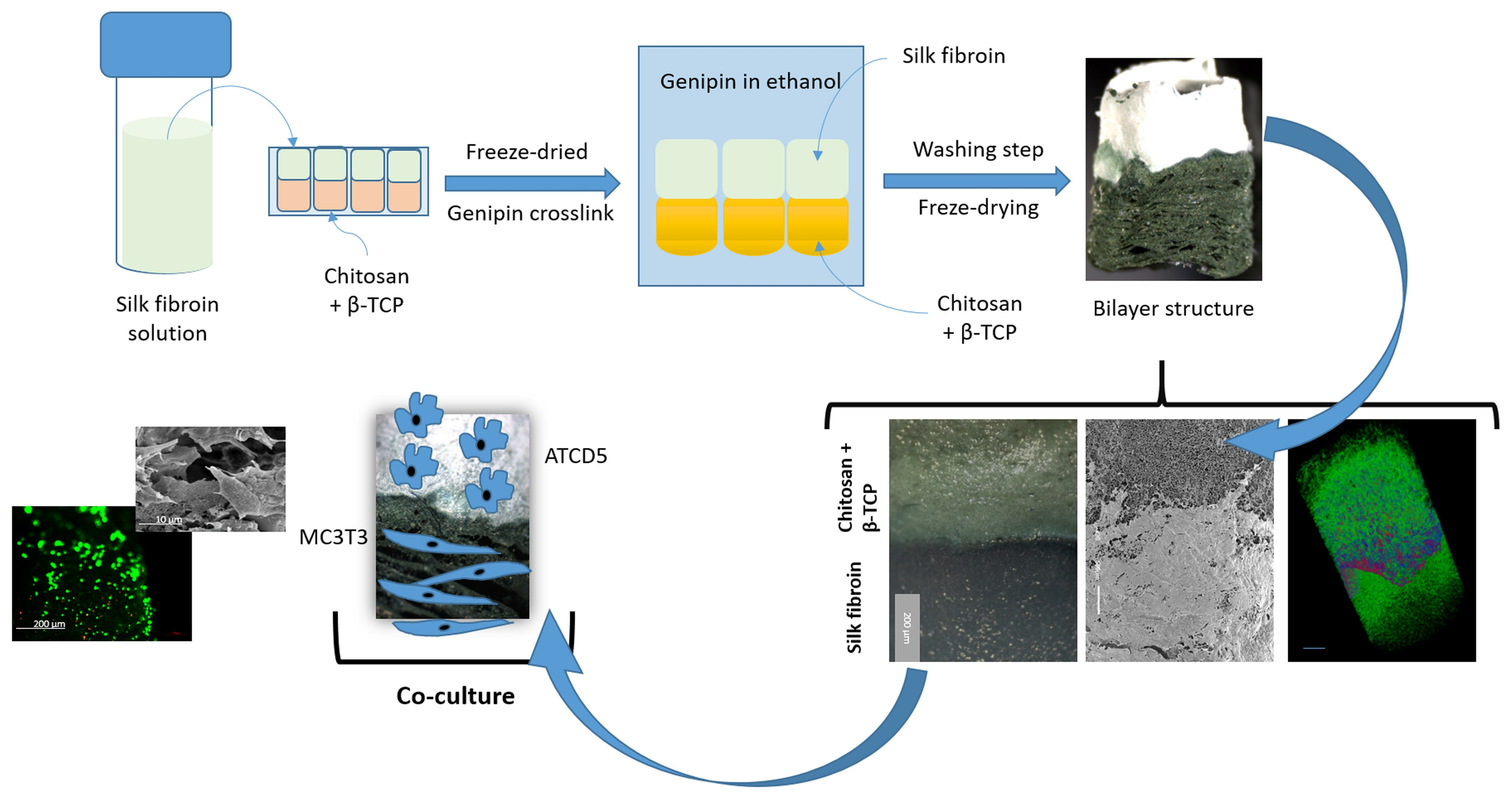
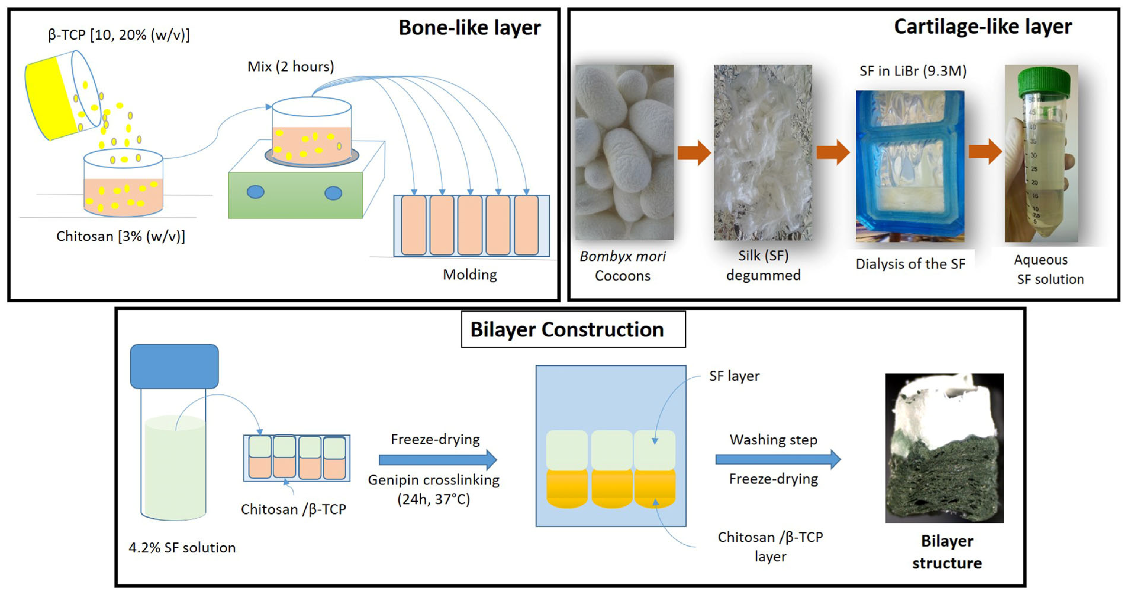
2.2. Production of the CHT/β-Tricalcium Phosphate Layer

CHT flakes were dissolved in a 0.2 M aqueous acetic acid solution at a 3 wt.% concentration to obtain a homogeneous solution. Then, the solution was filtered to remove impurities. Further, 10 and 20% (w/v) of β-TCP were added to the CHT solutions, and the systems were kept under stirring for 2 h. After that, the mixtures were molded and frozen at −80 °C overnight.

2.3. Production of Silk Layer

Silk protein fibroin was isolated from the cocoons of Bombyx mori following a standard extraction protocol [31]. Briefly, 5 g of cocoons were cut into small pieces and boiled in water containing 4.24 g de Na2CO3 for 1 h. The resulting fibroin filaments were extensively rinsed in boiling distilled water and air-dried at room temperature. Further, silk fibroin (SF) fibers were dissolved in 9.3 M LiBr, for 4 h at 70 °C. The SF was dialyzed in a Slide A-Lyzer cassette (Pierce, 3500 Da MWCO) against distilled water for 4 days at RT. The water was changed every 2 h. The resulting SF solution was centrifuged for 20 min at 5000 rpm, 7 °C, and stored at 4 °C. The concentration of the SF aqueous solution was determined by weighing the remaining solid after 1 mL of the SF solution had been dried.

2.4. Construction of Bilayered Structure

Bilayer scaffolds were fabricated by combining CHT/β-TCP and SF solutions prepared as described in Table 1. The CHT/β-TCP solution was homogenized using a magnetic stirrer for 2 h before being placed in silica molds measuring 2.5 × 10 mm. The molded samples were then kept at −80 °C overnight and freeze-dried at −79.5 °C and 0.08 mbar (using Telstar’s LyoQuest Plus Eco model) for three days. The SF solution was added to the previously freeze-dried structures, and they were frozen at −80 °C to form the SF layer (to mimic the cartilage layer). These frozen samples were then immersed in a solution of 20 mM genipin for 24 h at 37 °C for crosslinking reaction. Subsequently, the samples were washed and freeze-dried, and the bilayer architecture was constructed. CSG samples had one layer of CHT and the other of SF, which were also used as control materials. CBSG10 and CBSG20 had one layer of CHT with 10% and 20% β-TCP, respectively, and an additional layer of SF. These samples were prepared following the same procedure described above (as shown in Scheme 1).

2.5. Determination of Crosslinking Degree

The crosslinking degree of the scaffolds was evaluated using the trypan blue method, as previously reported [21,32]. The trypan blue method quantifies the differences in the concentration of free amines between noncrosslinked and crosslinked material [32]. Briefly, a standard curve was constructed using purified CHT with an acetylation degree of 10%, and different concentrations of trypan blue solutions (from 0.1 to 1% v/v). Then, the crosslinked and noncrosslinked samples were immersed in a known concentration of trypan solution (1% v/v) overnight. After that, the supernatant was collected, and the absorbance was measured at 630 nm using a microplate reader (Synergy HT; Bio-Tek, Santa Clara, CA, USA). The crosslinking degree was calculated using Equation (1)
C L % = N H 3 + n o n   l i n k e d   s o l u t i o n N H 3 + l i n k e d   s o l u t i o n N H 3 + n o n - l i n k e d   s o l u t i o n
where NH3+ nonlinked (noncrosslinked) and NH3+ linked (crosslinked) solutions are the free charge amines in noncrosslinked and crosslinked tubes, respectively.

3. Characterization of the Scaffolds

3.1. Scanning Electron Microscopy (SEM)

The samples’ morphology was evaluated by SEM using a Hitachi TM3030 countertop model, operated at 15 kV. All samples were fixed to the aluminum stubs by double-sided carbon conductive adhesive tape and gold-sputtered using a sputter coater (E6700; Quorum Technologies, East Grinstead, UK).

3.2. Micro-Computed Tomography

The scaffolds’ microstructure was evaluated using micro-computed tomography (μ-CT) SkyScan 1272 scanner (v1.1.3, Bruker, Boston, MA, USA). The X-ray source was set at 71 keV, and 140 μA and 300 projections were acquired over a rotation range of 360°. The same representative volume of interest (VOI) was analyzed for all samples. These data sets were used for morphometric analysis (CT Analyzer, v1.17.0.0, Skyscan, Belgium) and to build the three-dimensional (3D) models (CT vox, v3.3.0 r1412, Skyscan, Belgium). At least two samples per formulation were analyzed.

3.3. Optical Microscopy

Samples were analyzed at 10× and 40× magnification. The samples were analyzed in a hydrated state. The stereo microscope lamp (Schott KL 200, model Stemi 1000, Oberkochen, Germany, ZEISS) was used to photograph the scaffolds in situ.

3.4. Mechanical Tests

The mechanical properties of the developed scaffolds were carried out on cylindrical specimens with dimensions of 10 mm diameter × 2.5 mm height under compression mode using an Instron 4505 universal mechanical testing equipment. The tests were performed at room temperature using a load cell of 50 N and a crosshead speed of 1 mm/min. The elastic modulus was calculated as the stress ratio to strain or the slope of the initial linear region of stress versus strain plot, using the initial cross-sectional area in the calculations. At least five specimens were tested per condition.

3.5. Fourier-Transform Infrared Spectroscopy

The infrared spectra of the structures were obtained with a Shimadzu-IR Prestige 21 spectrometer in the spectral region of 400–4000 cm−1, with a resolution 4 cm−1 for a number of 32 scans. The samples used for the FTIR analysis were freeze-dried and powdered, mixed with KBr, and processed into pellets. The quantification of the secondary structure was based on the analysis of the amide I and amide II regions (1700–1450 cm−1) [33,34]. Collected spectra were linear baseline corrected, normalized, and deconvoluted by fitting with a Lorentzian function using PeakFit software 11.0 (Systat Software Inc., CA, USA). The average percentage for the secondary structures, mainly β–sheet, random-coil/α-helix, and β–turns, were calculated by integrating the area of each deconvoluted peak curve, normalizing the obtained value to the total area of the amide I and amide II regions [34].

3.6. Bioactivity Assay

The bioactivity of the scaffolds was evaluated by immersing them in a simulated body fluid solution (SBF), at 37 °C, prepared according to Kokubo [35], for up to 7 days. The concentrations of phosphorus and calcium in the SBF solution were determined by inductively coupled plasma optical emission spectroscopy (ICP-OES) (JY2000-2, Jobin Yvon, Horiba). The solutions were filtered with a 0.22 μm filter and diluted (1:10) in 5% nitric acid (HNO3). A minimum of three samples was used per condition and time point.

3.7. Swelling Test

Dry-weighted samples were immersed in different pH solutions (5.7 and 7.4) at 37 °C during predetermined time points to determine the swelling degree. The swelling ratio was measured by comparing the change in the weight of samples before and after immersion. The following formula calculated the percentage of swelling ratio:
S w e l l i n g   r a t i o % = W w W i × 100 %
where Ww is the weight of the swollen samples and Wi is the initial weight of the samples.

3.8. In Vitro Enzymatic Degradation

The samples’ enzymatic degradation was evaluated for 7 days using a lysozyme solution (13.0 mg/L) in PBS. Bilayered scaffolds (2.5 × 10 mm) were immersed in the lysozyme solution. All systems were kept at 37 °C, and the enzyme solution was replaced every 48 h with the freshly prepared solution to maintain the enzyme activity. Samples were collected at different time points, washed gently with distilled water, dried at 37 °C, and weighed. Percentage weight loss at respective time points was calculated as follows:
W e i g h t   l o s s   r a t i o = m i m d m i × 100 %
where mi is the initial dry weight of the sample, and md is the dry weight of the degraded sample at each time point. Three samples per group were used for each time point.

3.9. Cell Assays

3.9.1. Cell Seeding

Before the cell culture experiments, the scaffolds were sterilized in an ethylene oxide atmosphere. The MC3T3 preosteoblast cell line (ATCC CRL-2593) and the ATDC5 chondrocyte-like cells (mouse 129 teratocarcinoma AT805 derived, ECACC, Salisbury, UK) were used for direct contact assays. The cells were expanded in Minimum Essential Medium (α-MEM) (Sigma) supplemented with 10% (v/v) fetal bovine serum (FBS, Sigma, Darmstadt, Germany) and 1% penicillin-streptomycin (Gibco, MA, USA) for the MC3T3 cell line, and Dulbecco’s Modified Eagle Medium- Low glucose (DMEM) (Sigma) supplemented with 10% (v/v) FBS, Sigma 1% penicillin-streptomycin, for the ATDC5 cell line. During the experiments, the cells were maintained at 37 °C in a humified CO2 (5%) atmosphere.
The MC3T3 and ATDC5 cells (cell passage P32 and P15, respectively) were seeded onto scaffolds (2.5 × 10 mm) at a density of 100,000 cells/cm3. The cells were kept in a duo culture system. The MC3T3 cells were seeded in the CHT/β-TCP scaffolds layer, and the ATDC5 cells were seeded after 24 h in the SF layer (Scheme 2). A culture medium of 1:1 of α-MEM supplemented with 10% (v/v) FBS, 1% penicillin-streptomycin, and DMEM supplemented with 10% (v/v) FBS 1% penicillin-streptomycin was used in the duo cultures. The cells were maintained at 37 °C in a humidified CO2 (5%) atmosphere. The culture medium was replaced twice per week. At the end of each culture time point, the samples were collected, rinsed with PBS, and evaluated in terms of cellular behavior by live–dead, cytotoxicity, MTS ([3-(4,5-dimethylthiazol-2-yl)-5-(3-carbozymethoxyphenyl)-2-(4-sulfophenyl)-2H-tetrazolium]) test, DNA quantification, alkaline phosphatase (ALP) activity, and cell morphology. All experiments were made in triplicate.

3.9.2. Cytotoxicity

To assess the eventual cytotoxicity of the developed matrices, extracts were prepared as previously described by Gomes et al. [36], and placed in contact with the MC3T3 cells (cell passage P32) following the protocols described in ISO/EN 10,993 [37]. The cells were kept at 37 °C in a humidified 5% CO2 atmosphere and further seeded at a concentration of 10,000 cells/cm3 in 96-well plates. After 24 h of culture, the media containing the scaffold extracts was added to the cells. Also, a positive control (+) that is related to the number of live cells, the MC3T3 cell line, was used at the bottom of the plate.

3.9.3. Cell Viability

Cell viability was quantified using the MTS assay and the CellTiter 96® AQueous One Solution Cell Proliferation Assay Kit (Promega, Fitchburg, WI, USA). The assay was performed by leaving the MTS media (5:1 of medium and MTS assay) in contact with the samples for 3 h. After, the supernatant was collected, and a volume of 100 µL was transferred into a 96-well cell culture plate. Colorimetric measurement of the samples was performed on a microplate reader (Synergy HT; Bio-Tek, VT, USA) at 490 nm. Also, MC3T3 and ATDC5 were used as the control cells of the lines at the bottom of the plate.

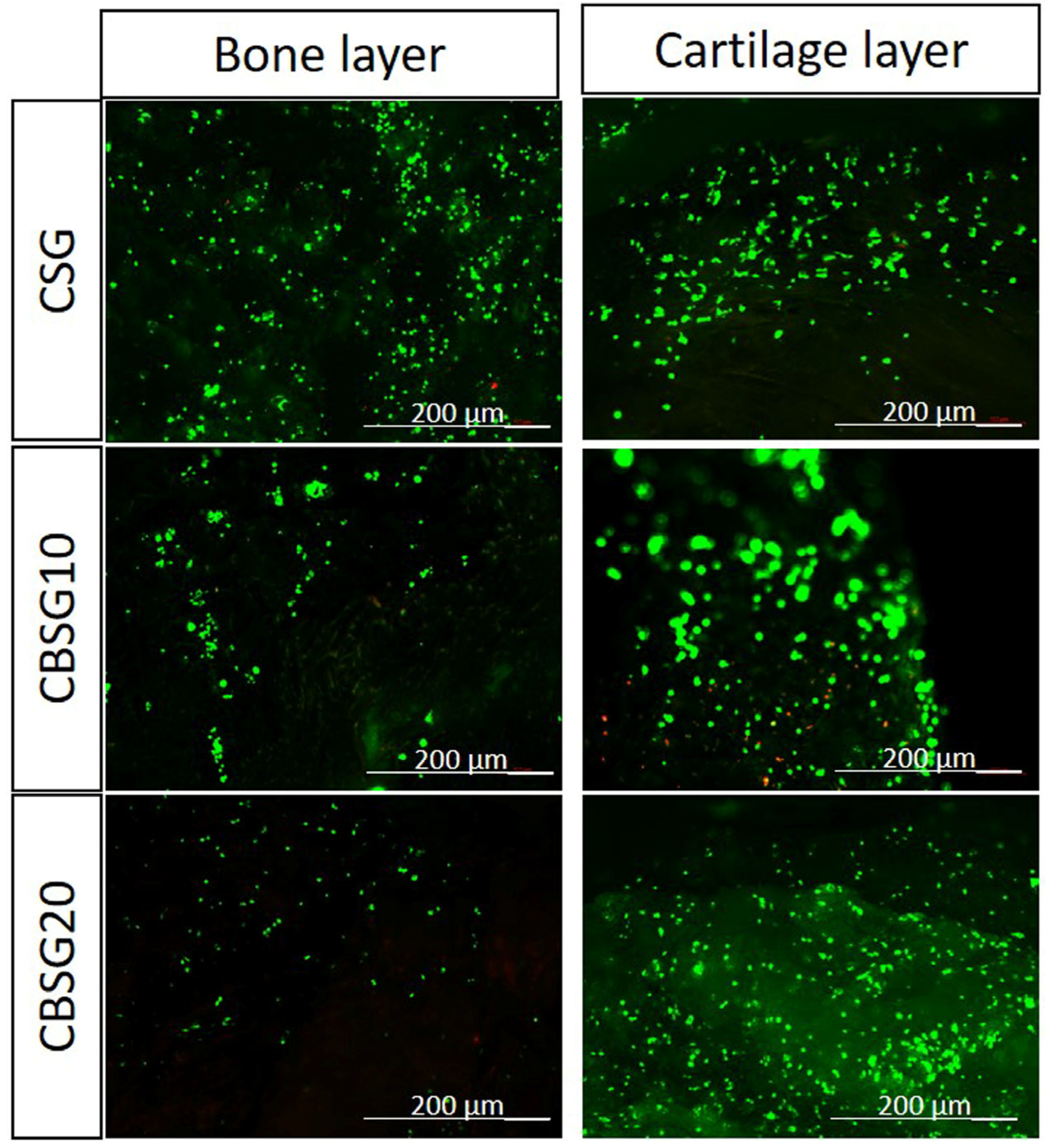
3.9.4. Live–Dead Assay

Calcein acetoxymethyl ester (Calcein AM) was used to stain live cells, and Propidium Iodide (PI) (Molecular Probes®; Life Technologies, Carlsbad, CA, USA) was used to stain dead cells on scaffolds after cell culture. Calcein AM/PI (1:2) stain was added to 1 mL of DMEM, and each sample was immersed in 100 µL/mL of this solution for 20 min at 37 °C under a 5% CO2 atmosphere. The samples were observed in a transmitted and reflected light microscope with apotome 2 (Axio Imager Z1 m; Zeiss, Jena, Germany), showing viable cells as green and nonviable cells as red. The laser was set at 488 nm and 543 nm for Calcein AM and PI, respectively. The obtained images were analyzed using the software Zen (Zen 3.2 blue edition) and a Z-stack function.

3.9.5. Cell Proliferation

The cell proliferation was quantified using a Quant-iTTM PicoGreen assay kit (Molecular Probes), according to the manufacturer’s instructions. Briefly, after 1, 3, 7, and 14 days of culture, the medium was aspirated, and the scaffolds were washed with 500 µL of PBS. Subsequently, 1000 µL of ultra-pure water was added to each sample, followed by freezing at −80 °C until analyzed. For the analysis, the samples were sonicated for 30 min each. Then, 100 µL of the supernatant was added to a 96-well flat-bottom plate. Next, PicoGreen reagent (100 µL) was added to the wells containing either the standard or sample, and the fluorescence of the samples was measured with a microplate reader (Synergy HT; Bio-Tek, Santa Clara, CA, USA), at excitation/emission wavelengths of 485/538 nm. The DNA concentration was calculated using a standard curve (range 0–2 µg/mL) relating the amount of dsDNA to the fluorescence intensity.

3.9.6. ALP Activity

The samples used for the DNA quantification assay were used to determine the ALP activity. The ALP assay mixture containing 0.1 M 2-amino-2-methyl-1-propanol (Sigma), 1 mM MgCl2, and 8 mM p-nitrophenyl phosphate disodium was added to the samples. Following 10 min of incubation at 37 °C, the reaction was stopped with 0.1 N NaOH. The resulting solution’s absorbance was measured photometrically at 405 nm using a microplate reader (Synergy HT; Bio-Tek, Santa Clara, CA, USA).

3.9.7. Cell Morphology

Following the cell culture, the samples were fixed by immersion in 2.5% (v/v) formalin solution for 1 h at 4 °C. The fixed constructs were further dehydrated by immersion in a series of aqueous ethanol solutions, gradually increasing ethanol concentration from 20% to 100% v/v. The constructs were sputter-coated with gold and observed under SEM.

3.10. Statistical Analysis

Standard deviations are expressed in a representative of three similar experiments carried out in triplicate. Statistical analysis was performed with data from cell culture, using a one-way analysis of variance (ANOVA) by the Bonferroni test. A p-value < 0.05 was considered statistically significant by the Graph-Pad Instant (GraphPad Software, San Diego, CA, USA) statistics program. Moreover, the statistical analysis was performed for the mechanical tests by applying a Shapiro–Wilk normality test to confirm if the samples followed a normal distribution. When the assumption was violated, nonparametric tests were used for multiple comparisons (Kruskall–Wallis test). Statistical significance was accepted at p < 0.05.

4. Results and Discussion

Typically, for osteochondral regeneration, a 3D porous structure is prepared by the freeze-drying and salt-leaching techniques [3,7]. Our strategy involved the development of 3D architectures composed of two distinct layers, namely CHT/β-TCP and SF. CHT from marine origin was chosen due to its intrinsic properties, such as nontoxicity, biodegradability, easy handling, and the possibility to interact with different molecules and materials [12,14,16,17], while β-TCP would enhance the osteoconductive features and bioactivity of the structures. Ultimately, SF, a natural protein [14,19,21], would act as an additional layer to enhance physicochemical and biological features in the bilayered structure. Moreover, to build up the CHT/β-TCP/SF bilayered structure, it was necessary to study the ratio used by each component to produce the developed scaffolds, which was optimized in preliminary tests. Finally, the combination of CHT (3% w/v), β-TCP (10 and 20%), and SF (4% w/v) was used, followed by genipin crosslinking to enhance the bonding between the layers. Table 1 shows the identification and composition of the formulations produced, being CSG—chitosan 3% (w/v) and silk fibroin 4.2% (w/v); CBSG10—chitosan 3% (w/v), β-TCP 10% (w/v), and silk fibroin 4.2% (w/v); and CBSG20—chitosan 3% (w/v), β-TCP 20% (w/v), and silk fibroin 4.2% (w/v), respectively.
From optical microscopy analysis of the CSG, CBSG10, and CBSG20 matrices (Figure 1), it was possible to identify the layers, namely SF (light gray) and CHT/β-TCP (blue/green) (Figure 1a). Additionally, the SEM micrographs (Figure 1b,c) confirmed the presence of different layers in the architectures. Moreover, the effect of genipin crosslinking on the structures was evidenced by a dark blue-green coloration on the CSG sample and a light blue-green on the CBSG10 and CBSG20 samples (Figure 1a). Similar behavior was observed in other studies [14,38,39,40], whereas the coloration was related to the oxygen radical-induced polymerization of genipin and its reaction with amino groups/amino acids. Genipin crosslinking reacts preferentially with amine groups present in CHT, creating chemical crosslinkages in the CHT, but it can also react with some SF amino acids [21,40,41]. Therefore, we hypothesized that the genipin reaction took place initially in the CHT/β-TCP layer and, to a lesser extent, in the extended SF layer, promoting a rearrangement of the whole structure that could affect the β-sheet formation in SF. Further, the crosslinking degree of the scaffolds was determined, and the values found were 10%, 24%, and 21% for the CSG, CBSG10, and CBSG20 scaffolds, respectively.

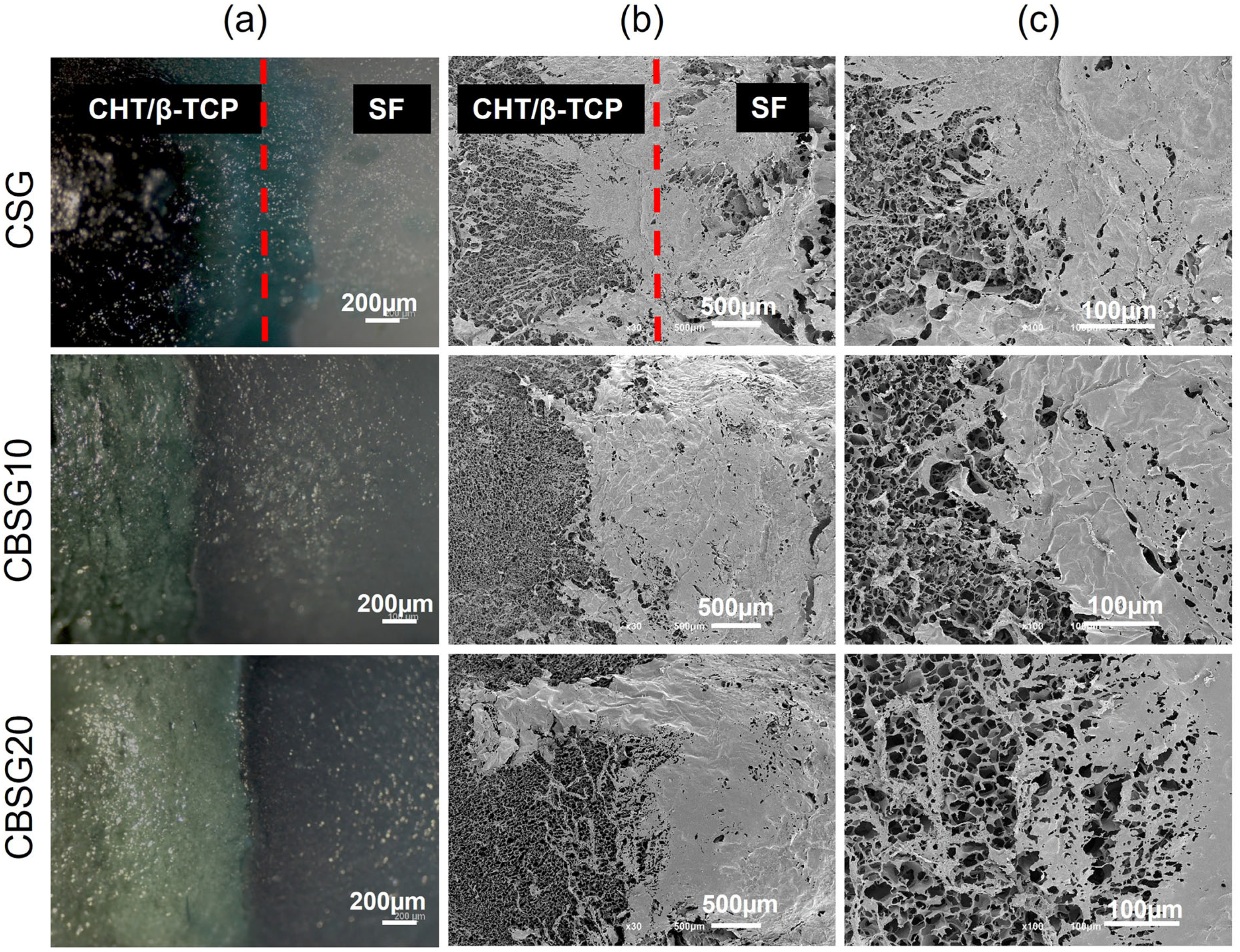
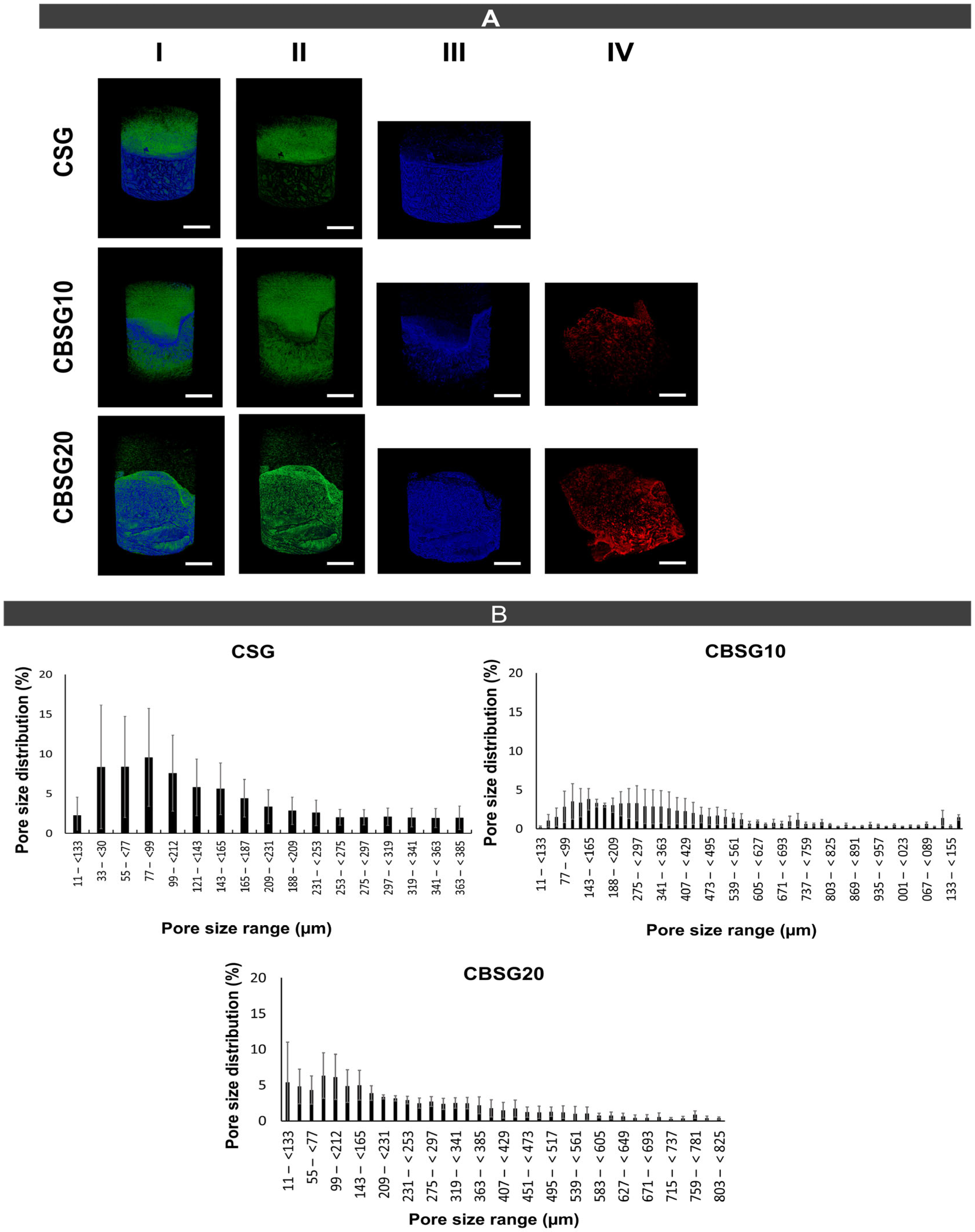
4.1. Morphological Features

The distribution of the different components throughout the bilayered scaffolds and the quantitative analysis of their 3D morphometric parameters (thickness, pore size distribution, and porosity) were assessed by micro-CT (Figure 2 and Table 2). In Figure 2A, we can observe the composition of the scaffolds on the different layers, namely CHT (bottom-blue), β-TCP (red), and SF (top-green). The micro-CT analysis evidenced that the CSG scaffolds presented a well-designed interface structure, and the layers SF and CHT were also well defined (Figure 2A). In the scaffolds with β-TCP, CBSG10, and CBSG20, the SF layer seems to be spread along with the CHT layer (Figure 2A), whereas β-TCP was only found in the CHT layer as expected (Figure 2A). Unfortunately, the dimensions of the structures used in this study, including in the mechanical tests, are less than 10 mm, making it not possible to fix the structure in the machine grips and perform the test to determine the binding strength. Figure 2 shows that SF could impregnate the CHT layer in the presence of β-TCP.
Moreover, the CSG scaffolds made with CHT and SF have a microstructure with similar values between the two layers, namely 73.71 ± 11.22 µm in the top layer, 65.22 ± 5.44 µm in the interface, and 77.37 ± 1.15 µm in the bottom layer (Table 2). Also, the thickness and porosity of the CSG scaffolds showed similar values (Table 2). However, we observed a different pattern in the scaffolds with β-TCP, namely CBSG10 and CBSG20 (Table 1). Herein, the pore size in the scaffolds’ interface and CHT layer diminished compared to the CSG scaffolds. This is possibly due to the SF infiltration on the CHT/β-TCP layer (Figure 2A). Likewise, the scaffold thickness and porosity were lower in the interface and CHT layer (Figure 2A). The morphological features, mainly porosity and pore size, in both bilayered scaffolds, CBSG10 and CBSG20, showed significant differences. In the CBSG10 scaffolds, the porosity of the SF layer was 71.21 ± 9.77%, whereas in the CBSG20 scaffolds, the porosity was 54.42 ± 0.68%, respectively. These findings indicated a decrease in porosity at the interface on these scaffolds. The porosity of the CBSG10 and CBSG20 scaffolds was 31.55 ± 0.64% and 31.20 ± 1.06%. In the bottom CHT/β-TCP layer, the porosity of the CBSG10 and CBSG20 scaffolds was also reduced compared to the CSG scaffolds (Table 2).
The results indicate that in the top layer, there is no significant difference (p < 0.05). At the interface of the scaffolds CSG and CBSG10, CSG, and CBSG20, there are significant differences (p < 0.05) in all aspects (thickness, pore size, and porosity). In the results of the bottom layer for porosity, significant differences were found (p < 0.05) in all scaffolds, whereas for the aspects of thickness and pore size significant differences were only found between CSG and CBSG10, CSG, and CBSG20 (Table 1). Our results suggest that increasing the concentration of β-TCP on the CHT layer reduced the scaffold’s porosity, and the SF impregnation along the CHT/β-TCP could help with that effect, as confirmed by the micro-CT results (Table 2). However, the freeze-drying technique has been shown to be relevant for processing hierarchical porous structures [42,43], where the ice crystals’ formation during freeze-drying could also influence the materials’ porosity.

4.2. Mechanical Properties

The mechanical properties of the CHT/β-TCP bilayered scaffolds were assessed by uniaxial compression tests, and the results are provided in Table 3 and the stress–strain curves are available in the Supplementary Information, Figure S1. The elastic modulus obtained under the compression load for the scaffold CSG was 3.0 ± 1.5 MPa, whereas, in the CBSG10 and CBSG20 scaffolds, the elastic modulus was 3.3 ± 1.5 MPa and 1.1 ± 0.7 MPa, respectively. It was also determined that the compressive yield strength indicates the maximum stress that can be developed in the scaffold material without causing plastic deformation. The values are in the range of KPa, being the highest values of 160.5 ± 51.5 KPa, obtained for the CBSG10 bilayered scaffold. No significant statistical differences (p > 0.05) were observed between the three scaffolds due to the samples’ high standard deviation. Considering the mean values and higher concentration of β-TCP in the scaffold, a decrease in stiffness was observed. This decrease for higher concentrations of β-TCP might be attributed to the differences in the affinity between the constituents, which supports the observed decrease in stiffness in the mechanical properties. This finding agrees with the previously discussed results for the crosslinking degree and micro-CT analysis, showing that CBSG10 can be the most promising bilayered scaffold among our formulations targeting osteochondral strategy. According to the literature [44], CHT-based scaffolds had weak mechanical properties, restricting their application in bone TE. Therefore, adding bioactive ceramics or other polymers to CHT has been used to overcome those drawbacks. In our strategy, β-TCP was incorporated into CHT in different concentrations, which, together with the SF layer, allowed the building of bilayered scaffolds with modulated mechanical properties. The mechanical properties also suggest that the scaffolds may have acceptable mechanical properties for in vivo applications as a bone void filler. We highlight that the compressive properties of the scaffolds are slightly lower than that of cancellous bone. However, the literature indicates that it is unknown what minimum strength is required for in vivo success of the scaffold, because the surrounding bone may provide protective support, and as the scaffold continues to deteriorate, the new bone will enter it and repair it [45]. It is also relevant to keep in mind that the obtained values are for dry samples and that the aqueous environment will have some effect on the mechanical properties during the implantation.

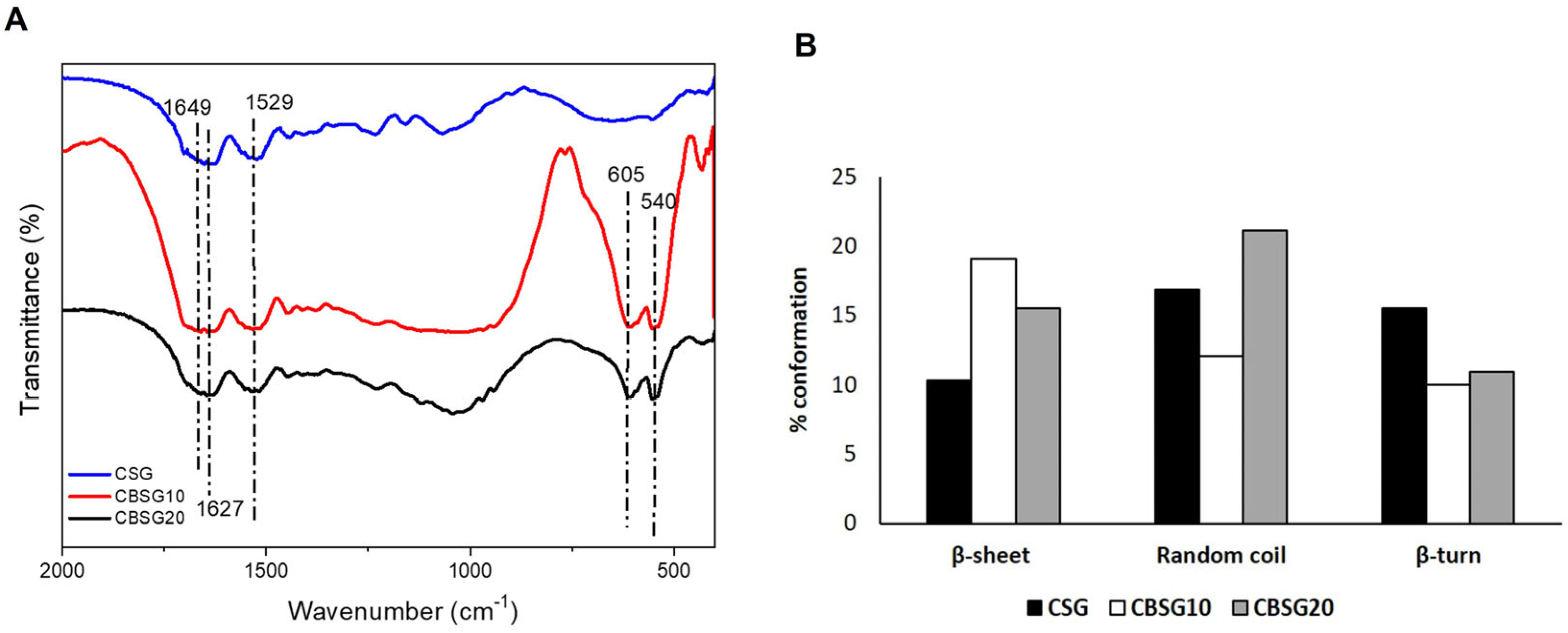
4.3. Structural Features

We assessed the conformation changes of the developed scaffolds by FTIR (Figure 3). We observed SF, CHT, and β-TCP characteristics in all scaffolds in the FTIR spectra. The scaffolds CSG, CBSG10, and CBSG20 exhibited a strong N-H peak (3260 cm−1), characteristic of CHT N-H stretching vibration (Figure 3A). In addition, there are vibrational modes in the range of 1650–1647 cm−1 corresponding to the amide I region, indicating α-helix/random coil conformations, and peaks also appeared in the 1620–1630 cm−1 range, as well as in the amide II region with a range of 1510–1530 cm−1, indicative of antiparallel β-sheet structures [46]. Furthermore, the scaffolds CBSG10 and CBSG20 exhibit peaks with a strong vibrational mode in the 540–605 cm−1 range, indicative of the presence of PO4−2 groups [47], while in the CSG scaffolds, we cannot observe these peaks (Figure 3A).
The spectral deconvolution of amide I and II was assessed to determine alterations to the β-sheet conformation on SF (Figure 3B). The β-sheet content in the scaffolds was 10.3% for CSG, 19.1% for CBSG10, and 15.5% for CBSG20 scaffolds, whereas the α-helix/random coil conformations was 16.7% for CSG, 12.1% for CBSG10, and 21.1% CBSG20 scaffolds (Figure 3B). Results show that the increasing β-TCP concentration significantly diminishes the formation of the β-sheet on the CBSG20 scaffold compared to the CBSG10 scaffold (Figure 3B), inferring that β-TCP greatly influenced SF β-sheet conformation [48]. The higher percentage of β-sheet conformations associated with a higher crosslinking degree (24%) in the CBSG10 scaffolds suggests that this scaffold can have better structural stability and water insolubility. In addition, it demonstrates that the SF’s core self-assembling maintained the formation of β-sheet crystals in the scaffolds. Therefore, the chemical characterization evidenced the good interaction between the components of the different layers, SF, CHT, and β-TCP, mainly in the CBSG10.

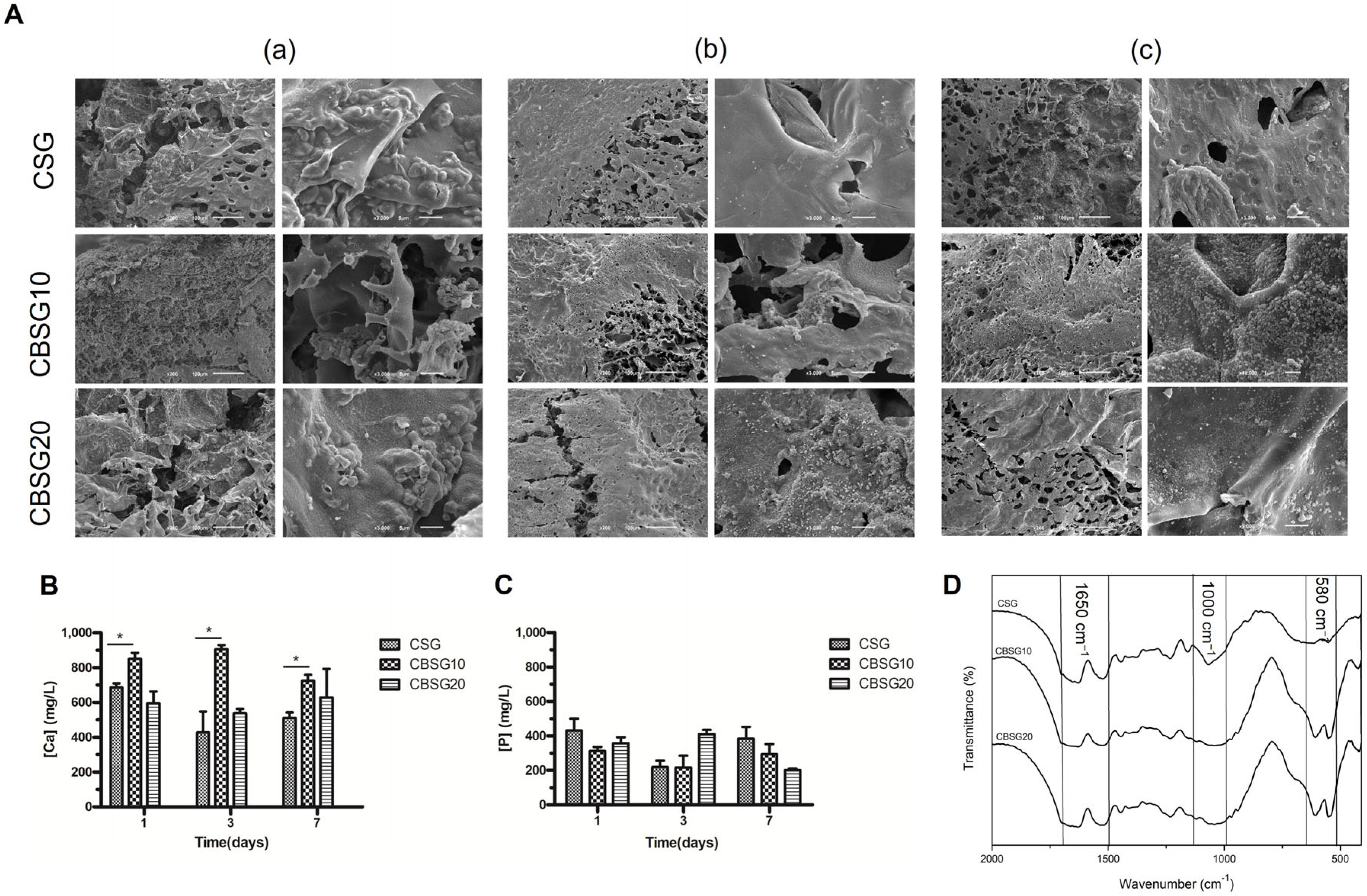
4.4. Bioactivity Behavior

The present study aims to engineer a bilayered scaffold, enabling an interface that binds cartilage to the bone through the osteochondral interface. By doping the bilayer scaffold with β-TCP, we attempt to induce the biomineralization of the scaffold [49,50]. The Ca/P layer formation on the surface of the scaffolds was evaluated for up to 7 days by immersing in simulated body fluid (SBF) and further characterized by SEM, ICP, and FTIR (Figure 4).
In SEM micrographs (Figure 4A), it is possible to observe the formation of a new apatite layer on the surface of all scaffolds. We further determined the concentration of Ca and P in the SBF after 1, 3, and 7 days of incubation (Figure 4B). After one day, a higher Ca concentration was found in the solutions for CBSG10 scaffolds, while the Ca content for CSG and CBSG20 scaffolds were lower. After days 3 and 7 of immersion, Ca content in the SBF solution diminished in the CBSG10 scaffolds and the other scaffolds tested, suggesting that the scaffolds have absorbed Ca. There are significant differences (p < 0.05) between the CSG and CBSG10 samples in the Ca concentration. Regarding P content in the SBF solution, P uptake from the SBF solution was lower in the CBSG10 scaffolds than in the other formulations after 1-day immersion (Figure 4C). The same trend was observed after 3 and 7 days of immersion (Figure 4C). Our results demonstrate a decrease in the ion concentrations in the SBF solutions after 7 days for all scaffolds. The data in the concentration of P do not show statistically significant differences. In this study, the decrease in Ca and P ions in the solution and SEM analysis indicated that the apatite crystals in the structure follow the same trend as observed in previous studies [4]. In addition, apatite formation on the scaffold’s surface can promote cell proliferation and differentiation, triggering osteogenic cell growth [51]. We observed no changes in the peaks of the phosphates ions, carriers of Ca and P ions, after the bioactivity test in the FTIR spectra (Figure 4D). Regarding SF, FTIR analysis of the amine I region in the range of 1650–1647 cm−1 indicates variations to the α-helix/random coil conformations of SF, suggesting that the addition of β-TCP did not affect SF. The observed peaks in the 540–605 cm−1, region indicate the presence of PO4−2 groups [52] and PO4−3, bending vibrations appear at 604 cm−1, as expected for β-TCP. The results indicate that the apatite layer in the CBSG10 and CBSG20 scaffolds resulted in a higher Ca/P ratio when compared to the control scaffolds.

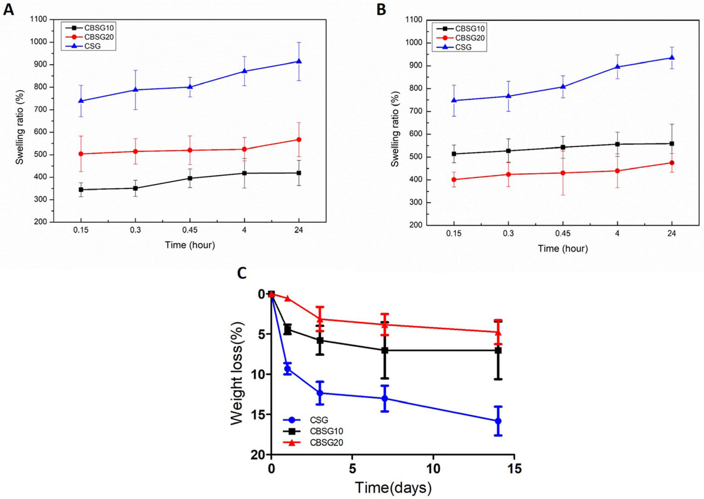
4.5. Swelling and In Vitro Enzymatic Degradation

4.5.1. Swelling

The ability of a scaffold to uptake and preserve water within its structure is an important feature when developing suitable tissue engineering constructs, especially for cartilage and osteochondral regeneration. We tested the water uptake ability of the scaffolds at pH 5.7 and neutral pH. The swelling degree of the CSG scaffolds increased in the acidic pH and showed the same trend in pH 7.4 (Figure 5A,B). The high swelling degree at low pH occurs due to the protonation of the free amino groups present in CHT [14,53]. The protonation increases the solubility of the polymeric segments and could cause polymer chain repulsion since it interacts with water molecules, allowing more water to penetrate into the scaffold architecture. In the CBSG10 scaffolds, the swelling profile slightly increases over time at pH 7.4 and 5.7 (Figure 5A,B). We hypothesized that in CBSG10, some free amino groups could still influence this behavior, while in CBSG20, the inorganic content is much higher, resulting in a lower swelling percentage.
Moreover, the swelling degree of the CBSG10 and CBSG20 for both pHs showed a strong reduction compared to noncrosslinked material (CSG scaffolds), which could be related to the inorganic phase (β-TCP). Similar behavior on the swelling was observed in systems containing β-TCP and CHT derivatives in a gelatin matrix where the increase of the ceramic phase restricted the water adsorption [50]. As reported in previous studies [14,54], crosslinking may also modulate water uptake since it can create stable matrices. The introduced crosslinks created stable structures that inhibit the swelling of the hydrophilic polymer chains. In addition, the micro-CT results demonstrated that CBSG10 and CBSG20 scaffolds have lower porosity than CSG scaffolds (Figure 2 and Table 1), which can also contribute to the lower water uptake of the scaffolds.

4.5.2. In Vitro Enzymatic Degradation

We assessed the scaffolds’ in vitro biodegradation behavior in the presence of an enzyme (lysozyme). Enzymatic degradation of medically graded polymers is used to determine which degradation products are once in vivo and if they are toxic to cells. In particular, lysozyme, an enzyme found in the human body [40,55], is applied in chitosan-based scaffolds to modulate its materials characteristics since in vivo lysozyme hydrolyzes the CHT linkages, and the final product of degradation, glucosamine, is nontoxic to cells [56]. Furthermore, to our knowledge, as for SF, there are no reported studies indicating that lysozyme affects SF. After 24 h, the scaffolds started to degrade with weight loss values of 9% (CSG scaffolds), 4% (CSBG10 scaffolds), and 0.6% (CSBG20 scaffolds) (Figure 5C). However, the weight loss reached values up to 16% (CSG scaffolds), 7% (CBSG10 scaffolds), and 5% (CBSG20 scaffolds) (Figure 5C) after 15 days. These results may occur due to the enhancement of the structure’s stability promoted by genipin crosslinking, as evidenced in other studies [40,57]. Qasim et al. suggested that the stability of genipin crosslinked CHT composite scaffolds could be enhanced by the density of the scaffold into a tighter structure that prevented degradation by lysozyme [40]. Beyond that, the β-TCP could act as a protective agent in the structure, as observed in other studies [58], which collaborates with the slower degradation rate. The literature states that an osteochondral scaffold must degrade at a rate equivalent to tissue repair [59]. Therefore, the developed scaffolds’ slow rate of degradation could contribute to fulfilling the requirements for osteochondral regeneration strategies.

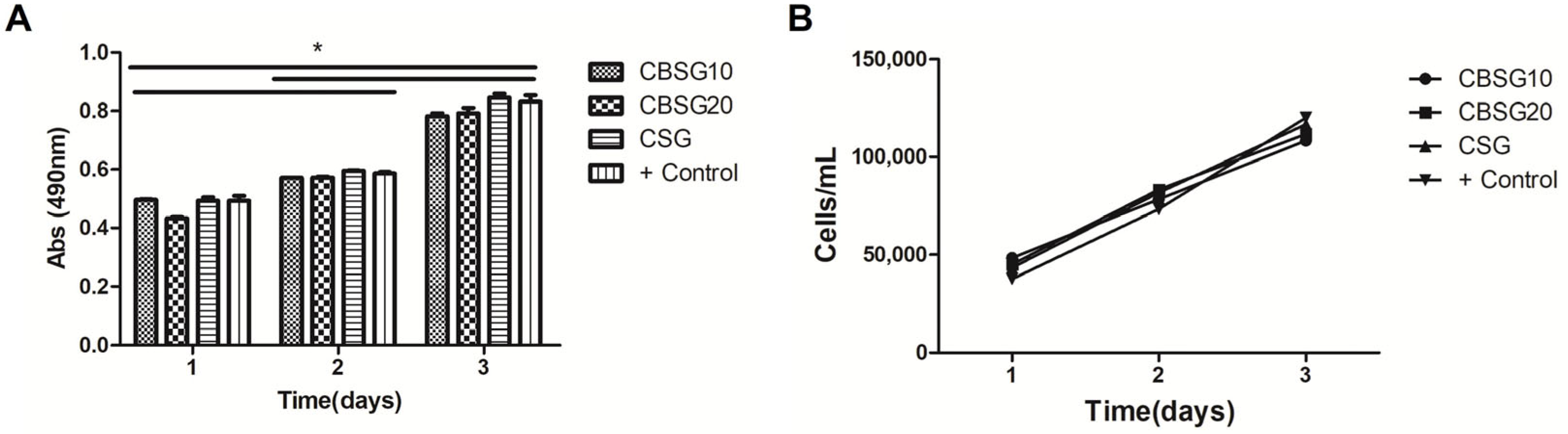
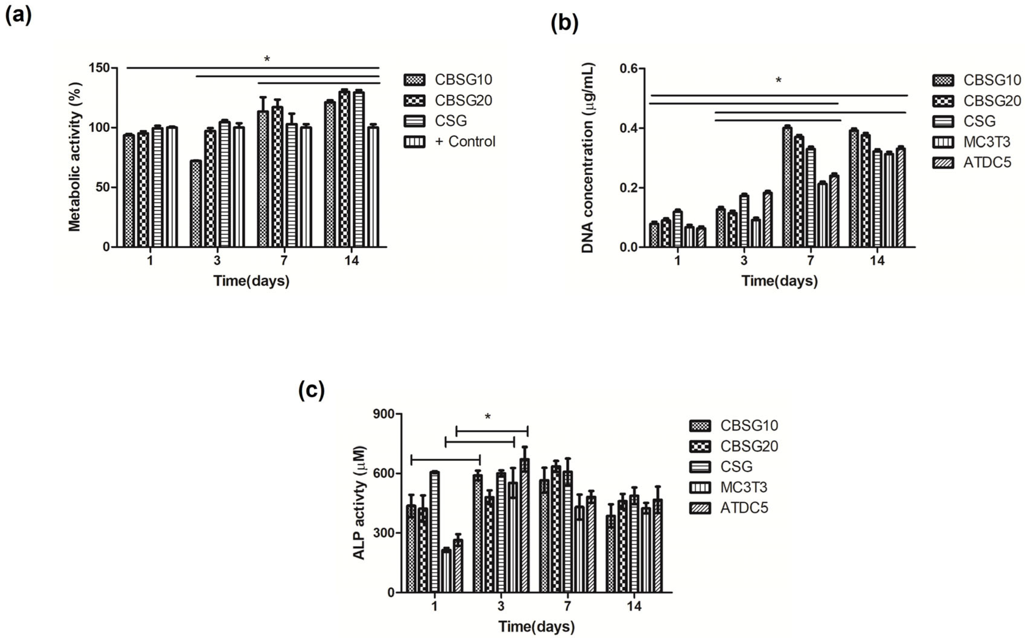
4.6. Biological Behavior

The cytotoxicity tests performed on scaffolds showed that the structures tested in the presence of MC3T3 osteoblast-like cells do not exhibit toxicity and show that the population of these cells increases over the test period (Figure 6). Also, the data do not show statistically significant differences. This outcome was anticipated due to the intrinsic features of the natural biomacromolecules (CHT, SF) and inorganic components (β-TCP) used to create the bilayered scaffolds. In addition, they have been known for their low toxicity and biocompatibility [4,19,28]. Furthermore, our primary focus was to access the potential of the developed architectures for osteochondral regeneration; therefore, as a proof of concept, we evaluated the biological performance of the scaffolds using MC3T3 osteoblast-like cells and ATDC5 chondrocyte-like cells in duo-culture conditions, and respective characterization. For that purpose, we seeded MC3T3 cells on the CHT/β-TCP layer, and 24 h after, ATDC5 chondrocyte cells were seeded in the SF layer. The cell viability and proliferation on the scaffolds showed significant statistical differences (p < 0.05) when compared to the cell cultures in tissue culture plastic (TCP) (Figure 7a,b). The cells were able to adhere and proliferate in the CSGB10 scaffolds compared to the cellular proliferation in CSG scaffolds (Figure 7b). The CBSG20 scaffolds exhibit a similar pattern (Figure 7). Moreover, cell proliferation shows significant differences after 7 and 14 days. These outcomes could be attributed to the cells’ ability to adapt to the shape and the subsequent stimulation of DNA proliferation.
The increase in cell proliferation is positively influenced by the presence of calcium phosphate, which, as previously seen, promoted osteoblasts proliferation [60]. Also, ceramic particles are expected to increase the surface’s roughness and area, leading to the proliferation and adhesion of these cells [60]. Moreover, it is anticipated that the biological performance of the matrices would improve since SF has ability to enhance attachment, proliferation, and differentiation of chondrocytes, among other types of cells [14,28,61]. These results support our hypothesis that the developed bilayered scaffolds’ structural, mechanical, and biological features provide an adequate niche to support ATDC5 and MC3T3 cell adherence and proliferation. Our results also align with previously reported studies with similar materials, such as SF, CHT, and hyaluronic acid, further supporting our findings [14,62]. Cell proliferation and calcium salt deposition could determine how fast bone and osteochondral tissue regenerate. This will establish the functionality of the tissue with the scaffold [63]. Alkaline phosphatase plays an important role in forming bone and is also used as a marker of the formation of these two tissues [64]. ALP is quantified up to 600 µM along the 14 days of culture with ATDC5 and MC3T3 cells. ALP data showed significant differences between 1 and 3 days of culture on the CBSG10 scaffolds and the controls (MC3T3 and ATDC5 cells) (Figure 7c). In the control conditions, the significant increase in ALP activity may be due to the presence of β-TCP. Moreover, we also evaluated cellular viability in each scaffold layer (Figure 8). We observed a higher number of live cells (green) compared to dead cells (red) throughout the layers of the scaffold. Also, the number of cells is higher in CSG scaffolds in the bone layer, whereas in the cartilage layer, it is higher in CBSG20, which agrees with DNA quantification (Figure 7b).
Although the expression of specific markers of osteogenic and osteochondral differentiation was not explored in the present study, the osteogenic potential of CHT and SF materials has been reported before. Previous studies have already reported on the potential of CHT, β-TCP, and SF for bone and cartilage regeneration [4,65,66]. For example, CHT is a natural, biocompatible, and biodegradable material that when combined with b-TCP can be used in bone tissue engineering [4]. Likewise, Amann et al. [66] also reported on the osteogenic differentiation and potential of CHT/collagen and calcium phosphate. Also, SF’s potential for Tissue Engineering approaches has been reported in previous studies. For instance, Pina et al. [65] successfully demonstrated the potential of bilayered scaffolds made with SF to stimulate chondrogenic and osteogenic cells in differentiation. Nevertheless, we are currently looking at more detailed studies to assess both osteogenic and chondrogenic gene expression of these new composite scaffolds and also their potential in Tissue Engineering applications.

5. Conclusions

In this study, we developed genipin crosslinked CHT/β-TCP/SF bilayered scaffolds, envisioning their use for tissue engineering strategies. Our findings revealed that the genipin crosslinking promoted a structural rearrangement in the scaffolds, improving the stability of the structures. One of the important features of the bilayered structures was the adequate integration between the two layers and the ability to maintain the porous structure. Furthermore, the morphological analysis suggested an infiltration of the SF layer throughout the CHT/β-TCP layer, which affected the porosity between interfaces of the structures. Moreover, the architectures showed slower degradation over 15 days in the presence of lysozyme, which could be helpful during the regeneration process. The obtained biological outcomes support that the developed CHT marine-based scaffolds have good ATDC5 and MC3T3 cell adherence and proliferation for 14 days. Overall, our findings indicated that among the tested scaffolds, the CSGB10 architecture sustained the flow of nutrients in the two layers, which is vital for cell proliferation culture, fulfilling the needs of each part of the tissue involved. Thus, CSGB10 can be a suitable candidate 3D matrix for osteochondral tissue engineering approaches.

Supplementary Materials

The following supporting information can be downloaded at: https://www.mdpi.com/article/10.3390/jcs8030085/s1, Figure S1: Stress-strain curves of the developed scaffolds.

Author Contributions

L.P., S.S.S. and E.M.F. developed the manuscript´s concept, experimental work, drafted the manuscript and finalized the figures. L.P., J.M.G., I.B.L. and A.R.F. performed the experimental work together with the other authors. M.C.F., G.V.S., D.H. and R.L.R. supervised the work, edited and reviewed the manuscript. All authors have read and agreed to the published version of the manuscript.

Funding

This study was partially financed by the Coordenação de Aperfeiçoamento de Pessoal de Nível Superior—Brasil (CAPES)—Finance Code 001 and Conselho Nacional de Desenvolvimento Científico e Tecnológico (CNPq), PVE 407035/2013-3. This work is also financially supported by Portuguese FCT (PD/BD/135247/2017, SFRH/BPD/93697/2013, DL 57/2016/CP1377/CT0054 (https://doi.org/10.54499/DL57/2016/CP1377/CT0054), CEECINST/00018/2021), PhD programme in Advanced Therapies for Health (PATH) (PD/00169/2013), FCT R&D&I projects with references PTDC/BII-BIO/31570/2017, PTDC/CTM-CTM//29813/2017, and PTDC/CTM-BIO/4706/2014-(POCI-01-0145-FEDER-016716). The authors would like to thank the contributions to this research from the project “TERM RES Hub—Scientific Infrastructure for Tissue Engineering and Regenerative Medicine”, reference PINFRA/22190/2016 (Norte-01-0145-FEDER-022190), funded by the Portuguese National Science Foundation (FCT) in cooperation with the Northern Portugal Regional Coordination and Development Commission (CCDR-N), for providing relevant lab facilities, state-of-the-art equipment, and highly qualified human resources.

Data Availability Statement

Data are contained within the article and Supplementary Materials.

Acknowledgments

Gratitude to Research Group, I3Bs—Research Institute on Biomaterials, Biodegradables and Biomimetics, University of Minho, for the availability granting space, equipment, and materials for the work development. The authors want to thank Eduardo H. Backes for their help with a microscope with apotome 2 (Axio Imager Z1 m; Zeiss, Jena, Germany).

Conflicts of Interest

The authors declare no conflicts of interest.

References

  1. Morouço, P.; Fernandes, C.; Lattanzi, W. Challenges and Innovations in Osteochondral Regeneration: Insights from Biology and Inputs from Bioengineering toward the Optimization of Tissue Engineering Strategies. J. Funct. Biomater. 2021, 12, 17. [Google Scholar] [CrossRef] [PubMed]
  2. Maia, F.R.; Carvalho, M.R.; Oliveira, J.M.; Reis, R.L. Tissue Engineering Strategies for Osteochondral Repair. In Osteochondral Tissue Engineering: Challenges, Current Strategies, and Technological Advances; Oliveira, J.M., Pina, S., Reis, R.L., San Roman, J., Eds.; Springer International Publishing: Cham, Switzerland, 2018; pp. 353–371. [Google Scholar]
  3. Wei, W.; Dai, H. Articular cartilage and osteochondral tissue engineering techniques: Recent advances and challenges. Bioact. Mater. 2021, 6, 4830–4855. [Google Scholar] [CrossRef] [PubMed]
  4. Piaia, L.; Silva, S.S.; Gomes, J.M.; Franco, A.R.; Fernandes, E.M.; Lobo, F.C.M.; Rodrigues, L.C.; Leonor, I.B.; Fredel, M.C.; Salmoria, G.V.; et al. Chitosan/β-TCP composites scaffolds coated with silk fibroin: A bone tissue engineering approach. Biomed. Mater. 2022, 17, 015003. [Google Scholar] [CrossRef] [PubMed]
  5. Xiao, H.; Huang, W.; Xiong, K.; Ruan, S.; Yuan, C.; Mo, G.; Tian, R.; Zhou, S.; She, R.; Ye, P.; et al. Osteochondral repair using scaffolds with gradient pore sizes constructed with silk fibroin, chitosan, and nano-hydroxyapatite. Int. J. Nanomed. 2019, 14, 2011–2027. [Google Scholar] [CrossRef] [PubMed]
  6. Pitrolino, K.A.; Felfel, R.M.; Pellizzeri, L.M.; Mlaren, J.; Popov, A.A.; Sottile, V.; Scotchford, C.A.; Scammell, B.E.; Roberts, G.A.F.; Grant, D.M. Development and in vitro assessment of a bi-layered chitosan-nano-hydroxyapatite osteochondral scaffold. Carbohydr. Polym. 2022, 282, 119126. [Google Scholar] [CrossRef] [PubMed]
  7. Shimomura, K.; Moriguchi, Y.; Murawski, C.D.; Yoshikawa, H.; Nakamura, N. Osteochondral tissue engineering with biphasic scaffold: Current strategies and techniques. Tissue Eng. Part B Rev. 2014, 20, 468–476. [Google Scholar] [CrossRef] [PubMed]
  8. Tamaddon, M.; Wang, L.; Liu, Z.; Liu, C. Osteochondral tissue repair in osteoarthritic joints: Clinical challenges and opportunities in tissue engineering. Bio-Des. Manuf. 2018, 1, 101–114. [Google Scholar] [CrossRef]
  9. Lesage, C.; Lafont, M.; Guihard, P.; Weiss, P.; Guicheux, J.; Delplace, V. Material-Assisted Strategies for Osteochondral Defect Repair. Adv. Sci. 2022, 9, e2200050. [Google Scholar] [CrossRef]
  10. Browe, D.C.; Díaz-Payno, P.J.; Freeman, F.E.; Schipani, R.; Burdis, R.; Ahern, D.P.; Nulty, J.M.; Guler, S.; Randall, L.D.; Buckley, C.T.; et al. Bilayered extracellular matrix derived scaffolds with anisotropic pore architecture guide tissue organization during osteochondral defect repair. Acta Biomater. 2022, 143, 266–281. [Google Scholar] [CrossRef]
  11. Zheng, X.; Li, N.; Xu, Y.; Zhang, C.; Ouyang, Y.; Meng, D. A bilayer collagen scaffold with bevacizumab stabilizes chondrogenesis and promotes osteochondral regeneration. Mater. Des. 2022, 221, 110981. [Google Scholar] [CrossRef]
  12. Silva, S.S.; Rodrigues, L.C.; Fernandes, E.M.; Reis, R.L. Chapter 1—Fundamentals on biopolymers and global demand. In Biopolymer Membranes and Films; de Moraes, M.A., da Silva, C.F., Vieira, R.S., Eds.; Elsevier: Amsterdam, The Netherlands, 2020; pp. 3–34. [Google Scholar]
  13. Islam, N.; Hoque, M.; Taharat, S.F. Recent advances in extraction of chitin and chitosan. World J. Microbiol. Biotechnol. 2022, 39, 28. [Google Scholar] [CrossRef]
  14. Silva, S.S.; Motta, A.; Rodrigues, M.T.; Pinheiro, A.F.; Gomes, M.E.; Mano, J.F.; Reis, R.L.; Migliaresi, C. Novel genipin-cross-linked chitosan/silk fibroin sponges for cartilage engineering strategies. Biomacromolecules 2008, 9, 2764–2774. [Google Scholar] [CrossRef]
  15. Zhang, H.; Wu, X.; Quan, L.; Ao, Q. Characteristics of Marine Biomaterials and Their Applications in Biomedicine. Mar. Drugs 2022, 20, 372. [Google Scholar] [CrossRef] [PubMed]
  16. Chatterjee, R.; Maity, M.; Hasnain, M.S.; Nayak, A.K. Chapter 1—Chitosan: Source, chemistry, and properties. In Chitosan in Drug Delivery; Hasnain, M.S., Beg, S., Nayak, A.K., Eds.; Academic Press: Cambridge, MA, USA, 2022; pp. 1–22. [Google Scholar]
  17. Jesús, M.-S.T.; Hernán, H.-M.C.; Rubén, R.-N.J. An overview of the chemical modifications of chitosan and their advantages. Green Mater. 2018, 6, 131–142. [Google Scholar] [CrossRef]
  18. Wang, W.; Xue, C.; Mao, X. Chitosan: Structural modification, biological activity and application. Int. J. Biol. Macromol. 2020, 164, 4532–4546. [Google Scholar] [CrossRef] [PubMed]
  19. Gomes, J.M.; Silva, S.S.; Fernandes, E.M.; Lobo, F.C.M.; Martín-Pastor, M.; Taboada, P.; Reis, R.L. Silk fibroin/cholinium gallate-based architectures as therapeutic tools. Acta Biomater. 2022, 147, 168–184. [Google Scholar] [CrossRef]
  20. Tuwalska, A.; Grabska-Zielińska, S.; Sionkowska, A. Chitosan/Silk Fibroin Materials for Biomedical Applications—A Review. Polymers 2022, 14, 1343. [Google Scholar] [CrossRef] [PubMed]
  21. Silva, S.S.; Maniglio, D.; Motta, A.; Mano, J.F.; Reis, R.L.; Migliaresi, C. Genipin-modified silk-fibroin nanometric nets. Macromol. Biosci. 2008, 8, 766–774. [Google Scholar] [CrossRef]
  22. Bohner, M.; Santoni, B.L.G.; Döbelin, N. β-tricalcium phosphate for bone substitution: Synthesis and properties. Acta Biomater. 2020, 113, 23–41. [Google Scholar] [CrossRef]
  23. Yoshida, M.; Turner, P.R.; McAdam, C.J.; Ali, M.A.; Cabral, J.D. A comparison between β-tricalcium phosphate and chitosan poly-caprolactone-based 3D melt extruded composite scaffolds. Biopolymers 2022, 113, e23482. [Google Scholar] [CrossRef]
  24. Ahlhelm, M.; Latorre, S.H.; Mayr, H.O.; Storch, C.; Freytag, C.; Werner, D.; Schwarzer-Fischer, E.; Seidenstücker, M. Mechanically Stable β-TCP Structural Hybrid Scaffolds for Potential Bone Replacement. J. Compos. Sci. 2021, 5, 281. [Google Scholar] [CrossRef]
  25. Torres, P.M.C.; Ribeiro, N.; Nunes, C.M.M.; Rodrigues, A.F.M.; Sousa, A.; Olhero, S.M. Toughening robocast chitosan/biphasic calcium phosphate composite scaffolds with silk fibroin: Tuning printable inks and scaffold structure for bone regeneration. Biomater. Adv. 2022, 134, 112690. [Google Scholar] [CrossRef]
  26. Shi, W.; Liu, D.; Tan, C.; Sun, Z.; Bai, P.; Yin, J.; Mao, C.; Lin, J.; Yang, H. Preparation of Calcium Phosphate Composite Cement Incorporated with Silk Fibroin and Chitosan-N-Acetylcysteine Nanoparticles and In Vitro Bioactivities Analysis. J. Biomater. Tissue Eng. 2018, 8, 1356–1363. [Google Scholar] [CrossRef]
  27. Roy, S.; Rhim, J.W. Genipin-Crosslinked Gelatin/Chitosan-Based Functional Films Incorporated with Rosemary Essential Oil and Quercetin. Materials 2022, 15, 3769. [Google Scholar] [CrossRef]
  28. Ding, X.; Zhu, M.; Xu, B.; Zhang, J.; Zhao, Y.; Ji, S.; Wang, L.; Wang, L.; Li, X.; Kong, D.; et al. Integrated Trilayered Silk Fibroin Scaffold for Osteochondral Differentiation of Adipose-Derived Stem Cells. ACS Appl. Mater. Interfaces 2014, 6, 16696–16705. [Google Scholar] [CrossRef] [PubMed]
  29. Signini, R.; Filho, S. Characteristics and properties of purified chitosan in the neutral, acetate and hydrochloride forms. Polímeros 2001, 11, 58–64. [Google Scholar] [CrossRef]
  30. Jinlong, N.; Zhenxi, Z.; Dazong, J. Investigation of Phase Evolution During the Thermochemical Synthesis of Tricalcium Phosphate. J. Mater. Synth. Process. 2001, 9, 235–240. [Google Scholar] [CrossRef]
  31. Kim, U.-J.; Park, J.; Joo Kim, H.; Wada, M.; Kaplan, D.L. Three-dimensional aqueous-derived biomaterial scaffolds from silk fibroin. Biomaterials 2005, 26, 2775–2785. [Google Scholar] [CrossRef] [PubMed]
  32. Shen, W.C.; Yang, D.; Ryser, H.J. Colorimetric determination of microgram quantities of polylysine by trypan blue precipitation. Anal. Biochem. 1984, 142, 521–524. [Google Scholar] [CrossRef] [PubMed]
  33. Zhou, J.; Zhou, X.; Pan, L.; Deng, Y.; Zheng, H.; Peng, Z.; Wan, J.; Zhou, Y.; Wang, B. Molecular Evidence of Structural Changes in Silk Using Unlimited Degradation Mass Spectrometry. ACS Omega 2023, 8, 34410–34419. [Google Scholar] [CrossRef]
  34. Hu, X.; Kaplan, D.; Cebe, P. Determining Beta-Sheet Crystallinity in Fibrous Proteins by Thermal Analysis and Infrared Spectroscopy. Macromolecules 2006, 39, 6161–6170. [Google Scholar] [CrossRef]
  35. Kokubo, T.; Kushitani, H.; Sakka, S.; Kitsugi, T.; Yamamuro, T. Solutions able to reproduce in vivo surface-structure changes in bioactive glass-ceramic A-W. J. Biomed. Mater. Res. 1990, 24, 721–734. [Google Scholar] [CrossRef] [PubMed]
  36. Gomes, M.E.; Reis, R.L.; Cunha, A.M.; Blitterswijk, C.A.; de Bruijn, J.D. Cytocompatibility and response of osteoblastic-like cells to starch-based polymers: Effect of several additives and processing conditions. Biomaterials 2001, 22, 1911–1917. [Google Scholar] [CrossRef] [PubMed]
  37. International Organization for Standardization. Biological Evaluation of Medical Devices—Part 5: Tests for In Vitro Cytotoxicity; International Organization for Standardization: London, UK, 2006. [Google Scholar]
  38. Wang, Z.; Liu, H.; Luo, W.; Cai, T.; Li, Z.; Liu, Y.; Gao, W.; Wan, Q.; Wang, X.; Wang, J.; et al. Regeneration of skeletal system with genipin crosslinked biomaterials. J. Tissue Eng. 2020, 11, 2041731420974861. [Google Scholar] [CrossRef] [PubMed]
  39. Mi, F.-L.; Sung, H.-W.; Shyu, S.-S. Synthesis and characterization of a novel chitosan-based network prepared using naturally occurring crosslinker. J. Polym. Sci. Part A Polym. Chem. 2000, 38, 2804–2814. [Google Scholar] [CrossRef]
  40. Reay, S.L.; Jackson, E.L.; Ferreira, A.M.; Hilkens, C.M.U.; Novakovic, K. In vitro evaluation of the biodegradability of chitosan–genipin hydrogels. Mater. Adv. 2022, 3, 7946–7959. [Google Scholar] [CrossRef]
  41. Zhang, Y.; Yang, Y.; Guo, T. Genipin-crosslinked hydrophobical chitosan microspheres and their interactions with bovine serum albumin. Carbohydr. Polym. 2011, 83, 2016–2021. [Google Scholar] [CrossRef]
  42. Grzybek, P.; Jakubski, Ł.; Dudek, G. Neat Chitosan Porous Materials: A Review of Preparation, Structure Characterization and Application. Int. J. Mol. Sci. 2022, 23, 9932. [Google Scholar] [CrossRef]
  43. Heimbuck, A.M.; Priddy-Arrington, T.R.; Sawyer, B.J.; Caldorera-Moore, M.E. Effects of post-processing methods on chitosan-genipin hydrogel properties. Mater. Sci. Eng. C 2019, 98, 612–618. [Google Scholar] [CrossRef]
  44. Yong, Z.; Ming, N.; Miqin, Z.; Buddy, R. Calcium Phosphate—Chitosan Composite Scaffolds for Bone Tissue Engineering. J. Tissue Eng. 2004, 9, 337–345. [Google Scholar]
  45. Sherwood, J.K.; Riley, S.L.; Palazzolo, R.; Brown, S.C.; Monkhouse, D.C.; Coates, M.; Griffith, L.G.; Landeen, L.K.; Ratcliffe, A. A three-dimensional osteochondral composite scaffold for articular cartilage repair. Biomaterials 2002, 23, 4739–4751. [Google Scholar] [CrossRef]
  46. Zhang, H.; Li, L.-L.; Dai, F.-Y.; Zhang, H.-H.; Ni, B.; Zhou, W.; Yang, X.; Wu, Y.-Z. Preparation and characterization of silk fibroin as a biomaterial with potential for drug delivery. J. Transl. Med. 2012, 10, 117. [Google Scholar] [CrossRef]
  47. Siddiqui, N.; Pramanik, K.; Jabbari, E. Osteogenic differentiation of human mesenchymal stem cells in freeze-gelled chitosan/nano β-tricalcium phosphate porous scaffolds crosslinked with genipin. Mater. Sci. Eng. C Mater. Biol. Appl. 2015, 54, 76–83. [Google Scholar] [CrossRef] [PubMed]
  48. Martins, T.; Moreira, C.D.F.; Costa-Júnior, E.S.; Pereira, M.M. In vitro degradation of chitosan composite foams for biomedical applications and effect of bioactive glass as a crosslinker. Biomed. Glas. 2018, 4, 45–56. [Google Scholar] [CrossRef]
  49. Lowe, B.; Ottensmeyer, M.P.; Xu, C.; He, Y.; Ye, Q.; Troulis, M.J. The Regenerative Applicability of Bioactive Glass and Beta-Tricalcium Phosphate in Bone Tissue Engineering: A Transformation Perspective. J. Funct. Biomater. 2019, 10, 16. [Google Scholar] [CrossRef] [PubMed]
  50. Choy, C.S.; Lee, W.F.; Lin, P.Y.; Wu, Y.-F.; Huang, H.-M.; Teng, N.-C.; Pan, Y.-H.; Salamanca, E.; Chang, W.-J. Surface Modified β-Tricalcium phosphate enhanced stem cell osteogenic differentiation in vitro and bone regeneration in vivo. Sci. Rep. 2021, 11, 9234. [Google Scholar] [CrossRef] [PubMed]
  51. Knabe, C.; Ducheyne, P. Bioactivity: Mechanisms. Compr. Biomater. 2011, 1, 245–258. [Google Scholar] [CrossRef]
  52. Massit, A.; Chafik El Idrissi, B.; Yamni, K. Synthesis and characterization of nano-sized β-Tricalcium phosphate: Effects of the aging time. IOSR J. Appl. Chem. 2014, 7, 57–61. [Google Scholar]
  53. Wang, Q.Z.; Chen, X.G.; Liu, N.; Wang, S.X.; Liu, C.S.; Meng, X.H.; Liu, C.G. Protonation constants of chitosan with different molecular weight and degree of deacetylation. Carbohydr. Polym. 2006, 65, 194–201. [Google Scholar] [CrossRef]
  54. Ching, K.Y.; Andriotis, O.; Sengers, B.; Stolz, M. Genipin crosslinked chitosan/PEO nanofibrous scaffolds exhibiting an improved microenvironment for the regeneration of articular cartilage. J. Biomater. Appl. 2021, 36, 503–516. [Google Scholar] [CrossRef]
  55. Ferraboschi, P.; Ciceri, S.; Grisenti, P. Applications of Lysozyme, an Innate Immune Defense Factor, as an Alternative Antibiotic. Antibiotics 2021, 10, 1534. [Google Scholar] [CrossRef]
  56. Andrea, L.; Marica, I.; Anamarija, R. Lysozyme-Induced Degradation of Chitosan: The Characterisation of Degraded Chitosan Scaffolds. J. Tissue Repair Regen. 2017, 1, 12–22. [Google Scholar] [CrossRef]
  57. Qasim, S.B.; Husain, S.; Huang, Y.; Pogorielov, M.; Deineka, V.; Lyndin, M.; Rawlinson, A.; Rehman, I.U. In-vitro and in-vivo degradation studies of freeze gelated porous chitosan composite scaffolds for tissue engineering applications. Polym. Degrad. Stab. 2017, 136, 31–38. [Google Scholar] [CrossRef]
  58. Pighinelli, L.; Kucharska, M.; Wísniewska-Wrona, M.; Gruchała, B.; Brzoza-Malczewska, K. Biodegradation study of microcrystalline chitosan and microcrystalline chitosan/β-TCP complex composites. Int. J. Mol. Sci. 2012, 13, 7617–7628. [Google Scholar] [CrossRef]
  59. Roffi, A.; Kon, E.; Perdisa, F.; Fini, M.; Di Martino, A.; Parrilli, A.; Salamanna, F.; Sandri, M.; Sartori, M.; Sprio, S.; et al. A Composite Chitosan-Reinforced Scaffold Fails to Provide Osteochondral Regeneration. Int. J. Mol. Sci. 2019, 20, 2227. [Google Scholar] [CrossRef]
  60. Srinivasan, S.; Kumar, P.; Chennazhi, K.; Nair, S.; Tamura, H.; Jayakumar, R. Biocompatible β-chitin Hydrogel/Nanobioactive Glass Ceramic Nanocomposite Scaffolds for Periodontal Bone Regeneration. Trends Biomater. Artif. Organs 2011, 25, 1–11. [Google Scholar]
  61. Cheng, G.; Davoudi, Z.; Xing, X.; Yu, X.; Cheng, X.; Li, Z.; Deng, H.; Wang, Q. Advanced Silk Fibroin Biomaterials for Cartilage Regeneration. ACS Biomater. Sci. Eng. 2018, 4, 2704–2715. [Google Scholar] [CrossRef]
  62. Gokila, S.; Gomathi, T.; Kumar, V.; Alshahrani, F.; Anil, S.; Sudha, P.N. Development of 3D scaffolds using nanochitosan/silk-fibroin/hyaluronic acid biomaterials for tissue engineering applications. Int. J. Biol. Macromol. 2018, 120, 876–885. [Google Scholar] [CrossRef]
  63. Doblaré, M.; García, J.M.; Gómez, M.J. Modelling bone tissue fracture and healing: A review. Eng. Fract. Mech. 2004, 71, 1809–1840. [Google Scholar] [CrossRef]
  64. Sasaki, T.; Amizuka, N.; Irie, K.; Ejiri, S.; Ozawa, H. Localization of Alkaline Phosphatase and Osteopontin during Matrix Mineralization in the Developing Cartilage of Coccygeal Vertebrae. Arch. Histol. Cytol. 2000, 63, 271–284. [Google Scholar] [CrossRef] [PubMed]
  65. Pina, S.; Canadas, R.F.; Jiménez, G.; Perán, M.; Marchal, J.A.; Reis, R.L.; Oliveira, J.M. Biofunctional Ionic-Doped Calcium Phosphates: Silk Fibroin Composites for Bone Tissue Engineering Scaffolding. Cells Tissues Organs 2017, 204, 150–163. [Google Scholar] [CrossRef] [PubMed]
  66. Amann, E.; Amirall, A.; Franco, A.R.; Poh, P.S.P.; Sola Dueñas, F.J.; Fuentes Estévez, G.; Leonor, I.B.; Reis, R.L.; van Griensven, M.; Balmayor, E.R. A Graded, Porous Composite of Natural Biopolymers and Octacalcium Phosphate Guides Osteochondral Differentiation of Stem Cells. Adv. Healthc. Mater. 2021, 10, 2001692. [Google Scholar] [CrossRef] [PubMed]
Scheme 1. Production of the bilayered structure.
Jcs 08 00085 sch001
Scheme 2. Cell culture studies onto developed scaffolds.
Jcs 08 00085 sch002
Figure 1. (a) Optical microscopic; (b,c) SEM micrographs of the CHT/β-TCP/SF bilayered scaffolds. Scale bars: (a) 200 µm; (b) 500 µm; (c) 100 µm.
Jcs 08 00085 g001
Figure 2. (A) Representative images obtained from the 3D reconstructions of the developed scaffolds: (I) CSF; (II) SF; (III) CHT; (IV) β-TCP. The blue color represents the CHT, the red color represents the β-TCP, and the green color represents the SF. (B) The mean pore size distribution of the structures. The scale bar is 200 µm.
Jcs 08 00085 g002
Figure 3. (A) Fourier-transform infrared spectroscopy (FTIR) spectra of CSG, CBSG10, and CBSG20 bilayered scaffolds. (B) Percentage of β-sheet, random coil/helix, and β-turn conformations after amide I and II spectra deconvolution of CSG, CBSG10, and CBSG20 scaffolds.
Jcs 08 00085 g003
Figure 4. Evaluation of the apatite formation on scaffold surfaces by SEM. (A) Surface after (a) 1, (b) 3, and (c) 7 days of bioactivity tests. ICP analysis: (B) concentration of Ca; (C) concentration of P; (D) FTIR spectra of CSG, CBSG10, and CBSG20 scaffolds after 7 days of bioactivity tests. Scale bars: (a) 100 µm and 5 µm; (b) 100 µm and 5 µm; (c) 100 µm and 5 µm. * p < 0.05.
Jcs 08 00085 g004
Figure 5. Swelling ratio after immersion in the (A) pH 7.4 solution and (B) pH 5.7 solution. (C) Weight loss of the scaffolds after immersion in a lysozyme solution.
Jcs 08 00085 g005
Figure 6. Cytotoxicity screening for bilayered scaffolds cultured with the MC3T3 cell line up to 3 days of culture: (A) cell viability in 3 days of cultivation; (B) cell growth in 3 days of cultivation. The positive control (+) is related to the number of live cells, the MC3T3 cell line, at the bottom of the plate. * p < 0.05.
Jcs 08 00085 g006
Figure 7. Data of biological characterization. After 1, 3, 7, and 14 days of duo culture: (a) cell viability; (b) DNA content of the duo culture on the bilayered scaffolds; (c) ALP activity assay. The positive control (+) is related to the number of live MC3T3 cell line at the bottom of the plate (a). MC3T3 and ATDC5 represent the control cells of the lines at the bottom of the plate (b,c). * p < 0.05.
Jcs 08 00085 g007
Figure 8. Qualitative live/dead data of the CSBG10 seeded with MC3T3 and ATDC5 after 3 days of culture.
Jcs 08 00085 g008
Table 1. Composition of the structures.
SampleBone LayerCartilage Layer
%CHT (w/v)% β-TCP (w/v)% SF (w/v)
CSG3-4.2
CBSG103104.2
CBSG203204.2
Table 2. Microstructural features of the bilayered scaffolds obtained from micro-CT. The top corresponds to the SF layer, and the bottom to the CHT layer (CSG) and CHT/β-TCP layer (CBSG10 and CBSG20), whereas the interface corresponds to the interface between the two layers.
SamplesAreaMean Thickness (µm)Mean Pore Size (µm)Porosity
(%)
CSGTop35.91 ± 4.1473.71 ± 11.2262.91 ± 3.52
Interface44.58 ± 2.0265.22 ± 5.4462.40 ± 2.09
Bottom42.12 ± 5.7277.37 ± 1.1569.83 ± 1.73
CBSG10Top42.22 ± 16.7184.12 ± 23.3371.21 ± 9.77
Interface80.27 ± 3.7547.10 ± 2.7931.55 ± 0.64
Bottom100.17 ± 15.2435.73 ± 4.0418.15 ± 7.82
CBSG20Top44.18 ± 8.7958.46 ± 2.9554.42 ± 0.68
Interface57.94 ± 9.1430.91 ± 3.1331.20 ± 1.06
Bottom103.86 ± 15.0625.85 ± 2.328.71 ± 5.74
Table 3. Mechanical properties of the CSG, CBSG10, and CBSG20 bilayered scaffolds under compressive load.
SampleElastic Modulus (MPa)Yield Strength (KPa)
CSG3.0 ± 1.5118.7 ± 16.6
CBSG103.3 ± 1.5160.5 ± 51.5
CBSG201.1 ± 0.7106.1 ± 57.2
Disclaimer/Publisher’s Note: The statements, opinions and data contained in all publications are solely those of the individual author(s) and contributor(s) and not of MDPI and/or the editor(s). MDPI and/or the editor(s) disclaim responsibility for any injury to people or property resulting from any ideas, methods, instructions or products referred to in the content.

