Article

Effects of the Injection Material and Resin Layer on the Mechanical Properties of Carbon Fiber-Reinforced Thermoplastic (CFRTP) Press and Injection Hybrid Molded Parts

Department of Biomedical Engineering, Doshisha University, Kyotanabe 610-0394, Japan
*
Author to whom correspondence should be addressed.
J. Compos. Sci. 2024, 8(2), 56; https://doi.org/10.3390/jcs8020056
Submission received: 17 December 2023 / Revised: 7 January 2024 / Accepted: 24 January 2024 / Published: 1 February 2024
(This article belongs to the Special Issue Carbon Fiber Composites, Volume III)

Abstract

:
In the press and injection hybrid molded parts of fiber-reinforced thermoplastics (FRTPs), failure at the interface between the surface material (the outer shell) and the ribs (the injection part) or that at the injection part has become an issue. Adding a resin layer to the rib roots at the same time that the ribs are molded through injection has been proposed, which may increase the mechanical properties and reduce the material cost. To prevent failure at the injection part, the use of fiber-reinforced resin as an injection material has been suggested. This approach contributes to a higher bond strength by lowering the molding shrinkage rate. In this study, the hat-shaped parts of carbon fiber-reinforced thermoplastics (CFRTPs) with fiber-reinforced and neat resin layers at the rib root were fabricated through press and injection hybrid molding, and their mechanical properties were evaluated through three-point bending tests. The effects of the resin layer at the rib root and the existence or nonexistence of fiber reinforcement on the mechanical properties, as well as the relationship between the material cost and the mechanical properties, were clarified through an experiment and FEM analysis. The bond strength was also evaluated through tensile tests that were undertaken at the rib root. Molded parts with neat PA6 and glass fiber-reinforced PA6 resin layers at the rib roots showed higher bond strength than those without resin layers. In a three-point bending test of a CFRTP hat-shaped part with a resin layer at the rib roots, the use of a 1 mm thick CFRTP laminate for the outer shell and glass fiber-reinforced PA6 resin as the injection material showed the same stiffness as a part that used a 2 mm thick CFRTP laminate for the outer shell. FEM analysis showed that the resin layer prevented the concentration of strain at the rib roots, and the model that used a 1 mm thick CFRTP laminate for the outer shell and glass fiber-reinforced PA6 resin as the injection material showed the best specific stiffness in this study. By adding a resin layer to the rib roots, the fabrication of molded parts with excellent specific stiffness was enabled at a small increase in cost.

1. Introduction

The Fit for 55 policy packages announced by the EU on 14 July 2021 will effectively prohibit the production of internal combustion engine vehicles (ICEVs) after 2035. This announcement has accelerated the spread of zero emission vehicles such as battery electric vehicles (BEVs) more than ever. This is due to the increase in carbon dioxide emission reduction targets for new vehicles, which will be raised from a 37.5% reduction to a 55% reduction from 2021 levels after 2030, with a further increase to a 100% reduction planned after 2035. BEVs need to carry many batteries to extend the required mileage, so it is important to reduce the weight of the vehicle’s body [1]. To meet this demand, carbon fiber-reinforced plastics (CFRPs), which are lightweight and have both an excellent specific strength and stiffness, are expected to be used as a substitute for metal [2,3]. CFRPs can be divided into CFRTSs (carbon fiber-reinforced thermosetting plastics) and CFRTPs (carbon fiber-reinforced thermoplastics) depending on the resin used as the matrix. The use of CFRTPs is currently limited to luxury vehicles due to the high cost of autoclave production and the high cost of the raw materials used for the thermosetting resin itself [4]. On the other hand, CFRTPs are expected to have a short molding cycle and a high level of recyclability by taking advantage of the properties of thermoplastic resin and are a candidate for use as a lightweight material [4]. Therefore, research and development are underway to apply CFRTPs to the structural parts of mass-produced vehicles [5,6,7]. The molding methods used for CFRTP structural parts include press molding using continuous fiber-reinforced thermoplastic laminates and injection molding using short or long fiber-reinforced thermoplastic. Although press molding using continuous fiber as a reinforcement material has excellent mechanical properties, it is difficult to mold automotive parts with complex shapes such as ribs. On the other hand, injection molding can mold complex shapes. However, the mechanical properties of injection-molded structural parts are insufficient when short fibers are used. In recent years, the press and injection hybrid molding method, which combines press molding and injection molding, has been attracting attention. In this method, a continuous fiber-reinforced thermoplastic laminate that has been preheated and melted is placed in a mold, and short fiber-reinforced resin is injected at the same time as the press molding to give the rib structures [8,9]. The press and injection hybrid molding method is suitable for molding CFRTP structural parts for mass-produced vehicles because it can significantly reduce the molding cycles and unit costs [8]. However, it has been reported that press and injection hybrid molded parts frequently fail at the interface between the surface material (the outer shell) and the ribs (the injected part) [8,9,10,11] or at the injection part. A method to prevent interfacial failure between the surface material and the ribs is one that the CFRTP laminate penetrates into the ribs. The authors have developed a method to improve bond strength by supplying either cut or slit materials of a continuous fiber prepreg that has excellent flowability at the bonding area [12,13]. However, there is concern that the end of the fiber bundle in the cut material and the cut portion in the slit material may be the starting point of failure [14]. Therefore, it is necessary to develop methods to increase bond strength in addition to the inflow of surface materials, such as continuous fibers or cut materials, into the ribs. It was reported that the failure load can be increased by designing a geometrically large bonding area between the surface material and the ribs [11]. Therefore, one candidate that can be used to increase bond strength is that of adding a resin layer to the rib roots at the same time that the ribs are molded. Furthermore, the addition of a resin layer is expected to increase the sectional secondary moment of the structural part, thereby increasing the stiffness and reducing the cost of materials. Moreover, failure at the injection part may be prevented by using fiber-reinforced resins as the injection material, which are expected to have high strength. Another advantage of using fiber-reinforced resins is that they have a lower molding shrinkage rate than neat resins. For example, in a study on bonding injection materials to metal, it was reported that fiber-reinforced resins have a higher bond strength to aluminum plates than neat ones [15]. This is because fiber reinforcement can lower the molding shrinkage rate and therefore prevent the peeling that occurs at the interface between the injection material and the aluminum plate.
Press and injection hybrid molded structural parts are now commercially available and displayed as prototypes at many exhibitions. On the other hand, academic papers are usually focused on the interfacial bond properties between the surface material and the injection material [16,17,18], which represent an issue in actual structural parts. Quantitatively evaluated mechanical properties (stiffness, strain distribution, etc.) of actual structural parts based on different configurations of the surface and injection materials are difficult to find in journal papers. To prepare for the optimal design of real structural parts in the future, it is necessary to experimentally evaluate the mechanical properties of press and injection hybrid molded parts and to verify the consistency of the results with the FEM model. In general, it is expected that high strength and high stiffness can be obtained by using fiber-reinforced resins [19]. On the other hand, quantitatively evaluated mechanical properties are difficult to find in journal papers when fiber-reinforced and neat resins are applied to actual hybrid structural parts. In this study, CFRTP hat-shaped parts with fiber-reinforced or neat resin layers at the rib root were molded through press and injection hybrid molding, and their mechanical properties were evaluated using three-point bending tests. The effects of the resin layer at the rib root and the existence of fiber reinforcement in the resin on the mechanical properties, as well as the relationship between the cost and the mechanical properties, were also clarified through an experiment and FEM analysis. FEM analysis was used to evaluate the mechanical properties of parts that could not be fabricated using the existing molds. The bond strength between the surface material (the outer shell) and the ribs (the injection part) was also evaluated through tensile tests of the rib root specimens.

2. Materials and Methods

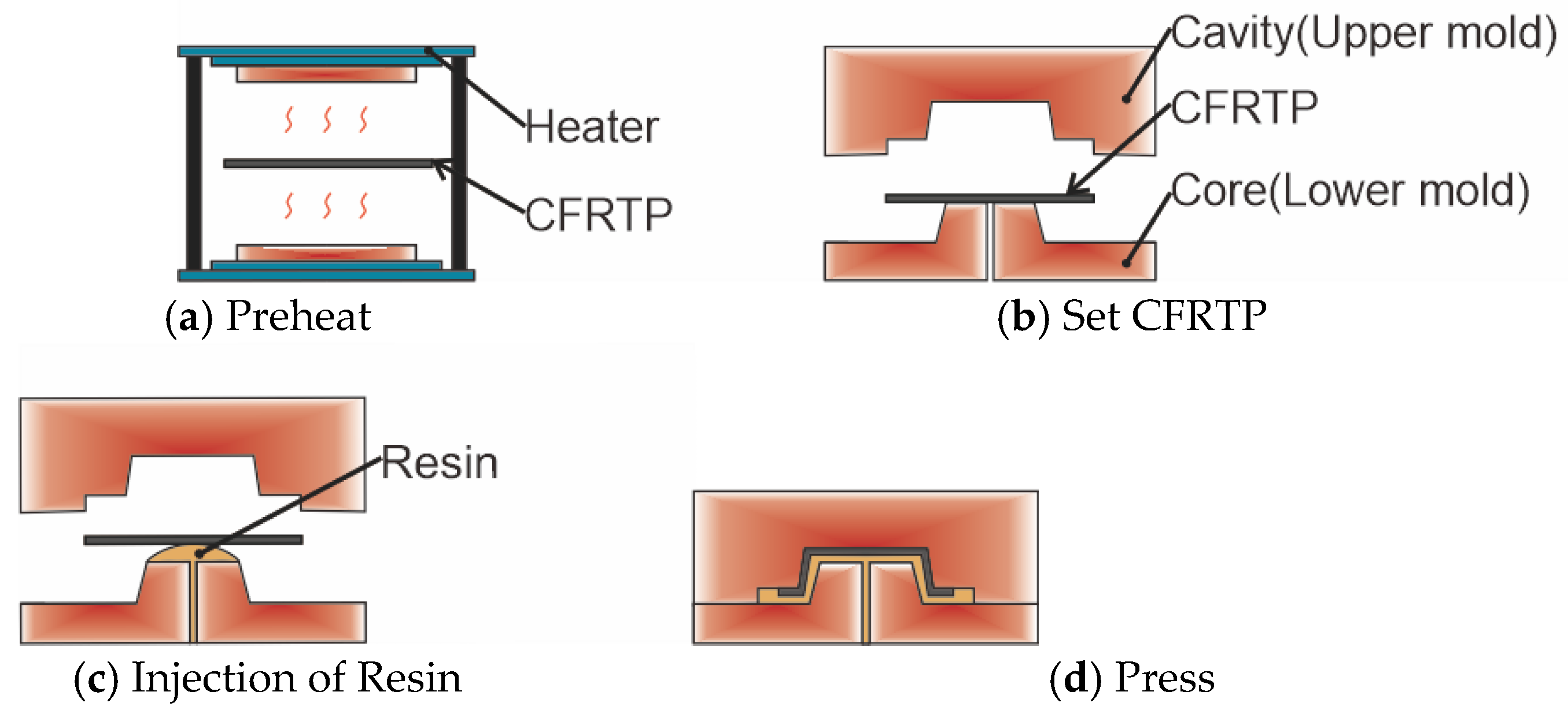
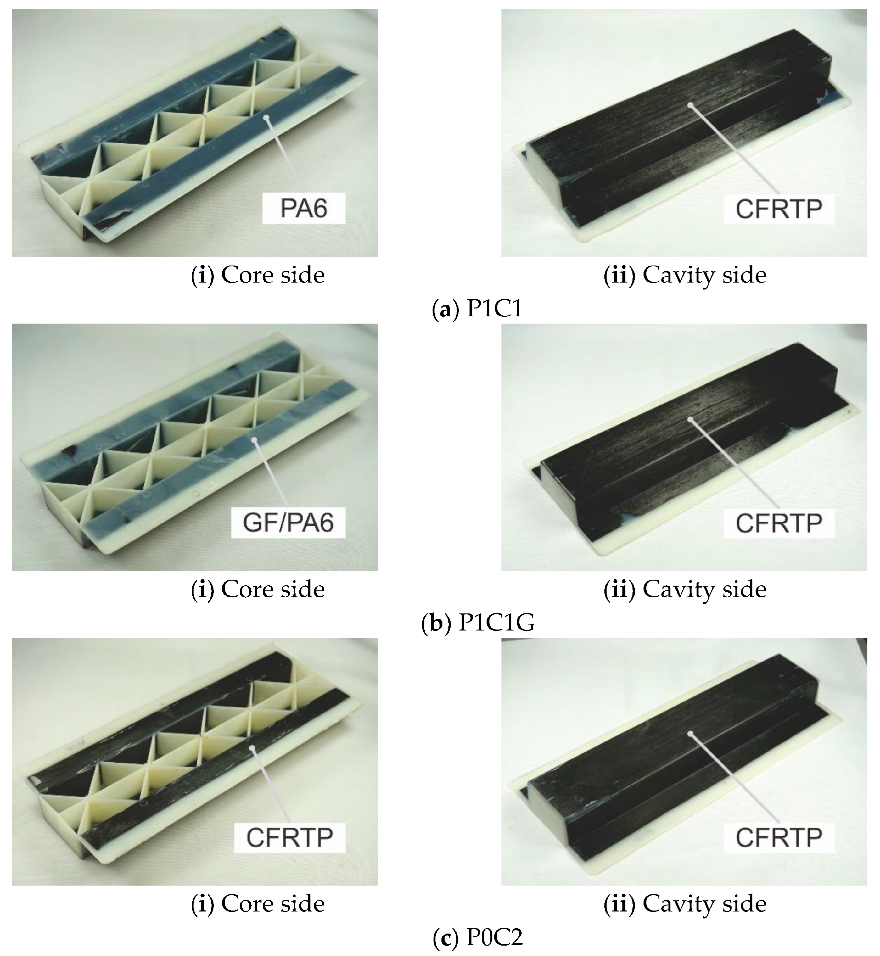
2.1. Materials and Method of Fabricating Hat-Shaped Parts

The CFRTP laminates used as the surface material of the outer shell of the hat-shaped parts were a CF/Phenoxy prepreg (CF: TR50S-15L, Vf: 50%, area weight: 264 g/m2, KURABO INDUSTRIES Ltd., Osaka, Japan) made of unidirectional carbon fiber impregnated with phenoxy resin. Injection materials supplied to the ribs and flange of the hat-shaped parts were PA6 resin (1015B, melting point: 225 °C, tensile modulus: 2.9 GPa, Ube Industries Ltd., Tokyo, Japan) and glass fiber-reinforced PA6 resin (1015GC6, melting point: 225 °C, tensile modulus: 9.3 GPa, Vf: 15–17%, Ube Industries Ltd., Tokyo, Japan). The CFRTP laminates were laminated in a configuration of [0°/90°/0°]2 and [0°/90°/0°]4 to achieve a thickness of 1 mm or 2 mm and pressed at a forming temperature of 180 °C, a press pressure of 4 MPa, and a holding time of 300 s. An injection-press hybrid molding machine (STIP05-05, SATOH MACHINERY WORKS Co., Ltd., Nagoya, Japan), which combines an injection molding machine and a press molding machine, was used to mold hat-shaped parts. Figure 1 shows the molding method for hat-shaped parts. The CFRTP laminate was heated and melted (Figure 1a) in advance in a contact heater (TH-5, Leibrock, Pirmasens, Germany) set at 180 °C and placed in a mold maintained at 150 °C (Figure 1b). Next, neat PA6 resin or glass fiber-reinforced PA6 resin was injected from the bottom of the mold (Figure 1c). Finally, the mold was closed and compressed (Figure 1d) to fabricate the hat-shaped molded parts shown in Figure 2. In this study, three types of hat-shaped parts were fabricated. The composition of the surface material and resin layer is shown in Table 1, and a schematic drawing is shown in Figure 3. P0C1 and P0C1G, without a resin layer, could not be fabricated with the existing molds, so they were used only for FEM analysis, as discussed in Section 2.4. P means PA6, C means CFRTP laminate, G means glass fiber, and the number after the code indicates the thickness. P1C1 and P1C1G, which used a 1 mm thick CFRTP laminate placed on the top surface of the outer shell, had a 1 mm thick neat PA6 resin layer or glass fiber-reinforced PA6 resin layer by injection molding; P0C2 used a CFRTP laminate with 2 mm thickness for the outer shell.

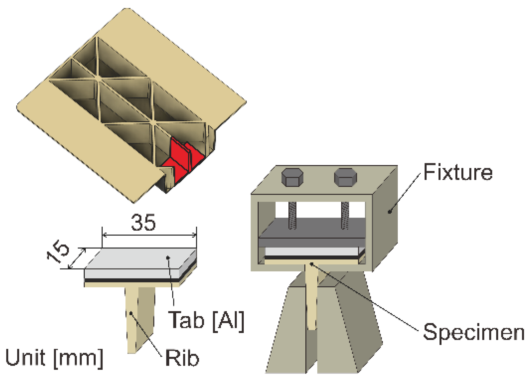
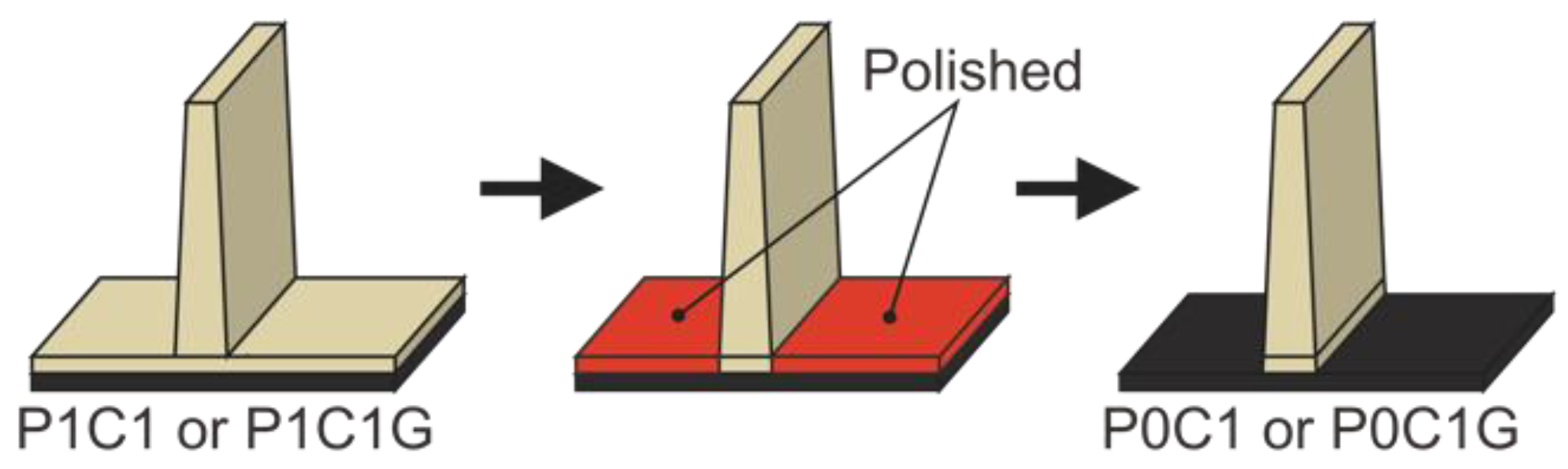
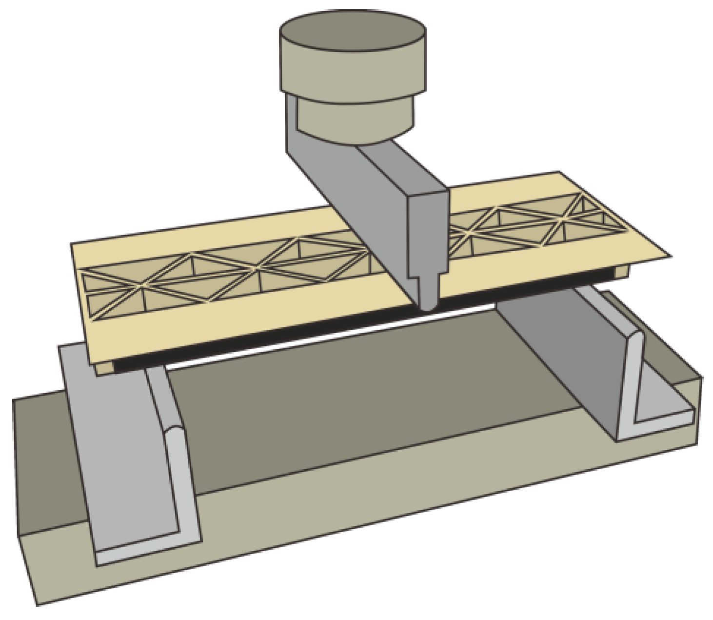
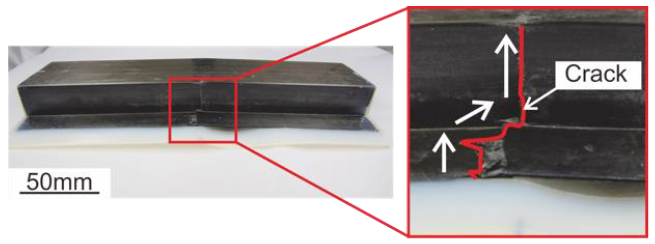
2.2. T-Shaped Tensile Tests

The bond strength at the rib root of each hat-shaped part was evaluated by a tensile test using a universal testing instrument (5566, Instron, Norwood, MA, USA) with a T-shaped specimen cut out, as shown in Figure 4. With reference to the previous studies [12,13,20], T-shaped tensile tests were conducted. T-shaped tensile tests were also performed on specimens of P1C1 and P1C1G in which the resin layer at the rib root was removed using abrasive paper, as shown in Figure 5. These specimens are called P0C1 and P0C1G, respectively. To reduce displacement in the direction of tensile loading, aluminum tabs were bonded to the laminates of the test specimens using epoxy adhesive. The displacement speed was set to 1.7 × 10⁻⁵ m/s (1.0 mm/min), and the bond strength was calculated by dividing the maximum load in the obtained load–displacement curve by the cross-sectional area, without considering the R at the rib root, regardless of the failure position. The cross section of each specimen was observed using a digital microscope (VHX-5000, Keyence, Osaka, Japan).

2.3. Three-Point Bending Tests of Hat-Shaped Parts

The mechanical properties of each hat-shaped part were evaluated by a three-point bending test using a universal testing instrument (Autograph AGX-250 kN, Shimadzu Corporation, Kyoto, Japan) with the surface material on the tensile side, as shown in the schematic diagram in Figure 6. The displacement speed was set to 5.3 × 10⁻⁵ m/s (3.2 mm/min), the span length of the support was 240 mm, and the slope of the obtained load–displacement curve from the time when the hat-shaped part was loaded to the displacement of 0.96 mm was calculated as the stiffness of the entire part. The bending behavior of each hat-shaped part during the test was observed using a digital video camera (FDR-AX45, SONY, Tokyo, Japan).

2.4. Three-Point Bending FEM Analysis of Hat-Shaped Parts

FEM analysis was performed by Solid Mechanics (structural mechanics module) using the COMSOL Multiphysics® (Stockholm, Sweden) simulation software. An example of an FEM model is shown in Figure 7. The mesh was generated with tetrahedral elements. The displacement in the –Z direction was applied to the FEM model at the line segment assuming the indenter on the core side, and the displacement in the Z direction was constrained at the two-line segments assuming the support on the cavity side. The shapes of the FEM models are the same as those of P1C1, P1C1G, and P0C2 fabricated in Section 2.1, and structures are shown in Figure 8a,b. A convex surface material with a thickness of 2 mm was divided into 1 mm sections; for P1C1 and P1C1G, the core side was set as the resin layer and the cavity side was set as the laminate. In P0C2, both the core and cavity sides were set as the laminate. To evaluate the effect of the resin layer at the rib root on the mechanical properties, analyses were also performed for P0C1 and P0C1G with the resin layer at the rib root removed, as shown in Figure 8c. Table 2 shows the material properties of each material used in the FEM model. Young’s modulus of PA6 resin, glass fiber-reinforced PA6 resin, and CFRTP laminate in the Z direction was evaluated by load–unload tests using a dynamic ultra micro hardness tester (DUH-211, Shimadzu Corporation, Kyoto, Japan). Young’s modulus of CFRTP laminates in the X and Y directions was calculated from displacements obtained by FEM analysis of the tensile tests using an FEM model of a strip specimen complying with JIS K 7164. The FEM model was created using the same structure as the CFRTP laminate explained in Section 2.1. Other material properties were based on catalog values [21,22,23,24]. In this study, the reaction force and displacement acting on the line segment assuming an indenter were obtained by three-point bending FEM analysis; the stiffness was calculated as shown in Section 2.3 and compared with the experimental values. The principal stress distribution for the cross section of the parts shown in Figure 9 and the principal strain distribution for the sides of the parts were obtained, and the specific stiffness was calculated by dividing the stiffness by the density.

2.5. Cost Evaluation of Hat-Shaped Parts

The costs of the injection and surface materials used to fabricate each hat-shaped part are the values shown in Table 3. These costs were our purchase prices. The molded part costs were calculated using the material costs shown in Table 3, using the volumes of the injection part, laminate, and resin layer calculated by CAD software and the density of the materials. The results of the cost calculations for each hat-shaped part are shown in Table 4. In this study, the cost of materials only was evaluated, without considering labor, equipment, or molding costs, and the relationship between the specific stiffness calculated by FEM analysis and the cost of each hat-shaped part was evaluated.

3. Results and Discussion

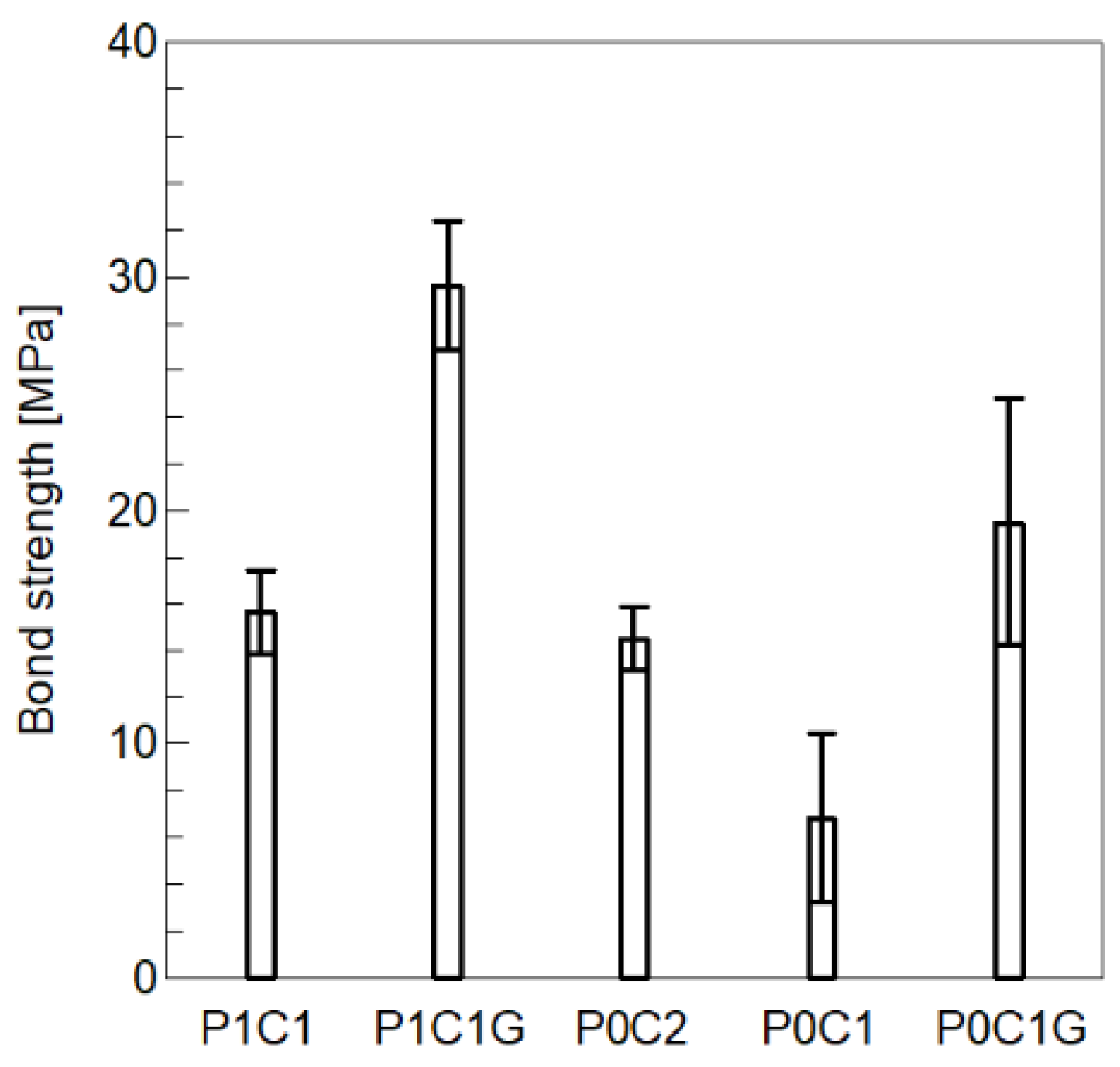
3.1. T-Shaped Tensile Test

Figure 10 shows the results of the observation of the molded P1C1 and P1C1G from the core side, respectively. Whitened areas were observed where the CFRTP laminate and the resin layer appeared to be peeling off. For clarity, the peeled areas are shown in red in the right-side figures of Figure 10. Although for P1C1, which used neat PA6 resin as the injection material, a peeled area was observed, no peeling was observed for P1C1G, which used glass fiber-reinforced PA6 resin as the injection material. Cross-sectional observations of the cut specimens of P1C1 and P0C2 are shown in Figure 11. P0C2, which used a 2 mm thick CFRTP laminate, showed that the press pressure caused the laminate to flow into the ribs in contrast to P1C1, which had a resin layer. Although not shown here, P1C1G, P0C1, and P0C1G, like P1C1, showed no laminate flow into the ribs.
Figure 12 shows the results of the bond strength at the rib roots obtained from the T-shaped tensile test. The bond strengths of P1C1 and P1C1G with a resin layer at the rib root were 129% and 52% higher than those of P0C1 and P0C1G without a resin layer, respectively. The bond strength of P1C1 was not significantly different from that of P0C2. The bond strengths of P1C1G and P0C1G using glass fiber-reinforced PA6 resin as the injection material were 90% and 186% higher than those of P1C1 and P0C1 using neat PA6 resin, respectively. In general, the stress was concentrated at the rib roots. In the case of P1C1 and P1C1G, which had a resin layer, the stress dispersed at the interface due to the resin layer. As a result, P1C1 and P1C1G with a resin layer at the rib roots showed higher bond strengths than P0C1 and P0C1G without a resin layer. Previously, the authors reported that, in hybrid molding, the more the laminate flows into the ribs, the higher the bond strength is [12,13]. In this study, P0C2, which used 2 mm thick CFRTP laminates and did not have a resin layer, increased the bond strength due to the inflow into the ribs of the laminate. Therefore, it is considered that the bonding strength of P0C2 was equivalent to that of P1C1 with a resin layer. The mold shrinkage rate [21,22] of the materials used in injection molding was 1.4% in the machine direction and 1.5% in the transverse direction for the neat PA6 resin, while the glass fiber-reinforced PA6 resin had lower values of 0.2% in the machine direction and 0.7% in the transverse direction. As shown in Figure 10b, the use of glass fiber-reinforced PA6 resin as the injection material prevented peeling of the bonding area due to its low mold shrinkage rate. It was reported that, in the case of joints between injection materials and metals, the smaller the amount of peeling in the bonding area, the higher the bond strength is and there is a correlation between the two [15]. These results suggest that P1C1G, which had a lower mold shrinkage rate, can be used to mold parts that exhibit higher bond strength than P1C1.

3.2. Three-Point Bending Tests of Hat-Shaped Parts

Some examples of load–displacement curves obtained from three-point bending tests are shown in Figure 13. The stiffness and maximum load calculated from these results are shown in Figure 14. The stiffness of P1C1G was 70% higher than that of P1C1 and not significantly different from that of P0C2. The maximum load of P0C2 was 85% higher than that of P1C1, and the maximum load of P1C1G was 74% higher than that of P1C1.
The use of glass fiber-reinforced PA6 resin, which has a high Young’s modulus, in the injection material showed that P1C1G exhibited higher stiffness than P1C1. A study on the bending properties of hat-shaped parts reported that the thicker the laminate, the higher the stiffness [25]; in this study, P0C2, with a thicker laminate of 2 mm CFRTP, showed higher stiffness than P1C1. Figure 15 shows a side observation of P1C1 after the three-point bending test; the white arrows indicate the direction of crack propagation. At maximum load, a crack was observed in the CFRTP laminate at the back of the flange, followed by crack propagation to the side of the part. Although not shown here, cracks in the laminates were observed in P1C1G and P0C2 as well as in P1C1. Figure 14 suggests that the use of a high-strength laminate for the surface material resulted in a higher maximum load for P0C2 than that for P1C1. As shown in Figure 15, the laminate cracked around 3.5 mm displacement, showing the maximum load in both P1C1 and P1C1G. However, there was a significant difference in the maximum load of P1C1 and P1C1G. The reasons for this difference are discussed in detail in Section 3.3.

3.3. Three-Point Bending FEM Analysis of Hat-Shaped Parts

The stiffness of each hat-shaped part obtained by FEM analysis is shown in Figure 16 with the experimental values. For P1C1G and P0C2, the analytical values were within the standard deviation, showing that the modeling performed with excellent accuracy. On the other hand, for P1C1, the analytical value was not within the standard deviation of the experimental values and was high. As shown in Figure 10a, peeling between the CFRTP laminate and the resin layer on the surface at P1C1 is considered to be the one reason for these lower experimental values. Figure 17 shows the observed bending behavior of P1C1 at a displacement of 0.96 mm after loading in a three-point bending test. The resin layer was observed to have peeling at the flange just below the indenter. In the FEM model of P1C1, the bonding conditions between the laminate and the resin layer were not considered, which may have lowered the stiffness.
The principal stress distributions and the principal strain distributions of each model obtained by FEM analysis are shown in Figure 18. In the principal stress distribution of P1C1G and P0C1G using glass fiber-reinforced PA6 resin as the injection material, we observed higher stress in the ribs just below the indenter than in P1C1, P0C2, and P0C1 using neat PA6 resin. The cause of the significant difference in the maximum loads for P1C1 and P1C1G in Section 3.2 may be due to the glass fiber-reinforced PA6 resin, which increased the stiffness of the ribs and prevented deformation. In the principal strain distribution of P0C2, P0C1, and P0C1G, which had no resin layer, the strain was concentrated at the place where the ribs were located. On the other hand, P1C1 and P1C1G with the resin layer were observed to prevent the concentration of strain. The resin layer is considered to have dispersed the load applied to the interface and prevented the concentration of strain.
The specific stiffness calculated by dividing the stiffness of each hat-shaped part by the density is shown in Figure 19. The specific stiffness of P1C1 and P1C1G with a resin layer at the rib root was 38% and 42% higher than that of P0C1 and P0C1G without a resin layer, respectively. The resin layer is considered to have increased the sectional secondary moment, resulting in high specific stiffness. Therefore, if the wall thickness can be expanded, a molded part with excellent stiffness can be fabricated by adding a resin layer at the rib root. In this study, the P1C1G with a 1 mm thick CFRTP laminate on the top surface of the outer shell and a 1 mm glass fiber-reinforced PA6 resin layer by injection showed the highest specific stiffness.
In this study, only the stiffness was obtained by the FEM models. The next step would be to construct the FEM model for fracture analysis. In this case, the Cohesive Zone Model (CZM) in the FEM analysis would be one solution to obtain more accurate simulation results [20,26].

3.4. Cost Evaluation of Hat-Shaped Parts

The relationship between material cost and specific stiffness for each hat-shaped part calculated by FEM analysis is shown in Figure 20. The cost of P1C1 and P1C1G with a resin layer at the rib root was almost the same as that of P0C1 and P0C1G without a resin layer. The specific stiffness of P1C1 and P1C1G was 38% and 42% higher than that of P0C1 and P0C1G, respectively. By adding a resin layer to the rib roots, molded parts with excellent specific stiffness can be fabricated at a small increase in cost. Among these, P1C1G, which had a 1 mm thick CFRTP laminate on the top surface of the outer shell and a 1 mm glass fiber-reinforced PA6 resin layer by injection molding, achieved a 7% higher specific stiffness at a 47% lower cost than P0C2, which used a 2 mm thick CFRTP laminate for the outer shell.

4. Conclusions

In this study, CFRTP hat-shaped parts with neat PA6 or glass fiber-reinforced resin layers at the rib roots were fabricated by press-injection hybrid molding. T-shaped tensile and three-point bending tests at the rib root were performed to assess the bond strength between the surface material and the ribs and to clarify their effects on stiffness. Furthermore, a three-point bending FEM analysis was performed to clarify the effect of the resin layer at the rib roots on the mechanical properties and the relationship between material cost and mechanical properties. The investigation yielded the following conclusions:
  • In T-shaped tensile tests at the rib roots, molded parts with neat and fiber-reinforced resin layers at the rib roots showed 129% and 52% higher bond strengths than those without resin layers, respectively. The use of glass fiber-reinforced PA6 resin showed a lower molding shrinkage rate, suggesting that it prevents peeling of the bonded area, resulting in higher bond strength than that of the neat PA6 resin.
  • In the CFRTP hat-shaped parts with a resin layer at the rib root, the use of glass fiber-reinforced PA6 resin as an injection material enables the fabrication of a molded part that shows the same stiffness as that of a molded part using a 2 mm thick CFRTP laminate for the outer shell.
  • The three-point bending FEM analysis of a CFRTP hat-shaped part showed that the addition of a resin layer prevents the concentration of strain where the ribs of the surface material are located. The model with the use of a 1 mm thick CFRTP laminate for the outer shell and glass fiber-reinforced PA6 resin as the injection material showed the best specific stiffness in this study.
  • By adding a resin layer to the rib root, molded parts with excellent specific stiffness can be fabricated with a small increase in cost. A model with a resin layer using glass fiber-reinforced PA6 resin as the injection material showed low cost and excellent specific stiffness.

Author Contributions

Conceptualization, K.T.; data curation, M.T.; funding acquisition, K.T.; investigation, M.T.; methodology, K.T.; project administration, K.T.; resources, K.T.; supervision, K.T.; validation, K.T. and M.T.; visualization, M.T.; writing—original draft, M.T.; writing—review and editing, K.T. All authors have read and agreed to the published version of the manuscript.

Funding

This research was partially supported by Individual Research Allowances of Doshisha University.

Data Availability Statement

Data are contained within the article.

Conflicts of Interest

The authors declare no conflicts of interest.

References

  1. Ureshino, Y. Weight reduction and joining Technology for multi-material automobile. J. Surf. Finish. Soc. Jpn. 2022, 73, 380–383. [Google Scholar] [CrossRef]
  2. Ishikawa, T. Overview of carbon fiber reinforced composites (CFRTP) applications to automotive structural parts,-focused on thermoplastic CFRP-. J. Jpn. Soc. Precis. Eng. 2015, 81, 489–493. [Google Scholar] [CrossRef]
  3. Wan, Y.; Takahashi, J. Developed of carbon fiber-reinforced thermoplastics for mass-produced automotive applications in Japan. J. Compos. Sci. 2021, 5, 86. [Google Scholar] [CrossRef]
  4. Terada, K. Carbon fiber reinforced thermo plastics-currently, applications and forecast. J. Jpn. Soc. Precis. Eng. 2015, 81, 485–488. [Google Scholar] [CrossRef]
  5. Lee, J.M.; Kim, B.M.; Ko, D.C. Multi-material forming using DP780 and CFRTP. Procedia Manuf. 2018, 15, 1716–1721. [Google Scholar] [CrossRef]
  6. Guo, Q.; Xiao, B.; Ohsawa, I.; Fujita, M.; Takahashi, J. Numerical analysis and optimization of CFRTP hat-stiffened structure. In Proceedings of the ECCM18—18th European Conference on Composite Materials, Athens, Greece, 25–28 June 2018; pp. 1–8. [Google Scholar]
  7. Limaye, M.; Pradeep, S.A.; Kothari, A.; Savla, S.; Agha, A.; Pilla, S.; Li, G. Thermoforming process effects on structural performance of carbon fiber reinforced thermoplastic composite parts through a manufacturing to response pathway. Compos. Part B 2022, 235, 109728. [Google Scholar] [CrossRef]
  8. Fiorotto, M.; Lucchetta, G. Experimental investigation of a new hybrid molding process to manufacture high-performance composites. Int. J. Mater. Form. 2013, 6, 179–185. [Google Scholar] [CrossRef]
  9. Kang, T.-H.; Lee, J.-W.; Kim, J.-H.; Ahn, T.-M.; Ko, D.-C. Design of center pillar with composite reinforcements using hybrid molding method. Material 2021, 14, 2047. [Google Scholar] [CrossRef]
  10. Ohishi, M.; Ohtani, A.; Nakai, A. Effect of heating condition for prepreg sheet and injection resin on interfacial properties between prepreg and injection part in hybrid molding. Seikei-Kakou 2017, 29, 135–141. [Google Scholar] [CrossRef]
  11. Asanuma, N. Applying direct injection molding process and hybrid molding system to CFRP molding. Seikei-Kakou 2015, 27, 89–93. [Google Scholar] [CrossRef]
  12. Tanaka, K.; Tokura, D.; Katayama, T.; Ishikawa, T.; Tomioka, M. Evaluation of mechanical property of press and injection hybrid molded CF/PA6 using cut prepreg sheets. J. Soc. Mater. Sci. 2016, 65, 713–720. [Google Scholar] [CrossRef]
  13. Tanaka, K.; Harada, Y.; Katayama, T.; Ishikawa, T.; Tomioka, M. Press and injection hybrid using CF/PP unidirectional slit prepreg and evaluation of boding strength at rib root. J. Soc. Mater. Sci. 2016, 65, 721–726. [Google Scholar] [CrossRef]
  14. Wan, Y.; Takahashi, J. Tensile and compressive properties of chopped carbon fiber tapes reinforced thermoplastics with different fiber lengths and molding pressures. Compos. Part A 2016, 87, 271–281. [Google Scholar] [CrossRef]
  15. Seto, M.; Tanaka, H.; Katayama, M.; Itakura, M.; Yamabe, M. Influence of reinforced fiber on joining strength in metal-resin joining injection molded products. Seikei-Kakou 2016, 28, 427–433. [Google Scholar] [CrossRef]
  16. Akkerman, R.; Bouwman, M.; Wijskamp, S. Analysis of the Thermoplastic Composite Overmolding Process: Interface Strength. Front. Mater. 2020, 7, 27. [Google Scholar] [CrossRef]
  17. Paramasivam, A.; Timmaraju, M.V.; Velmurugan, R. Influence of Preheating on the Fracture Behavior of Over-Molded Short/Continuous Fiber Reinforced Polypropylene Composites. J. Compos. Mater. 2021, 55, 4387–4397. [Google Scholar] [CrossRef]
  18. Hartley, W.D.; McCann, J.; Davis, S.; Hocker, T.; Bobba, S.; Verghese, N.; Bajaj, D.; Yu, H.Z.; Dillard, D.A. Fracture Characterization of Composite adhesion. J. Thermoplast. Compos. Mater. 2022, 35, 977–997. [Google Scholar] [CrossRef]
  19. Jiang, Q.; Takayama, T.; Nishioka, A. Impact energy dissipation and quantitative models of injection molded short fiber-reinforced thermoplastics. Polymers 2023, 15, 4297. [Google Scholar] [CrossRef] [PubMed]
  20. Giusti, R.; Lucchetta, G. Cohesive Zone Modeling of the Interface Fracture in Full-Thermoplastic Hybrid Composites for Lightweight Application. Polymers 2023, 15, 4459. [Google Scholar] [CrossRef] [PubMed]
  21. UBE Corporation Website. Available online: https://ube.es/wp-content/uploads/2021/12/TDS_UBE-NYLON-1015B_Injection.pdf (accessed on 18 July 2023).
  22. UBE Corporation. Available online: https://www.ube.com/contents/jp/chemical/nylon/chemical_injection/1015gc6.html (accessed on 18 July 2023).
  23. Mitsubishi Chemical Group Corporation. Available online: https://www.m-chemical.co.jp/carbon-fiber/product/tow/ (accessed on 18 July 2023).
  24. Gabriel Phenoxies, Inc. Available online: https://www.gabrielchem.com/wp-content/uploads/GPI-SDS-US-PHENOXY-RESIN-PELLETS-Version-5.pdf (accessed on 18 July 2023).
  25. Dhaliwal, G.S.; Newaz, G.M. Experimental and numerical investigation of flexural behavior of hat sectioned aluminum/carbon fiber reinforced mixed material composite beam. Compos. Part B Eng. 2020, 182, 107642. [Google Scholar] [CrossRef]
  26. Ghabezi, P.; Farahani, M. Effects of Nanoparticles on Nanocomposites Mode I and II Fracture: A Critical Review. Rev. Adhes. Adhes. 2017, 5, 414–435. [Google Scholar] [CrossRef]
Figure 1. Molding process of injection-press hybrid molded part.
Jcs 08 00056 g001
Figure 2. Molded hat-shaped parts.
Jcs 08 00056 g002
Figure 3. Schematic drawing of hat-shaped parts. (the red square in the figure is a magnified view of the rib root).
Jcs 08 00056 g003
Figure 4. Schematic drawing of T-shaped specimen and tensile test.
Jcs 08 00056 g004
Figure 5. Removal process of the resin layer at the rib root.
Jcs 08 00056 g005
Figure 6. Schematic drawing of three-point bending test.
Jcs 08 00056 g006
Figure 7. Schematic drawing of FEM model for P1C1, P1C1G.
Jcs 08 00056 g007
Figure 8. Composition of FEM models.
Jcs 08 00056 g008
Figure 9. Cross-sectional observation area of FEM model.
Jcs 08 00056 g009
Figure 10. Molded parts after the eject process and their schematic diagrams.
Jcs 08 00056 g010
Figure 11. Magnified cross-sectional view of T-shaped specimens.
Jcs 08 00056 g011
Figure 12. Tensile strength of molded parts obtained by T-shaped tensile tests. (N = 5, mean ± S.D).
Jcs 08 00056 g012
Figure 13. Load–displacement curve of three-point bending tests.
Jcs 08 00056 g013
Figure 14. Stiffness and maximum load of molded parts obtained by three-point bending tests. (N = 5, mean ± S.D).
Jcs 08 00056 g014
Figure 15. Observation of the side of P1C1 after three-point bending tests (the red square in the figure is a magnified view of the crack area).
Jcs 08 00056 g015
Figure 16. Stiffness of experimental and analytical results.
Jcs 08 00056 g016
Figure 17. Observation of bending behavior of P1C1 (the red square in the figure is a magnified view of peeled area) (displacement = 0.96 mm).
Jcs 08 00056 g017
Figure 18. Analyzed principal stress and principal strain distributions of FEM models (displacement = 0.96 mm).
Jcs 08 00056 g018
Figure 19. Specific stiffness of FEM models.
Jcs 08 00056 g019
Figure 20. Relationship between material cost and specific stiffness.
Jcs 08 00056 g020
Table 1. Composition of hat-shaped parts.
Resin Layer [mm]CFRTP Laminate [mm]ExperimentFEM Analysis
PA6GF/PA6
P1C11-1
P1C1G-11
P0C2--2
P0C1--1-
P0C1G--1-
Table 2. Material properties.
PropertyYoung’s Modulus [GPa]Shear Modulus [GPa]Poisson RatioDensity [kg/m3]
Material EXEYEZGXGYGZ
PA62.3 0.31140 [21]
GF/PA63.7 0.31360 [22]
CFRTP laminate79401.830150.70.31505 [23,24]
Table 3. Cost of materials.
MaterialCost [yen/kg]
PA60.60 × 103
GF/PA61.2 × 103
CF/Phenoxy prepreg29 × 103
Table 4. Cost of molded parts.
Molded PartCost [yen]
P1C12.0 × 103
P1C1G2.1 × 103
P0C23.9 × 103
P0C12.0 × 103
P0C1G2.1 × 103
Disclaimer/Publisher’s Note: The statements, opinions and data contained in all publications are solely those of the individual author(s) and contributor(s) and not of MDPI and/or the editor(s). MDPI and/or the editor(s) disclaim responsibility for any injury to people or property resulting from any ideas, methods, instructions or products referred to in the content.

