1. Introduction
Composite materials are well known for their extraordinary characteristics in terms of specific mechanical performances, especially when continuous carbon fibers are used as reinforcement. For such reasons, Carbon-Fiber-Reinforced Polymers (CFRPs) exhibit constant growth in applications where lightness and strength are the main targets to be fulfilled [
1,
2,
3,
4,
5,
6,
7]. In order to create strong composite structures, multilayer laminates in CFRP can be used, obtained by laying up different pre-impregnated layers until the desired thickness is reached. The layers deposition must be accurately performed in order to reach the desired performances. The lay-up process can be performed manually [
8,
9] or by means of automated systems [
10]. Depending on the layer arrangement, different types of laminates can be obtained. The maximum mechanical properties are obtained by manufacturing unidirectional composites, in which the continuous carbon fibers are parallelly oriented and in the same direction [
11]. Unfortunately, this configuration can be used in very few applications because the properties are optimized only in the longitudinal direction of the fibers. Therefore, it is not an optimal configuration for applications in which combined loadings are applied along different directions. To overcome such drawbacks, cross-ply laminates, in which fibers are oriented at 0° and 90°, can be stacked since they can provide excellent mechanical performances in more than one direction. Furthermore, a stacking sequence of 0°, 45°, 90°, −45°, 0° can be used to make the material more orthotropic, even though the high mechanical properties typical of the unidirectional laminates cannot be achieved [
11]. In addition, fibers can also be oriented along two perpendicular directions obtaining bidirectional fabrics. They are characterized by a warp and weft, in which the weave type determines how often the transverse (0/90°) strands of fibers in fabrics are mutually interleaved. Composite woven fabrics offer many advantages in terms of deformation capability, dimensional stability, good conformability, damage tolerance, easy handling, and low fabrication costs as compared to unwoven-fabric composites [
12]. Different architectures can be manufactured, such as plain, satin, and twill weaves. The different fiber architectures can significantly affect the mechanical properties of the fiber-reinforced composites. For this reason, the type of fabric reinforcement must be carefully chosen, considering the application and the mechanical stresses that the part will have to withstand [
13]. Unfortunately, woven fabric composites are characterized by drawbacks leading to a reduction in the mechanical properties as compared to unidirectional laminates. Specifically, the fibers undulation, or crimping, causes a misalignment of the fibers outside the fabric plane, and a consequent decrease in both stiffness and strength of the composite materials [
14,
15,
16,
17,
18]. As a matter of fact, failure of fabric composites generally begins at lower strain values than those at which unidirectional composites fail. Earlier crack initiation in textile composites does not immediately result in catastrophic failure, but it can affect the component performance. Many researchers have dealt with these issues to evaluate the different damage methods as a function of the process and material parameters [
19,
20,
21]. Specifically, it was noted that the areal weight (AW) of the fabric, that is the amount (mass) of fibers within an area unit of the fabric, is a fundamental parameter that affects the fabric failure mechanisms, since laminates with a low AW are characterized by a failure involving fibers, while a laminate with a high AW value undergoes delamination. Mateusz Koziol [
13] demonstrated that the increase in AW leads to an increase both in tensile strength and elasticity modulus, and a decrease in the deformability of laminates reinforced with different fiber typologies. However, only 200 g/m
2 carbon fabric laminates were analyzed. Di Bella et al. [
22] studied the effect of the AW on the mechanical properties of bidirectional-flax-fabrics-reinforced composites; they demonstrated that the flexural properties decrease when the AW increases because of the delamination effect. Recently thin-ply composites have received an increasing attention due to their high mechanical performances [
23,
24]. Unfortunately, few studies concerning the effect of fabric AW on the mechanical properties of composite laminates in carbon-fiber-reinforced polymers are available in scientific literature.
In this framework, the present investigation aims at studying the influence of fabric AW on the performances of laminates in carbon-fiber-reinforced polymers. To this purpose, three different pre-impregnated 2 × 2 twill weaves in CFRP, characterized by different AW values of 380 g/m2, 630 g/m2, and 800 g/m2 and supplied by company operating in automotive field, were used. These fabrics are the most employed in the automotive sector, specifically in manufacturing of structural components, because they are characterized by high drapability and limited crimping. In order to obtain the desired final thickness of laminates, a different number of plies was laid-up, i.e., three layers of fabric with the highest AW investigated, four layers with the 630 g/m2 weave, and six plies of fabric with the lowest AW. Samples were cut from the composite laminates after curing. The performances of the composites were evaluated by means of void quantities analysis, uniaxial tensile, and in-plane shear tests to identify the configuration that led to optimal mechanical performance. The effect of the fabric AW on the response of the CFRP laminates was investigated.
The paper is organized as follows: after the introduction,
Section 2 presents the description of the materials investigated and the methods applied. In
Section 3, the results are shown and discussed. Finally, the main conclusions are summarized.
3. Results and Discussion
Figure 3 shows the light optical microscopies of the longitudinal sections and external flat surfaces of composite laminates after curing obtained by laying-up 2 × 2 twill weaves with different AW values. It can be observed that weaving necessarily introduces a fiber misalignment (crimp) inside the composite that can affect the mechanical performances of laminates and the failure mechanisms. Irrespective of the AW taken into account, the twill architectures are characterized by a quasi-elliptical shape. Furthermore, it can be seen that the composite laminates are manufactured using a lower number of fabrics layers with increasing the AW factor to obtain the desired final thickness of composite laminate equal to 2.5 mm. A more lenticular fiber shape appears as the weave with the lowest AW value is considered (
Figure 3a) as compared to the other two fabrics with an AW of 630 g/m
2 and 800 g/m
2 (
Figure 3b,c), which show different stacking patterns.
The presence of voids into laminates strongly reduces the material strength. Moreover, voids affect the humidity absorption and other properties such as chemical and physical degradation of fibers. As far as the evaluation of the reinforcement, resin, and void contents is concerned, results of the resin digestion test are shown in
Table 2. Values are reported as a percentage by weight (%
w/
w) or by volume (%
v/
v).
It can be seen that the fabric characterized by the lowest AW value shows the lowest void content in percentage, demonstrating that the lightest weave can be subjected to a more efficient compaction operation, while the fabric with an AW of 630 g/m2 presents the higher percentage of voids.
In order to evaluate the effect of the fabric AW on the mechanical performances of CFRP composite laminates, tensile and in-plane shear response tests were carried out at room temperature.
Figure 4 shows typical stress vs. strain curves provided by tensile tests on CFRP laminates after curing. The curves are characterized by a linear elastic behavior, also in the larger displacement region until fracture, according to the results shown by Forcellese et al. [
26] on unidirectional laminates in CFRP and by Di Bella et al. [
22] on bidirectional-fabrics-reinforced composites.
As far as the fabric AW is concerned, it can be observed that, for a given strain level, a decrease in AW leads to an increase in strength and stiffness, according to the results shown by Zhou et al. [
4]. The average values of ultimate tensile strength, elastic modulus, and ultimate elongation are summarized in
Table 3.
Fabrics with the lowest AW led to the obtaining laminates characterized by ultimate tensile strength, ultimate elongation, and elastic modulus values that are 34.7%, 15.8%, and 14.3%, respectively, higher than those realized using a fabric AW of 630 g/m2, and 56.9%, 23.7%, and 26.6% higher, respectively, in respect of the fabric AW of 800 g/m2. This means that the reduction in weight of fiber per unit area of the fabric significantly improves the load bearing capability and the strain-to-failure of the composite material.
The effect of fabric AW on the in-plain shear properties of laminates is similar to that observed for the tensile properties. To this purpose,
Figure 5 shows typical shear stress vs. shear strain curves for the different fabric AW specimens.
It can be noted that the composite laminate manufactured by laying-up plies of 380 g/m
2 exhibits higher in-plane shear stress than those obtained using plies with an AW of 630 g/m
2 and 800 g/m
2; specifically, the laminate with the AW of 380 g/m
2 shows a maximum shear stress value 44.7% and 55.4% higher than that obtained using twill fabrics of 630 g/m
2 and 800 g/m
2. Such behavior can be attributed to the different fiber alignment. As a matter of fact, the fibers interweaving in the fabric with AW of 630 g/m
2 and 800 g/m
2 are characterized by more noticeable and pronounced undulations than those exhibited by fabric with AW of 380 g/m
2, as shown in
Figure 3, resulting in different fabric mechanical behaviors. Instead, the in-plane shear chord modulus of elasticity is higher for the AW of 630 g/m
2 than for the AW 380 g/m
2 and 800 g/m
2. As a matter of fact, for low shear strain values, the slope of the curve related to the AW of 630 g/m
2 is higher than that obtained for AW of 380 g/m
2. Such a slope tends to decrease as the shear strain increases; in particular, after a shear strain of 5000 µε, the slope of the curve related to the fabric AW of 380 g/m
2 becomes higher than that at 630 g/m
2. On the other hand, the curve relative to the fabric of 800 g/m
2 is always below the other two curves, proving that it is characterized by values of in-plane shear stress and in-plane shear chord modulus lower than those of the other fabrics.
From the mechanical tensile and shear tests, it was highlighted, therefore, that the best behavior both in terms of mechanical tensile and shear strength, both in terms of ductility and stiffness, was obtained from samples realized using fabrics with AW equal to 380 g/m
2, as reported in
Table 3, while the worst performances were obtained with samples with AW of 800 g/m
2.
Correlating the effect of the composite fabric areal weight on the mechanical properties of the laminates is crucial for an optimal material selection during the design process. Hence, these results can be immediately exploited in industrial applications.
Figure 6 is a representative scheme which explains the different crimp effect in the three analyzed fabrics. In this paper, the 2 × 2 twill involves weaving two bundles of weft fibers above and below two bundles of warp fibers. In both the fabric with a weight of 380 g/m
2 and 630 g/m
2, the bundles of fibers are 12K, but the difference lies in the shape of the section of the bundle itself. As can be observed in
Figure 3d,e, the bundle width of the 380 g/m
2 fabric is wider than that of the 630 g/m
2. As a consequence, if a
1 < a
2 (
Figure 5), the laminate with AW of 380 g/m
2 is characterized by a smaller bundle thickness (b
1) than the one in the laminate with AW of 630 g/m
2 (b
2). Such a result is in accordance with the cross-section shown in
Figure 3a,b (b
1 > b
2). The same result can be obtained for the 800 g/m
2 fabric which has 24K fiber bundles. Comparing it to the 380 g/m
2 fabric, from
Figure 3d,f, it is possible to notice that they have similar fiber bundle width (a
1 ≈ a
2), both larger than the 630 g/m
2 fabric (
Figure 3e). The difference is related to the thickness of the bundle which, being 24K instead of 12K, as can also be seen from
Figure 3a,c, is approximately the double (b
2 ≈ 2b
1). Therefore, as far as the 380 g/m
2 fabric is concerned, a pronounced fiber alignment can be observed, and the bundles of fibers follow almost linear trajectories as compared to the 630 g/m
2 and 800 g/m
2 fabrics. The difference among the mechanical performances of the different AW laminates is related to how the fibers are woven into the different fabrics.
As a matter of fact, if a thicker tow is used to produce to prepreg fabric, the crimp effect on the carbon fibers increases. This can reduce fiber alignment along typical loads directions, increasing possible stress concentrations and decreasing the overall part mechanical properties. On the other hand, if wider tows with lower thickness are used, the fibers appear more flattened and their alignment is improved, resulting in higher mechanical properties.
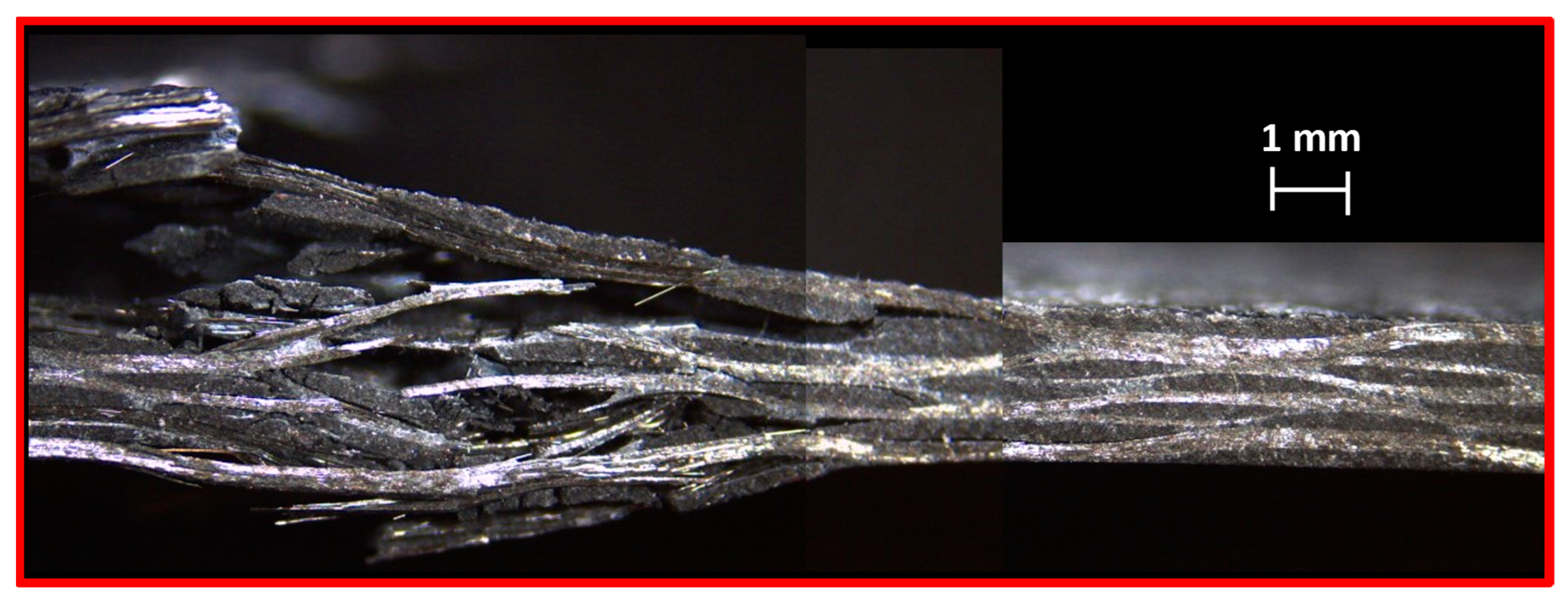
Figure 7 shows the 11× magnification of the fracture zone of a typical specimen in composite laminate manufactured by laying-up plies of 380 g/m
2. In this case, the failure occurred for fracture of the fibers in a central area of the gauge length.
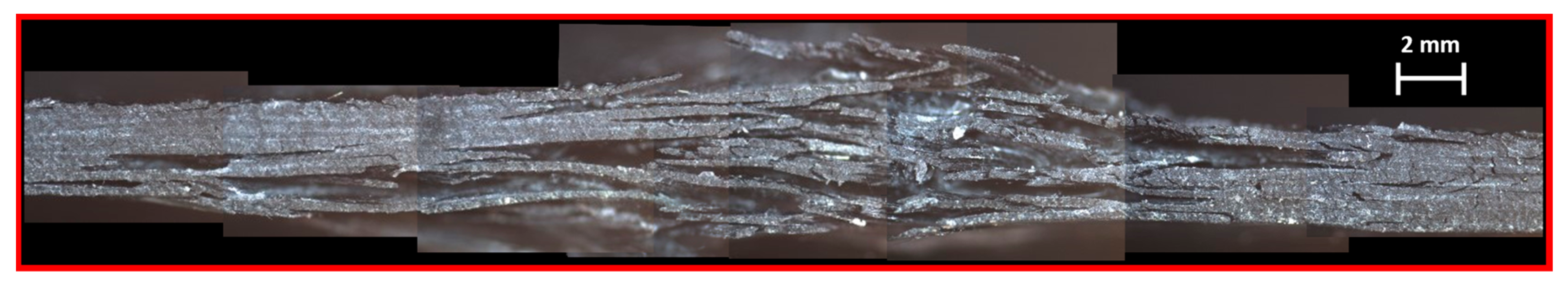
Figure 8 shows the 11× magnification of the fractured longitudinal section of a tensile specimen manufactured at an AW of 630 g/m
2. Unlike the specimen at AW of 380 g/m
2, the failure was caused by delamination, as plies were separated from each other in the perpendicular direction to that of the load application.
Figure 9 shows the fracture zone of a typical specimen in composite laminate manufactured by laying-up plies of 800 g/m
2. The failure mode of such a laminate is different from the one observed in
Figure 8 since delamination is less marked and affects a very small area of the sample. Such behavior can be attributed to the size of the fibers which is equal to 24K for fabric with an AW of 800 g/m
2, whilst is 12K for fabric with an AW of 630 g/m
2. Every fracture mode is in accordance with that reported in ASTM D3039 in the conditions Lateral Gage Middle (LGM) for the 380 g/m
2 fabric and 800 g/m
2, and Delamination Gage Middle (DGM) for the 630 g/m
2 fabric.
Figure 10,
Figure 11 and
Figure 12 show the fractured longitudinal sections of the in-shear specimens in composite laminate manufactured by laying-up plies with AW of 380, 630, and 800 g/m
2, respectively. The specimen at the lowest AW investigated is characterized by a failure that occurs in a rather limited area of the specimen, with not very pronounced delamination (
Figure 10). On the other hand, the specimen with AW of 630 g/m
2 exhibits a wider failure zone, in which delamination is predominant (
Figure 11). The specimen realized with an AW of 800 g/m
2 is characterized by a failure zone with an extensive delamination (
Figure 12). The difference in size for the carbon fiber tows used in specimens with AW of 800 g/m
2 (24K), as compared to the laminates with AW of 380 and 630 g/m
2 (12K), is clearly visible.
Considering the marked delamination between the layers of towpreg observed in the above images, it appears that in some case the weight resin content is not adequate for the amount of reinforcement. This is the case of composite laminate manufactured by laying-up plies of 630 g/m
2 (resin content 32.1%
w/
w). This result can be attributed to the low resin content between the layers, which is inadequate to ensure the adhesion of the layers when the tensile and shear stresses reach values similar to the resistance to failure of the composite laminate. Therefore, a low amount of resin means that the sample failure occurs through a marked debonding of the towpreg layers. Similar considerations can be made for the fabric characterized by an AW of 800 g/m
2. As a matter of fact, even in this case the amount of resin is relatively low (29.7%) and leads to a break very similar to that of the fabric with an AW of 630 g/m
2. Unlike the last one, however, the size of the fibers is 24K instead of 12K, as can also be seen from
Figure 11 and
Figure 12, in which the difference between the thicknesses of the fabrics is quite noticeable. However, when the value of the resin content rises, the debonding is greatly reduced as in the case of composite laminate manufactured by laying-up plies of 380 g/m
2 (resin content 43.9%
w/
w). This also increases the specimens’ interlaminar shear strength. As a result, delamination takes place, and cracks propagate between the interfaces of the layers.
The results obtained from the tensile and in-plane shear stress tests showed that the different fabric AW affects the mechanical performances of the CFRP composite laminate. Such result can be attributed to the different compaction between overlying plies during vacuum bag operations and final autoclave curing process. Specifically, the lowest fabric AW leads to performing a more active compaction and, consequently, to reducing the void content in percentage in the final composite laminate, as also confirmed by the results of the digestion test (
Table 2).
4. Conclusions
The effect of the fabric AW on the mechanical properties of composite laminates in carbon-fiber-reinforced polymers was investigated. Three pre-impregnated 2 × 2 twill weaves, characterized by different AW values of 380 g/m2, 630 g/m2, and 800 g/m2, were used to manufacture composite laminates. They were chosen due to their wide use in the automotive sector for producing structural components by exploiting their high drapability and limited crimping. The final thickness of the laminates was reached by laying-up a different number of plies, i.e., six layers with a fabric AW of 380 g/m2, four layers with an AW of 630 g/m2, and three layers with an AW of 800 g/m2. Uniaxial tensile and in-plane shear response tests were carried out on samples obtained from composite laminates.
Resin digestion tests were carried out to quantify the voids in the composite materials; finally, microscopy and stereomicroscopy analyses were employed to observe the plies and their cross-sections.
The main results can be summarized as follows:
the void content in percentage is higher in the laminates obtained by laying-up fabrics with an AW of 630 g/m2 with respect to those obtained using the weaves with AWs of 380 g/m2 and 800 g/m2;
for a given strain level, a decrease in the fabric AW leads to an increase in strength and stiffness;
the twill waves specimens with the AWs of 380 g/m2 and 800 g/m2 subjected to tensile and in-plane shear tests demonstrate a less evident delamination in a limited failure zone, whilst the twill wave specimens with the AW of 630 g/m2 show a pronounced delamination phenomenon in a wider failure zone;
the twill weave with an AW of 380 g/m2 is characterized by a maximum in-plane shear stress higher than those with an AWs of 630 g/m2 and 800 g/m2; on the contrary, the shear stress chord modulus is higher for the fabric with the AW of 630 g/m2 than for those with AWs of 380 g/m2 and 800 g/m2;
the difference among the mechanical performances of the different AW laminates is related to how the fibers are woven into the different fabrics: as far as the 380 g/m2 fabric is concerned, a pronounced fiber alignment appears, and the bundles of fibers follow almost linear trajectories as compared to the 800 g/m2 fabrics.
These findings can help to better understand composite material behavior by linking their mechanical properties with laminates areal weight. Moreover, they can be employed for an optimal material selection during the design phase, with immediate industrial applications. For example, knowing that laminating a 630 g/m2 AW fabric results in obtaining a higher percentage of voids as compared to 380 g/m2 and 800 g/m2 AW fabrics can affect choices of laminates during the design phase of structural components.
In addition to these results, it is worth to notice that the number of plies has a great influence also on the manufacturing time and costs. This aspect must also be considered by the engineers during the design of CFRP components in order to find the best compromise between mechanical and manufacturing performances.
Further investigations will concern the evaluation of the mechanical performance of laminates realized with different tows (e.g., 3k, 6k, and 12k tows), different weave architectures (e.g., 2 × 2 and 4 × 4 twill), and consequent different AWs, with a particular focus on the fiber bundles analysis, both with optical microscopy and computerized tomography.


