Article

From Nautical Waste to Additive Manufacturing: Sustainable Recycling of High-Density Polyethylene for 3D Printing Applications

1
Department of Industrial Engineering and INSTM Research Unit, University of Trento, Via Sommarive 9, 38123 Trento, Italy
2
Laboratory of Advanced Fibers, Empa, Swiss Federal Laboratories for Materials Science and Technology, Lerchenfeldstrasse 5, 9014 St. Gallen, Switzerland
*
Author to whom correspondence should be addressed.
J. Compos. Sci. 2023, 7(8), 320; https://doi.org/10.3390/jcs7080320
Submission received: 22 June 2023 / Revised: 26 July 2023 / Accepted: 2 August 2023 / Published: 4 August 2023
(This article belongs to the Special Issue Feature Papers in Journal of Composites Science in 2023)

Abstract

:
High-density polyethylene (HDPE) is a highly versatile plastic utilized in various applicative fields such as packaging, agriculture, construction, and consumer goods. Unfortunately, the extensive use of polyethylene has resulted in a substantial accumulation of plastic waste, creating environmental and economic challenges. Consequently, the recycling of polyethylene has become a critical concern in recent times. This work focuses on the recycling of HDPE parts recovered from end-of-life boats into materials suitable for the marine environment with additive manufacturing technology via screw-assisted extrusion 3D printing. In particular, rigid materials are obtained by adding glass fibers to HDPE to mitigate the loss of mechanical performance upon recycling. Eventually, the properties obtained with two different production methods were compared, namely compression molding and screw-assisted extrusion 3D printing. Since the developed materials will be exposed to an aggressive environment, an extended thermos-mechanical characterization (including fatigue resistance) and investigation of the stability to UV exposure were performed.

1. Introduction

Polyethylene (PE) is one of the most widely used plastics in the world, with a wide range of applications, including packaging, agriculture, construction, and consumer goods. However, the widespread use of PE has also led to a significant amount of plastic waste, which poses environmental and economic challenges [1]. Therefore, recycling PE has become a crucial issue in recent years. Recycling is the process of collecting and processing end-of-life materials, which would otherwise be thrown away as garbage, turning them into new products, and then returning them to the stream of use. It represents the most efficient end-of-life scenario for extracting value from the waste stream. The great advantage of the recycling process is linked to the fact that the energy required for this process is generally lower if compared to the embodied energy of the virgin material, thus making recycling an energy-efficient process as it allows to eliminate the energy necessary for the extraction and subsequent processing of the raw materials [2]. Within the recycling market, prices vary based on the balance between supply and demand, the prices of materials obtained from primary resources, as well as the organization and behavior of the markets and related stakeholders [3]. All this makes it difficult to compare the price of the recycled material to that of the primary or virgin material. In general, virgin materials are more expensive than recycled ones because their quality, both in engineering and perceptual terms, is higher. Therefore, an important goal considered by producers using recycled materials is to obtain products with a quality sufficient to be competitive in the market. Specifically, it can be said that by increasing the price of the primary resource, the recycling rate also increases. Despite the fact that plastics represent less than 10% of the weight of all discarded materials, it is perceived by the population as one of the main problems in waste disposal [4]. For this reason, there is a continuing interest in educating people on correct separate collections and, in particular, in improving the image of “plastic” in the minds of the population. Many of the issues raised about polymer recycling are non-technical, including public perception, political maneuvering, and economic incentives [5]. The recycling of plastic waste, when compared with other commonly used materials, such as paper, glass, and metals, has a lower recycling rate. This difference can also be found in those European countries that are very virtuous in recycling [6]. All of this is partly caused by the large number of plastics, additives, and other substances used. On the other hand, this variety represents one of the main advantages of plastic and one of the reasons for its versatility [7].
Additive manufacturing (AM) is defined as a technology capable, starting from a 3D model, of modeling materials layer by layer to obtain objects [8]. The geometry is represented as a series of 2D cross-sections of finite thickness. In general, the term additive manufacturing is also described as synonymous with 3D printing or rapid prototyping. AM processes have assumed great importance in recent decades for many different applications, ranging from aerospace and automotive to biomedical and architectural design. Among the main advantages of this technique is the possibility of obtaining objects even with complex shapes with a limited waste of material [9,10,11]. Among the AM techniques, Fused Filament Fabrication (FFF) has emerged. The ever-growing accomplishment of FFF is due to its benefits over traditional manufacturing methods, such as free design, no need for molds in manufacturing, and the ability to obtain complex parts. Due to its low cost and a large variety of compatible materials, FFF has been widely adopted within research communities, industries, and home users [12]. This is an extrusion-based technique, in which a thermoplastic polymer is supplied as a continuous feed filament into a heated nozzle where its melting occurs. The extruder head performs the function of scanning the horizontal plane as well as starting or stopping the flow of material. After each layer, the deposition bed can move in the vertical axis direction, and the next layer is added until the object is 3D printed. According to Schirmeister et al. [13], the additive manufacturing of HDPE using FFF is problematic owing to its massive shrinkage, voiding, and warpage problems, accompanied by poor adhesion to common build plates and to extruded HDPE strands. Therefore, particular attention must be posed to properly selecting the temperature and the diameter of the nozzle, the extrusion rate, the build plate material, and its temperature. As a solution to warping problems, various research groups have developed melt-processable compounds, such as blends and composites. For instance, Spoerk et al. [14,15,16,17] have published several works on the subject of FFF of propylene/ethylene copolymers and their composites. Their results indicate that the incorporation of spherical fillers, such as glass or perlite microspheres, can help to reduce shrinkage. Additionally, maximizing the interfacial adhesion between the filler and matrix can successfully enhance tensile properties and toughness. Carneiro et al. [18] used FFF to print polypropylene (PP) homopolymer and glass-fiber-filled PP. The study revealed that thermal distortion can be regulated with specific printing conditions. Nevertheless, the printed specimens displayed an up to 30% decrease in mechanical performances compared to compression-molded specimens with the same composition. The pressure of the extruded filament on the previous layer is determined using the mass flow out of the heated nozzle and the viscosity of the molten filament. However, this process imposes significant constraints on the selection of materials, as a high ratio between viscosity and elastic modulus may lead to buckling [19]. Due to this reason, screw-assisted extrusion-based AM has gained importance as an enabling technology to expand the range of 3D printing materials, reducing the costs associated with feedstock fabrication and, therefore, increasing the material deposition rate compared to traditional FFF [20]. The most exploited constructive solution consists of a single-stage process in which a vertical screw extruder extrudes the molten polymer chips directly through the deposition nozzle. For small-scale systems, the printheads often require a miniaturized screw mechanism, and its fabrication may represent most of the development costs [21].
Recycling opportunities in additive manufacturing can help to reduce waste and conserve resources. Some of the key areas where recycling can be applied in additive manufacturing include:
  • Recycling of 3D printing feedstock: The feedstock used in additive manufacturing is typically a plastic or metal filament or powder. These materials can be recycled after use to create new feedstock for 3D printing.
  • Recycling of 3D-printed parts: Three-dimensionally printed parts can be recycled in a number of ways, depending on the material used. For example, plastic 3D-printed parts can be recycled mechanically, while metal parts can be recycled in processes such as smelting or remelting.
  • Recycling of 3D printing support structures: Many 3D-printing processes require the use of support structures to hold up the parts being printed. These structures can often be recycled or reused, reducing waste.
  • Recycling of 3D printing by-products: Additive manufacturing generates a variety of by-products, including dust, scraps, and failed prints. These materials can often be recycled or reused, reducing waste.
AM can contribute to minimizing transportation distance, reducing CO2 emission, eliminating energy consumption caused by transportation, and committing cost saving and shorter lead time. Among all key factors, design flexibility and localization can be the tactical factors enabling AM to fully utilize the collection–recycling–manufacturing model and augment the advantages of AM [22]. Pearce et al. conducted a life cycle analysis that suggests that utilizing an open-source plastic extruder to produce filament from HDPE waste and subsequently using it for 3D printing value-added parts could be beneficial in terms of distributed recycling [23]. To facilitate this process, they developed a recycling unit called RecycleBot, which can melt plastic waste, such as shredded milk jugs and transform them into filaments for FFF printing. Chong et al. have successfully exhibited the practicality of extruding filaments from HDPE waste material with the intention of using recycled HDPE for 3D printing. Nonetheless, they have highlighted issues related to adhesion and warpage in 3D printing and have examined previous efforts that were unable to address these concerns [24]. Recycling opportunities in additive manufacturing can help to reduce waste and conserve resources. By implementing recycling strategies in the 3D-printing process, we can create a more sustainable manufacturing industry.
Initially, a characterization of the processability and mechanical properties of high-density polyethylene was performed to establish its properties profile. In particular, the properties of the virgin material were compared with those of the material recovered at the end of life from roto-molded boat hulls. Composites with recycled material and fiberglass were developed to try to limit the degradation of mechanical properties. However, in contrast to traditional design processes, we then considered higher-value system-specific opportunities for reuse (upcycling) in the field of AM. To demonstrate this, specimens containing recycled HDPE and glass fibers were printed with the aid of a screw-assisted extrusion 3D printer, and the final properties were compared to the ones obtained from compression molded material.

2. Materials and Methods

2.1. Materials

Virgin HDPE was provided by Gerbaldo Polimeri SpA (Cuneo, Italy) with the tradename Hexell AG335. End-of-life (EL) HDPE components were provided by GardaSolar: they consist of aesthetic parts located in the upper part of a boat made with the HDPE Hexell AG335 using a roto-molding technique and discharged after 3 years of outdoor service (Figure 1). EL parts were granulated into chips using a mechanical grinder (Piovan RN 1515). E-glass fibers, designed as 248AF, were supplied by Owens Corning (Toledo, OH, USA) in form of chopped strands produced by assembling sized Advantex E-Glass continuous fibers with a nominal diameter of 13 μm and cutting them to lengths between 4.0 and 4.5 mm. To improve the adhesion between PE and GF, a compatibilizer, Compoline CO/LL 05, was supplied by Auserpolimeri (Lucca, Italy). It consists of a linear low-density polyethylene blend modified with maleic anhydride. Recommended dosage level of Compoline® CO/LL 05 is about 3–5%, and the shelf life is 2 years.

2.2. Sample Preparation

All materials were dried at least 2 h at 80 °C under vacuum before processing. Homogeneous mixtures were produced with the aid of a Thermo-Haake Polylab Rheomix counter-rotating internal mixer at 160 °C, rotor speed 60 rpm for 10 min until a constant torque was reached. Melt compounded materials, upon granulation, were hot pressed in a Carver Laboratory press at a temperature of 160 °C, under a pressure of 7 MPa, applied for 10 min, and then water cooled to room temperature to obtain square plates with dimensions 120 × 120 × 2 mm.
Three-dimensionally printed specimens were manufactured via material extrusion with a screw extruder provided by Direct3D printer (Milano, Italy) (Figure 2). The temperature of the nozzle was set at 230 °C, while the bed temperature was set at 90 °C. The nozzle had a diameter of 1 mm, the layer height was 0.5 mm, and the deposition was conducted at a speed of 20 mm s−1. Dumbbell-shaped specimens were built-up along with the horizontal directions with 100% density. The raster angle, which refers to the angle between the path of the nozzle and the X-axis of the printing platform during 3DP, was set to an angle of ±45°.
The notation for the samples in this work was identified, indicating the matrix type, the filler, the compatibilizer, and the manufacturing technique. For example, a sample of “40VM-60EL/15GF/5MA CM” indicates 40 wt% of virgin HDPE Hexell AG335 and 60 wt% of recycled end-of-life material filled with 15 wt% of glass fibers and 5%wt of PE-g-MA obtained via compression molding (CM).

2.3. Characterization Techniques

Thermogravimetric analysis (TGA) tests were performed using a Mettler TG 50 thermobalance in the range of 30–700 °C at a heating rate of 10 °C/min under a continuous air flow with a rate of 100 mL/min. From TGA analysis, the evaluation of the temperature associated with mass losses at 5% (T5%) and 10% (T10%), and decomposition temperature (Td), referred to as the maximum degradation rate of the first derivative (DTG) diagram, were determined.
Differential Scanning Calorimetry (DSC) analysis was performed with a Mettler DSC30 calorimeter in a temperature range from 0 °C to 200 °C with a heating and cooling temperature of 10 °C/min. The analysis was carried out in a controlled atmosphere constituted with nitrogen flow of 100 mL/min. The crystallinity content (𝜒) of the composite blends was calculated considering a theoretical enthalpy of 100% crystalline polyethylene of 293 J/g [25].
Melt Flow Index (MFI) measurements were carried out using a Dynisco 4002 device at 190 °C under an applied load of 2.16 kg.
Morphology of the fracture surfaces was studied using a Carl Zeiss AG Supra 40 field emission scanning electron microscope (FESEM). Specimens were broken in liquid nitrogen, and the fracture surfaces were observed at an acceleration voltage of 4 kV. Representative micrographs at different levels of magnification were selected.
Quasi-static uniaxial tensile tests were performed at room temperature using an Instron 5969 electromechanical testing machine equipped with a 50 kN load cell. For the measurement of the elastic modulus, at least five specimens were tested for each composition at 0.25 mm/min, with a resistance extensometer Instron 2620 having a gauge length of 12.5 mm. The modulus of elasticity was calculated according to ISO 527. Tensile properties until fracture were measured at a crosshead speed of 100 mm/min.
Accelerated ultraviolet exposure (UV testing) was performed to understand how a material will withstand the damaging effects of ultraviolet exposure, which can cause significant degradation of the properties and useful life of a material. To simulate the weathering effect, accelerated ultraviolet exposure (UV testing) was performed using UV-B cyclic exposure tests with a wavelength peak of 313 nm. The tests were performed directly on ISO 527 1BA specimens with exposure times of 7 and 14 days.
Fourier-transform infrared (FTIR) spectra were recorded using a Spectrum OneTM spectrometer (Perkin Elmer ATR-FTIR, USA) in a scanning range from 4000 cm−1 to 650 cm−1 and a resolution of 4 cm−1. Four scans for each specimen were recorded.
The Vicat Softening Temperature was measured using a Microprocessor HDT-Vicat tester model MP/3. The test consisted of the application of a load (of 10 and 50 N) on a needle with cylindrical flat tip of area 1 mm2 pressing on a sample immersed in a thermally controlled oil bath with temperature that increased at a rate of 120 °C/h, starting from room temperature. The Vicat softening temperature was determined when the needle penetration reached 1 mm.
Fatigue tests were performed at room temperature under tension–tension sinusoidal load control using a closed loop servo hydraulic MTS 858 Mini Bionix testing machine equipped with a load cell of 25 kN. The minimum to maximum stress ratio (R = σmaxmin) was kept equal to 0.1, and the cycle load frequency was 2 Hz. This frequency was chosen to avoid excessive heating of the specimens [26,27]. The free length between grips was fixed at 30 mm. Tests exceeding 106 cycles were stopped even if the fatigue fracture was not reached. During the fatigue experiments, signals from the load cell and the LVDT channels were periodically recorded, and the number of cycles was registered. The number of cycles to fracture (Nf) or fatigue life was obtained on at least three repeated tests conducted for each stress amplitude.

3. Results

3.1. Evaluation of Recovered HDPE

In the first part of the work, both virgin and end-of-life polyethylenes have been characterized in order to gain information on the degradation state of the latter one. Thermogravimetric curves of virgin Hexell AG355 named 100VM and end-of-life recovered material, 100EL, along with the corresponding derivative curves, are presented in Figure 3a. A difference in degradation behavior as a function of temperature can be seen for virgin and end-of-life materials. Specifically, it is noted that in the case of end-of-life material, the degradation process begins at 365 °C, i.e., a much lower temperature in comparison to the 422 °C of the virgin material. Moreover, after the aging of the material, the thermal degradation curve changed completely from a sharp to a smoother weight loss trend. A sharp drop can occur due to the formation of a protective layer on the surface of the material or due to the exhaustion of a volatile component that could be consumed by evaporation during the life of the material resulting in a continuous reaction of thermal degradation, rather than a sudden, drastic change in the rate of degradation. Therefore, it should be considered that any thermal process carried out on the material causes an increase in its degradation level. The degradative process also affects the crystallinity content of the material. In Figure 3b, DSC curves for virgin and end-of-life materials are shown. Generally, the degradation of polymers to form smaller molecules can occur by specific or random scission. Specifically, in the case of HDPE, degradation occurs by random scission, that is, via the random breaking of the bonds inside the polymer [28]. Due to this degradative process, the molecules are shortened. Therefore, the material is able to crystallize better. In fact, the degree of crystallinity (measured in the second DSC scan) reaches 54% for the EL polyethylene, while the virgin material is limited to 48%. This shortening of the length of the molecules due to the degradation of the material during aging causes a reduction in the material’s viscosity. It was evident that in the case of end-of-life materials, the MFI increases considerably, reaching a value of 6.32 ± 0.10 g/10 min, while the MFI value of the virgin material is 3.61 ± 0.08 g/10 min.

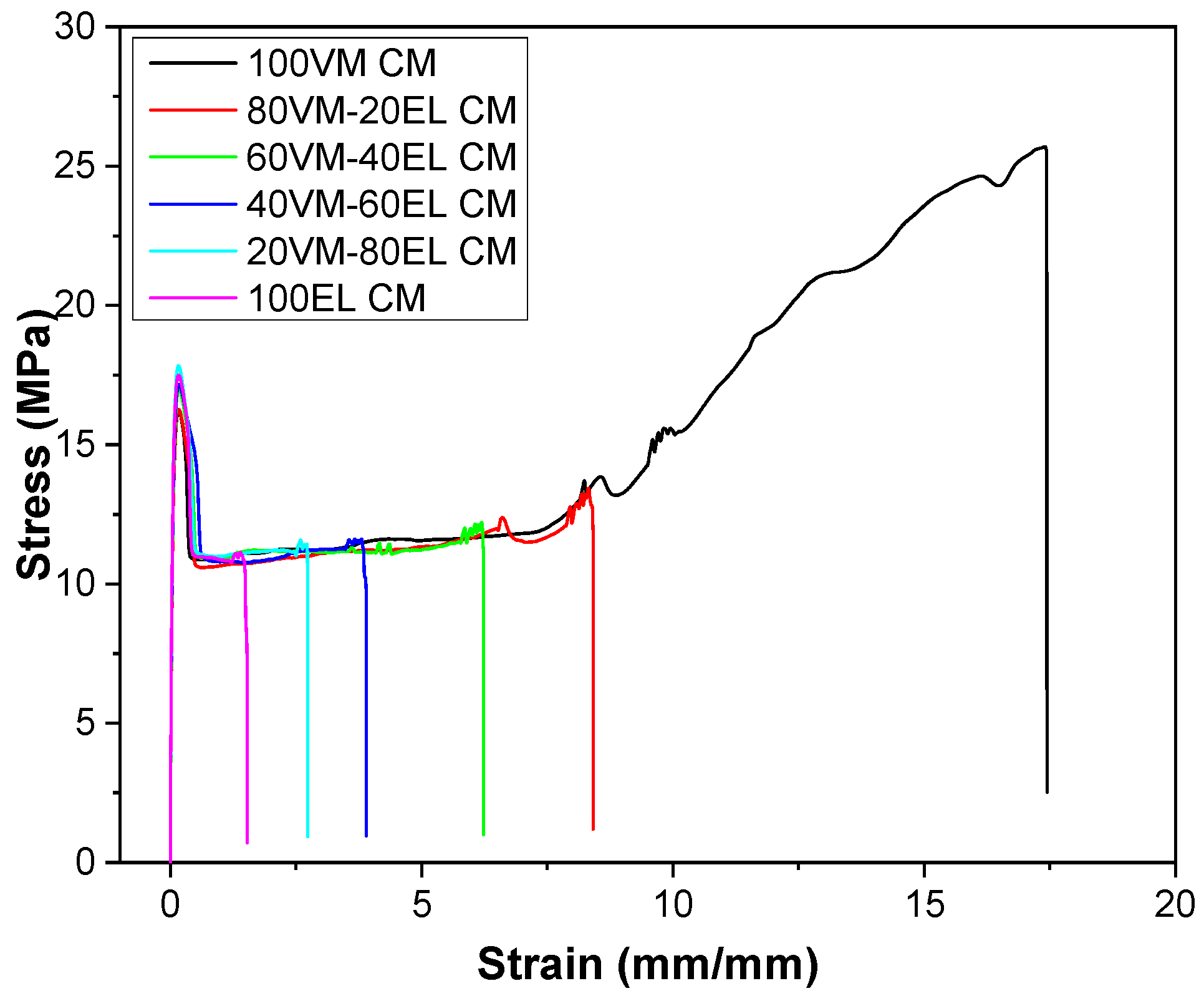
3.2. Recycled HDPE Blends

In order to produce a blend containing the largest possible amount of recycled HDPE, various increasing amounts of end-of-life material were mixed with virgin material. In this way, it was possible to characterize the effects of the amount of recycled material on various properties with a special focus on the mechanical response. Representative stress–strain curves of HDPE blends are shown in Figure 4, and the results of the quasi-static tensile tests are resumed in Table 1. It can be observed that the elastic modulus of the materials containing recycled polyethylene remained practically constant. At the same time, a reduction in the ultimate properties (σb and εb) can be noticed across all the investigated compositions. This phenomenon could be likely due to the presence of impurities and structural defects introduced during the recycling process, which can weaken the material and make it more prone to failure under stress. This decrease in the ultimate properties of the material can be mitigated with the introduction of glass fibers into the recycled material composition. The glass fibers provide additional strength and reinforce the material, which can help to counteract the negative effects introduced by recycled material. In the next section, the activities to optimize the amount and orientation of glass fibers to achieve the best balance between strength and other desired properties will be presented.

3.3. Glass Fibers and Compatibilizer Effect

Fiber dispersion and fiber–matrix adhesion play important roles in determining the mechanical properties of HDPE composites. Under tensile mode, loads cannot be directly applied to the fibers but transferred from the matrix to the fibers through the interface. This requires a good interaction between the fiber and the matrix, which can then be controlled via the surface treatment of the fibers or coupling agents. This paragraph focuses on the characterization of composite materials based on glass fibers, to which grafted coupling agent (polyethylene grafted maleic anhydride PE-g-MA) is introduced in order to improve the mechanical properties of the composites. The SEM micrographs reported in Figure 5 allow us to investigate the morphology of the obtained composite materials. In particular, from Figure 5a,b, details of the surface of the glass fibers in the absence or in the presence of the compatibilizer can be highlighted. Specifically, it is observed that in the absence of PE-g-MA, the surface appears much smoother and regular. At lower magnification (Figure 5c,d), it can be observed that the fibers without compatibilizer seem to be more easily debonded from the matrix, and the protruded fiber lengths are longer. Therefore, in the case of the addition of the compatibilizer, an improvement in the fiber-matrix adhesion can be hypothesized. Finally, comparing the micrographs of Figure 5e,f, referring to the composite material with 15% of glass fibers and 2% and 10% of PE-g-MA, no remarkable differences can be observed.
Thermogravimetric analysis results for HDPE virgin material compounded with GF and an increasing amount of MA are summarized in Table 2. The resistance to degradation, as evidenced by the T5%, T10%, and Td values, decreases with an increase in the amount of maleic anhydride. This suggests that the material’s thermal stability (and, therefore, the outdoor durability) is negatively impacted by the presence of this additive [29].
Some important considerations can be extrapolated from the quasi-static tensile test on virgin HDPE material compounded with different amounts of glass fibers and compatibilizers. The obtained parameters are graphically presented in Figure 6 and summarized in Table 3. Firstly, the elastic modulus is not influenced by the PE-g-MA content, while the glass fibers play a fundamental role in improving the elastic modulus. Glass fibers are known to be strong and stiff, and their presence in the HDPE blend likely increases the inter-fiber bonding, resulting in a stronger and stiffer composite material. This is reflected in the higher elastic modulus value. Moreover, it has been observed that the yield strength of a composite material filled with glass fibers and a small amount of polyethylene grafted with maleic anhydride (PE-g-MA) as a compatibilizer increases significantly, reaching a maximum value for compatibilizer contents between 2 and 5%. This suggests that the addition of the compatibilizer improves the mechanical properties of the composite material. The improved yield strength is likely due to the higher interfacial compatibility between the glass fibers and the HDPE matrix, resulting in a better load transfer at the fiber-matrix interface. However, for higher compatibilizer contents, it has been observed that the advantage derived from its use is practically lost, meaning that the improvement in mechanical properties is no longer observed. This finding is in line with the technical datasheet, which recommends a PE-g-MA dosage level of 3–5%. In the case of a composite material filled with glass fibers and a small amount of polyethylene grafted with maleic anhydride (PE-g-MA) as a compatibilizer, it has been observed that the elongation at break decreases significantly with the addition of a small amount of compatibilizer. The decrease in elongation at break from 192% to 20% with an addition of just 2% of PE-g-MA suggests that the presence of the compatibilizer is causing the material to become more brittle and less able to deform before breaking. This behavior can be explained by the role of the compatibilizer, which is to improve the compatibility between the glass fibers and the HDPE matrix, resulting in better inter-fiber bonding and a stronger composite material [30,31]. However, this increased strength also means that the material is less able to deform before breaking, as the bonds between the fibers and the matrix are stronger and less capable of deformation. At higher compatibilizer contents, it has been observed that the elongation at break reaches a plateau, meaning that the material’s behavior becomes more stable and less influenced by the addition of the compatibilizer.

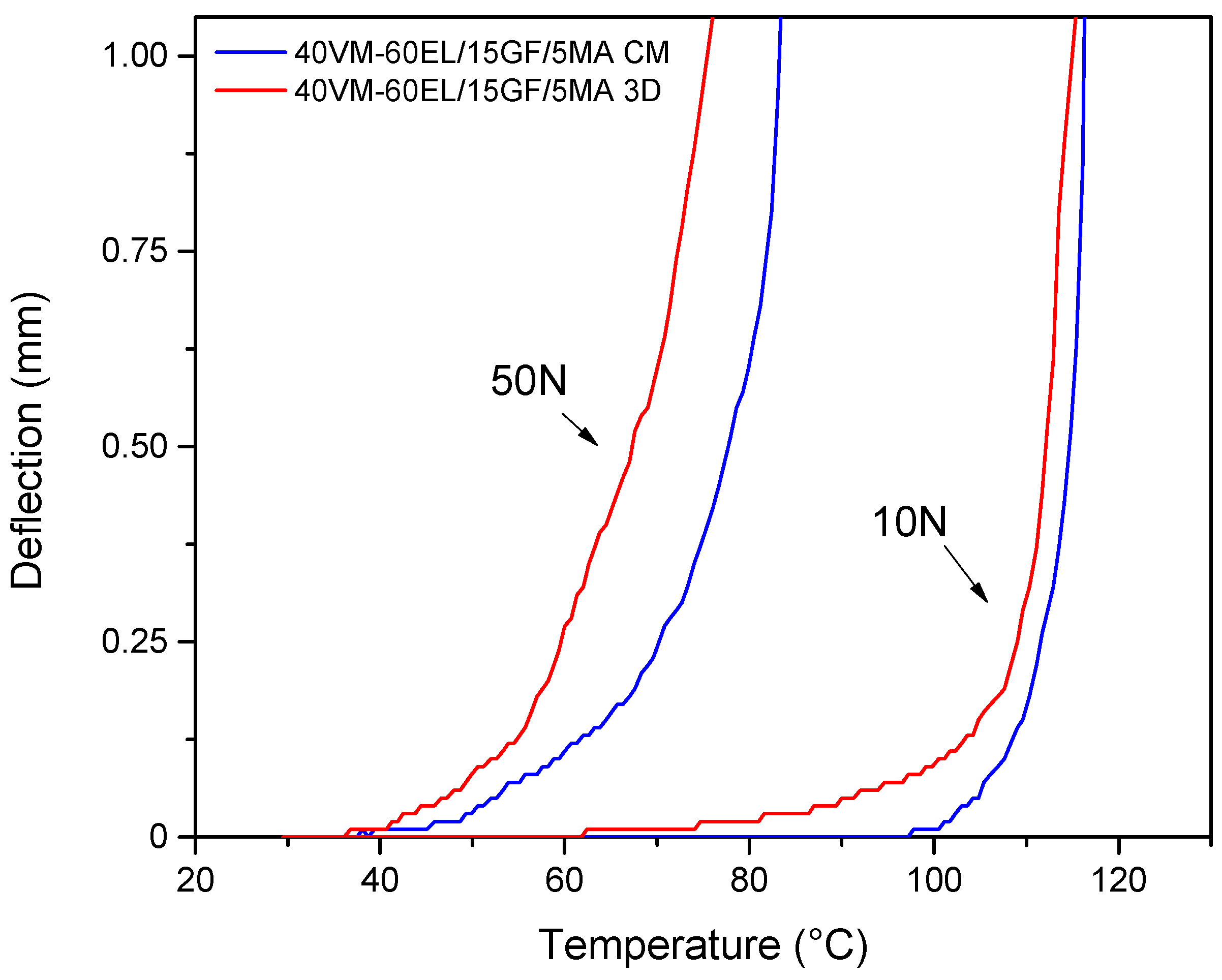
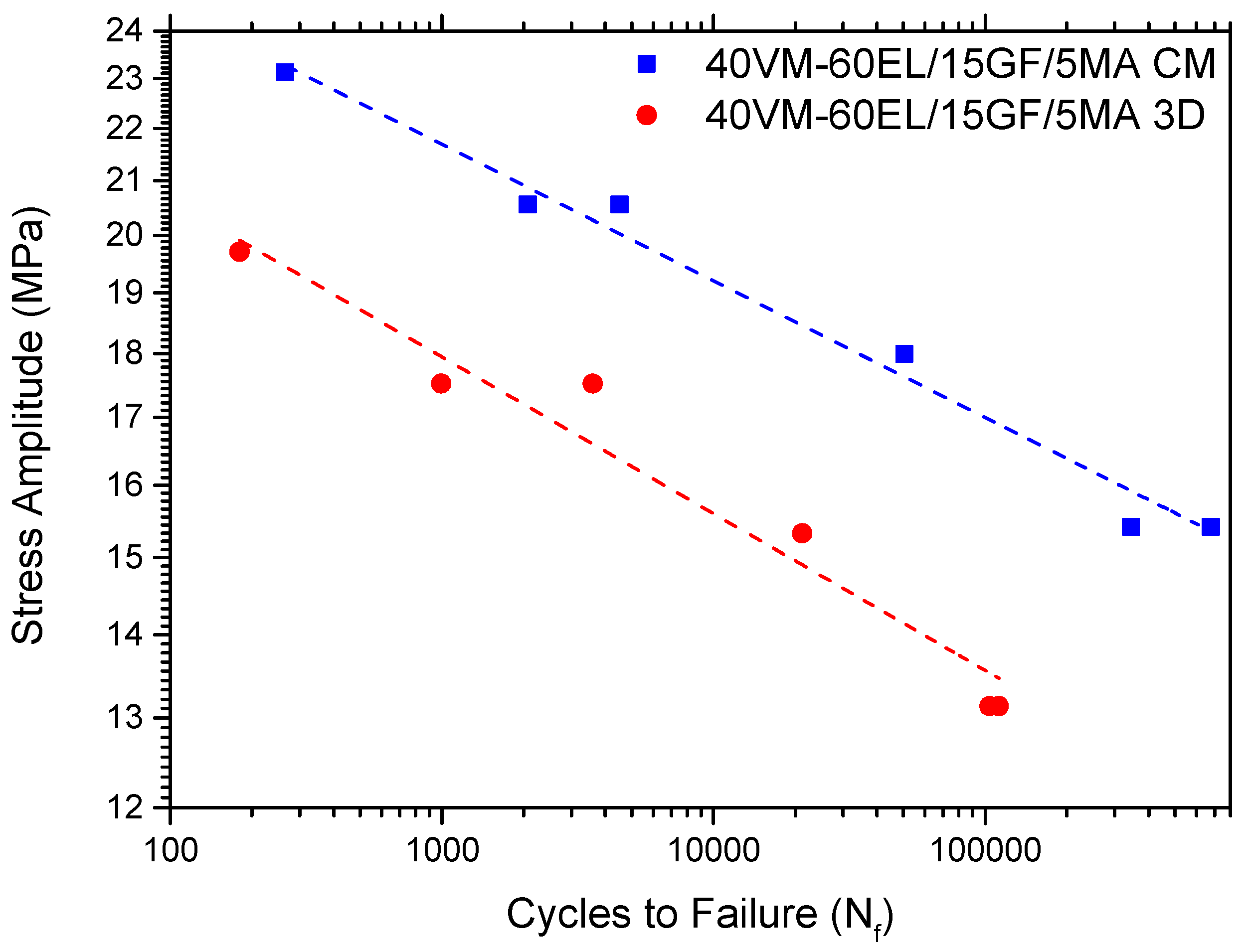
3.4. Three-Dimensionally Printed Material

In the last part of this work, the characterization of the 3D-printed final rigid composite material is carried out. In particular, from the obtained properties presented in the previous chapter, the compositions consisting of 40% virgin material, 60% recycled material, 15% GF, and 5% MA were selected, as they allow us to obtain a good combination of the quantity of recycled material used and the mechanical properties obtained. This composition was subsequently printed using a 3D pellets printer.
Based on the micrographs presented above in Figure 7, it can be observed that specimens obtained via 3D printing display a degree of surface irregularity that is closely linked to the flow of the printing material and the sequence of the layer deposition process. Additionally, the presence of defects, imperfections, and extended porosities within the material can also be identified. This is likely due to the layer-by-layer process of 3D printing, which can introduce inconsistencies and variations in the material as it is being printed. It is important to consider these observations when evaluating the mechanical properties of 3D printed specimens, as these defects and imperfections can significantly impact the material’s overall strength and durability.
The comparison of the quasi-static tensile tests for the same composites obtained by compression molding and 3D printing is presented in Table 4. It has been observed that the elastic modulus is higher for 3D-printed specimens compared to the ones obtained from compression molding. This behavior can be explained by the different microstructures of the two manufacturing methods. In compression molding, the polymer is heated until it melts and is then pressed between two plates, causing it to solidify and take on the shape of the mold. During this process, the polymer chains can become disordered and tangled, resulting in a less organized and less crystalline structure. This can lead to a lower elastic modulus, as the disordered structure is less able to resist deformation. In contrast, 3D printing involves the layer-by-layer deposition of the polymer, which can result in a more ordered and crystalline structure. The printing process can allow for better control of the orientation of the polymer chains and the reinforcing fibers, resulting in a more aligned and organized structure. This can lead to higher elastic modulus values, as the aligned and ordered structure is less deformable. It is important to note that the crystallinity fraction of CM and 3D printed material is the same according to DSC analysis and equal to 55%. In general, it is possible to observe that the properties achievable via 3D printing are slightly lower when compared to those achieved via compression molding. This difference is most evident in the maximum load that the composite material can withstand, while the difference is less significant when comparing elongation at break values. This behavior may be explained by the additional step required to obtain 3D printed specimens, in which the material is granulated into suitable pellets to feed the printer hopper. Each additional step in the process can cause a degradation of the material, which may have a negative impact on the final achievable properties. When considering 3D printing, it is important to take into account a geometric effect related to how the specimen is constructed. This effect can result in the presence of defects, porosity, or imperfections within the material. In other words, the layer-by-layer nature of 3D printing can introduce inconsistencies in the material, which can impact the mechanical properties. This is especially important when considering the quality of the final product, as defects or porosity within the material can compromise its overall strength and durability. Therefore, it is crucial to carefully evaluate the quality of the 3D-printed specimens, taking into account the potential presence of these geometric effects.
Since the final material is designed for nautical applications, UV exposure tests have been also carried out. After being exposed for 7 and 14 days to UV, the mechanical properties of the material were measured, and the results are presented in Table 4. It can be observed that as the exposure time increases, the elastic modulus of the material decreases. Additionally, there is a slight decrease in both the tensile strength and elongation at break. These findings suggest that the material’s mechanical properties are adversely affected by prolonged exposure to external factors, which can lead to reduced performance and a shorter lifespan.
Exposure of a material to UV radiation can lead to various photochemical reactions, altering the material’s molecular structure [32]. In fact, the high energy photons in UV light can induce the formation of crosslinked structures or photo-oxidation-induced chain scissions [33]. For instance, in polymers such as polyethylene, the formation of crosslinks due to UV exposure can enhance the material’s stiffness, resulting in an embrittlement over time [34] and a reduced fatigue life [35]. The FTIR analysis performed on the 3D printed specimens (Figure 8) revealed that with an increase in exposure time, there was a corresponding increase in the peak at around 3300 cm−1, which corresponds to the stretching vibration of hydrogen-bonded hydroxyl groups in the polymeric association. This could indicate an increase in the oxidation of the material, which can result in increased brittleness and greater susceptibility to cracking [33]. An increase in the peak associated with the C=O bond at 1740 cm−1 and the peak at 1597 cm−1, which may be associated with the vibration of the CH2 in the CH2OH group, is also observed. This provides further evidence of oxidation occurring and chemical degradation.
Figure 9 shows the results of Vicat Softening Temperature (VST) tests performed on various composite materials, while the relative values are reported in Table 5. The tests were conducted under two different load conditions, 10 N and 50 N, as per ASTM D1525 standards, to study the material behavior under varying load conditions. When comparing the VST values of the composite materials produced by compression molding and 3D printing, it can be observed that the VST value for the 3D-printed material is slightly lower. The lower Vicat Softening Temperature (VST) observed in 3D-printed objects compared to compression molded materials is likely due to the presence of defects and porosity within the 3D-printed material. The process of 3D printing involves melting the material and then depositing it layer by layer, which can result in the formation of voids or air pockets within the material. These voids and air pockets can act as stress concentrators and reduce the overall strength of the material. In addition, the porosity can also reduce the density of the material, which can affect its thermal properties, including the Vicat Softening Temperature. Therefore, due to the presence of these defects and porosity, 3D-printed objects may display a lower Vicat Softening Temperature compared to materials that have been compression molded without these issues.
The fatigue life performances of compression molded and 3D-printed 40VM-60EL/15GF/5MA blends were obtained using uniaxial fatigue tests. The obtained stress amplitude (σa) -number of cycles to failure (Nf) curves are given in Figure 10. When a material is subjected to cyclic loading, it can experience fatigue failure if the stress level exceeds a certain threshold. The number of cycles that a material can withstand before it fails is known as its fatigue life, and this property is of utmost importance in many engineering applications. By plotting the fatigue data on a double logarithmic scale, a linear relationship between the cyclic stress and the number of cycles to failure can be established.
To understand the effect of the manufacturing technique on the fatigue performance of HDPE polymer blends, the following Basquin equation was used [36,37,38]. The stress amplitude versus the number of cycles to failure data were fitted to σ-N curves.
σ = Sf (Nf)a
where σ is the fatigue stress level, Nf is the number of cycles to fracture at σ, Sf is the fatigue strength coefficient, and a is the fatigue strength exponent. Therefore, fitting a straight line to the fatigue data represented on a double logarithmic scale obtains the Basquin equation’s coefficients (Sf and a). The obtained values are summarized in Table 6. It is possible to observe a good linear relation highlighted by an adjusted R2 near 1. In addition, it is worth noting that the fatigue properties of the composite material obtained by 3D printing are significantly lower than those of the same material obtained by compression molding [39]. The difference in fatigue behavior is mainly attributed to the internal defects and imperfections present in the 3D-printed specimens, which have a considerable influence on the final fatigue properties of the material [40,41,42]. Basquin’s equation can be used to predict the maximum cyclic load that a material can withstand without experiencing fatigue failure, and this information is crucial for designing reliable and durable structures in various engineering applications.

4. Conclusions

In this article, a 3D-printable material based on recycled HDPE suitable for the marine environment has been developed and characterized. In particular, after the assessment of the mechanical and physical characteristics of the received starting material, various amounts of virgin and recycled polyethylene were mixed in order to obtain a matrix that could subsequently be reinforced with glass fibers, and by using a compatibilizer, the fiber–matrix adhesion properties have been optimized. Due to the degradation of the recycled material, the molecules are shortened; therefore, the reprocessed material showed an increase in crystallinity and a decrease in mechanical properties. This decrement was mitigated by the addition of glass fibers for the development of composite materials, allowing for a considerable increase in the elastic modulus. Specifically, a content of between 10 and 15% of glass fibers was found to be sufficient to cause a doubling of the elastic modulus value and, therefore, a stiffening of the material. However, a small amount of glass fibers introduced into the composite material is enough to cause the elongation at break to decay brutally because there is an increase in the brittleness of the composite material, which gradually tends to behave more and more as a brittle material rather than a ductile one. Finally, lower properties are observed in the case of specimens obtained by 3D printing than those possessed by specimens obtained by compression molding. Specifically, in the case of the specimens obtained by 3D printing, there is a decrease in mechanical properties due to the presence of defects intrinsic to the technology of 3D printing and the presence of voids inside the material. In conclusion, this work made it possible to develop a 3D-printable composite material that presented a good combination of the required properties and the amount of recycled material used up to 60% and suggested the possible upcycle of this material in marine applications.

Author Contributions

Conceptualization, S.D. and P.A.; methodology, S.D. and P.A.; software, R.D.; validation, S.D., D.A. and R.D.; formal analysis, R.D.; investigation, D.A.; resources, S.D.; data curation, R.D.; writing—original draft preparation, R.D., D.A. and S.D.; writing—review and editing, R.D. and P.A.; supervision, P.A.; project administration, P.A.; funding acquisition, P.A. All authors have read and agreed to the published version of the manuscript.

Funding

This research received no external funding.

Data Availability Statement

The data that support the findings of this study are available from the corresponding author upon reasonable request.

Acknowledgments

These research activities have been conducted in collaboration with GardaSolar s.r.l. (Rovereto, Italy) and sponsored by the Provincia Autonoma di Trento (PAT) through Legge 6/99, project “Differenziale meccatronico per la pedalata assistita di natanti con varo/alaggio autonomo mediante ruota idrodinamica”.

Conflicts of Interest

The authors declare no conflict of interest.

References

  1. Zhao, X.; Korey, M.; Li, K.; Copenhaver, K.; Tekinalp, H.; Celik, S.; Kalaitzidou, K.; Ruan, R.; Ragauskas, A.J.; Ozcan, S. Plastic waste upcycling toward a circular economy. Chem. Eng. J. 2022, 428, 131928. [Google Scholar] [CrossRef]
  2. Rabin Tuladhar, S.Y. Use of Recycled Plastics in Eco-efficient Concrete. In Sustainability of Using Recycled Plastic Fiber in Concrete; Woodhead Publishing: Cambridge, UK, 2019. [Google Scholar]
  3. Keilhacker, M.L.; Minner, S. Supply chain risk management for critical commodities: A system dynamics model for the case of the rare earth elements. Resour. Conserv. Recycl. 2017, 125, 349–362. [Google Scholar] [CrossRef]
  4. Luttenberger, L.R. Waste management challenges in transition to circular economy—Case of Croatia. J. Clean. Prod. 2020, 256, 120495. [Google Scholar] [CrossRef]
  5. Maris, J.; Bourdon, S.; Brossard, J.-M.; Cauret, L.; Fontaine, L.; Montembault, V. Mechanical recycling: Compatibilization of mixed thermoplastic wastes. Polym. Degrad. Stab. 2018, 147, 245–266. [Google Scholar] [CrossRef]
  6. Matthews, C.; Moran, F.; Jaiswal, A.K. A review on European Union’s strategy for plastics in a circular economy and its impact on food safety. J. Clean. Prod. 2021, 283, 125263. [Google Scholar] [CrossRef]
  7. Bishop, G.; Styles, D.; Lens, P.N.L. Recycling of European plastic is a pathway for plastic debris in the ocean. Environ. Int. 2020, 142, 105893. [Google Scholar] [CrossRef] [PubMed]
  8. Rigotti, D.; Pegoretti, A. 23—Additive manufacturing with biodegradable polymers. In Biodegradable Polymers, Blends and Composites; Mavinkere Rangappa, S., Parameswaranpillai, J., Siengchin, S., Ramesh, M., Eds.; Woodhead Publishing: Cambridge, UK, 2022; pp. 611–679. [Google Scholar]
  9. Krawczak, P. Additive manufacturing of plastic and polymer composite parts: Promises and challenges of 3D-printing. eXPRESS Polym. Lett. 2015, 9, 959. [Google Scholar] [CrossRef]
  10. Cruz Sanchez, F.A.; Boudaoud, H.; Camargo, M.; Pearce, J.M. Plastic recycling in additive manufacturing: A systematic literature review and opportunities for the circular economy. J. Clean. Prod. 2020, 264, 121602. [Google Scholar] [CrossRef]
  11. Sathies, T.; Senthil, P.; Anoop, M.S. A review on advancements in applications of fused deposition modelling process. Rapid Prototyp. J. 2020, 26, 669–687. [Google Scholar] [CrossRef]
  12. Cataldi, A.; Rigotti, D.; Nguyen, V.D.H.; Pegoretti, A. Polyvinyl alcohol reinforced with crystalline nanocellulose for 3D printing application. Mater. Today Commun. 2018, 15, 236–244. [Google Scholar] [CrossRef]
  13. Schirmeister, C.G.; Hees, T.; Licht, E.H.; Mülhaupt, R. 3D printing of high density polyethylene by fused filament fabrication. Addit. Manuf. 2019, 28, 152–159. [Google Scholar] [CrossRef]
  14. Spoerk, M.; Arbeiter, F.; Raguž, I.; Weingrill, G.; Fischinger, T.; Traxler, G.; Schuschnigg, S.; Cardon, L.; Holzer, C. Polypropylene Filled With Glass Spheres in Extrusion-Based Additive Manufacturing: Effect of Filler Size and Printing Chamber Temperature. Macromol. Mater. Eng. 2018, 303, 1800179. [Google Scholar] [CrossRef]
  15. Spoerk, M.; Gonzalez-Gutierrez, J.; Lichal, C.; Cajner, H.; Berger, G.R.; Schuschnigg, S.; Cardon, L.; Holzer, C. Optimisation of the Adhesion of Polypropylene-Based Materials during Extrusion-Based Additive Manufacturing. Polymers 2018, 10, 490. [Google Scholar] [CrossRef] [PubMed] [Green Version]
  16. Spoerk, M.; Sapkota, J.; Weingrill, G.; Fischinger, T.; Arbeiter, F.; Holzer, C. Shrinkage and Warpage Optimization of Expanded-Perlite-Filled Polypropylene Composites in Extrusion-Based Additive Manufacturing. Macromol. Mater. Eng. 2017, 302, 1700143. [Google Scholar] [CrossRef]
  17. Spoerk, M.; Savandaiah, C.; Arbeiter, F.; Sapkota, J.; Holzer, C. Optimization of mechanical properties of glass-spheres-filled polypropylene composites for extrusion-based additive manufacturing. Polym. Compos. 2019, 40, 638–651. [Google Scholar] [CrossRef]
  18. Carneiro, O.S.; Silva, A.F.; Gomes, R. Fused deposition modeling with polypropylene. Mater. Des. 2015, 83, 768–776. [Google Scholar] [CrossRef]
  19. Singh, S.; Ramakrishna, S.; Singh, R. Material issues in additive manufacturing: A review. J. Manuf. Process. 2017, 25, 185–200. [Google Scholar] [CrossRef]
  20. Barera, G.; Dul, S.; Pegoretti, A. Screw Extrusion Additive Manufacturing of Carbon Fiber Reinforced PA6 Tools. J. Mater. Eng. Perform. 2023. [Google Scholar] [CrossRef]
  21. Justino Netto, J.M.; Idogava, H.T.; Frezzatto Santos, L.E.; Silveira, Z.d.C.; Romio, P.; Alves, J.L. Screw-assisted 3D printing with granulated materials: A systematic review. Int. J. Adv. Manuf. Technol. 2021, 115, 2711–2727. [Google Scholar] [CrossRef]
  22. Wu, H.; Mehrabi, H.; Karagiannidis, P.; Naveed, N. Additive manufacturing of recycled plastics: Strategies towards a more sustainable future. J. Clean. Prod. 2022, 335, 130236. [Google Scholar] [CrossRef]
  23. Kreiger, M.A.; Mulder, M.L.; Glover, A.G.; Pearce, J.M. Life cycle analysis of distributed recycling of post-consumer high density polyethylene for 3-D printing filament. J. Clean. Prod. 2014, 70, 90–96. [Google Scholar] [CrossRef] [Green Version]
  24. Chong, S.; Pan, G.-T.; Khalid, M.; Yang, T.C.K.; Hung, S.-T.; Huang, C.-M. Physical Characterization and Pre-assessment of Recycled High-Density Polyethylene as 3D Printing Material. J. Polym. Environ. 2017, 25, 136–145. [Google Scholar] [CrossRef]
  25. Brandrup, J.; Immergut, E.H.; Grulke, E.A.; Abe, A.; Bloch, D.R. Polymer handbook; Wiley: New York, NY, USA, 1999; Volume 89. [Google Scholar]
  26. Berrehili, A.; Castagnet, S.; Nadot, Y. Multiaxial fatigue criterion for a high-density polyethylene thermoplastic. Fatigue Fract. Eng. Mater. Struct. 2010, 33, 345–357. [Google Scholar] [CrossRef]
  27. Kazanci, M.; Cohn, D.; Marom, G.; Migliaresi, C.; Pegoretti, A. Fatigue characterization of polyethylene fiber reinforced polyolefin biomedical composites. Compos. Part A 2002, 33, 453–458. [Google Scholar] [CrossRef]
  28. Speight, J.G. Chapter 3—Hydrocarbons from crude oil. In Handbook of Industrial Hydrocarbon Processes, 2nd ed.; Speight, J.G., Ed.; Gulf Professional Publishing: Boston, MA, USA, 2020; pp. 95–142. [Google Scholar]
  29. Cao, Z.; Zhang, Y.; Zhao, L.; Peng, M.; Fang, Z.; Klatt, M. Improving the flame retardancy and mechanical properties of high-density polyethylene-g-maleic anhydride with a novel organic metal phosphonate. J. Anal. Appl. Pyrolysis 2013, 102, 154–160. [Google Scholar] [CrossRef]
  30. Patankar, S.N.; Das, A.; Kranov, Y.A. Interface engineering via compatibilization in HDPE composite reinforced with sodium borosilicate hollow glass microspheres. Compos. Part A 2009, 40, 897–903. [Google Scholar] [CrossRef]
  31. Pearson, A.; Duncan, M.; Hammami, A.; Naguib, H.E. Interfacial adhesion and thermal stability of high-density polyethylene glass fiber composites. Compos. Sci. Technol. 2022, 227, 109570. [Google Scholar] [CrossRef]
  32. Commereuc, S.; Askanian, H.; Verney, V.; Celli, A.; Marchese, P.; Berti, C. About the end life of novel aliphatic and aliphatic-aromatic (co)polyesters after UV-weathering: Structure/degradability relationships. Polym. Degrad. Stab. 2013, 98, 1321–1328. [Google Scholar] [CrossRef]
  33. Jin, J.; Chen, S.; Zhang, J. UV aging behaviour of ethylene-vinyl acetate copolymers (EVA) with different vinyl acetate contents. Polym. Degrad. Stab. 2010, 95, 725–732. [Google Scholar] [CrossRef]
  34. Rodriguez, A.K.; Mansoor, B.; Ayoub, G.; Colin, X.; Benzerga, A.A. Effect of UV-aging on the mechanical and fracture behavior of low density polyethylene. Polym. Degrad. Stab. 2020, 180, 109185. [Google Scholar] [CrossRef]
  35. Lamnii, H.; Nait Abdelaziz, M.; Ayoub, G.; Colin, X.; Maschke, U. Experimental investigation and modeling attempt on the effects of ultraviolet aging on the fatigue behavior of an LDPE semi-crystalline polymer. Int. J. Fatigue 2021, 142, 105952. [Google Scholar] [CrossRef]
  36. Zirak, N.; Tcharkhtchi, A. Fatigue life prediction for amorphous glassy polymers based on cumulative evolution of micro-defects. Int. J. Fatigue 2023, 167, 107360. [Google Scholar] [CrossRef]
  37. Qi, Z.; Hu, N.; Li, Z.; Zeng, D.; Su, X. A stress-based model for fatigue life prediction of high density polyethylene under complicated loading conditions. Int. J. Fatigue 2019, 119, 281–289. [Google Scholar] [CrossRef]
  38. Qi, Z.; Hu, N.; Zeng, D.; Su, X. Failure of high density polyethylene under cyclic loading: Mechanism analysis and mode prediction. Int. J. Mech. Sci. 2019, 156, 46–58. [Google Scholar] [CrossRef]
  39. Rigotti, D.; Dorigato, A.; Pegoretti, A. Low-cycle fatigue behavior of flexible 3D printed thermoplastic polyurethane blends for thermal energy storage/release applications. J. Appl. Polym. Sci. 2021, 138, 49704. [Google Scholar] [CrossRef]
  40. Dolzyk, G.; Jung, S. Tensile and Fatigue Analysis of 3D-Printed Polyethylene Terephthalate Glycol. J. Fail. Anal. Prev. 2019, 19, 511–518. [Google Scholar] [CrossRef]
  41. Ziemian, C.W.; Ziemian, R.D.; Haile, K.V. Characterization of stiffness degradation caused by fatigue damage of additive manufactured parts. Mater. Des. 2016, 109, 209–218. [Google Scholar] [CrossRef] [Green Version]
  42. Fischer, M.; Schöppner, V. Fatigue Behavior of FDM Parts Manufactured with Ultem 9085. JOM 2017, 69, 563–568. [Google Scholar] [CrossRef]
Figure 1. Boats produced by GardaSolar at the end of their life: (a) side view; (b) front view.
Jcs 07 00320 g001
Figure 2. Direct 3D printer, used in this study, based on pellet extruder technology, which allowed the recycling of high-density polyethylene from nautical components.
Jcs 07 00320 g002
Figure 3. (a) TGA and (b) DSC curves for virgin Hexell AG355 HDPE (100VM) and the corresponding end-of-life material (100EL).
Jcs 07 00320 g003
Figure 4. Quasi-static tensile curves of virgin-recycled blended HDPE.
Jcs 07 00320 g004
Figure 5. SEM micrographs of compression molded GF/PE-g-MA composites: comparison between (a) 100VM/15GF and (b) 100VM/15GF/2MA at 5000X magnification; (c) 100VM/15GF and (d) 100VM/15GF/2MA at 500X magnification; (e) 100VM/15GF/2MA and (f) 100VM/15GF/10MA at 1000X magnification.
Jcs 07 00320 g005
Figure 6. Graphical comparison of the main mechanical properties from quasi-static tensile test on virgin HDPE material compounded with different amounts of GF and MA, in particular: (a) elastic modulus, (b) yield stress, (c) stress at break, and (d) strain at break.
Jcs 07 00320 g006
Figure 7. SEM micrographs of 40VM-60EL/15GF/5MA composites: (a) compression molded and (b) 3D printed.
Jcs 07 00320 g007
Figure 8. FTIR spectra comparison of the 3D-printed material before and after exposure to UV for 7 and 14 days.
Jcs 07 00320 g008
Figure 9. Evaluation of Vicat Softening Temperature under varying load conditions for the 2 different investigated materials.
Jcs 07 00320 g009
Figure 10. Fatigue test results in double logarithmic scale with fitting lines related to Basquin’s equation.
Jcs 07 00320 g010
Table 1. Quasi-static tensile properties of virgin-recycled blended materials.
SampleE (MPa)σy (MPa)εy (%)σb (MPa)εb(%)TEB (mJ/mm3)
100VM CM458 ± 3316.5 ± 0.417.1 ± 1.125.6 ± 0.51730 ± 115279 ± 30
80VM-20EL CM457 ± 5616.3 ± 0.316.8 ± 0.313.4 ± 1.1860 ± 11899 ± 15
60VM-40EL CM462 ± 4716.7 ± 0.416.3 ± 0.512.1 ± 0.6671 ± 16176 ± 19
40VM-60EL CM506 ± 916.7 ± 0.316.7 ± 0.611.5 ± 0.3402 ± 8446 ± 10
20VM-80EL CM483 ± 2717.5 ± 0.215.9 ± 0.811.2 ± 0.2245 ± 3728 ± 5
100EL CM467 ± 1917.6 ± 0.215.6 ± 1.310.9 ± 0.2151 ± 3018 ± 3
Table 2. Results of TGA tests on GF/PE-g-MA based composites.
SampleT5% (°C)T10% (°C)Td (°C)
100VM/10GF CM419.9422.8437.4
100VM/10GF/2MA CM417.9420.6431.7
100VM/10GF/5MA CM417.7420.9433.1
100VM/10GF/10MA CM414.2416.7427.2
Table 3. Quasi-static tensile results for virgin HDPE material compounded with different amounts of GF and MA.
SampleE (MPa)σy (MPa)εy (MPa)σb (MPa)εb(%)
100VM/10GF CM883 ± 1917.9 ± 0.67.0 ± 0.511.5 ± 0.2216 ± 67
100VM/10GF/2MA CM905 ± 12722.7 ± 0.512.0 ± 1.113.1 ± 0.643 ± 16
100VM/10GF/5MA CM883 ± 12025.1 ± 0.411.9 ± 0.613.5 ± 0.736 ± 9
100VM/10GF/10MA CM893 ± 7123.4 ± 1.312.1 ± 1.412.9 ± 0.539 ± 9
100VM/15GF CM967 ± 8416.1 ± 1.16.8 ± 1.410.9 ± 0.3192 ± 31
100VM/15GF/2MA CM976 ± 13526.9 ± 2.711.5 ± 1.718.1 ± 1.420 ± 4
100VM/15GF/5MA CM936 ± 10226.5 ± 3.0 11.9 ± 2.118.8 ± 1.718 ± 2
100VM/15GF/10MA CM959 ± 15126.5 ± 3.111.7 ± 1.917.9 ± 0.620 ± 5
100VM/20GF CM1021 ± 10718.5 ± 2.65.4 ± 0.710.9 ± 0.622 ± 8
100VM/20GF/2MA CM1047 ± 4124.4 ± 2.410.2 ± 1.816.5 ± 1.214 ± 2
100VM/20GF/5MA CM1093 ± 13325.7 ± 1.59.1 ± 1.716.5 ± 1.712 ± 3
100VM/20GF/10MA CM1017 ± 15125.7 ± 0.79.6 ± 1.716.3 ± 0.513 ± 2
Table 4. Quasi-static tensile properties of specimens exposed to UV rays after 7 and 14 days.
UV Exposure
(days)
SampleElastic Modulus
(MPa)
Stress at Break
(MPa)
Strain at
Break (%)
040VM-60EL/15GF/5MA CM722 ± 7925.7 ± 2.816 ± 1
40VM-60EL/15GF/5MA 3D761 ± 8323.9 ± 0.615 ± 2
740VM-60EL/15GF/5MA CM763 ± 5425.0 ± 2.815 ± 2
40VM-60EL/15GF/5MA 3D792 ± 3723.7 ± 1.014 ± 1
1440VM-60EL/15GF/5MA CM788 ± 4923.6 ± 1.514 ± 1
40VM-60EL/15GF/5MA 3D807 ± 4322.4 ± 1.813 ± 1
Table 5. Vicat Softening Temperature values for different composite materials under two different load conditions (10 N and 50 N).
VST (°C)
10 N50N
40VM-60EL/15GF/5MA CM 116.9 ± 1.082.3 ± 1.2
40VM-60EL/15GF/5MA 3D 115.1 ± 2.076.2 ± 3.4
Table 6. Basquin equation’s coefficients (Sf and a) obtained from the fatigue test.
Sf (MPa)aAdj R2
40VM-60EL/15GF/5MA CM31.27 ± 1.01−0.053 ± 0.0030.979
40VM-60EL/15GF/5MA 3D27.29 ± 1.51−0.061 ± 0.0060.946
Disclaimer/Publisher’s Note: The statements, opinions and data contained in all publications are solely those of the individual author(s) and contributor(s) and not of MDPI and/or the editor(s). MDPI and/or the editor(s) disclaim responsibility for any injury to people or property resulting from any ideas, methods, instructions or products referred to in the content.

