


Hardness Measurements and Interface Behavior of SiC-B4C-Si Multiple Phase Particulate Composites Made with Melt Infiltration and Additive Manufacturing


Abstract
:
1. Introduction
2. Materials and Methods
2.1. Materials
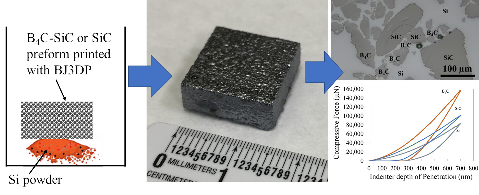
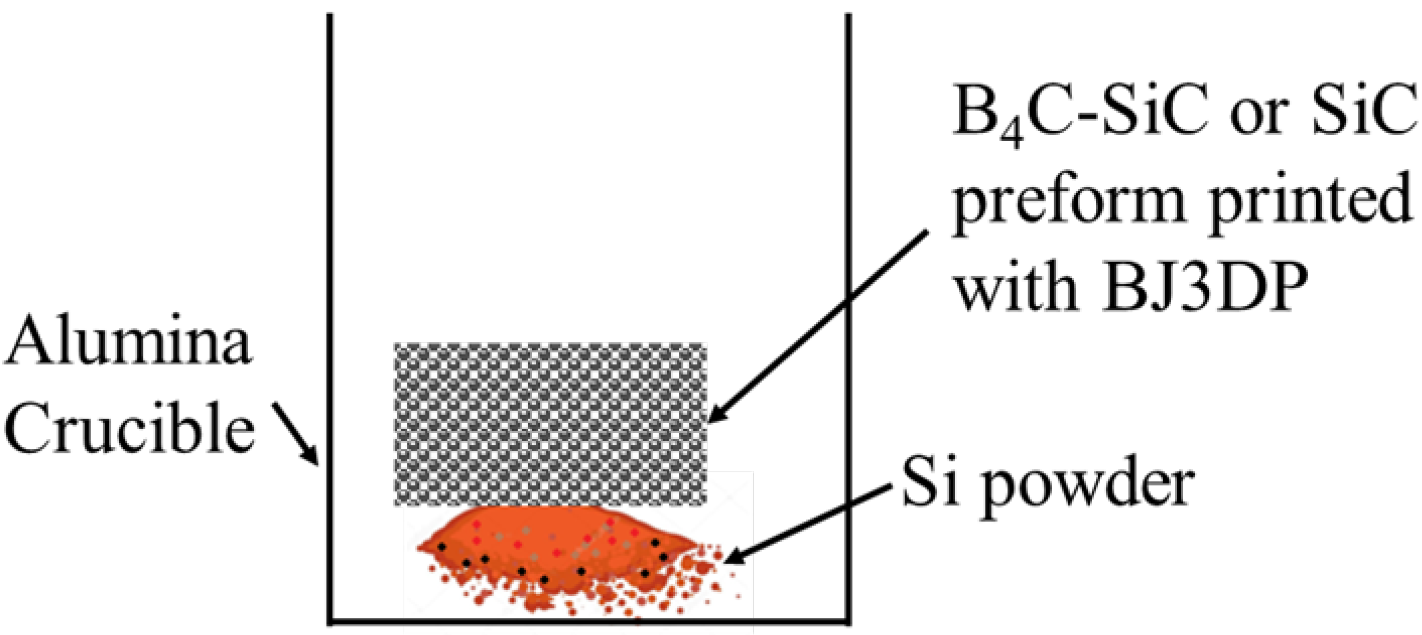
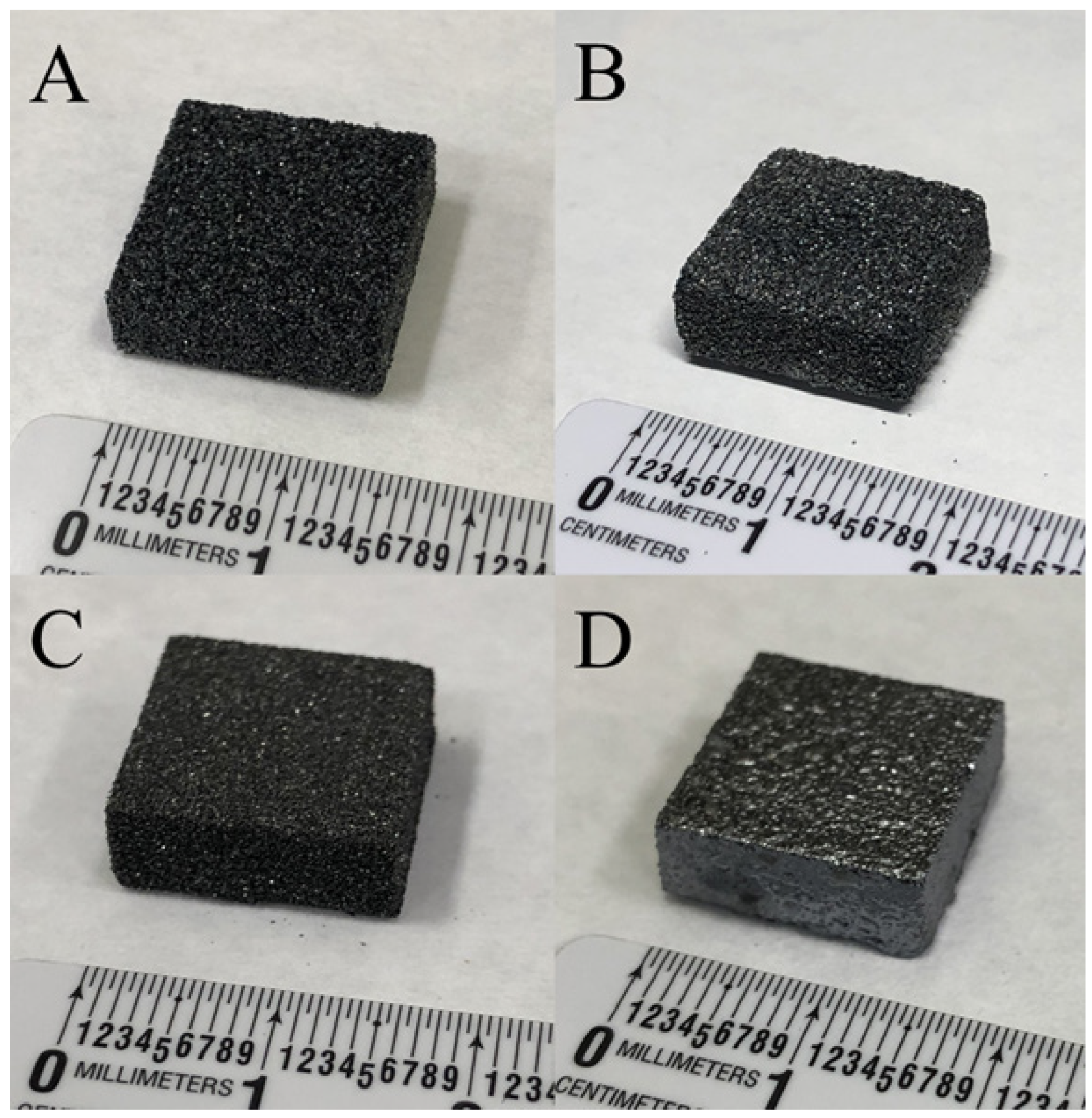
2.2. Processing
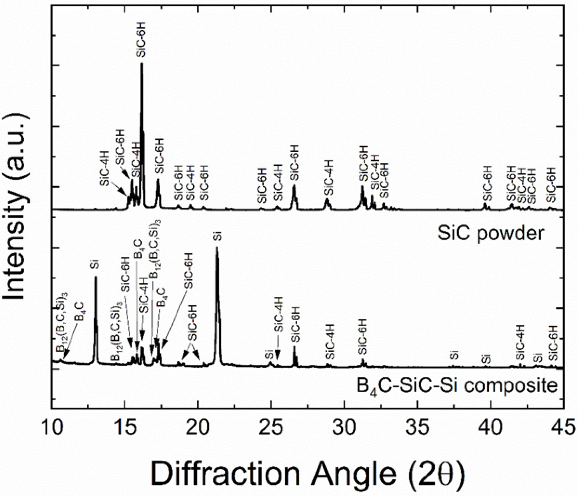
2.3. Characterization
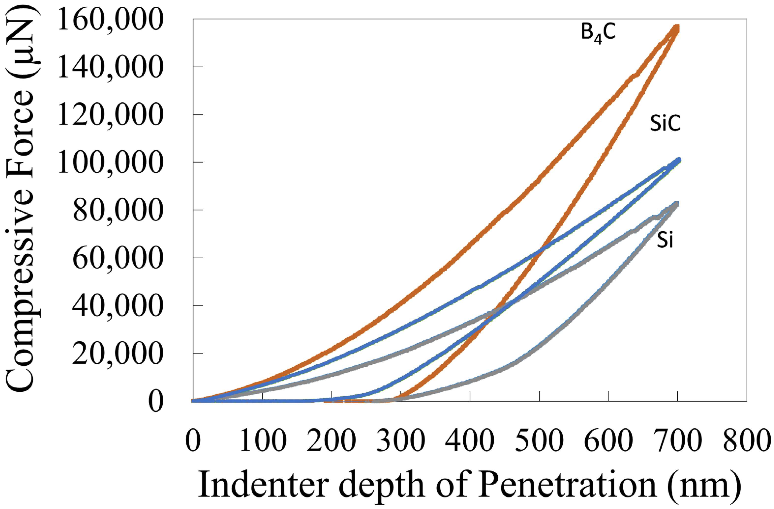
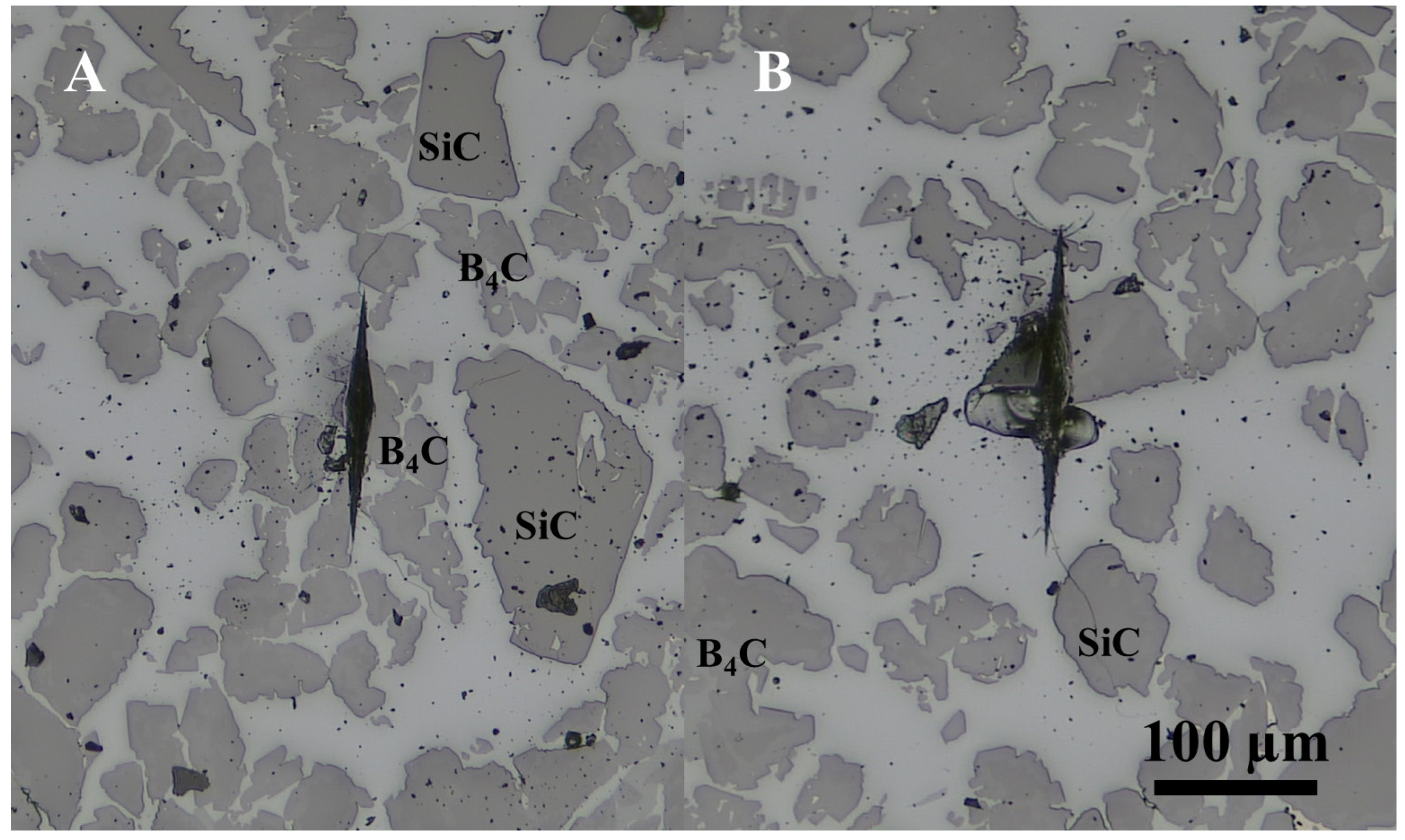
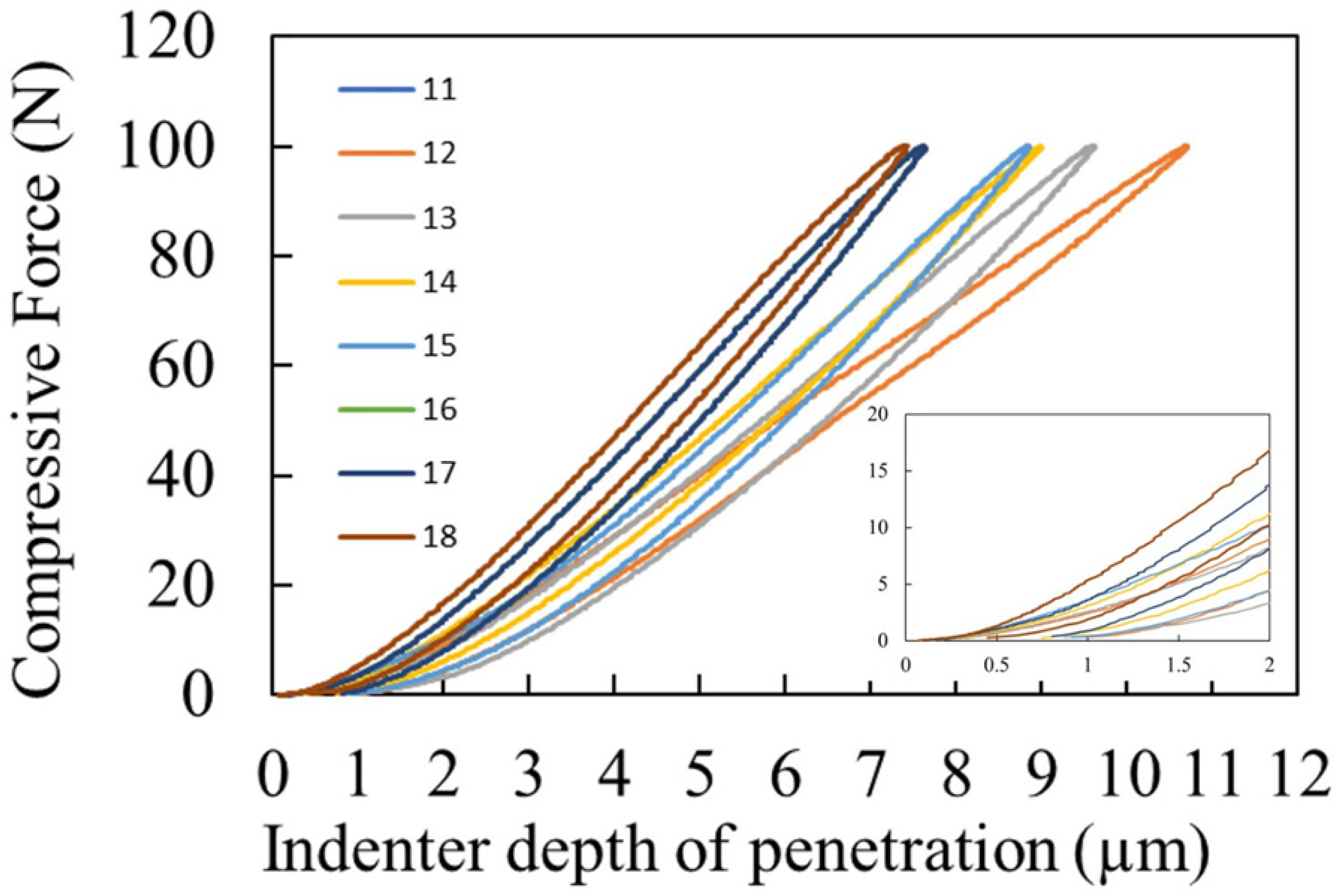
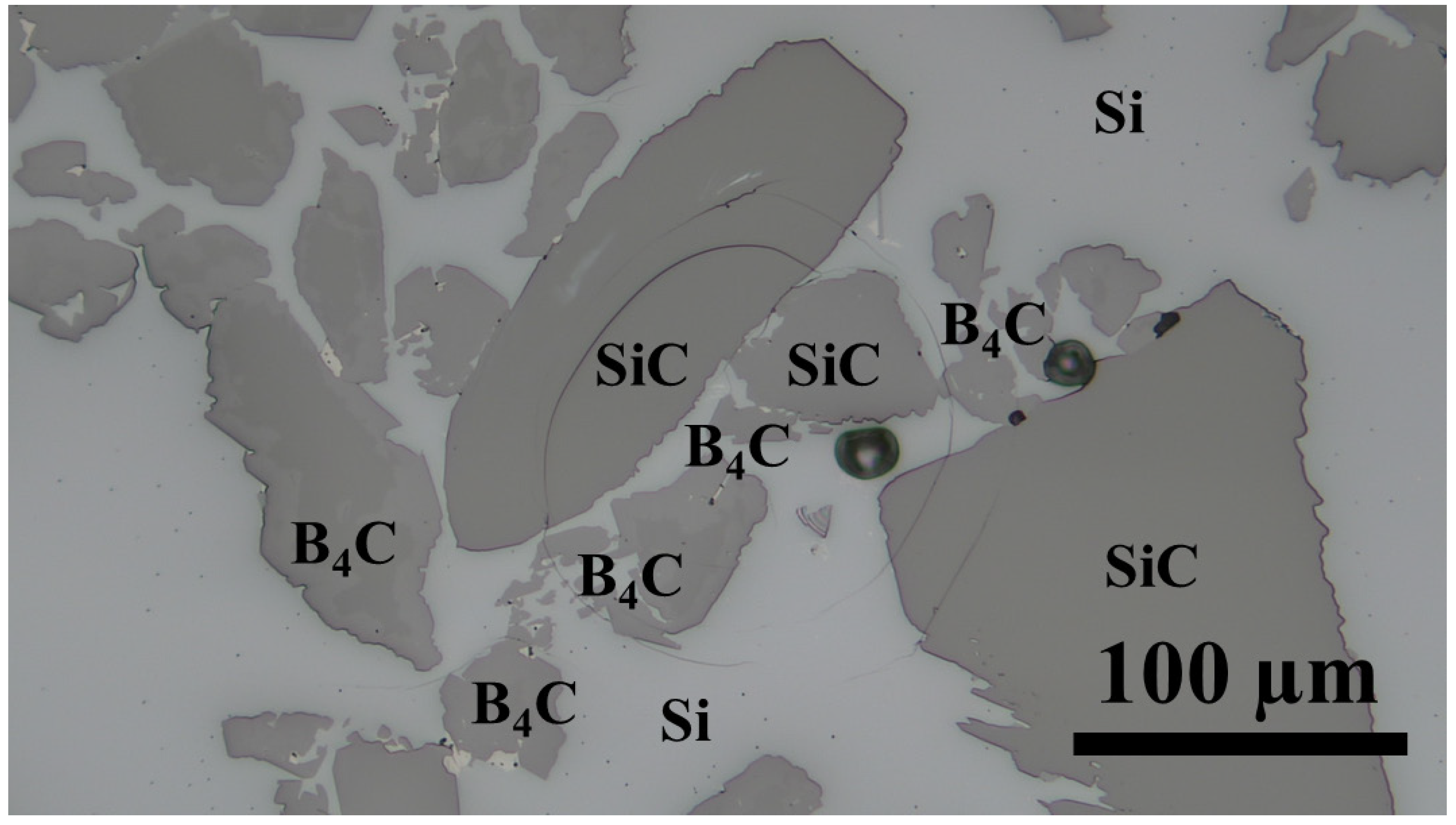
3. Results and Discussion
4. Conclusions
5. Patents
Author Contributions
Funding
Data Availability Statement
Acknowledgments
Conflicts of Interest
Appendix A. Safety Considerations
References
- Popper, P.; Davies, D.G.S. The preparation and properties of self-bonded silicon carbide. Powder Metall. 1961, 4, 113–127. [Google Scholar] [CrossRef]
- Wang, Y.; Tan, S.; Jiang, D. The effect of porous carbon preform and the infiltration process on the properties of reaction-formed SiC. Carbon 2004, 42, 1833–1839. [Google Scholar] [CrossRef]
- Hozer, L.; Lee, J.-R.; Chiang, Y.-M. A Reaction-infiltrated, net-shape SiC composites. Mater. Sci. Eng. A 1995, 195, 131–143. [Google Scholar] [CrossRef]
- Shin, D.-W.; Park, S.S.; Choa, Y.-H.; Niihara, K. Silicon/Silicon Carbide Composites Fabricated by Infiltration of a Silicon Melt into Charcoal. J. Am. Ceram. Soc. 2004, 82, 3251–3253. [Google Scholar] [CrossRef]
- Presas, M.; Pastor, J.Y.; LLorca, J.; de Arellano-López, A.R.; Martínez-Fernández, J.; Sepúlveda, R.E. Mechanical behavior of biomorphic Si/SiC porous composites. Scr. Mater. 2005, 53, 1175–1180. [Google Scholar] [CrossRef]
- Ness, J.N.; Page, T.F. Microstructural evolution in reaction-bonded silicon carbide. J. Mater. Sci. 1986, 21, 1377–1397. [Google Scholar] [CrossRef]
- Sangsuwan, P.; Tewari, S.N.; Gatica, J.E.; Singh, M.; Dickerson, R. Reactive infiltration of silicon melt through microporous amorphous carbon preforms. Metall. Mater. Trans. B 1999, 30, 933–944. [Google Scholar] [CrossRef]
- Whalen, T.J.; Anderson, A.T. Wetting of SiC, Si3N4, and Carbon by Si and Binary Si Alloys. J. Am. Ceram. Soc. 1975, 58, 396–399. [Google Scholar] [CrossRef]
- Nikolopoulos, P.; Los, S.A.P.; Angelopoulos, G.N.; Naoumidis, A.; Grübmeier, H. Wettability and interfacial energies in SiC-liquid metal systems. J. Mater. Sci. 1992, 27, 139–145. [Google Scholar] [CrossRef]
- Molina, J.M.; Prieto, R.; Narciso, J.; Louis, E. The effect of porosity on the thermal conductivity of Al–12 wt.% Si/SiC composites. Scr. Mater. 2009, 60, 582–585. [Google Scholar] [CrossRef]
- Wilhelm, M.; Kornfeld, M.; Wruss, W. Development of SiC–Si composites with fine-grained SiC microstructures. J. Eur. Ceram. Soc. 1999, 19, 2155–2163. [Google Scholar] [CrossRef]
- Roger, J.; Guesnet, L.; Marchais, A.; Le Petitcorps, Y. SiC/Si composites elaboration by capillary infiltration of molten silicon. J. Alloys Compd. 2018, 747, 484–494. [Google Scholar] [CrossRef]
- McCauley, J.W.; Rim, M.P., IV. International Conference on Advanced Ceramics and Glass (2001: Wailea, Ceramic armor materials by design: Proceedings of the Ceramic Armor Materials by Design Symposium. In Proceedings of the Pac Rim IV International Conference on Advanced Ceramics and Glass, Maui, HI, USA, 4–8 November 2001; American Ceramic Society: Westerville, OH, USA, 2002. [Google Scholar]
- Taylor, K.; Palicka, R. Dense Carbide Composite for Armor and Abrasives. U.S. Patent 3,765,300, 16 October 1973. [Google Scholar]
- Panasyuk, A.D.; Oreshkin, V.D.; Maslennikova, V.R. Kinetics of the reactions of boron carbide with liquid aluminum, silicon, nickel, and iron. Sov. Powder Metall. Met. Ceram. 1979, 18, 487–490. [Google Scholar] [CrossRef]
- Hayun, S.; Weizmann, A.; Dariel, M.P.; Frage, N. The Effect of Particle Size Distribution on the Microstructure and the Mechanical Properties of Boron Carbide-Based Reaction-Bonded Composites. Int. J. Appl. Ceram. Technol. 2009, 6, 492–500. [Google Scholar] [CrossRef]
- Hayun, S.; Frage, N.; Dariel, M.P. The morphology of ceramic phases in BxC–SiC–Si infiltrated composites. J. Solid State Chem. 2006, 179, 2875–2879. [Google Scholar] [CrossRef]
- Hayun, S.; Weizmann, A.; Dariel, M.P.; Frage, N. Microstructural evolution during the infiltration of boron carbide with molten silicon. J. Eur. Ceram. Soc. 2010, 30, 1007–1014. [Google Scholar] [CrossRef]
- Mallick, D.; Kayal, T.K.; Ghosh, J.; Chakrabarti, O.P.; Biswas, S.; Maiti, H.S. Development of multi-phase B–Si–C ceramic composite by reaction sintering. Ceram. Int. 2009, 35, 1667–1669. [Google Scholar] [CrossRef]
- Wang, J.; Lin, W.; Jiang, Z.; Duan, L.; Yang, G. The preparation and properties of SiCw/B4C composites infiltrated with molten silicon. Ceram. Int. 2014, 40, 6793–6798. [Google Scholar] [CrossRef]
- Aroati, S.; Cafri, M.; Dilman, H.; Dariel, M.P.; Frage, N. Preparation of reaction bonded silicon carbide (RBSC) using boron carbide as an alternative source of carbon. J. Eur. Ceram. Soc. 2010, 31, 841–845. [Google Scholar] [CrossRef]
- Wong, K.V.; Hernandez, A. A Review of Additive Manufacturing. ISRN Mech. Eng. 2012, 2012, 208760. [Google Scholar] [CrossRef]
- Mostafaei, A.; Elliott, A.M.; Barnes, J.E.; Li, F.; Tan, W.; Cramer, C.L.; Nandwana, P.; Chmielus, M. Binder jet 3D printing—process parameters, materials, properties, and challenges. Prog. Mater. Sci. 2020, 119, 100707. [Google Scholar] [CrossRef]
- Moon, J.; Caballero, A.C.; Hozer, L.; Chiang, Y.-M.; Cima, M.J. Fabrication of functionally graded reaction infiltrated SiC–Si composite by three-dimensional printing (3DPTM) process. Mater. Sci. Eng. A 2001, 298, 110–119. [Google Scholar] [CrossRef]
- Cramer, C.L.; Elliott, A.M.; Lara-Curzio, E.; Flores-Betancourt, A.; Lance, M.J.; Han, L.; Blacker, J.; Trofimov, A.A.; Wang, H.; Cakmak, E.; et al. Properties of SiC-Si made via binder jet 3D printing of SiC powder, carbon addition, and silicon melt infiltration. J. Am. Ceram. Soc. 2021, 101, 5467–5478. [Google Scholar] [CrossRef]
- Fleisher, A.; Zolotaryov, D.; Kovalevsky, A.; Muller-Kamskii, G.; Eshed, E.; Kazakin, M.; Popov, V.V., Jr. Reaction bonding of silicon carbides by Binder Jet 3D-Printing, phenolic resin binder impregnation and capillary liquid silicon infiltration. Ceram. Int. 2019, 45, 18023–18029. [Google Scholar] [CrossRef]
- Oh, J.W.; Park, J.; Nahm, S.; Choi, H. SiC-Si composite part fabrication via SiC powder binder jetting additive manufacturing and molten-Si infiltration. Int. J. Refract. Met. Hard Mater. 2021, 101, 105686. [Google Scholar] [CrossRef]
- Hansen, N. Hall–Petch relation and boundary strengthening. Scr. Mater. 2004, 51, 801–806. [Google Scholar] [CrossRef]
- Ryou, H.; Drazin, J.W.; Wahl, K.J.; Qadri, S.B.; Gorzkowski, E.P.; Feigelson, B.N.; Wollmershauser, J.A. Below the Hall-Petch Limit in Nanocrystalline Ceramics. ACS Nano 2018, 12, 3083–3094. [Google Scholar] [CrossRef]
- Chavoshi, S.Z.; Branicio, P.S.; An, Q. Transition between Hall-Petch and inverse Hall-Petch behavior in nanocrystalline silicon carbide. Phys. Rev. Mater. 2021, 5, 073606. [Google Scholar] [CrossRef]
- Holmquist, T.J.; Wereszczak, A.A. Using Hertzian Indentation to Understand the Strength and Ballistic Resistance of Silicon Carbide. Int. J. Appl. Ceram. Technol. 2010, 7, 625–634. [Google Scholar] [CrossRef]
- Hackett, B.L.; Wereszczak, A.A.; Pharr, G.M. Evaluation of new technique to estimate yield stress in brittle materials via spherical indentation testing. In Proceedings of the 42nd International Conference on Advanced Ceramics and Composites: Ceramic Engineering and Science, Daytona Beach, FL, USA, 21–26 January 2018; pp. 61–71. [Google Scholar]
- Cramer, C.L.; Nandwana, P.; Lowden, R.A.; Elliott, A.M. Infiltration studies of additive manufacture of WC with Co using binder jetting and pressureless melt method. Addit. Manuf. 2019, 28, 333–343. [Google Scholar] [CrossRef]
- Nandwana, P.; Elliott, A.M.; Siddel, D.; Merriman, A.; Peter, W.H.; Babu, S.S. Powder bed binder jet 3D printing of Inconel 718: Densification, microstructural evolution and challenges☆. Curr. Opin. Solid State Mater. Sci. 2017, 21, 207–218. [Google Scholar] [CrossRef]
- Bai, Y.; Williams, C.B. The effect of inkjetted nanoparticles on metal part properties in binder jetting additive manufacturing. Nanotechnology 2018, 29, 395706. [Google Scholar] [CrossRef] [PubMed]
- Bai, Y.; Wagner, G.; Williams, C.B. Effect of Bimodal Powder Mixture on Powder Packing Density and Sintered Density in Binder Jetting of Metals. In International Solid Freeform Fabrication Symposium; University of Texas: Austin, TX, USA, 2015. [Google Scholar]
- Fitzgerald, A.M.; Dauskardt, R.H.; Kenny, T.W. Fracture toughness and crack growth phenomena of plasma-etched single crystal silicon. Sens. Actuators A Phys. 2000, 83, 194–199. [Google Scholar] [CrossRef]
- Dub, S.N.; Kushch, V.I.; Kaidash, O.N.; Sereda, V.P.; Panasyuk, T.S. Initiation of a plastic flow in boron carbide at nanoindentation. J. Superhard Mater. 2015, 37, 8–13. [Google Scholar] [CrossRef]
- Ekici, R.; Apalak, M.K.; Yıldırım, M.; Nair, F. Effects of random particle dispersion and size on the indentation behavior of SiC particle reinforced metal matrix composites. Mater. Des. 2010, 31, 2818–2833. [Google Scholar] [CrossRef]
- Pereyra, R.; Shen, Y.L. Characterization of particle concentration in indentation-deformed metal-ceramic composites. Mater. Charact. 2004, 53, 373–380. [Google Scholar] [CrossRef]
- Wereszczak, A.A.; Morrissey, T.G.; Ferber, M.K.; Bortle, K.P.; Rodgers, E.A.; Tsoi, G.; Montgomery, J.M.; Vohra, Y.; Toller, S. Responses of siliceous materials to high pressure. Adv. Ceram. Armor IX 2013, 1–13. [Google Scholar]
- Wereszczak, A.A.; Johanns, K.E.; Jadaan, O.M. Hertzian ring crack initiation in hot-pressed silicon carbides. J. Am. Ceram. Soc. 2009, 92, 1788–1795. [Google Scholar] [CrossRef]
- Erhard, R. Martens Hardness-More than just hardness testing. VDI BERICHTE 2002, 1685, 385–392. [Google Scholar]
- Jadaan, O.M.; Wereszczak, A.A.; Johanns, K.E.; Daloz, W.L. Weibull effective area for Hertzian ring crack initiation. Int. J. Appl. Ceram. Technol. 2011, 8, 824–831. [Google Scholar] [CrossRef]
- Demir, A. Effect of Nicalon SiC fibre heat treatment on short fibre reinforced β-sialon ceramics. J. Eur. Ceram. Soc. 2012, 32, 1405–1411. [Google Scholar] [CrossRef]
- Frazer, D.; Abad, M.D.; Krumwiede, D.; Back, C.A.; Khalifa, H.E.; Deck, C.P.; Hosemann, P. Localized mechanical property assessment of SiC/SiC composite materials. Compos. Part A Appl. Sci. Manuf. 2015, 70, 93–101. [Google Scholar] [CrossRef]


| Element | SiC Powder | Printed and Debinded SiC | B4C-SiC Powder Blend | Printed and Debinded B4C-SiC |
|---|---|---|---|---|
| Si | 69.3 ± 1.4 | 71.1 ± 1.4 | 29.4 ± 0.6 | 28.7 ± 0.6 |
| C | 29.6 ± 0.6 | 29.0 ± 0.6 | 24.9 ± 0.5 | 26.3 ± 0.5 |
| B | -- | -- | 45.7 ± 0.9 | 45.0 ± 0.9 |
| Printed SiC Preform | Printed SiC-B4C Preform | Infiltrated SiC-Si Composite | Infiltrated B4C-SiC-Si Composite | |
|---|---|---|---|---|
| Dimensions (mm) | 15.2 × 15.1 × 5.1 | 15.1 × 15.1 × 5.1 | 15.2 × 15.1 × 5.1 | 15.2 × 14.9 × 5.1 |
| Density (g/cm3, %TD) | 1.57, 48 | 1.54, 55 | n/a | 2.5, 98.4 |
| Phase | |||
|---|---|---|---|
| B4C Particles | SiC Particles | Si Matrix | |
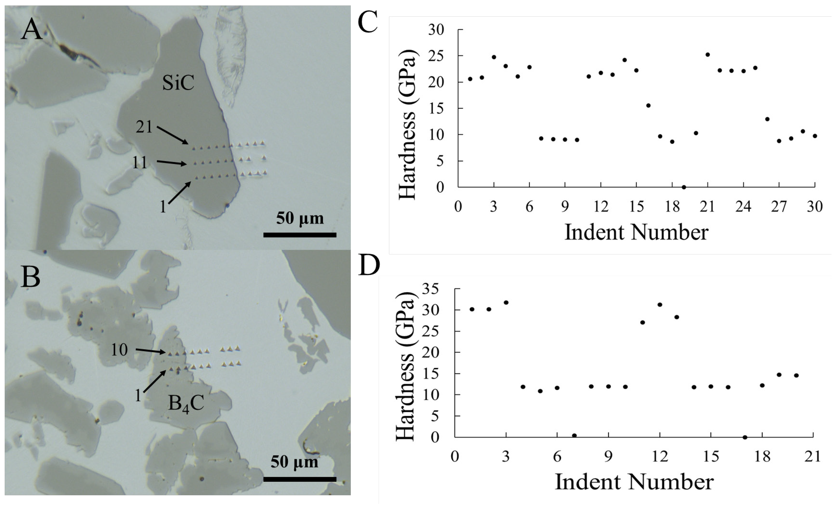
| Vickers hardness on phases (GPa) | 31.8 ± 0.4 | 26.5 ± 0.5 | 9.2 ± 0.3 |
| Nanohardness on phases (GPa) | 29.8 ± 1.3 | 22.3 ± 1.8 | 9.3 ± 0.7 |
| Knoop hardness (GPa) | 10.3 ± 2.0 | ||
| Rockwell C (Spherical) hardness on composite (GPa) | 18.8 ± 2.2 | ||
| Calculated composite hardness by rule of mixtures with Vickers values | 20.3 | ||
Disclaimer/Publisher’s Note: The statements, opinions and data contained in all publications are solely those of the individual author(s) and contributor(s) and not of MDPI and/or the editor(s). MDPI and/or the editor(s) disclaim responsibility for any injury to people or property resulting from any ideas, methods, instructions or products referred to in the content. |
© 2023 by the authors. Licensee MDPI, Basel, Switzerland. This article is an open access article distributed under the terms and conditions of the Creative Commons Attribution (CC BY) license (https://creativecommons.org/licenses/by/4.0/).
Share and Cite
Cramer, C.L.; Cakmak, E.; Unocic, K.A. Hardness Measurements and Interface Behavior of SiC-B4C-Si Multiple Phase Particulate Composites Made with Melt Infiltration and Additive Manufacturing. J. Compos. Sci. 2023, 7, 172. https://doi.org/10.3390/jcs7040172
Cramer CL, Cakmak E, Unocic KA. Hardness Measurements and Interface Behavior of SiC-B4C-Si Multiple Phase Particulate Composites Made with Melt Infiltration and Additive Manufacturing. Journal of Composites Science. 2023; 7(4):172. https://doi.org/10.3390/jcs7040172
Chicago/Turabian StyleCramer, Corson L., Ercan Cakmak, and Kinga A. Unocic. 2023. "Hardness Measurements and Interface Behavior of SiC-B4C-Si Multiple Phase Particulate Composites Made with Melt Infiltration and Additive Manufacturing" Journal of Composites Science 7, no. 4: 172. https://doi.org/10.3390/jcs7040172