Article

Additive Manufacturing of Carbon Fiber Reinforced Epoxy Thermoset with Improved Thermomechanical Properties

1
Department of Aerospace and Mechanical Engineering, The University of Texas at El Paso, El Paso, TX 79968, USA
2
W.M. Keck Center for 3D Innovation, The University of Texas at El Paso, El Paso, TX 79968, USA
3
Aerospace Center, The University of Texas at El Paso, El Paso, TX 79968, USA
4
Turner College of Business, Columbus State University, Columbus, GA 31907, USA
*
Authors to whom correspondence should be addressed.
J. Compos. Sci. 2023, 7(4), 171; https://doi.org/10.3390/jcs7040171
Submission received: 19 March 2023 / Revised: 7 April 2023 / Accepted: 18 April 2023 / Published: 20 April 2023
(This article belongs to the Special Issue Additive Manufacturing of Composites and Nanocomposites)

Abstract

:
Laser Powder Bed Fusion (LPBF) is a widely used additive manufacturing technique for powder-based polymers and metallic materials. Thermoplastics like Polyamide 12 and Polyamide 6 are commonly used in LPBF; thermosetting polymers are gaining attention due to their superior stability. Epoxies are a popular thermoset, but some exhibit low physical properties and brittleness, leading to reduced toughness. The work presented in this paper explores the effect of using short carbon fibers (CF) as additives to epoxy-based thermosetting material on physical and thermomechanical properties. A total of six epoxy thermoset/CF composite powder blends were prepared by varying reinforcing materials weight percentages (0 wt%, 0.3 wt%, 0.6 wt%, 1 wt%, 5 wt%, and 10 wt%). Tensile, four-point bending, and dynamic mechanical analysis (DMA) test samples were printed using the LPBF technique. Significant improvements in the physical and thermomechanical properties were obtained in the thermoset composites with 5 wt% of CF due to good adhesion between reinforcing materials and the matrix and a low level of porosity. Fracture surface analysis was performed via scanning electron microscopy (SEM), which provided insight into the influence of CF on the properties of thermosetting composites. The findings of this research demonstrate the feasibility of improving the inferior physical and thermomechanical properties of 3D-printed CF-reinforced epoxy. With a certain amount of CF reinforcement, Young’s modulus and fracture modulus can be increased by around 52% and 259%, respectively.

1. Introduction

Additive manufacturing (AM) is a process that allows components and parts to be made through the integration of design for manufacturing multiple components and parts by building layer-by-layer. Complex design and mass customization in manufacturing is the most advantageous aspect of AM over any other traditional methods, such as forging and joining for metals. In some cases, it has also shown reduced unit cost over the injection molding process for polymers/plastics when compared [1]. Material Jetting is a category of AM in which specific droplets of feedstock material are intentionally placed or deposited [2,3]. Direct Ink Writing (DIW) printing technology is a type of 3D printing that involves the direct deposition of inks or pastes, which are extruded through a small nozzle, onto a substrate layer by layer to create a 3D object according to the CAD model. DIW can be used to fabricate highly flexible functional materials [4]. Binder Jetting is a 3D printing method in which a liquid adhesive is deliberately applied to connect powdered substances such as metals, polymers, and ceramics [5]. Vat photopolymerization is a technique where light-induced polymerization is used to selectively solidify liquid photopolymer inside a container [6,7,8]. For material extrusion, the material is deliberately released through a nozzle or opening in a selective manner [8]. Sheet Lamination is a method of creating a component by joining sheets of material together [9]. With Direct Energy Deposition, materials are melted and joined together as they are deposited using a focused thermal energy [10]. In LPBF AM, Selective Laser Sintering (SLS) and Selective Laser Melting (SLM) are used on a wide range of powdered materials, from metals, polymers, and ceramics to composites [11,12,13,14]. SLS is dedicated for polymers, and this printing method provides complex shape printability with high resolution over most of other AM techniques [15]. It produces parts with a higher build speed than most other AM techniques, such as fused deposition modeling (FDM). The mechanical properties of features created with SLS have showcased near isotropic mechanical properties [16,17].
SLS 3D printing requires the powder to have a specific range of particle size and distribution, which is manageable; however, it also requires specific thermal and rheological properties, which are severely limited. If the sintering window is too narrow, it cannot be manufactured through SLS. The powder must have specific rheological properties such as low viscosity and low surface tension for a desirable melting; if not, the powder cannot be manufactured [18]. The solution is to blend currently available SLS powders, such as Polyamide 12 (PA12), with another powder, such as Polybutylene Terephthalate (PBT). That can lead to improvements in powder printability and final part properties such as lower porosity, high density, and higher geometric fidelity [19].
Adding reinforcement materials to the SLS powder is the key to improving mechanical properties after 3D printing. In previous research, PA12 was mixed with multi-walled carbon nanotubes before SLS printing. For example, the manufactured parts underwent stress-strain tests showing a higher flexural modulus, ultimate strength, and composite strength than pure PA12 [20]. Jing et al. mixed PA12 with chopped CF before 3D printing, which resulted in an increment of tensile strength, tensile modulus, flexural strength, and flexural modulus [20]. The influence of fiber fraction on the thermal and mechanical properties of thermosetting composites was analyzed by Hall et al. [21].
SLS 3D printing applications have commonly utilized thermoplastic materials like PA12 and PA6. This is because of their crystalline structure, processability, and printability. However, these materials are deficient in polymer inter-chain bonding, which leads to substandard mechanical and thermal properties and relatively low fatigue behavior. Thus, it is crucial to pursue 3D printing of high-performance crosslinked thermosets using SLS technology as an alternative to thermoplastics. This research investigated the SLS 3D printing of CF-reinforced high-temperature epoxy thermosets. Multi stages curing process was introduced for chemical crosslinking of 3D printed green samples. The influence of varying CF amounts in mechanical and thermomechanical properties of thermoset matrix has been investigated. The effects of powder tap density on powder flowability and sample density and, eventually, how those properties influenced mechanical properties was another focus of this research.

2. Experimental Methodology

2.1. Materials

In this experiment, Premium Performance Polymer (PPP) thermoset powder (TIGER Coatings GmbH & Co., 4600 Wels, Austria) with 10–100 μm particle size was used as a polymer matrix. Undesired conglomerate powder particles were removed from the commercially produced PPP by sieving it properly before SLS processing. Short Carbon Fiber (CF) (McMaster-Carr, Elmhurst, IL, USA) with an average 150 μm length and 8 μm diameter were added to the thermoset polymer as a filler reinforcement material.

2.2. Preparation of PPP/CF Composite Powders

The powder sieving was performed using the Gilson SS-15D sieve shaker machine, and standard particle size distribution could be obtained in the desired range (20–80 μm). PPP (Tiger coating) powder was blended with a different weight percentage of CF (0.1 wt%, 0.3 wt%, 1 wt%, 5 wt%, and 10 wt%). Sartorius (Sartorius Corporation, 565 Johnson Avenue Bohemia, NY 11716, USA) weighing machine was used to measure each powder quantity. Bioengineering Inversina (Bioengineering AG, Sagenrainstrasse 7, 8636 Wald, Zürich, Switzerland) mixture machine was used to mix each composite powder to achieve the homogenous distribution of powder particles during the SLS process. The machine was run at 60 rpm for 2 h at room temperature for uniform mixing of powder with filler materials.

2.3. 3D Printing and Curing of PPP/CF Composites

SLS printing of pure thermoset polymer and PPP/CF powder was performed using a Sinterit Lisa 3D Printer (3D Herndon, VA, USA). The printer was equipped with a diode laser of 5 W capacity, and upgraded ‘Sinterit Studio’ software was utilized to prepare the code for the sample. Bed temperatures, laser power, scan speed, geometries, and other parameters in the printing process were adjusted using the software (Table 1). The bed temperature was set at 60 °C considering the melting point of the polymer matrix material. Optimizing the parameters was done by evaluating the dimensional accuracy of the printed green part.
The printed green PPP/CF samples were cured in a force convection oven (Lab Companion, Jeio Tech, Daejeon, South Korea) to make them stable with proper cross-linking of the molecular structures. Each part was cured in four stages per the powder supplier’s suggested scheduling to ensure dimensional accuracy after complete curing. The uncured printed parts were immersed in the Al2O3 salt bath during the curing process to promote uniform heat distribution and maintain the shape of the samples during curing. The curing schedule recommended by the powder supplier is shown in Table 2.

2.4. Characterization

2.4.1. Thermal Property Analysis of PPP Matrix Material

The PPP polymer matrix was formulated from different resins, hardness, additives, pigments, and fillers (fibers and others). To investigate the matrix material’s thermal stability and glass transition point (Tg) before and after curing, thermogravimetric analysis (TGA) and differential scanning calorimetry (DSC) were performed.
TGA determined the thermal degradation of PPP uncured and cured printed samples. The test was performed using a TGA 55 (TA instruments, New Castle, DE, USA) with a weighing accuracy of ±0.01% and temperature accuracy of ±1 °C. The data was analyzed by degradation onset temperature (DOT), defined as the temperature at which one wt% loss occurred. TGA scans were performed from 25 to 700 °C with a heating rate of 5 °C/min according to the ASTM standard E1131 [22]. The sample purge rate was 60 mL/min, and the balance purge rate was 40 mL/min under the Nitrogen flow of 30 psi. A sample in the weight range of 5 to 8 mg was placed in a high-temperature platinum pan, and the data was analyzed using TA Instrument’s Trios software.
DSC was performed to identify the glass transition temperature (Tg) and degree of curing of PPP printed samples. Discovery 250 DSC instrument (TA instrument, New Castle, DE, USA), having a temperature accuracy of ±0.1 °C, was used for DSC analysis. The test samples were sealed using aluminum T-zero pans and lids to avoid heating and cooling sequence contamination. Initially, the temperature was equilibrated at 25 °C and then ramped at a rate of 5 °C/min, from 25 to 240 °C. The temperature for DSC analysis was chosen based on TGA to avoid sample degradation within the DSC test chamber. Trios software was used for DSC analysis.

2.4.2. Dynamic Mechanical Analysis of 3D Printed PPP/CF Composites

After curing printed samples (curing schedule presented in Table 2), Dynamic Mechanical Analysis (DMA) was performed to determine their Storage Modulus (G′), Loss Modulus (G″), and Damping factor (tan δ). The samples were fabricated according to the ASTM D4065 standard [23]. DMA analysis was performed using DMA 850 machine (purchased from TA instrument, New Castle, DE, USA) possessing ±1% modulus precision. Samples for DMA testing were printed 4 mm longer than the ASTM standard to ensure firm gripping of the samples while tested in the DMA machine. The temperature of the DMA analyzer was ramped from 30 to 220 °C at a constant heating rate of 3 °C/min, where the test frequency and amplitude were set at 1 Hz and 20 μm, respectively, to remain in the linear viscoelastic region.

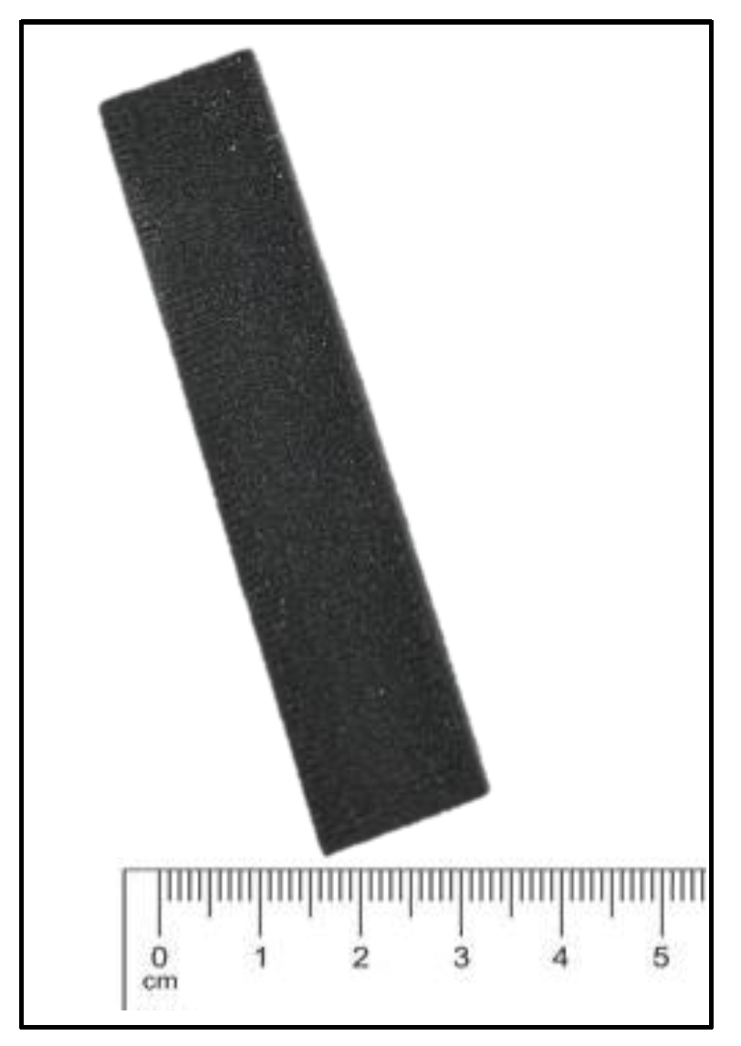
2.4.3. Mechanical Testing of 3D Printed PPP/CF Composites

Tensile testing of the cured samples was performed using a universal testing machine (Model SM-1000-38) (ADMET, Norwood, MA 02062, USA) with a maximum capacity of 4.5 kN and equipped with an MTESTQuattro servo controller. The printed samples were fabricated according to the ASTM D638 standard for the tensile test. The displacement rate of 1 mm/min was used to pull the sample during the testing. The following equation calculated the tensile modulus,
Y o u n g s   M o d u l u s = s t r e s s s t r a i n
Four-point bending test (FPB) was performed to measure the flexural modulus of the composite printed parts. The specimens for this test were printed according to the ASTM D6272 standard [24]. All the samples were printed in a flatwise direction. The same load frame was used for this testing with a crosshead speed of 1 mm/min. Young’s modulus value was obtained from the average value of five samples.

2.4.4. Scanning Electron Microscopy of 3D Printed PPP/CF Composites

Scanning Electron Microscopy (SEM) was accomplished using Phenom ProX desktop SEM (Thermo Fisher Scientific, Achtseweg Noord 5, 5651 GG Eindhoven, The Netherlands) to analyze the PPP matrix powder morphology and particle sizes. Additionally, PPP/CF particle morphology and cross-sectional view of the cured samples were investigated using SEM. CF particle distribution in the thermoset matrix was analyzed for each composition of PPP/CF samples. Gold sputtering was performed to prepare samples for SEM analysis to achieve a high-resolution image of the PPP/CF samples by making the sample conductive and avoiding charging. A 108 auto/SE Sputter Coater (TED PELLA, Inc., Redding, CA, USA) was used for gold sputtering, and 10-micron thickness gold was deposited on the sample with a nitrogen flow of 0.3 psi.

2.4.5. Powder Tap Density and Sample Density

The tap density of PPP/CF powders with different proportions of CF (0 wt%, 0.1 wt%, 0.3 wt%, 1 wt%, 5 wt%, and 10 wt%) and cured sample density were calculated. The measurement was performed using a vernier caliper, Sartorius weighing machine, and a graduated glass cylinder. Composites were carefully poured into a 100 mL graduated glass cylinder to measure the tap density. The powder was compacted by tapping the glass cylinder filled with powder. The weighing machine recorded the weight (gm) of the powder. Powder tap density was measured from the powder weight to the volume ratio. Sample density was measured after fully curing the sample from the mass and volume of the samples. The sample density value was obtained from the average density of five tapped samples.

3. Result and Discussion

3.1. Particle Morphology of PPP Matrix Material

For successful SLS printing of powder particles, the powder should be spherical having good flowability. Figure 1A represents the PPP thermoset powder received from the vendor, and the powder particle morphology was investigated by SEM analysis (Figure 1B). The particle size was 10–100 μm, and most of them were irregular in shape.

3.2. Thermal Properties of PPP Matrix Material

The thermal stability of the PPP printed sample was analyzed from TGA, DSC, DMA, and FTIR analysis. The TGA (Figure 2A) indicates that 1% weight loss from the uncured sample occurred at 222.6 °C, called the degradation onset temperature (DOT) for uncured printed PPP powder. On the other hand, slower degradation was noticed in fully cured printed samples due to their molecular crosslinking, resulting in higher thermal stability than the uncured samples. DOT for fully cured samples was obtained at 257 °C.
DSC analysis was carried out to prove the thermal stability of 3D printed PPP thermoset after curing. In Figure 3, uncured and cured 3D printed samples are indicated by blue and red dotted lines, respectively. The uncured model represents an endothermic peak at 94.55 °C which refers to the glass transition point (Tg). The red dotted line indicates that the fully cured sample shows an endothermic peak at 173.26 °C which denotes the melting point of thermoplastic additives added to the PPP epoxy thermoset. As the chemical crosslinking in the epoxy thermoset advanced with the curing process, thermal stability also improved after fully curing the 3D-printed PPP samples. This phenomenon is verified by the exothermic peak shown by the blue dotted line. The DSC curve for the uncured sample is represented by a blue dotted line that shows an exothermic peak at 197.93 °C, and the area under the curve attributes the enthalpy required for the curing reaction. On the other hand, the red line does not show any exothermic peaks because the fully cured sample does not need any enthalpy for further molecular cross-linking. The similar nature of thermoset polymer during DSC analysis was researched previously [25,26].

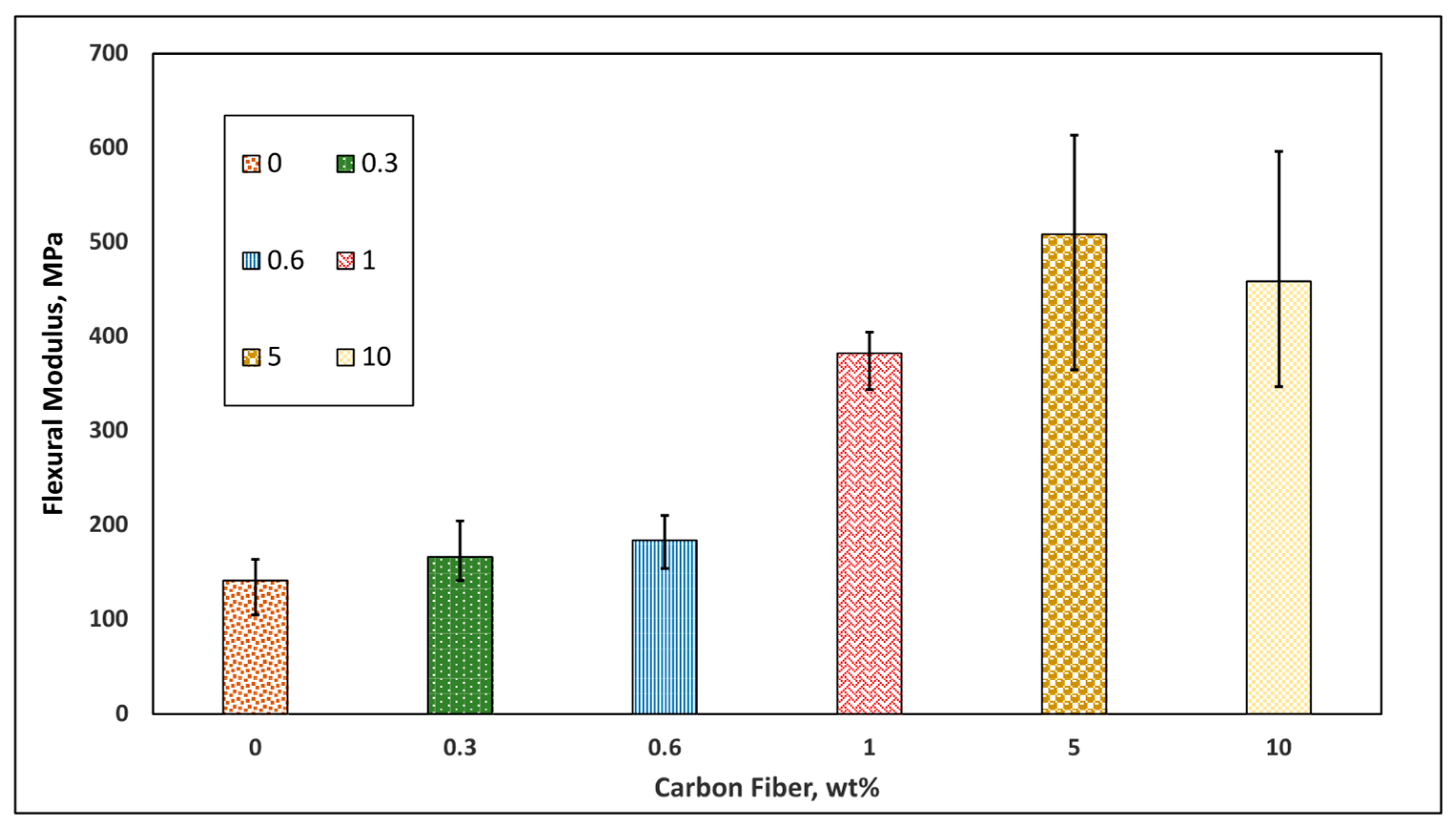
3.3. Effect of Carbon Fiber on Mechanical Properties of 3D Printed Parts

Figure 4 shows how different amounts of CF affect the mechanical properties of SLS-printed thermosets. Pure PPP showed the lowest Young’s modulus of 86 MPa, while a sudden modulus increment occured when the CF amount increased from 0.3 wt% to 0.6 wt%. Continuous increment of CF blended with PPP improved Young’s modulus. The highest Young’s modulus of 131.13 MPa was obtained with 5 wt% CF content, 52.4% higher than pure PPP. Epoxy thermoset cured samples with 10 wt% CF represented a mechanical performance deterioration by 29% lower modulus than 5 wt% CF/PPP samples. This phenomenon can be described by SEM images of intersections of the samples explained in Section 3.6.
Four-point bending flexural tests were conducted to compare the flexural properties of the specimens blended with different CF content. The bar chart (Figure 5) shows that pure PPP represented only 141.79 MPa of flexural modulus. Adding 1 wt% CF drastically improved the flexural modulus of 405.06 MPa. Adding 5 wt% of CF with an epoxy thermoset resulted in the most prominent average flexural modulus of 508.5 MPa, 3.6 times higher than the pure cured samples. After adding more than 5 wt% of CF with PPP, the flexural modulus dropped slightly due to increased porosity in the samples, as shown in SEM analysis.

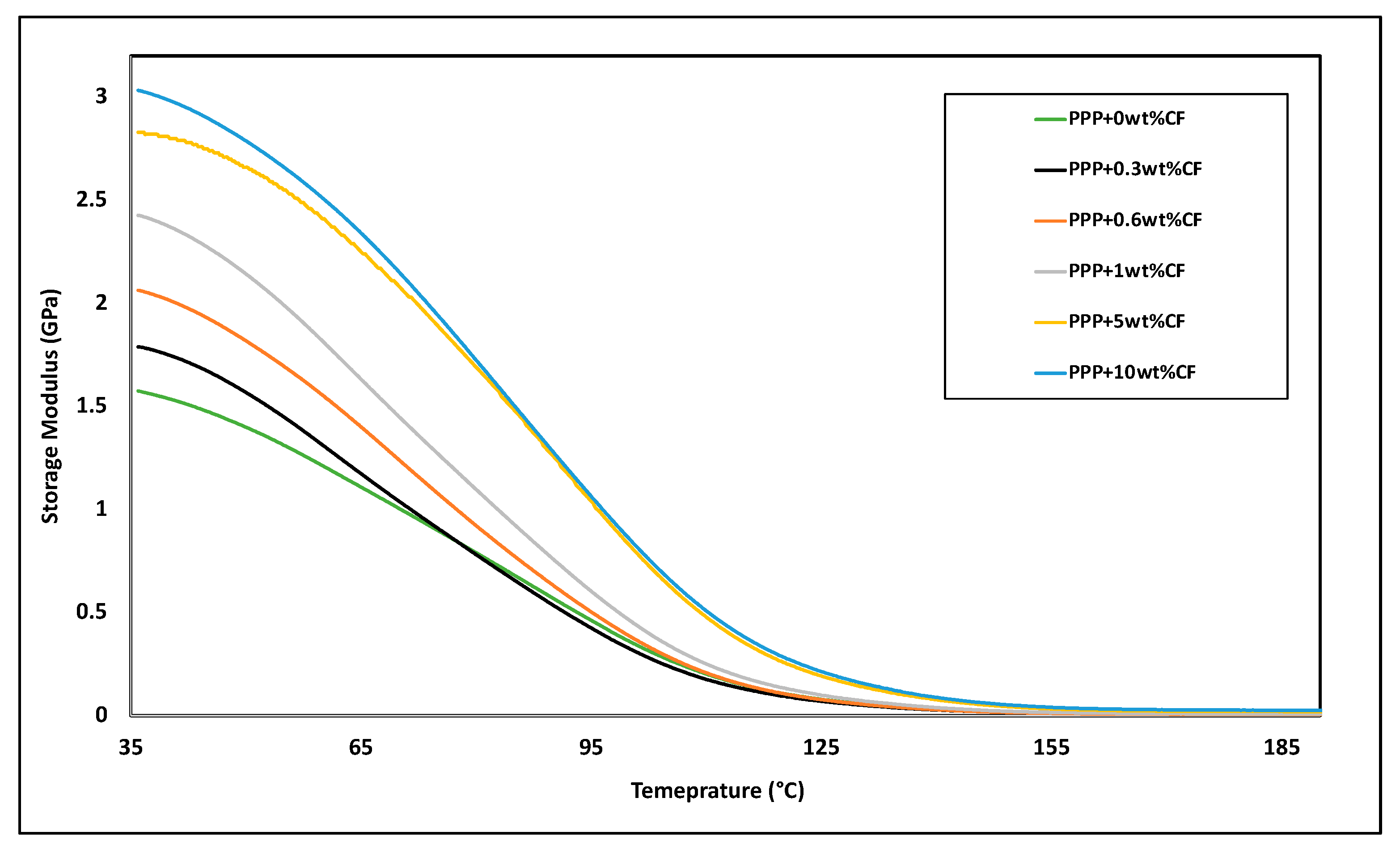
3.4. Effect of Carbon Fiber on Thermomechanical Properties of 3D Printed Parts

DMA was performed to observe the effect of CF content on the thermomechanical properties of 3D-printed cured samples. A fully cured 3D-printed PPP/CF composite sample is shown in Figure 6. The bar chart in Figure 7 shows that the storage modulus of composites increased due to the addition of CF content. Adding fibers to the polymer matrix made an excellent stress transfer at the interface. This stress transfer between the matrix and fibers was primarily responsible for the rise in storage modulus as the interface area increased with the increment of CF content in the epoxy thermoset. Additionally, the storage modulus of composites improved when interactions between the fiber-fiber and fiber-matrix constrained the motions of polymer chains [27,28]. When the temperature increased, there was no longer any stress transfer between the fiber and matrix because composite matrix components were more mobile and began to move from one component to another [29]. Therefore, it was evident that the composites’ storage modulus dropped due to the temperature rise.
Figure 8 shows that the loss modulus of composites dropped initially as the CF concentration increased. However, it increased at a higher concentration of CF content in the PPP thermoset precisely when it was 1 wt% and more. Loss modulus denotes the material’s capacity to release energy as heat or molecular rearrangements during the deformation [28]. Equal or higher than 1 wt% of reinforcing fibers were incorporated into the matrix, and the flow of the polymer chains was slower. In addition, higher thermal properties, such as the conductivity of CF, increased the overall heat dissipation of the composites, resulting in a higher loss modulus. With less than 1 wt% of fiber loading, there is no overlapping of reinforcement materials. Therefore, it did not contribute to slowing down the flow resulting in a low loss modulus. Maximum heat dissipation happens when the loss modulus reaches its maximum value [27,28]. The loss modulus of composites decreased with rising temperature after this maximum value for all PPP/CF composites. The loss modulus reveals how viscous the polymer is, and materials usually become less viscous as the temperature rises [27]. At 10 wt% CF in PPP thermosets with high fiber content in PPP thermosets, the porosity was relatively higher, and the matrix material was relatively less to create viscosity at low temperatures, as shown in Section 3.6. The rising porosity was the reason of showing a lower loss modulus initially at low temperatures in fully cured 10 wt% CF/PPP samples (Figure 8).
The damping factor (tanδ) is the proportion of loss modulus to storage modulus, and the impact of CF content on the damping factor is shown in Figure 9. When a polymer is heated to the glass transition temperature (Tg), the tan δ value is at its highest [30]. Figure 9 represents that the Tg values of CF reinforced composites did not vary while CF content increased; however, the damping factor gradually decreased with increasing wt% of CF presence. This phenomenon indicated that with higher CF content, composites’ energy absorbability was growing in terms of their ability to disperse energy, and elasticity to the viscous response of the viscoelastic material was improved during the sinusoidal deformation. A similar trend was observed in the CF-reinforced polyamide 6 composites [29].

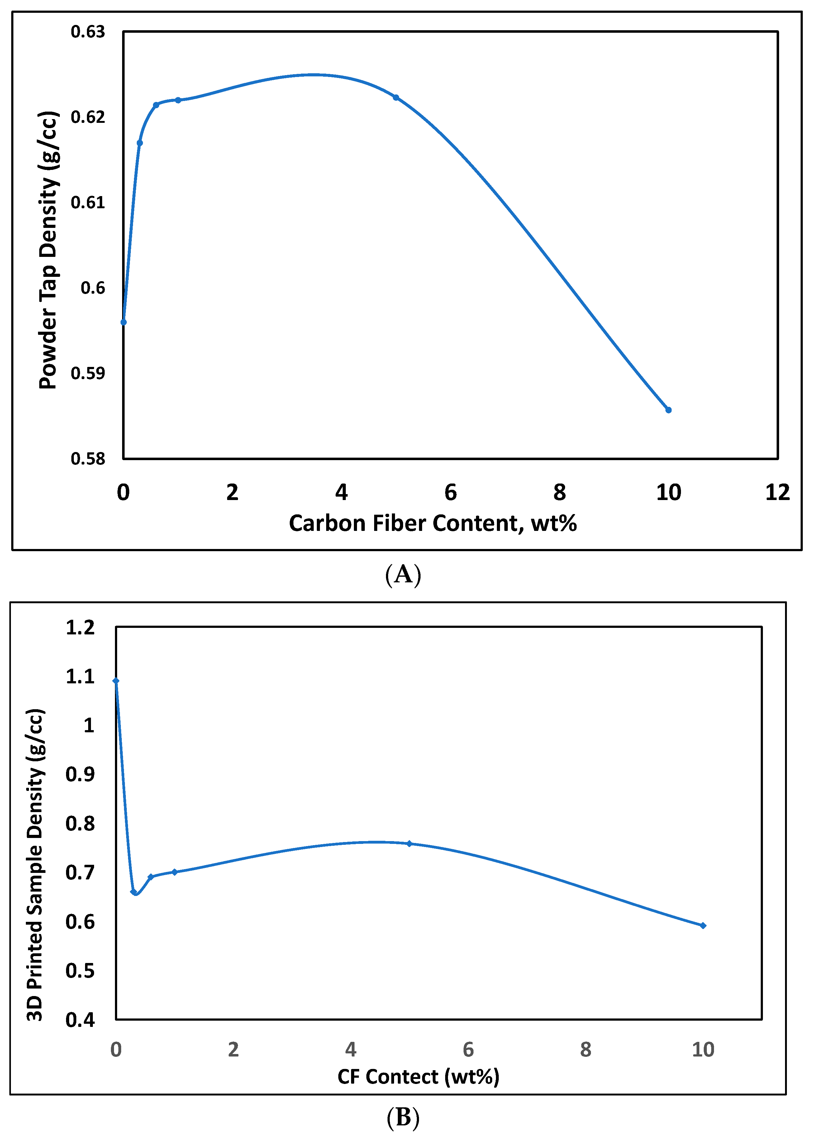
3.5. Powder Tap Density and Sample Density of PPP/CF Composites

Powder tap density at different CF content is shown in Figure 10A. It was found that with the increment of CF, the tap density of composites powder was improved, and the highest density was 0.6214 g/cc, obtained when 5 wt% CF was incorporated into PPP. An increment of tap density indicates a low angle of repose and a high powder flowability [29]. Good powder flowability resulted in low void gaps during the SLS printing process, thus a smaller number of pores in 3D-printed green and fully cured samples. Therefore, the density of fully cured PPP/CF samples increased with the content of CF (Figure 10B) as the powder tap density improved with the same trend (Figure 10A). Fully cured 5 wt% CF blended PPP represented the highest density (0.758 g/cc), and the sample density dropped after that as powder tap density decreased. The CF content in the 10 wt% CF/PPP powder blend is too high to fill out the void gap created with matrix materials as the PPP and CF powders were different in shape, as shown in SEM images. That could be the reason for the low tap density of powder which was composed of PPP with 10 wt% CF. As 10 wt% CF created low tap density, it showed low flowability during the SLS process resulting in low sample density (Figure 10B) and poor mechanical performance.

3.6. Fracture Interface Observation of 3D Printed Samples

Fracture interfaces were observed after tensile testing and four-point bending testing. Section 3.1 shows that the mechanical properties of samples deteriorated after adding more than 5 wt% of CF to the epoxy thermoset. SEM analysis was used to investigate this phenomenon by exploring the specimen porosity and interfacial adhesion between CF and thermoset matrix (Figure 11C–H). Figure 11A,B show SEM of pure PPP thermoset and short CF powders. In SEM analysis, relatively higher amounts and more significant porosity were found at PPP thermosets having 10 wt% CF (Figure 11H), thus resulting in poor mechanical performance. Although the fracture interfaces of the samples having 0 wt%, 0.3 wt%, 0.6 wt%, and 1wt% CF showed relatively low porosity (Figure 11C–F), the interfacial area between CF and thermosets matrix was low because of having a smaller amount of CF. Therefore, low CF content samples resulted in low mechanical performance. From the SEM micrographs, Figure 11G indicates that 5% CF content shows good adhesion between reinforcing materials and matrix and has a low amount of porosity that resulted in the best Young’s and flexural moduli.

4. Conclusions

In this research, we achieved the goal of 3d printing high-strength CF-reinforced thermosetting composites with high thermomechanical properties using SLS 3D printing. Effects on sample density, tensile properties, flexural properties, and thermomechanical properties of the specimens were investigated. Fracture interfaces were analyzed through SEMs. Based on the data set, the following conclusions were drawn from the study-
(a)
Compared with pure thermosetting plastics, fiber addition to polymer thermosetting matrices can improve Young’s modulus, flexural modulus, tap density, and sample density up to a certain amount (5 wt%) of CF.
(b)
Adding CF increased the storage modulus, loss modulus, and damping factor properties. Nevertheless, CF reinforcement has no impact on Tg points.
(c)
Specimen with 5 wt% CF had the most significant mean value of Young’s modulus and flexural modulus, which are 52.47% and 258.63% higher than the pure specimen, respectively.
(d)
SEM images revealed that specimens with higher than 5 wt% CF had severe porosity and poor wetting between CF and epoxy matrix, decreasing mechanical performance.
(e)
Powder tap density impacts powder flowability and sample density after the curing of the specimens. The tap density of epoxy thermoset powder and 3D printed fully cured sample density was improved by including CF reinforcement material up to 5 wt%.

Author Contributions

Conceptualization, M.S.H. and Y.L.; methodology M.S.H., A.D., J.M. and M.S.M.; software, M.S.H.; validation, M.S.H., C.M., S.Z. and S.G.G.; formal analysis, M.S.H.; investigation, M.S.H.; resources, Y.L.; data curation, M.S.H.; writing—original draft preparation, M.S.H. and A.D.; writing—review and editing, M.S.H.; visualization, Y.L.; supervision, Y.L. and J.C.H.; project administration, Y.L.; funding acquisition, Y.L. All authors have read and agreed to the published version of the manuscript.

Funding

This research received funding from Department of Energy [grant No. DE-NA-0004051].

Data Availability Statement

Data is unavailable due to privacy or ethical restrictions.

Acknowledgments

This work has received funding from the Minority Serving Institution Partnership Program (MSIPP). The authors gratefully acknowledge the support from Department of Energy.

Conflicts of Interest

The authors declare no conflict of interest.

References

  1. Pereira, T.; Kennedy, J.V.; Potgieter, J. A comparison of traditional manufacturing vs additive manufacturing, the best method for the job. Procedia Manuf. 2019, 30, 11–18. [Google Scholar] [CrossRef]
  2. Yap, Y.L.; Wang, C.; Sing, S.L.; Dikshit, V.; Yeong, W.Y.; Wei, J. Material jetting additive manufacturing: An experimental study using designed metrological benchmarks. Precis. Eng. 2017, 50, 275–285. [Google Scholar] [CrossRef]
  3. Regis, J.E.; Renteria, A.; Hall, S.E.; Hassan, S.; Marquez, C.; Lin, Y. Recent Trends and Innovation in Additive Manufacturing of Soft Functional Materials. Materials 2021, 14, 4521. [Google Scholar] [CrossRef]
  4. Hassan, S.; Zaman, S.; Rodriguez, A.; Molina, L.; Dominguez, C.E.; Morgan, R.; Bernardin, J.; Lin, Y. Direct ink write 3D printing of wave propagation sensor. Flex. Print. Electron. 2022, 7, 045011. [Google Scholar] [CrossRef]
  5. Ziaee, M.; Crane, N. Binder Jetting: A Review of Process, Materials, and Methods. Fac. Publ. Available online: https://scholarsarchive.byu.edu/facpub/5357 (accessed on 1 August 2019).
  6. Pagac, M.; Hajnys, J.; Ma, Q.-P.; Jancar, L.; Jansa, J.; Stefek, P.; Mesicek, J. A Review of Vat Photopolymerization Technology: Materials, Applications, Challenges, and Future Trends of 3D Printing. Polymers 2021, 13, 598. [Google Scholar] [CrossRef]
  7. Hassan, S.; Chavez, L.A.; Chou, C.-C.; Hall, S.E.; Tseng, T.-L.; Lin, Y. Mechanical response of shape-recovering metamaterial structures fabricated by additive manufacturing. Mater. Res. Express 2021, 8, 115801. [Google Scholar] [CrossRef]
  8. ISO/ASTM 52900:2021(en). Additive Manufacturing—General Principles—Fundamentals and Vocabulary. Available online: https://www.iso.org/obp/ui/#iso:std:iso-astm:52900:ed-2:v1:en (accessed on 2 April 2023).
  9. Frketic, J.; Dickens, T.; Ramakrishnan, S. Automated manufacturing and processing of fiber-reinforced polymer (FRP) composites: An additive review of contemporary and modern techniques for advanced materials manufacturing. Addit. Manuf. 2017, 14, 69–86. [Google Scholar] [CrossRef]
  10. Singh, D.D.; Arjula, S.; Reddy, A.R. Functionally Graded Materials Manufactured by Direct Energy Deposition: A review. Mater. Today Proc. 2021, 47, 2450–2456. [Google Scholar] [CrossRef]
  11. Diaz, J.C.; Watanabe, K.; Rubio, A.; De La Cruz, A.; Godinez, D.; Nabil, S.T.; Murr, L.E.; Wicker, R.B.; Arrieta, E.; Medina, F. Effect of Layer Thickness and Heat Treatment on Microstructure and Mechanical Properties of Alloy 625 Manufactured by Electron Beam Powder Bed Fusion. Materials 2022, 15, 7767. [Google Scholar] [CrossRef] [PubMed]
  12. Hassan, S.; Billah, K.M.M.; Hall, S.E.; Sepulveda, S.; Regis, J.E.; Marquez, C.; Cordova, S.; Whitaker, J.; Robison, T.; Keating, J.; et al. Selective Laser Sintering of High-Temperature Thermoset Polymer. J. Compos. Sci. 2022, 6, 41. [Google Scholar] [CrossRef]
  13. Chavez, L.A.; Ibave, P.; Hassan, S.; Hall-Sanchez, S.E.; Billah, K.M.M.; Leyva, A.; Marquez, C.; Espalin, D.; Torres, S.; Robison, T.; et al. Low-temperature selective laser sintering 3D printing of PEEK-Nylon blends: Impact of thermal post-processing on mechanical properties and thermal stability. J. Appl. Polym. Sci. 2022, 139, 52290. [Google Scholar] [CrossRef]
  14. Aversa, A.; Lorusso, M.; Cattano, G.; Manfredi, D.; Calignano, F.; Ambrosio, E.P.; Biamino, S.; Fino, P.; Lombardi, M.; Pavese, M. A study of the microstructure and the mechanical properties of an Al Si Ni alloy produced via selective laser melting. J. Alloys Compd. 2017, 695, 1470–1478. [Google Scholar] [CrossRef]
  15. Hassan, S.; Billah, K.M.M.; Hall, S.E.; Sepulveda, S.; Regis, J.; Marquez, C.; Cordova, S.; Shafirovich, E.; Lin, Y. Selective laser sintering of high temperature thermoset. In Behavior and Mechanics of Multifunctional Materials XVI; SPIE: Bellingham, DA, USA, 2022; Volume 12044, pp. 58–78. [Google Scholar] [CrossRef]
  16. Kafle, A.; Luis, E.; Silwal, R.; Pan, H.M.; Shrestha, P.L.; Bastola, A.K. 3D/4D Printing of Polymers: Fused Deposition Modelling (FDM), Selective Laser Sintering (SLS), and Stereolithography (SLA). Polymers 2021, 13, 3101. [Google Scholar] [CrossRef]
  17. Mehdipour, F.; Gebhardt, U.; Kästner, M. Anisotropic and rate-dependent mechanical properties of 3D printed polyamide 12—A comparison between selective laser sintering and multi jet fusion. Results Mater. 2021, 11, 100213. [Google Scholar] [CrossRef]
  18. Schmid, M.; Amado, A.; Wegener, K. Polymer powders for selective laser sintering (SLS). In AIP Conference Proceedings; AIP Publishing LLC: Melville, NY, USA, 2015. [Google Scholar] [CrossRef]
  19. Greiner, S.; Wudy, K.; Lanzl, L.; Drummer, D. Selective laser sintering of polymer blends: Bulk properties and process behavior. Polym. Test. 2017, 64, 136–144. [Google Scholar] [CrossRef]
  20. Jing, W.; Hui, C.; Qiong, W.; Hongbo, L.; Zhanjun, L. Surface modification of carbon fibers and the selective laser sintering of modified carbon fiber/nylon 12 composite powder. Mater. Des. 2017, 116, 253–260. [Google Scholar] [CrossRef]
  21. Hall, S.E.; Centeno, V.; Favela, S.; Lopez, A.; Gallardo, A.; Pellicotte, J.; Torres, Y.; Coverdell, D.; Torres, S.; Choudhuri, A.; et al. Mechanical Properties of High-Temperature Fiber-Reinforced Thermoset Composites with Plain Weave and Unidirectional Carbon Fiber Fillers. J. Compos. Sci. 2022, 6, 213. [Google Scholar] [CrossRef]
  22. Standard Test Method for Compositional Analysis by Thermogravimetry. Available online: https://www.astm.org/e1131-20.html (accessed on 12 June 2022).
  23. Standard Practice for Plastics: Dynamic Mechanical Properties: Determination and Report of Procedures. Available online: https://www.astm.org/d4065-20.html (accessed on 10 October 2022).
  24. Flexural Test Composites Four-Point Bending by ASTM D6272. Available online: https://www.intertek.com/polymers/composites/flexural-test-composites-four-point-bending-astm-d6272/ (accessed on 10 October 2022).
  25. Kinetics of Carbon Nanotube-Loaded Epoxy Curing: Rheometry, Differential Scanning Calorimetry, and Radio Frequency Heating|Request PDF. Available online: https://www.researchgate.net/publication/348208730_Kinetics_of_carbon_nanotube-loaded_epoxy_curing_Rheometry_differential_scanning_calorimetry_and_radio_frequency_heating (accessed on 9 June 2022).
  26. Sasaki, T.; Moriuchi, H.; Yano, S.; Yokota, R. High thermal stable thermoplastic–thermosetting polyimide film by use of asymmetric dianhydride (a-BPDA). Polymer 2005, 46, 6968–6975. [Google Scholar] [CrossRef]
  27. Rezaei, F.; Yunus, R.; Ibrahim, N.A. Effect of fiber length on thermomechanical properties of short carbon fiber reinforced polypropylene composites. Mater. Des. 2009, 30, 260–263. [Google Scholar] [CrossRef]
  28. Jacob, M.; Francis, B.; Thomas, S.; Varughese, K. Dynamical mechanical analysis of sisal/oil palm hybrid fiber-reinforced natural rubber composites. Polym. Compos. 2006, 27, 671–680. [Google Scholar] [CrossRef]
  29. Karsli, N.G.; Aytac, A. Tensile and thermomechanical properties of short carbon fiber reinforced polyamide 6 composites. Compos. Part B Eng. 2013, 51, 270–275. [Google Scholar] [CrossRef]
  30. Jallo, L.J.; Ghoroi, C.; Gurumurthy, L.; Patel, U.; Davé, R.N. Improvement of flow and bulk density of pharmaceutical powders using surface modification. Int. J. Pharm. 2012, 423, 213–225. [Google Scholar] [CrossRef] [PubMed]
Figure 1. (A) Commercially available epoxy-based thermosetting PPP powder (B) SEM of epoxy-based thermoset powder blended with different resins, hardness, additives, pigments, and fillers.
Jcs 07 00171 g001
Figure 2. Thermogravimetric Analysis (TGA) of epoxy thermoset sample (A) weight loss thermogram and (B) 1% to 5% weight loss in thermogram.
Jcs 07 00171 g002
Figure 3. DSC Analysis of SLS printed epoxy thermoset sample. Endothermic peak indicates glass transition temperature (Tg). Exothermic area indicates enthalpy required for curing of epoxy thermoset.
Jcs 07 00171 g003
Figure 4. Effect of carbon fiber content in SLS-Printed fully cured thermosetting samples on Young’s Modulus.
Jcs 07 00171 g004
Figure 5. Effect of CF content in SLS-Printed fully cured thermosetting samples on Flexural Modulus.
Jcs 07 00171 g005
Figure 6. DMA testing sample printed by SLS technique according to ASTM D4065 standard.
Jcs 07 00171 g006
Figure 7. DMA test result of PPP/CF composites; effect of CF content in SLS-Printed fully cured thermosetting samples on storage modulus.
Jcs 07 00171 g007
Figure 8. DMA test result of PPP/CF composites; effect of CF content in SLS-Printed fully cured thermosetting samples on loss modulus.
Jcs 07 00171 g008
Figure 9. DMA test result of PPP/CF composites; effect of CF content in SLS-Printed fully cured thermosetting samples on damping factor.
Jcs 07 00171 g009
Figure 10. Effect of CF content in SLS-Printed fully cured thermosetting samples on (A) powder tap density (B) fully cured 3D printed sample density.
Jcs 07 00171 g010
Figure 11. SEM analysis of (A) pure PPP, (B) short CF, and (CH) fracture surfaces of PPP cured samples with different amounts of CF.
Jcs 07 00171 g011
Table 1. SLS process parameters for PPP/CF thermoset powder.
Process ParameterValue
Laser Power in watt5
Layer height (LH) in millimeters0.150
Hatch spacing (HS) in millimeters0.36
The full-layer feed ratio2.0
Energy scale (ES)1.0
Max energy per (MEP) cm3, infill700
Constant energy (CE), infill0.8
Max power depth (MPD), infill2.5
Max energy per (MEP) cm3, perimeters700
Constant energy (CE), perimeters0.8
Max power depth (MPD), perimeters2.5
Table 2. Curing stages of SLS-printed samples.
StagesCuring TemperatureCuring Period
175 °C30 min
285 °C30 min
3115 °C1 h
4185 °C1 h
Disclaimer/Publisher’s Note: The statements, opinions and data contained in all publications are solely those of the individual author(s) and contributor(s) and not of MDPI and/or the editor(s). MDPI and/or the editor(s) disclaim responsibility for any injury to people or property resulting from any ideas, methods, instructions or products referred to in the content.

