1. Introduction
Polymers are essential in our day-to-day life, and they find applications in various fields such as commodities and daily usage for packaging [
1], automotive [
2] and aerospace applications [
3], additive manufacturing, and medical and dental transplants [
4], etc. Thermoplastics are gaining significant traction in these industries since they can be molded and processed at elevated temperatures and are able to be recycled and reused [
5,
6,
7]. Thermoplastic polymers and composites have found applications in load-bearing structures, making it essential to create robust, clean, and scalable joints enabling more complex geometries which take advantage of the weight savings and ecological benefits of thermoplastic polymers.
For assembling complex geometries, welding and joining are essential since it is easier to make smaller parts and join/assemble them at a later stage. Various methods have been developed to achieve this, including adhesive bonding [
8], mechanical fastening [
9], and fusion welding [
10]. Adhesive bonding requires an additional polymer layer at the bondline to hold the substrates. While mechanical fastening incorporates additional components such as screws and rivets to avoid fusing the joining surfaces, it increases the weight of the assembly [
10]. For polymers and their composites, it is desirable to fuse or weld components since fasteners require drilling holes and could lead to high-stress concentrations in the composite [
11]. Researchers have found 61% labor savings in using fusion bondings as compared to mechanical fastening for assembling composite wing structures [
10].
A method that fuses the bondline for thermoplastic composites is more desirable since the polymer chains diffuse between the two surfaces and result in a robust mechanical handshake in a single step [
7,
12]. Various methods have been developed under the umbrella of fusion bonding [
13,
14] and are classified according to the method used to heat up the workpiece for welding. These include bonding resulting from frictional heating, bulk heating, two-stage techniques, and electromagnetic heating [
15]. Thermoplastic welding carried out by frictional heating includes spin, vibration, and ultrasonic welding. Bulk heating involves heating the entire workpiece in an oven or autoclave. Moreover, thermal techniques like gas, radiant, infrared, and laser welding are also methods to weld polymers. Electromagnetic (EM) excitation techniques like induction, microwaves, and resistance welding have gained significant traction lately since they are energy efficient because EM fields do not require a medium for energy transfer [
16]. Of all these methods, the most commonly used methods include ultrasonic welding and induction welding. Ultrasonic welding is an established method but upscaling issues such as misalignment due to vibration are a problem; moreover, shape and size of the weld are dictated by the ultrasonic horn geometry [
17,
18]. On the other hand, inductive welding is a good option for larger areas, but implementation is a challenge for complex geometries since the bondline needs to be arranged relative to a pancake-type coil along the bond area [
19].
Recently, researchers found that RF fields between 1 and 200 MHz can be used to heat carbonaceous materials, including CNTs [
20], carbon black [
21], graphene [
22], and carbon fibers [
23]. Using lower frequencies rather than microwaves for heating materials offers benefits such as greater penetration depths than microwaves, which allows for better heating in thicker materials. RF waves are capable of better selectivity; dielectric loss tangents of materials tend to be higher in the frequency range of microwaves, whereas at radio frequencies, more materials have comparatively low dielectric loss tangents, making them less susceptible to RF heating. This exciting discovery of RF heating has shown the potential to reduce fabrication time and energy consumption for applications ranging from additive manufacturing to thermal reduction, relative to the status quo [
24]. Some applications of RF heating include improving interlayer adhesion in 3D-printed thermoplastics [
25], additive manufacturing of thermoset nanocomposites [
26,
27], curing composites [
28], and reduction of graphene oxide [
22], among others.
Recent work [
28] has focused on the interaction between materials and RF fields, but human intervention is required to modulate specimen parameters like temperature, displacement, and pressure. No study has been performed on the effects of RF processing parameters on weld quality. In this work, we propose a closed-loop system with thermal and force sensors as feedback systems to mitigate the effect of extrinsic factors on the weld quality and produce a consistent weld with a high degree of automation.
2. Methods
In this investigation, we have designed a closed-loop system with an RF welding setup that can be used to weld polymer composites continuously. The machine developed in this study utilizes a thermal camera, signal generator, linear actuator, and load cell weld polymers in a controlled manner and gets consistent weld joints.
2.1. Controls and Setup for RF Welding Machine
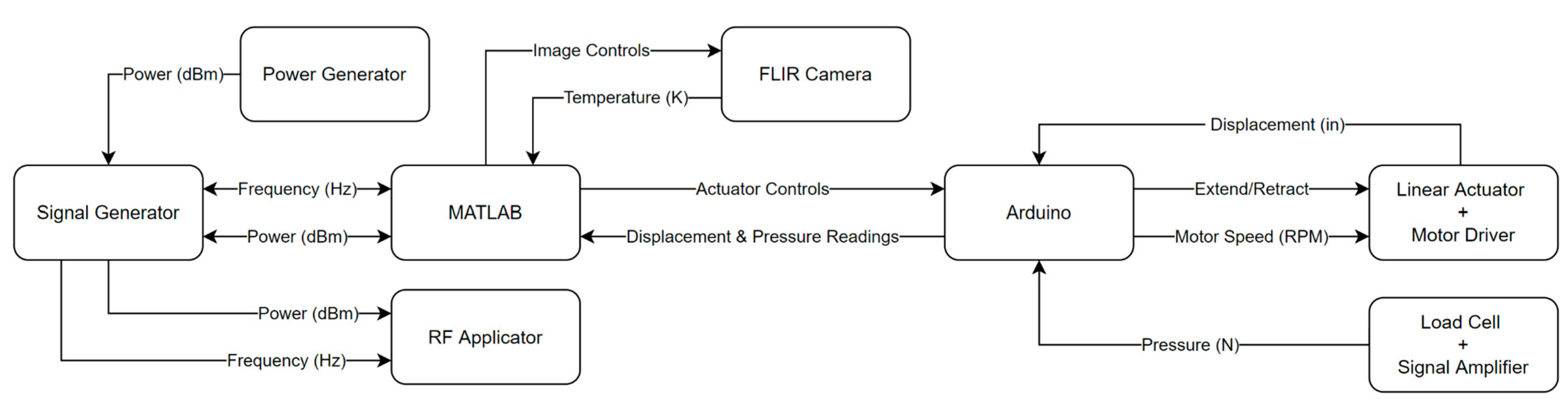
We have developed a closed-loop feedback control system and deployed it for the RF welding machine. The machine consisted of the RF heating system, sensors, loading actuator, and control unit connected to a computer. A target temperature was provided to the MATLAB script that actuates the linear displacement actuator, power, and frequency from the RF signal generator, depending on the sensor data obtained from FLIR thermal camera and the load cell during welding. The control diagram for the system is shown in
Figure 1. FLIR A700 thermal camera and HX711 load cell were used to monitor the thermal profile and load on the actuator. As shown in
Figure 1, the MATLAB control script first collected the data from the sensors and compared these values with the target values for the test. If these target values were not achieved, the MATLAB script went into a loop to achieve these values. For target thermal profiles, the control script increases the RF power level until desired temperatures are reached; the actuator is translated until desired load or displacement is achieved. In this study, we focused on welding 3D-printed coupons made with polylactic acid (PLA). PLA filaments used for 3D printing were purchased from Protopasta (Vancouver, WA). The PLA filament used in printing has a melting temperature range of 195–225 °C, a decomposition temperature of 250 °C, and a relative density of 1.2 g/cc. No special treatment was administered to change the surface finish of the 3D-printed PLA coupons.
Since the bondline is not visible during the welding process and the temperature is measured from the side, a temperature of 105 °C was found through iterative testing to give the best welding results without polymer degradation. A maximum limit of 50 W of RF input power was set for all experiments, and RF frequency was kept constant at 140 MHz.
The machine was programmed to achieve three welding control configurations: hold, displacement, and pressure control. For hold controls, the actuator translates to touch the coupons, and during RF welding, the actuator does not move while ensuring contact and negligible pressure. In displacement control, the actuator starts by holding minimal pressure until the PLA piece reaches 70 °C; this initial temperature is chosen to be close to the glass transition temperature (Tg) of PLA. At Tg, the material transitions from a glassy to a rubbery phase, and the actuator moves to the desired displacement. Displacing in this manner minimizes the pressures early in the process. Finally, pressure control applies pressure prior to any heating; this means that the actuator continues to move until the desired pressure is achieved. The actuator holds this position while the coupons heat up and the substrates get welded.
For all methods, the coupons would heat to the desired maximum temperature of 105 °C. Once the temperature is reached, the signal generator pulses RF power to keep the coupons in the melt temperature range for 60 s. After this time, the piece cools to 70 °C before the actuator retracts, and the weld is considered complete. For this investigation, we examined the effect of three different pressures and displacements applied to the composite bondline.
2.2. RF Heating Elements
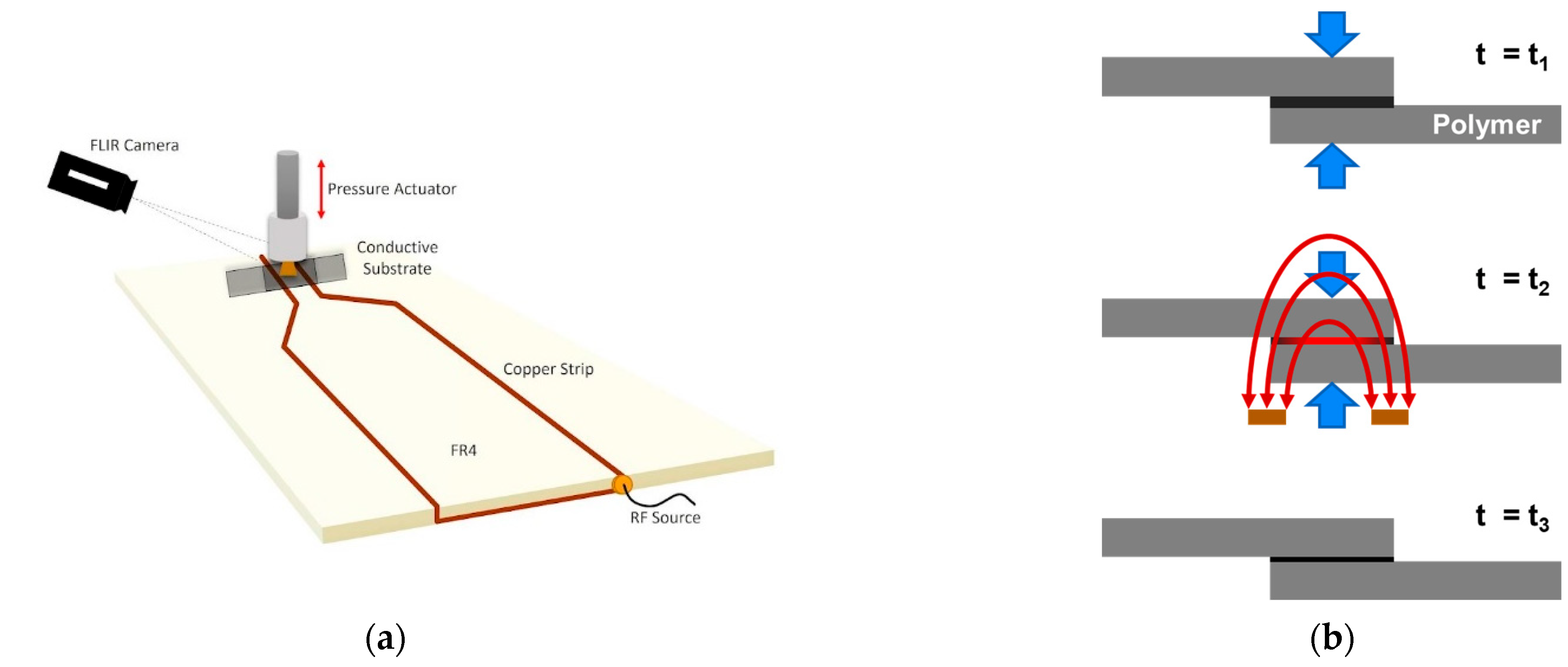
A coplanar RF applicator was used to generate a fringing electric field that extended outwards from the two parallel electrodes, as shown in
Figure 2. The RF applicator was fabricated by laser-etching copper traces on an FR4 substrate. The gap between the applicator electrodes is 4 mm. The RF waves were generated using a RIGOL DSG815 signal generator, amplified using a PRANA GN 500 amplifier, and supplied to the RF applicator using coaxial cables. Temperature changes were monitored using a FLIR A700 thermal camera.
2.3. Graphite-Coated Specimens
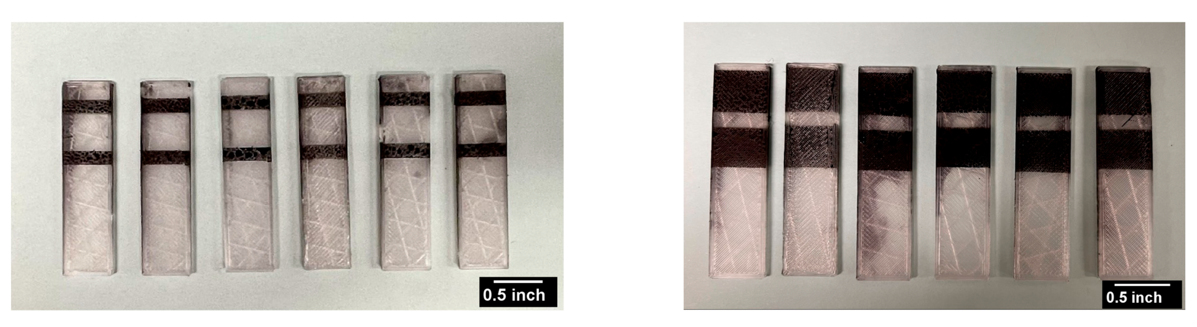
The specimens to be welded were two identical rectangular 3D-printed PLA coupons. A commercially available conductive graphitic ink (SKU-0216) purchased from Bare Conductive was used to pattern the coupons; the ink was diluted to 300 mg/mL in an aqueous medium to optimize the spray process. First, 1 mm-wide single traces with a varying number of layers (1, 3, 5, and 7) were sprayed on the PLA coupon to investigate the RF heating process through the radio-frequency sweep method. 3D-printed PLA coupons were sprayed on using a CZ Robotics CNC Singular Airbrush. Next, an overlap area of 25 × 25 mm
2 was chosen for the welding process; the CNC was set to spray single-layer traces in this area with varying coverage percentages (25%, 50%, and 75%) as shown in
Figure 3. The coverage percentage was modified by changing the width of the sprayed trace within the pre-determined overlap area.
Radio-Frequency Sweep: A radio-frequency sweep was performed to determine the number of layers of sprayed ink that showed maximum RF response, maintaining a single trace across all samples. Due to the system’s frequency-dependent impedance, RF heating rate changes with frequency. The resonant frequency with the largest resistive losses, and thus the maximum heating rate, are identified using a frequency sweep [
28,
29]. When the impedances of the source (RF generator), sample, capacitor, and connecting cables are closely matched at the resonant frequency, power is effectively transferred from the source to the sample. The RF field was applied using a stationary fringing-field applicator, as shown in
Figure 2. The frequency was incrementally changed from 120 to 150 MHz, and the maximum heating rate was noted for each sample.
2.4. Welding Machine Fabrication
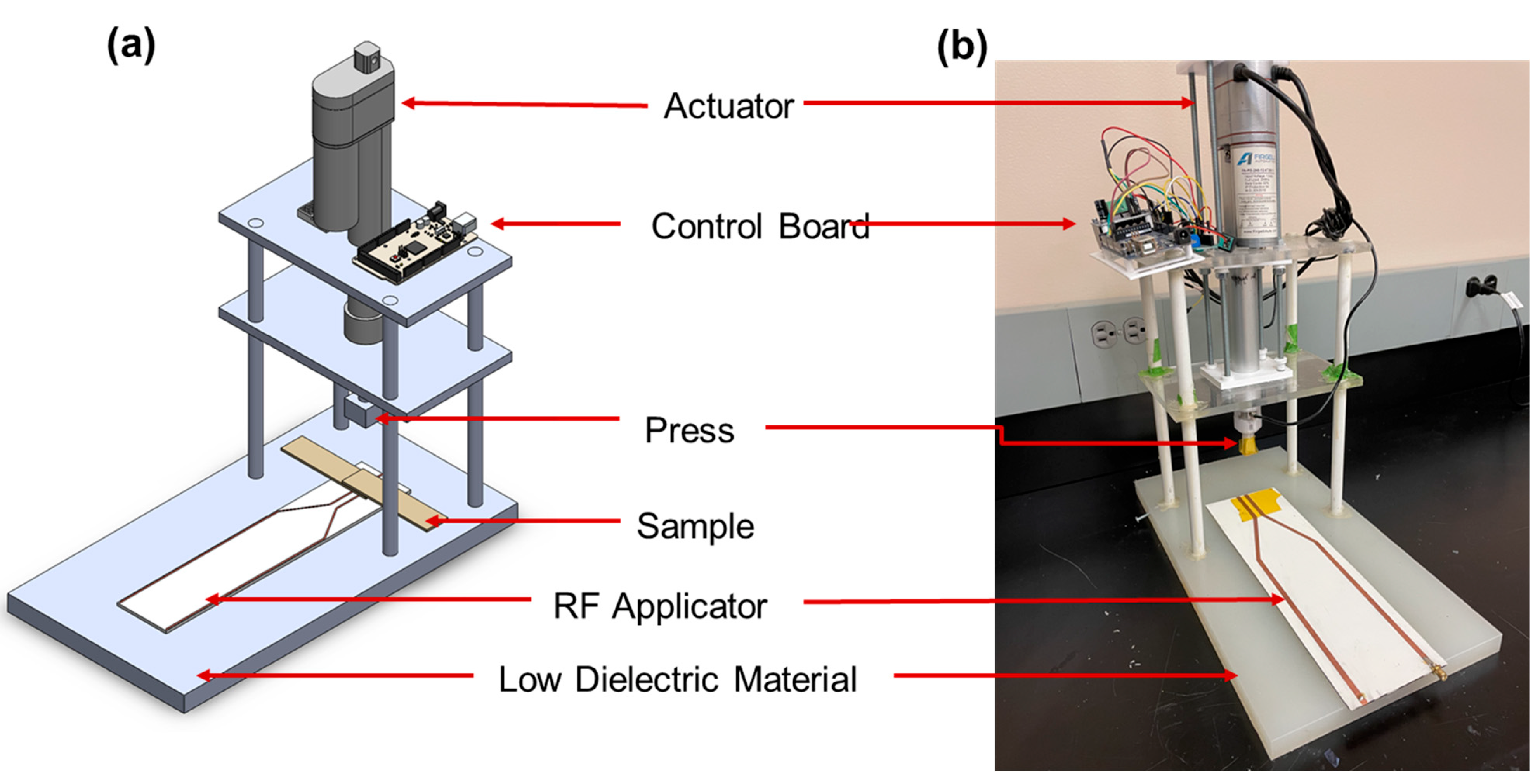
The RF welding machine, seen in
Figure 4, was designed to apply an RF field to a set of coupons while either the pressure or displacement of the coupons was controlled. This novel welding machine emulates the basic principles of plastic welding [
30,
31] using RF energy as the heating source. To achieve this, the machine consists of a low dielectric Teflon base plate attached to fiberglass support rods and acrylic plates. Parts facing the RF applicator can also be lined with aluminum foil to reflect the RF waves if high powers are to be used. A linear actuator is mounted on the acrylic plates, positioned above the RF applicator that rests on the Teflon base plate. The fiberglass supports are attached to the base plate and acrylic mounting plates with epoxy. The linear actuator itself utilizes an attachment head that was 3D-printed from polyethylene terephthalate glycol (PETG). This head has a slot for an HX 711 load cell to read forces applied by the actuator. The force applied by the linear actuator can be set to a specific value applied upon the bond line in the case of pressure control, or it can vary in such a manner that the total displacement at the lap joint is constant in case of displacement control. The load cell was calibrated to describe a relationship between load and output voltage.
2.5. Mechanical Testing
The shear strength in tension of the specimens was measured using an Instron 558H servohydraulic universal testing machine. The lap shear specimens were prepared as per ASTM D 3163-01. The specimens were mounted on a wedge-shaped self-aligning gripper, and a 20 kN load cell was used. The force until fracture was recorded and was divided by the lap area to calculate the shear stress. A representative image of a tested coupon is shown in
Figure S1.
3. Results and Discussion
We have created a polymer welding system along with the hardware and software necessary to create a closed-loop welding process. The machine can operate in three modes: pressure control, displacement control, and holding pressure, depending upon the required weld parameters. The polymer coupons to be welded were sprayed with graphite paint to use RF energy to heat the interface effectively. The machine applies a fringing RF field for targeted heating of the bondline to achieve polymer welding. Note that all these studies were carried out for an optimized graphite coating with desired in-plane conductivity. Anas et al. generalized RF heating patterns for various conductive materials, including carbon nanocomposites and conductive carbonaceous films [
30]. They found that by tailoring the conductivity of nanocomposites, heating rates can be manipulated for fixed power and frequency.
Using the fabricated RF welding machine, we conducted experiments to see the effect of pressure, displacement, and graphite coverage on the bondline on the weld properties.
Figure 5 shows representative graphs for various parameters that were examined. Specimens were described as S
x/P
y/D
z using a nomenclature, where S
x denotes
x% of surface area coverage, P
y represents
y MPa of pressure applied, and D
z is an out-of-plane displacement of
z mm. Therefore, S50/P0.3/D0 is the nomenclature for a coupon with 50% graphite coverage on the bondline, applied pressure of 0.3 MPa, and 0 displacement.
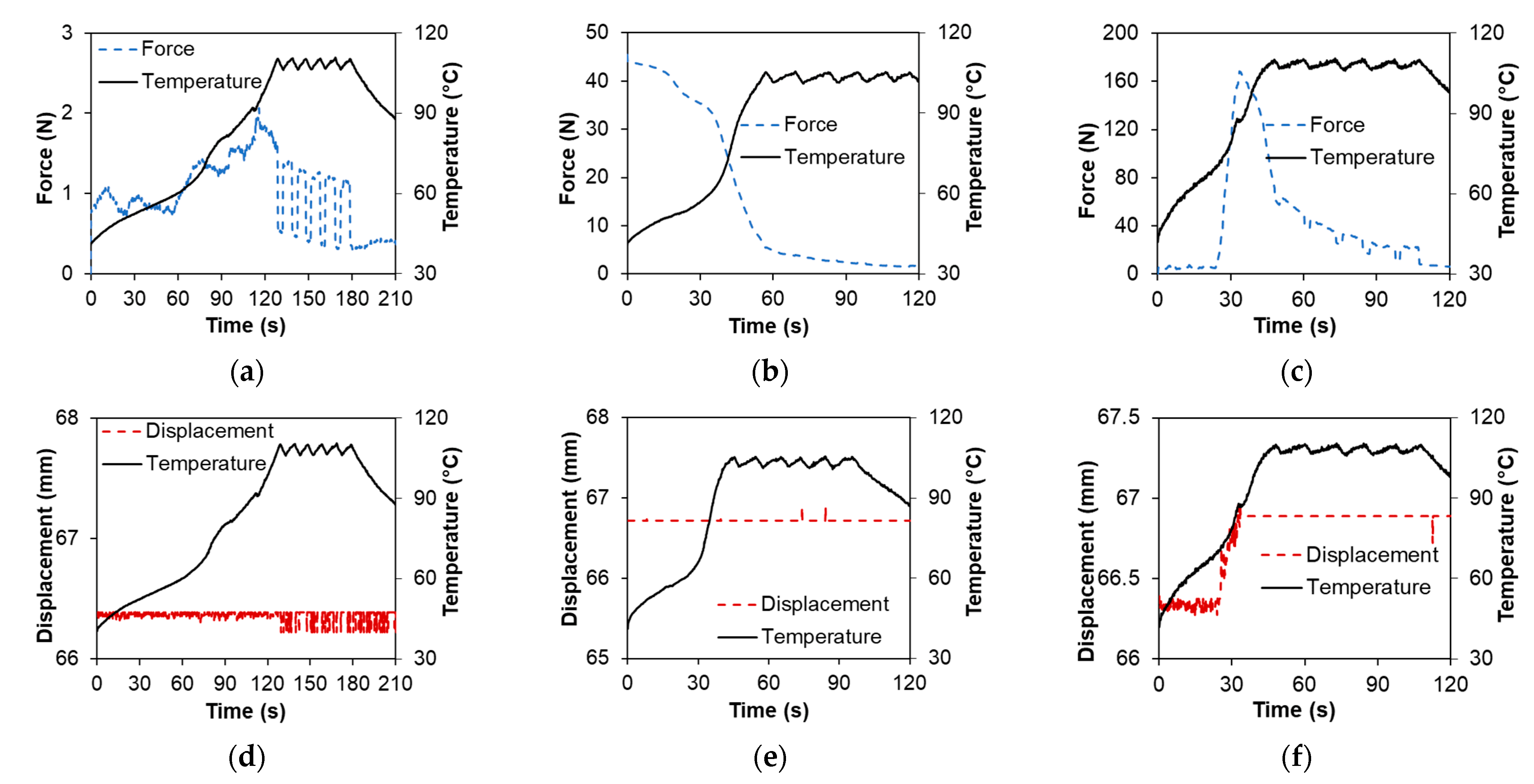
We observed (as shown in
Figure 5) that specimens with 75% graphite coverage take longer to heat than those with 50% coverage. This is because RF energy has to be distributed over a larger volume. As described earlier, the MATLAB controls code switches the RF off once the target melt temperature of 105 °C is achieved, but switches it on when the temperature drops below 100 °C; this results in a triangular oscillating temperature profile (as shown in all sub-plots in
Figure 5—black lines) to maintain the bondline within a specific range without causing sparks or bubbling.
Figure 5a,d shows specimens bonded with hold controls; no change in displacement and minimal fluctuations in the force sensor were observed for these specimens. The fluctuations in the force sensors were within the operating range of error.
Figure 5b,e is a specimen welded in pressure control with a target of 0.3 MPa pressure. The specimen is placed under the actuator, and 0.3 MPa load is applied; then, as RF is switched on, the force drops as the polymer transitions from a solid to a rubbery phase. Finally,
Figure 5c,f is displacement-controlled welding; the displacement increases (by 0.5 mm) as the polymer starts to heat from RF energy, which results in larger forces recorded by the sensor. The displacement is held constant, and the forces drop off once the specimen cools off. After RF welding, displacement of the bondline and the top surface was measured for all the different specimens and compiled in
Figure S2.
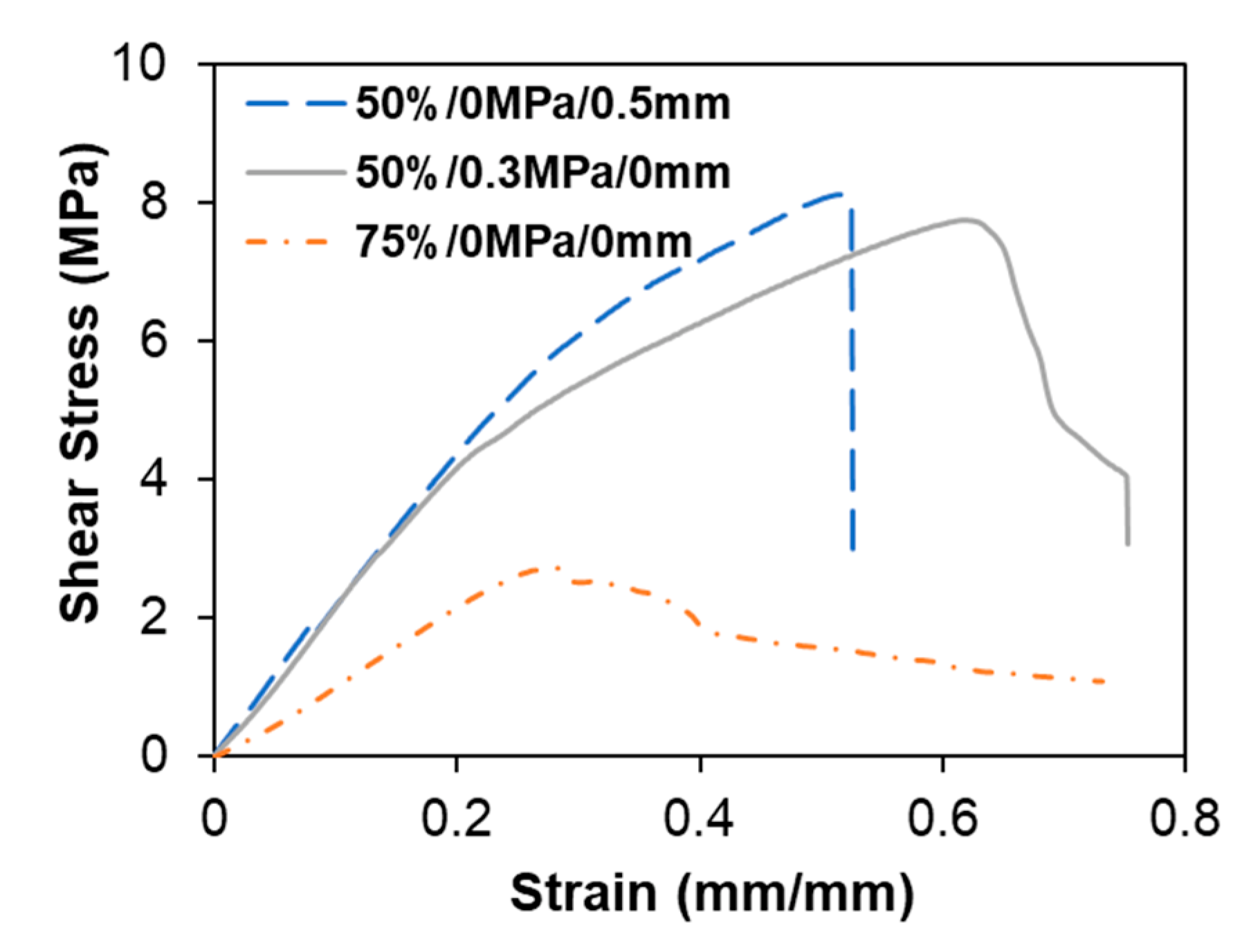
Once welded coupons were retrieved from the machine, these specimens were tested for shear strength. Representative stress–strain curves are shown in
Figure 6. A more detailed analysis of the mechanical testing is discussed in this section.
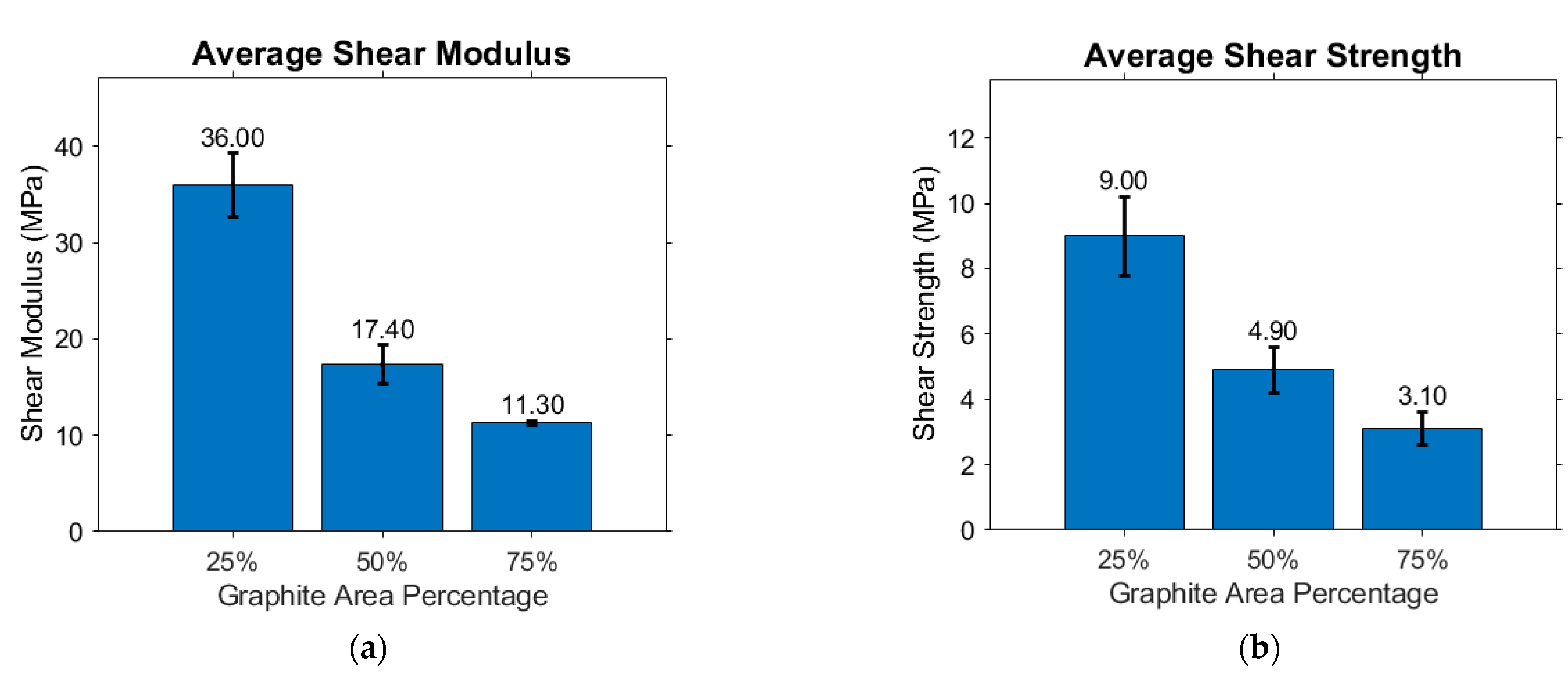
To investigate the effect of graphitic coverage, we examine coupons with 25%, 50%, and 75% coverage. These experiments were carried out in the hold control setting, which maintains a small amount of pressure in order to hold the workpiece without any displacement to mitigate the effects of pressure and displacement on the weld. The resulting shear modulus and shear strengths are shown in
Figure 7. Interestingly, the strength of the welded joint decreases with increases in the graphite area. The average displacement of the bondline and the top surface was similar for all graphite coverages examined in this study, as shown in
Figure S3. This decrease in modulus and strength is driven by two phenomena. Carbon diffusion in the bulk polymer hinders the polymer chain fusion, and graphite acts as a lubricant between the coupons when applying pressure.
Molecular simulations have shown that a graphite film on a polymeric substrate can affect the substrate’s viscoelastic characteristics [
32]. The carbon atoms close to the substrate influence both the melt pool’s long-term (diffusive) motion and the short-term (local mobility) dynamics. Although the local mobility is not significantly affected in-plane with respect to the graphitic material, the graphite atoms affect the out-of-plane mobility of polymers (perpendicular to the bondline). Moreover, the diffusion coefficient of the polymer chains may decrease as the thickness of the carbonaceous (graphite) layer increases. Additionally, we hypothesize that the graphite layer acts as a lubricant since the graphite particles are not functionalized and only have non-bonded interactions with the polymer chains. This behavior also translates to the shear modulus values measured in this study. This self-lubricating property of graphite is used in polymer component applications such as bearings, gears, and water meters [
33].
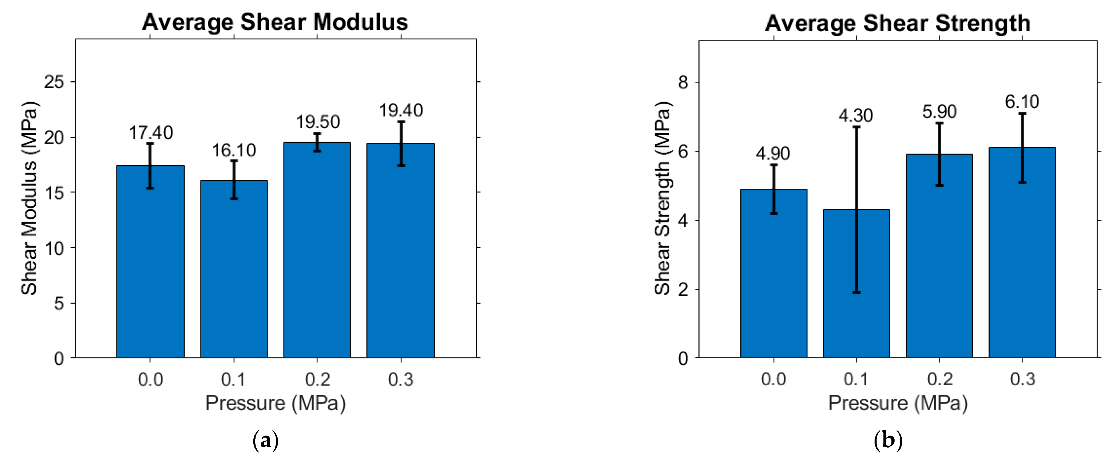
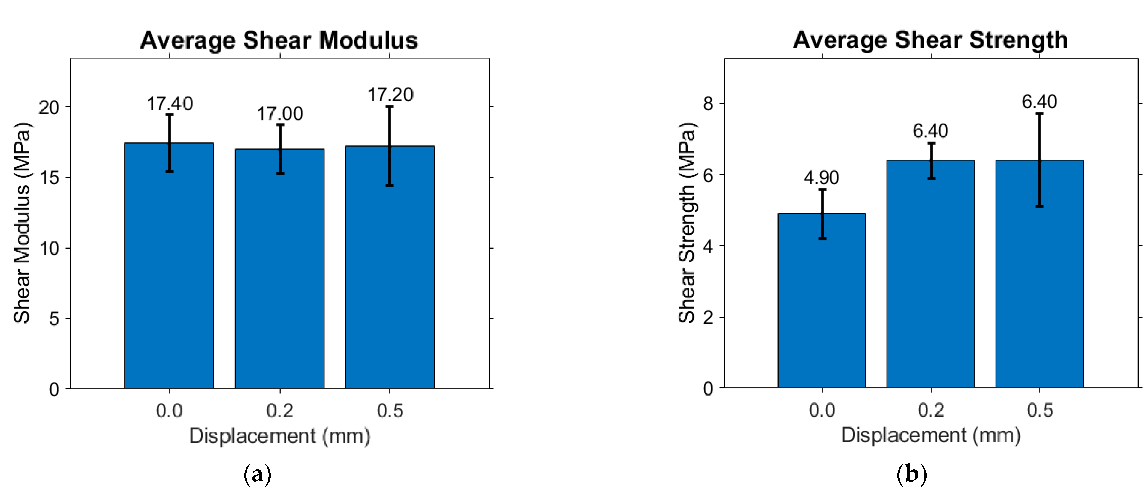
For specimens welded in pressure and displacement control, we focused on 50% coverage area. As seen in
Figure 8, we did not see any significant change in modulus and shear strength for coupons with varying pressures between 0 and 0.3 MPa. For specimens welded in displacement control, we did not see a significant change in modulus, but the shear strength of the specimens increased slightly (
Figure 9). This could be due to better chain diffusion at the bondline, as higher displacement would allow polymer chains from one substrate to intermingle with the chains on the other substrate. The center and top surface displacement of the specimens for pressure and displacement control are shown in
Figures S4 and S5. As expected, the bondline displaces more for specimens tested in displacement control.
We see a slight increase in the shear strength for displacement-controlled specimens as compared to pressure-controlled specimens; this can be explained by examining the force and temperature evolution over time for these experiments. For pressure-controlled specimens, a fixed pressure is attained, and then the actuators are kept at a constant distance during the welding process; for displacement control, the actuator achieves the desired displacement while the bondline heats up. The latter results in better polymer chain diffusion as the polymer interface experiences temperature and pressure (due to displacement) during the process. The latter point can be inferred by examining
Figure 9 and
Figure S5, showing a direct correlation between bondline displacement and lap shear strength of specimens.
4. Conclusions
In this work, we developed an automated closed-loop composite welding machine that uses radio-frequency heating. We focused on welding polylactic acid (PLA) thermoplastic 3D-printed coupons with graphitic susceptors on the bondline to absorb RF energy and dissipate it locally for welding. The setup comprises two sensors—thermal camera and load cell—to measure the temperature and pressure, a linear actuator for controlled displacement, RF heating system, and a controls logic driven by a MATLAB code. These components constitute the closed-looped system that does not require human intervention. The machine can be used in three control settings: hold, displacement, and pressure control. For the polylactic acid (PLA) coupons welded in this work using this machine, we found a good heating response of graphite coatings at the bondline with less than 50 W of RF input powers. Coupons take 50–100 s to heat up to desired temperatures of 105 °C; RF power is then modulated by the controls program to keep the temperature within the 100–105 °C range.
Using the three controls in this closed-loop system, we successfully welded PLA coupons within 2 min. The weld properties of the coupons were evaluated for pressure and displacement control with fixed graphite coverage; the effect of percentage area of the bondline covered by carbonaceous filler was also examined. We found that a higher concentration of graphitic area coverage results in poor polymer diffusion at the bonding interface and lowers the shear modulus and strength. Interestingly, we found that specimens welded using different pressures did not significantly change in mechanical properties, but specimens welded using displacement control saw an increase in shear strength of 31% on increasing the displacement from 0 to 0.5 mm.
The closed-loop RF welding machine employs an out-of-oven, energy-efficient heating method and does not create surface indents, as seen in ultrasonic welding. The closed-loop framework developed in this work has potential applications for automated RF welding, fabrication, and manufacturing for future factories. RF welding machines can be used for welding various thermoplastics, joining thermosets with conductive adhesives, and repairing carbon fiber composites. The processing parameters (input RF power) can be tuned to reach desired heating rates and processing temperatures. We envision that the thermal data generated by the RF welding machine can be stored and used with machine learning algorithms [
34,
35] for more efficient manufacturing in the future.


 ,
, 


