
Improved Fly Ash Based Structural Foam Concrete with Polypropylene Fiber

 ,
,  ,
,  , ,
, ,  and
and 
Abstract
:1. Introduction
2. Materials and Methods
2.1. Materials
2.2. Methods
3. Results
3.1. PC and MC of Samples of FC with Polypropylene Fiber Based on FA
3.2. Durability Characteristics of Foam Concrete with Fly Ash Based Polypropylene Fiber
3.3. Analysis of the Structure of FFC Based on FA
4. Discussion
5. Conclusions
Author Contributions
Funding
Institutional Review Board Statement
Informed Consent Statement
Data Availability Statement
Acknowledgments
Conflicts of Interest
Abbreviations
| CFT | Cycles of Freezing and Thawing |
| CC | Control Composition |
| CS | Compressive Strength |
| DD | Dry Density |
| FA | Fly Ash |
| FC | Foam Concrete |
| FFC | Fiber Foam Concrete |
| FS | Flexural Strength |
| MC | Mechanical Characteristics |
| PC | Physical Characteristics |
| SC | Strength Characteristics |
| TC | Thermal conductivity |
References
- Mydin, M.; Abdullah, M.; Nawi, M.; Yahya, Z.; Sofri, L.; Baltatu, M.; Sandu, A.; Vizureanu, P. Influence of Polyformaldehyde Monofilament Fiber on the Engineering Properties of Foamed Concrete. Materials 2022, 15, 8984. [Google Scholar] [CrossRef]
- Guo, Y.; Xu, C.; Hu, Z.; Wang, L.; Yue, G.; Zheng, S.; Li, Q.; Wang, P. Study on the Performance of Foam Concrete Prepared from Decarburized Fly Ash. Appl. Sci. 2022, 12, 12708. [Google Scholar] [CrossRef]
- Ji, Y.; Sun, Q. The Stabilizing Effect of Carboxymethyl Cellulose on Foamed Concrete. Int. J. Mol. Sci. 2022, 23, 15473. [Google Scholar] [CrossRef]
- Bat-Erdene, P.; Pareek, S. Experimental Study on the Development of Fly Ash Foam Concrete Containing Phase Change Materials (PCMs). Materials 2022, 15, 8428. [Google Scholar] [CrossRef]
- Liu, J.; Ge, T.; Wu, Y.; Chen, R. Effect of Sand-to-Cement Ratio on Mechanical Properties of Foam Concrete. Buildings 2022, 12, 1969. [Google Scholar] [CrossRef]
- Yang, X.; Xu, S.; Zha, Z.; Lv, Y. Strength, Durability, and Microstructure of Foamed Concrete Prepared Using Special Soil and Slag. Sustainability 2022, 14, 14952. [Google Scholar] [CrossRef]
- Xian, G.; Liu, Z.; Wang, Z.; Zhou, X. Study on the Performance and Mechanisms of High-Performance Foamed Concrete. Materials 2022, 15, 7894. [Google Scholar] [CrossRef]
- Beskopylny, A.N.; Stel’makh, S.A.; Shcherban’, E.M.; Mailyan, L.R.; Meskhi, B.; Beskopylny, N.; El’shaeva, D. Influence of the Chemical Activation of Aggregates on the Properties of Lightweight Vibro-Centrifuged Fiber-Reinforced Concrete. J. Compos. Sci. 2022, 6, 273. [Google Scholar] [CrossRef]
- Jiang, Z.; Gao, X.; Feng, X.; Chen, D. Research on the Application of Foamed Lightweight Concrete (FLC) in the Construction of Highway Soft Soil Foundation Engineering with Buried High-Pressure Gas Pipes. Appl. Sci. 2022, 12, 10119. [Google Scholar] [CrossRef]
- Kurpińska, M.; Haustein, E. Experimental Study of the Resistance to Influence of Aggressive Liquids on Lightweight Concrete. Materials 2021, 14, 4185. [Google Scholar] [CrossRef]
- Othman, R.; Jaya, R.; Muthusamy, K.; Sulaiman, M.; Duraisamy, Y.; Abdullah, M.; Przybył, A.; Sochacki, W.; Skrzypczak, T.; Vizureanu, P.; et al. Relation between Density and Compressive Strength of Foamed Concrete. Materials 2021, 14, 2967. [Google Scholar] [CrossRef] [PubMed]
- Zheng, W.; Xiao, X.; Wen, J.; Chang, C.; An, S.; Dong, J. Water-to-Cement Ratio of Magnesium Oxychloride Cement Foam Concrete with Caustic Dolomite Powder. Sustainability 2021, 13, 2429. [Google Scholar] [CrossRef]
- Chen, C.; Li, F.; Jing, P.; Geng, J.; Si, Z. Effect of Pore Structure on Thermal Conductivity and Mechanical Properties of Autoclaved Aerated Concrete. Materials 2020, 14, 339. [Google Scholar] [CrossRef]
- Kadela, M.; Kukiełka, A.; Małek, M. Characteristics of Lightweight Concrete Based on a Synthetic Polymer Foaming Agent. Materials 2020, 13, 4979. [Google Scholar] [CrossRef]
- Amran, M.; Lee, Y.; Vatin, N.; Fediuk, R.; Poi-Ngian, S.; Lee, Y.; Murali, G. Design Efficiency, Characteristics, and Utilization of Reinforced Foamed Concrete: A Review. Crystals 2020, 10, 948. [Google Scholar] [CrossRef]
- Amran, M.; Fediuk, R.; Vatin, N.; Lee, Y.; Murali, G.; Ozbakkaloglu, T.; Klyuev, S.; Alabduljabber, H. Fibre-Reinforced Foamed Concretes: A Review. Materials 2020, 13, 4323. [Google Scholar] [CrossRef]
- Shcherban’, E.M.; Stel’makh, S.A.; Beskopylny, A.; Mailyan, L.R.; Meskhi, B.; Shuyskiy, A.; Beskopylny, N.; Dotsenko, N. Mathematical Modeling and Experimental Substantiation of the Gas Release Process in the Production of Non-Autoclaved Aerated Concrete. Materials 2022, 15, 2642. [Google Scholar] [CrossRef] [PubMed]
- Stel’makh, S.A.; Shcherban’, E.M.; Beskopylny, A.N.; Mailyan, L.R.; Meskhi, B.; Beskopylny, N.; Dotsenko, N.; Kotenko, M. Influence of Recipe Factors on the Structure and Properties of Non-Autoclaved Aerated Concrete of Increased Strength. Appl. Sci. 2022, 12, 6984. [Google Scholar] [CrossRef]
- Zhang, H.; Qi, X.; Ma, C.; Wu, J.; Bi, Y.; Sun, R.; Yu, J.; Xie, D.; Song, J. Effect Analysis of Soil Type and Silt Content on Silt-Based Foamed Concrete with Different Density. Materials 2020, 13, 3866. [Google Scholar] [CrossRef]
- Xu, C.; Han, L.; Tian, M.; Wang, Y.; Jin, Y. Study on Foamed Concrete Used as Gas Isolation Material in the Coal Mine Goaf. Energies 2020, 13, 4377. [Google Scholar] [CrossRef]
- Huang, J.; Tian, G.; Huang, P.; Chen, Z. Flexural Performance of Sisal Fiber Reinforced Foamed Concrete under Static and Fatigue Loading. Materials 2020, 13, 3098. [Google Scholar] [CrossRef]
- Castillo-Lara, J.; Flores-Johnson, E.; Valadez-Gonzalez, A.; Herrera-Franco, P.; Carrillo, J.; Gonzalez-Chi, P.; Li, Q. Mechanical Properties of Natural Fiber Reinforced Foamed Concrete. Materials 2020, 13, 3060. [Google Scholar] [CrossRef] [PubMed]
- Dao, D.; Ly, H.; Vu, H.; Le, T.; Pham, B. Investigation and Optimization of the C-ANN Structure in Predicting the Compressive Strength of Foamed Concrete. Materials 2019, 13, 1072. [Google Scholar] [CrossRef]
- Meskhi, B.; Beskopylny, A.N.; Stel’makh, S.A.; Shcherban’, E.M.; Mailyan, L.R.; Beskopylny, N.; Chernil’nik, A.; El’shaeva, D. Insulation Foam Concrete Nanomodified with Microsilica and Reinforced with Polypropylene Fiber for the Improvement of Characteristics. Polymers 2022, 14, 4401. [Google Scholar] [CrossRef] [PubMed]
- Stel’makh, S.A.; Shcherban’, E.M.; Shuiskii, A.I.; Prokopov, A.Y.; Madatyan, S.M.; Parinov, I.A.; Cherpakov, A.V. Effects of the Geometric Parameters of Mixer on the Mixing Process of Foam Concrete Mixture and Its Energy Efficiency. Appl. Sci. 2020, 10, 8055. [Google Scholar] [CrossRef]
- Beskopylny, A.N.; Stel’makh, S.A.; Shcherban’, E.M.; Mailyan, L.R.; Meskhi, B.; Smolyanichenko, A.S.; Varavka, V.; Beskopylny, N.; Dotsenko, N. Influence of Electromagnetic Activation of Cement Paste and Nano-Modification by Rice Straw Biochar on the Structure and Characteristics of Concrete. J. Compos. Sci. 2022, 6, 268. [Google Scholar] [CrossRef]
- Stel’makh, S.A.; Shcherban, E.M.; Beskopylny, A.; Mailyan, L.R.; Meskhi, B.; Beskopylny, N.; Zherebtsov, Y. Development of High-Tech Self-Compacting Concrete Mixtures Based on Nano-Modifiers of Various Types. Materials 2022, 15, 2739. [Google Scholar] [CrossRef] [PubMed]
- Wang, X.; Liu, L.; Shen, W.; Zhou, H. CFRP Reinforced Foam Concrete Subjected to Dynamic Compression at Medium Strain Rate. Materials 2019, 13, 10. [Google Scholar] [CrossRef]
- Markin, V.; Nerella, V.; Schröfl, C.; Guseynova, G.; Mechtcherine, V. Material Design and Performance Evaluation of Foam Concrete for Digital Fabrication. Materials 2019, 12, 2433. [Google Scholar] [CrossRef] [PubMed]
- Lermen, R.; Favaretto, P.; Silva, R.; Hidalgo, G.; Tubino, R.; Tiecher, F. Effect of Additives, Cement Type, and Foam Amount on the Properties of Foamed Concrete Developed with Civil Construction Waste. Appl. Sci. 2019, 9, 2998. [Google Scholar] [CrossRef] [Green Version]
- Guo, S.; Wang, W.; Jia, Z.; Qi, X.; Zhu, H.; Liu, X. Nanoparticle-stabilized foam with controllable structure for enhanced foamed concrete. Constr. Build. Mater. 2023, 362, 129723. [Google Scholar] [CrossRef]
- Li, S.; Li, H.; Yan, C.; Ding, Y.; Zhang, X.; Zhao, J. Investigating the Mechanical and Durability Characteristics of Fly Ash Foam Concrete. Materials 2022, 15, 6077. [Google Scholar] [CrossRef] [PubMed]
- Gołaszewski, J.; Klemczak, B.; Smolana, A.; Gołaszewska, M.; Cygan, G.; Mankel, C.; Peralta, I.; Röser, F.; Koenders, E. Effect of Foaming Agent, Binder and Density on the Compressive Strength and Thermal Conductivity of Ultra-Light Foam Concrete. Buildings 2022, 12, 1176. [Google Scholar] [CrossRef]
- Li, C.; Li, X.; Guan, D.; Li, S.; Lv, W.; Cong, Z.; Soloveva, V.; Dalerjon, H.; Qin, P.; Liu, X. Study on Influence Factors of Compressive Strength of Low Density Backfill Foamed Concrete Used in Natural Gas Pipeline Tunnel. Sustainability 2022, 14, 8333. [Google Scholar] [CrossRef]
- Li, Z.; Yuan, H.; Gao, F.; Zhang, Y.; Ge, Z.; Wang, K.; Sun, R.; Guan, Y.; Ling, Y.; Jiang, N. A Feasibility Study of Low Cement Content Foamed Concrete Using High Volume of Waste Lime Mud and Fly Ash for Road Embankment. Materials 2021, 15, 86. [Google Scholar] [CrossRef]
- Elrahman, M.; Madawy, M.; Chung, S.; Sikora, P.; Stephan, D. Preparation and Characterization of Ultra-Lightweight Foamed Concrete Incorporating Lightweight Aggregates. Appl. Sci. 2019, 9, 1447. [Google Scholar] [CrossRef]
- Abdullah, M.; Hussin, K.; Bnhussain, M.; Ismail, K.; Yahya, Z.; Razak, R. Fly Ash-based Geopolymer Lightweight Concrete Using Foaming Agent. Int. J. Mol. Sci. 2012, 13, 7186. [Google Scholar] [CrossRef] [PubMed]
- Agustini, N.; Triwiyono, A.; Sulistyo, D.; Suyitno, S. Mechanical Properties and Thermal Conductivity of Fly Ash-Based Geopolymer Foams with Polypropylene Fibers. Appl. Sci. 2021, 11, 4886. [Google Scholar] [CrossRef]
- Su, Z.; Hou, W.; Sun, Z.; Lv, W. Study of In Situ Foamed Fly Ash Geopolymer. Materials 2020, 13, 4059. [Google Scholar] [CrossRef]
- Gökçe, S.; Hatungimana, D.; Ramyar, K. Effect of fly ash and silica fume on hardened properties of foam concrete. Constr. Build. Mater. 2019, 194, 1–11. [Google Scholar] [CrossRef]
- Zhang, S.; Qi, X.; Guo, S.; Zhang, L.; Ren, J. A systematic research on foamed concrete: The effects of foam content, fly ash, slag, silica fume and water-to-binder ratio. Constr. Build. Mater. 2022, 339, 127683. [Google Scholar] [CrossRef]
- Sun, L.; Xu, Y.; Wang, J.; Wang, R.; Yao, L. Designing a superhydrophobic quality and strengthening mechanism for foam concrete. Constr. Build. Mater. 2023, 365, 130073. [Google Scholar] [CrossRef]
- Zhanga, X.; Fenga, X.; Wang, Z.; Jian, J.; Chen, S.; Luo, W.; Zhang, C. Experimental study on the physico-mechanical properties and microstructure of foam concrete mixed with coal gangue. Constr. Build. Mater. 2022, 359, 129428. [Google Scholar] [CrossRef]
- Selija, K.; Gandhi, I. Comprehensive investigation into the effect of the newly developed natural foaming agents and water to solids ratio on foam concrete behavior. J. Build. Eng. 2022, 58, 105042. [Google Scholar] [CrossRef]
- Luhar, I.; Luhar, S. A Comprehensive Review on Fly Ash-Based Geopolymer. J. Compos. Sci. 2022, 6, 219. [Google Scholar] [CrossRef]
- Madan, C.S.; Panchapakesan, K.; Anil Reddy, P.V.; Joanna, P.S.; Rooby, J.; Gurupatham, B.G.A.; Roy, K. Influence on the Flexural Behaviour of High-Volume Fly-Ash-Based Concrete Slab Reinforced with Sustainable Glass-Fibre-Reinforced Polymer Sheets. J. Compos. Sci. 2022, 6, 169. [Google Scholar] [CrossRef]
- Madan, C.S.; Munuswamy, S.; Joanna, P.S.; Gurupatham, B.G.A.; Roy, K. Comparison of the Flexural Behavior of High-Volume Fly Ash Based Concrete Slab Reinforced with GFRP Bars and Steel Bars. J. Compos. Sci. 2022, 6, 157. [Google Scholar] [CrossRef]
- Garg, M.; Azarsa, P.; Gupta, R. Self-Healing Potential and Post-Cracking Tensile Behavior of Polypropylene Fiber-Reinforced Cementitious Composites. J. Compos. Sci. 2021, 5, 122. [Google Scholar] [CrossRef]
- GOST 12730.1-2020. Concretes. Methods of Determination of Density. Available online: https://docs.cntd.ru/document/1200177299 (accessed on 23 December 2022).
- GOST 7076-99. BuIlding Materials and Products. Method of Determination of Steady-State Thermal Conductivity and Thermal Resistance. Available online: https://docs.cntd.ru/document/1200005006 (accessed on 23 December 2022).
- GOST 10180-2012. Concretes. Methods for Strength Determination Using Reference Specimens. Available online: https://docs.cntd.ru/document/1200100908 (accessed on 23 December 2022).
- GOST 25485-2019. Cellular Concretes. General Specifications. Available online: https://docs.cntd.ru/document/1200166675 (accessed on 23 December 2022).
- Beskopylny, A.N.; Stel’makh, S.A.; Shcherban, E.M.; Mailyan, L.R.; Meskhi, B.; Beskopylny, N.; El’shaeva, D.; Kotenko, M. The Investigation of Compacting Cement Systems for Studying the Fundamental Process of Cement Gel Formation. Gels 2022, 8, 530. [Google Scholar] [CrossRef]
- Zhang, D.; Ding, S.; Ma, Y.; Yang, Q. Preparation and Properties of Foam Concrete Incorporating Fly Ash. Materials 2022, 15, 6287. [Google Scholar] [CrossRef]
- Hao, Y.; Yang, G.; Liang, K. Development of fly ash and slag based high-strength alkali-activated foam concrete. Cem. Concr. Compos. 2022, 128, 104447. [Google Scholar] [CrossRef]
- Liu, X.; Ni, C.; Meng, K.; Zhang, L.; Liu, D.; Sun, L. Strengthening mechanism of lightweight cellular concrete filled with fly ash. Constr. Build. Mater. 2020, 251, 118954. [Google Scholar] [CrossRef]


| Material Title | Specific Surface, m2/kg | Normal Density of Cement Paste, % | Grinding Fineness, Sieve Pass No. 008, % | Flexural Strength (FS), MPa | Compressive Strength (CS), MPa |
|---|---|---|---|---|---|
| Portland cement CEM I 42.5N (“Novoroscement”, Novorossiysk, Russia) | 340 | 25 | 98.1 | 4.2 (2 days) 7.7 (28 days) | 26.2 (2 days) 45.3 (28 days) |
| Material Title | Size Modulus | Bulk Density, kg/m3 | True Density, kg/m3 | The Content of Dust and Clay Particles, % | Clay Content in Lumps, % |
|---|---|---|---|---|---|
| Quartz sand (“Arkhipovsky quarry”, Arkhipovskoe, Russia) | 0.81 | 1456 | 2769 | 0.2 | 0.1 |
| Material Title | Fiber Length, mm | Diameter, µm | Density, kg/m3 | Oil |
|---|---|---|---|---|
| Polypropylene fiber (“Fibropolymer”, Moscow, Russia) | 6 | 20–25 | 910 | Silastol CUT 70 |
| Material Title | Density, kg/m3 | Hydrogen Index (pH) of the Foam Generator Agent | Foam Stability, c |
|---|---|---|---|
| Foam generator PB-2000 (Ivkhimprom, Ivanovo, Russia) | 1200 | 8 | 360 |
| Material Title | SiO2, % | SO3, % | TiO2, % | CaO, % | K2O, % | MgO, % | Al2O3, % | Fe2O3, % |
|---|---|---|---|---|---|---|---|---|
| Fly ash (Novocherkasskaya GRES, Novocherkassk, Russia) | 29.78 | 4.13 | 1.09 | 11.56 | 1.43 | 3.42 | 32.98 | 15.61 |
| Defined Characteristic | Formula | Definition |
|---|---|---|
| Dry density (DD) | is DD (kg/m3); m is the mass of the sample (g); V is the sample volume (cm3). | |
| CS | R is CS (MPa); F is breaking force (N); A is the area of the loaded section of the sample (mm2); ∝, δ are scale factors (∝ = 0.95, δ = 0.92 for specimen cross-sectional side 100 mm); Rbt is FS (MPa); a, b, l are width, height of the cross-section of the prism and the distance between the supports, respectively, when testing specimens for tensile bending (mm); is coefficient depending on the moisture content of the samples during the test (Kw = 1.0 for 10% moisture content). | |
| FS | ||
| Frost resistance | is relative decrease in the strength of the main samples (%); is the average value of the strength of the main samples after a given number of test cycles (MPa); is the average value of the strength of control samples (MPa). | |
| is mass loss of the main samples (%); is the average value of the mass of the main samples after water saturation (g); is the average moisture content of control samples in parts of a unit after water saturation; is the average value of the mass of the main samples after passing through the established or intermediate number of freeze and thaw cycles (CFT) (g); is the average moisture content of the main samples in parts of a unit after passing through a specified or intermediate number of CFT. |
| Technological laboratory equipment | Ball planetary mill “Activator-4M” (“Plant of chemical engineering”, Novosibirsk, Russia) |
| Laboratory foam concrete mixer SA 400/500 (DSTU, Rostov-on-Don, Russia) | |
| Test laboratory equipment | Press PM-20MG4 (RNPO RusPribor, St. Petersburg, Russia) |
| Thermal conductivity meter ITP-MG4 (SKB “Stroypribor”, Chelyabinsk, Russia) | |
| Low-Temperature Climatic Chamber NTKK-1.8/4.2 (Research Institute of Building Physics, Moscow, Russia) | |
| Measuring instruments | Microscope MBS-10 (Measuring equipment, Moscow, Russia) |
| Indicator | Change in % DD of FFC Samples with FA Content Instead of Part of Cement (%) | ||||||
|---|---|---|---|---|---|---|---|
| 10 | 20 | 30 | 40 | 50 | 60 | 70 | |
| Dry density | −2 | −6 | −8 | −10 | −5 | −1 | 2 |
| Indicator | % Change in CS of FFC Specimens Containing FA Instead of Part of the Cement (%) | ||||||
|---|---|---|---|---|---|---|---|
| 10 | 20 | 30 | 40 | 50 | 60 | 70 | |
| Compressive strength | 12 | −3 | −9 | −16 | −20 | −32 | −41 |
| Indicator | Change in % of FS of FFC Samples with FA Content (%) | ||||||
|---|---|---|---|---|---|---|---|
| 10 | 20 | 30 | 40 | 50 | 60 | 70 | |
| Tensile strength in bending | 23 | −15 | −28 | −45 | −51 | −53 | −57 |
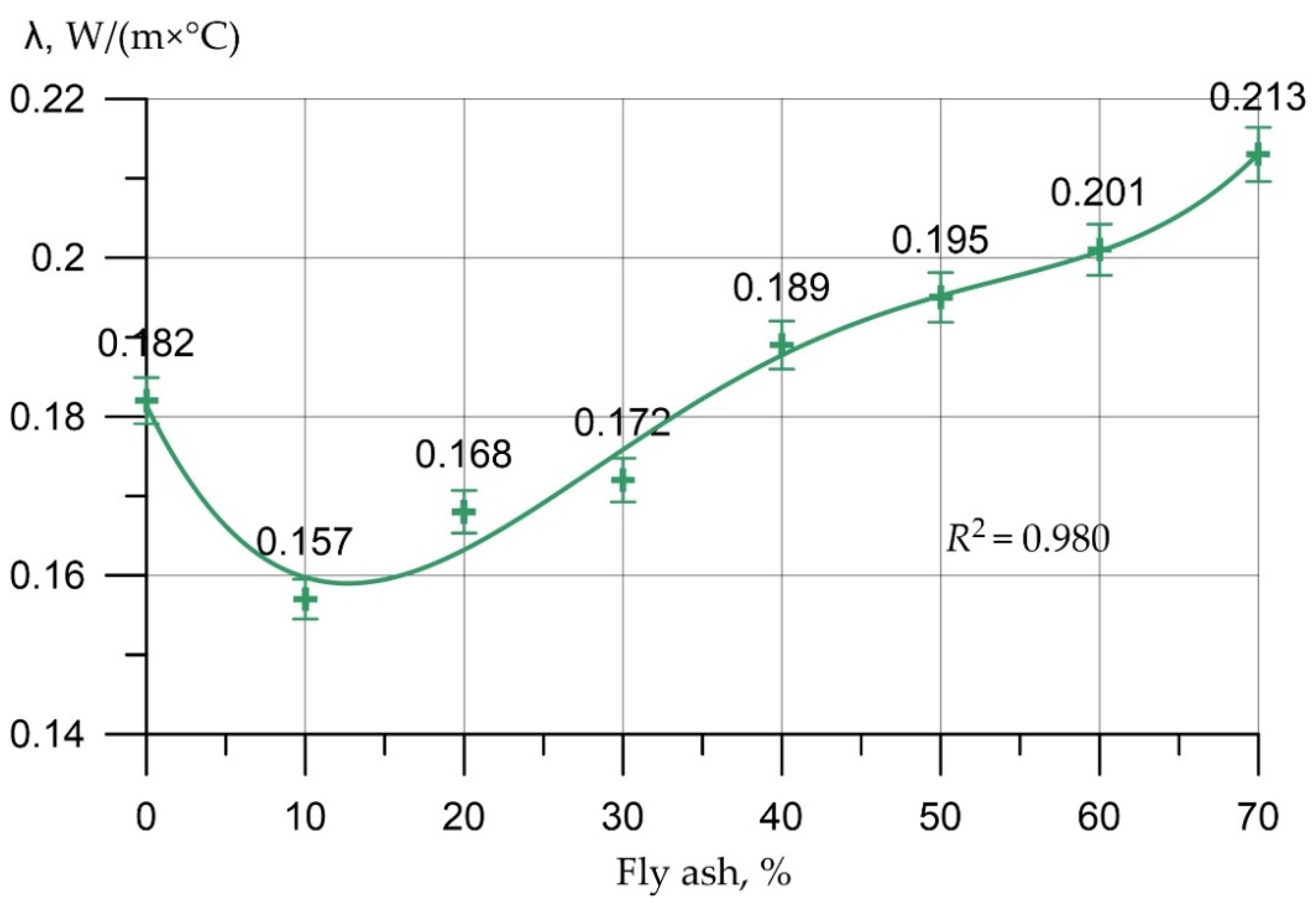
| Indicator | Change in % of TC of FFC Samples with the Content of FA (%) | ||||||
|---|---|---|---|---|---|---|---|
| 10 | 20 | 30 | 40 | 50 | 60 | 70 | |
| Thermal conductivity | −14 | −8 | −5 | 4 | 7 | 10 | 17 |
| Sample Number | CS of FFC Samples of the Control Composition, MPa | CS of FFC with 10% Replacement of Cement for FA, MPa |
|---|---|---|
| 1 | 3.40 | 3.81 |
| 2 | 3.42 | 3.87 |
| 3 | 3.38 | 3.82 |
| 4 | 3.46 | 3.75 |
| 5 | 3.42 | 3.76 |
| 6 | 3.46 | 3.78 |
| Rmtk1 = 3.42 | Rmtn2 = 3.80 |
| Sample Number | CS of FFC Samples of the CC, MPa | CS of FFC Samples with 10% Replacement of Cement for FA, MPa |
|---|---|---|
| 1 | 3.05 | 3.55 |
| 2 | 3.08 | 3.52 |
| 3 | 2.98 | 3.5 |
| 4 | 3.01 | 3.51 |
| 5 | 2.95 | 3.49 |
| 6 | 2.98 | 3.48 |
| 7 | 2.95 | 3.57 |
| 8 | 2.92 | 3.59 |
| 9 | 3.09 | 3.58 |
| 10 | 2.94 | 3.54 |
| 11 | 2.90 | 3.5 |
| 12 | 3.04 | 3.52 |
| Rmtn1 = 2.99 | Rmtn2 = 3.58 |
| Composition Title | Relative Strength Reduction in the Main Specimens, % | Mass Loss of the Main Samples, % |
|---|---|---|
| Fiber foam concrete of control composition | 12 | 4.6 |
| Fiber foam concrete with 10% fly ash instead of cement | 6 | 3.4 |
Disclaimer/Publisher’s Note: The statements, opinions and data contained in all publications are solely those of the individual author(s) and contributor(s) and not of MDPI and/or the editor(s). MDPI and/or the editor(s) disclaim responsibility for any injury to people or property resulting from any ideas, methods, instructions or products referred to in the content. |
© 2023 by the authors. Licensee MDPI, Basel, Switzerland. This article is an open access article distributed under the terms and conditions of the Creative Commons Attribution (CC BY) license (https://creativecommons.org/licenses/by/4.0/).
Share and Cite
Beskopylny, A.N.; Shcherban’, E.M.; Stel’makh, S.A.; Mailyan, L.R.; Meskhi, B.; Varavka, V.; Chernil’nik, A.; Pogrebnyak, A. Improved Fly Ash Based Structural Foam Concrete with Polypropylene Fiber. J. Compos. Sci. 2023, 7, 76. https://doi.org/10.3390/jcs7020076
Beskopylny AN, Shcherban’ EM, Stel’makh SA, Mailyan LR, Meskhi B, Varavka V, Chernil’nik A, Pogrebnyak A. Improved Fly Ash Based Structural Foam Concrete with Polypropylene Fiber. Journal of Composites Science. 2023; 7(2):76. https://doi.org/10.3390/jcs7020076
Chicago/Turabian StyleBeskopylny, Alexey N., Evgenii M. Shcherban’, Sergey A. Stel’makh, Levon R. Mailyan, Besarion Meskhi, Valery Varavka, Andrei Chernil’nik, and Anastasia Pogrebnyak. 2023. "Improved Fly Ash Based Structural Foam Concrete with Polypropylene Fiber" Journal of Composites Science 7, no. 2: 76. https://doi.org/10.3390/jcs7020076