Review

Material Characterization Required for Designing Satellites from Fiber-Reinforced Polymers

by
Esha
and
Joachim Hausmann
*
Leibniz-Institut für Verbundwerkstoffe GmbH, 67663 Kaiserslautern, Germany
*
Author to whom correspondence should be addressed.
J. Compos. Sci. 2023, 7(12), 515; https://doi.org/10.3390/jcs7120515
Submission received: 11 September 2023 / Revised: 6 October 2023 / Accepted: 1 December 2023 / Published: 11 December 2023
(This article belongs to the Special Issue Characterization and Modelling of Composites, Volume III)

Abstract

:
This review paper discusses the effect of polymers, especially thermoplastics, in environments with low earth orbits. Space weather in terms of low earth orbits has been characterized into seven main elements, namely microgravity, residual atmosphere, high vacuum, atomic oxygen, ultraviolet and ionization radiation, solar radiation, and space debris. Each element is discussed extensively. Its effect on polymers and composite materials has also been studied. Quantification of these effects can be evaluated by understanding the mechanisms of material degradation caused by each environmental factor along with its synergetic effect. Hence, the design elements to mitigate the material degradation can be identified. Finally, a cause-and-effect diagram (Ishikawa diagram) is designed to characterize the important design elements required to investigate while choosing a material for a satellite’s structure. This will help the designers to develop experimental methodologies to test the composite material for its suitability against the space environment. Some available testing facilities will be discussed. Some potential polymers will also be suggested for further evaluation.

1. Introduction

Polymer films have been an integral part of satellites since the beginning of the space age. They are used for space applications such as insulation, solar array blankets, and inflatable/deployable structures as a thin film. In the case of thermal insulation, generally, aluminized or silver-coated polymer films are used [1,2,3,4,5,6]. However, using fiber-reinforced polymers (composite material) as primary structures for satellites is still under investigation. Composite materials have been recently used for space applications because of their high specific stiffness and strength. Solar panels, deployable structures, trusses, frames, brackets, support structures, etc., also use composite materials [7,8,9,10,11,12,13]. However, only a few polymers have been used in fiber-reinforced form. For example, in thermoset carbon epoxy and bismaleimide [14,15,16,17,18] and in thermoplastic matrices, only PEEK has been used [7,19,20,21,22,23,24]. The other thermoplastic polymers have not been used yet. It is due to a lack of experimental material data and a lack of understanding of the material behavior under extreme environmental conditions in space.
The major benefit of composite materials is their lighter weight. However, there are several disadvantages. Polymers used as a matrix material for composites are vulnerable to atomic oxygen and ultraviolet rays, which are predominant in the low earth orbit (LEO) environment. Atoms in the molecular chain of the polymer react with atomic oxygen and degrade faster compared to metals. Earlier, in the era of the classic space age (1960–2000), the lifetime of satellites was a couple of decades. Therefore, a durable, high-quality and sustainable material was the main requirement. The issues of money, fuel and mass were not that important in relation to the quality of the satellite. However, now, in the era of the new space age, where the life of the satellite is generally only a couple of years, the requirement for long-lasting material is redundant. The production rate of satellites has increased exponentially with the shift in focus to small satellites [25,26,27,28,29]. Therefore, mass and cost savings are now the major concerns for satellite manufacturers. Small satellites generally de-orbit themselves from their working orbits within a couple of years and dwell in other orbits as space debris [30,31]. In such a case, a long-lasting material in small satellites becomes disadvantageous. Therefore, composite materials could be a good solution because they degrade in space faster and reduce the system mass via surface erosion. In this review paper, the space environment will be characterized, and the effect of the space environment on composite materials will be discussed.
Further subsections will provide a brief introduction to the earth’s atmosphere and its orbits, and a few major characteristics of low earth orbit will be described. In Section 2, the characteristics of the LEO environment and its consequences and effects on the structures of satellites will also be discussed. Material degradation mechanisms and their mitigation method will also be discussed, which will help us understand the properties required for a space-qualified material. This understanding will lead to the definition of a suitable manufacturing process. Section 3 will conclude with the design requirements for space structures, taking into consideration the degradation and its mitigation technique. These requirements are further divided into sub-categories like design, material, mechanical and manufacturing characteristics of polymers or composite materials. Some suitable polymers will also be discussed. The last section will discuss the conclusions and available institutions that provide experimental facilities to research the applications of fiber-reinforced polymers (FRP) in space.

1.1. Brief Introduction to the Earth’s Atmosphere

The Earth’s atmosphere consists of five layers: troposphere, stratosphere, mesosphere, thermosphere and exosphere. The pressure of the atmosphere decreases with altitude. However, temperature varies differently based on the source of heat. The first layer is the troposphere, which ranges from the earth’s surface to 8–15 km. In this layer, the temperature decreases with the height from room temperature to −40 °C. The source of heat to this layer is direct sunlight absorbed from the earth and high-density gases. From 15 to 50 km is the stratosphere where the ozone layers lie, which protects life on Earth from harmful ultraviolet rays of the sun. Below this layer, 99.9% of gas molecules of the atmosphere are present. All aeronautical activities occur below the lower part of the stratosphere. The temperature increases with height. Here, the main source of heat is solar radiation and the heat absorption by ozone molecules. Next, the mesosphere extends from 50 to 85 km. Almost all the harmless meteors and space debris burn up, reaching this layer. Here, the pressure and density of the air are negligible compared to the sea level. Temperature decreases with height, as the only heat source is solar radiation. After the mesosphere, the thermosphere extends until around 600 km [32]. Solar radiation ionizes the gases in the atmosphere from 50 km to 965 km, which overlaps mesosphere and thermosphere. Gases stay in the form of ions rather than in molecules, for example, oxygen, hydrogen, helium ions, etc. Aurora light occurs in this region due to the presence of ions, magnetic storms and solar winds. Satellites are launched in this region of the earth’s atmosphere. After the thermosphere, there is the exosphere, which extends until 10,000 km, and the effect of gravity is the least at this layer. The boundary of space and Earth’s atmosphere is differentiated on the basis of orbital dynamic and aerodynamic forces. The so-called Karman line determines the space boundary as the height of the atmospheric layer, which can be considered as space [33]. At this altitude, the orbital dynamic exceeds aerodynamic forces. The atmospheric layer above 100 km is internationally accepted as a space boundary known as the Karman line [34,35].

1.2. Brief Introduction to the Earth’s Orbits

Space around the Earth has been divided into five main orbits as described by ESA [36].
  • Low Earth orbit (LEO): This orbit is closest to the Earth at an altitude of 160 km (thermosphere) to 1000 km. The International Space Station (ISS) is at 400 km, which is also a part of the thermosphere. The time period of a satellite for one circumnavigation of the earth in this orbit is approximately 90 min. Satellites in this orbit generally perform tasks like telecommunication, science exploration etc.
  • Geostationary orbit (GEO): Satellites in GEO revolve around the earth from west to east above the equator. The time period of the satellite is 24 h—the same as the time period of the earth’s rotation. Due to this reason, these satellites appear fixed at a particular earth position. They perform tasks like telecommunication, weather forecasting, human trafficking, etc. The orbit exists at an altitude of 35,786 km.
  • Medium Earth orbit (MEO): The orbits between LEO and GEO are considered MEO. Satellites in this orbit generally perform tasks like navigation, etc. They are also used for constellations of multiple satellites.
  • Sun-synchronous orbit (SSO): This is a polar orbit where the satellites orbit from north to south poles, and the position of the satellite is synchronous to the sun. The orbiting speed of the satellite is in such a way that the position of the satellite is always fixed relative to the sun. It visits the same location at the same local time. These satellites are used for weather forecasting or monitoring emergencies at a particular position.
  • Geostationary transfer orbit (GTO): These are the orbits used to launch the satellites from one orbit to another orbit. It takes external energy for these maneuvers.
Low earth orbit is actually the part of the earth’s atmosphere with very few air molecules in the form of ions and minimal gravity. The environment of the orbit varies with altitude. Hence, the material degradation phenomenon and design strategies for space structures also vary. Therefore, to select a suitable material for low earth orbit, the LEO environment and its effect on the material must be studied thoroughly. The LEO environment can be categorized into seven sub-categories, according to the NASA researcher guide [37].

2. Effect of LEO Environment on Composite Materials

2.1. High Proximity to the Earth

LEO is the nearest orbit of Earth and a part of the thermosphere, as mentioned earlier. In fact, the gravitational force at the International Space Station ISS is 89% of the force of gravity at sea level [37]. However, the centrifugal force due to orbital velocity balances the forces, creating a feeling of ‘weightlessness.’ The remaining part of the gravity is termed micro-gravity.
Close proximity also has an effect on the orbital lifetime. Microgravity, as well as the effect of residual atmosphere and associated effects, reduce the orbital energy, resulting in de-orbiting. For example, ISS loses its altitude at a rate of 90 m per day. The use of composite materials for satellites in this region is beneficial as they burn out easily in the earth’s atmosphere.
In micro-gravity, the flow of the liquid is dominated more by surface tension rather than gravity. This characteristic can be utilized for the wetting of fibers with resin. In orbit, the manufacturing of composite structures has less porosity due to the uniform wettability of fibers. A woven glass fiber specimen was cured with acrylic-based resin with UV polymer in zero gravity of Novespace’s Zero-G aircraft laboratory. These specimens have 2.5% porosity, whereas the same specimens consolidated in the same condition on Earth have 12% porosity [38]. These specimens have also shown higher failure stress, stiffness and higher failure strain. The curing of resin in microgravity requires less pressure to ensure uniform impregnation, which reduces effort, cost and time. Due to less contamination and voids by the curing process, in-space consolidated material shows better mechanical properties.

2.2. Residual Atmosphere

LEO is still a part of the Earth’s atmosphere. Therefore, it is often referred to as residual atmosphere. The residual atmosphere in LEO consists of molecules of hydrogen, helium, nitrogen and oxygen. At LEO, the residual atmosphere consists of 80% oxygen [39]. Due to the ionizing action of solar radiation, oxygen is in the form of ions, which is hazardous for polymeric composites. The concentration of atomic oxygen depends upon solar activities, which also varies over a period of 11 years. The residual atmosphere and its constituent elements vary with altitude. This is well explained in the handbook of environmental degradation of materials, which describes the distribution of several gases in number density in atom/cm3 over an altitude above 100 km or, in other words, in near-earth space [40]. According to this handbook, at low earth orbit (range 160–1000 km), oxygen shares ~80% of the atmospheric gases. Until 400 km, which is considered a very low earth orbit and a hotspot for launching commercial small satellites, the residual atmosphere is dominated by oxygen and nitrogen, whereas the upper part of LEO orbit (>650 km) is dominated by hydrogen, helium and oxygen [41].
These gas molecules are disassociated in the presence of ultraviolet rays and solar radiation. They stay in as free radical atoms or ions. These ions are traveling in LEO at a speed greater than 7 km/s. Hence, they might be highly reactive to polymeric material, and they oxidize the material, leading to corrosion. Traveling speed increases the rate of hitting ions, which erodes the material. A high rate of hitting speeds up the gradual process of corrosion even further. The surface erosion of the material ultimately creates dimensional instability of the structure. Atomic oxygen also changes the chemical composition of the polymer, which eventually degrades the mechanical strength of the structure.
The ionized gas exhibits a collective response to the magnetic and electric fields of the earth, solar and cosmic radiation. They create a charged field referred to as plasma. Plasma flux modifies the molecular structure of the polymer, resulting in embrittlement. A charged environment alters the optical properties of the thin film polymer or coating used for solar panels, mirrors, antennas, cameras, electronic equipment, etc. Hence, the residual atmosphere at the target orbit requires analysis for the proper selection of the polymer.

2.3. High Vacuum

Even though LEO has a residual atmosphere, there is an ultra-high vacuum, which ranges from 10−9 to 10−11 torr (1.3 × 10⁻⁶ mbar to 13 × 10−9 mbar) [37]. This high vacuum causes the outgassing of volatiles and moisture entrapped in the composite during manufacturing. Reducing the void content is challenging, especially for out-of-autoclave manufacturing techniques. Therefore, highly precise manufacturing is required to produce composite space structures. Otherwise, the gases will escape from the structure in space, which will contaminate other associated components and distort its geometry, which results in inaccuracy in terms of dimension, shape, mass and strength [42,43]. It also deteriorates the absorption and transmittance [44]. Therefore, material that shows low outgassing tendencies is preferred for space applications.

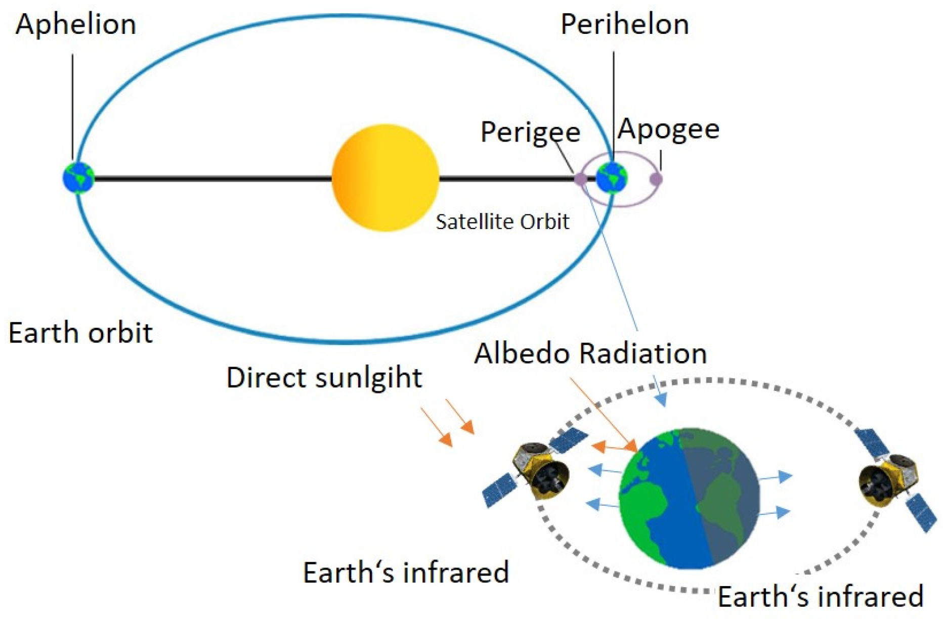
2.4. High Thermal Cycling

As described in Section 1.1, LEO lies in the thermosphere and exosphere of the earth’s atmospheric layers, where the temperature rises with altitude. The temperature of this layer depends on solar radiation, and it can raise the temperature of gases up to 1700 to 2000 °C. This high radiation makes the gas molecules electrically charged. However, gas density is extremely low due to high vacuum. The atmosphere temperature is usually lower than 0 °C. The possible source for heat transfer to objects in LEO is heat transfer from the gas molecules and radiation. Hence, the temperature of the satellite depends upon its position with respect to both the Earth and the sun.
Source of heat for satellites in orbit:
  • Direct sunlight;
  • Reflected sunlight from earth (Albedo);
  • Infrared radiation from Earth;
  • Internal heat produced by satellite component.
Variation of temperature on the satellite surface is due to its position:
  • Its view to the sun, i.e., sun side or shadow side;
  • Position of the earth with respect to the sun, i.e., aphelion or perihelion and position of the satellite with respect to the earth, i.e., perigee and apogee;
  • Its view to the earth, i.e., earth’s shadow or earth-facing.
When the satellite is facing solar radiation directly at the sun’s perihelion and earth’s perigee position, its distance from the sun and earth is minimal, as illustrated in Figure 1 [45]. Hence, the surface of the satellite absorbs the highest amount of heat, whereas, at the sun’s aphelion and earth’s apogee, it absorbs the least. Therefore, the temperature gradient varies from −150 °C to 150 °C within 90 min of its orbital period. Hence, one part of the satellite facing the sun could experience 150° C, whereas another part of the same satellite in the shadow could face −150 °C at the same time. Due to the extreme temperature variation experienced by the same structure, thermal stresses occur. This temperature profile changes every 90 min, which develops thermal fatigue. Fatigue may cause micro-cracks, which reduce the mechanical strength of the material. These cracks, in turn, increase the possibility for atomic oxygen to penetrate inside the structure and erode it. Furthermore, in the presence of these micro-cracks, volatiles and moisture entrapped inside the structure escape easily. Hence, the mass reduces until all volatile components are escaped from the structure [46,47,48,49,50,51,52].
When the structure is made of composite material that consists of fiber and matrix, both have different thermal expansion characteristics. CTE (coefficient of thermal expansion) mismatch, high-temperature variation in the same structure and cyclic thermal loading create high amplitude thermal fatigue. This develops additional micro-damages to the structure. However, this can be minimized by an optimized selection of fiber and polymer matrix. For example, choosing carbon fiber and PEEK polymer creates the overall CTE of the composite in the range of 0 to 8 × 10⁻⁶/°C [20]. The overall CTE of graphite epoxy can also be altered from −0.06 to −2 × 10⁻⁶/°C by changing the fiber layup [24]. Therefore, proper fiber and matrix selection are important to design satellite structures.

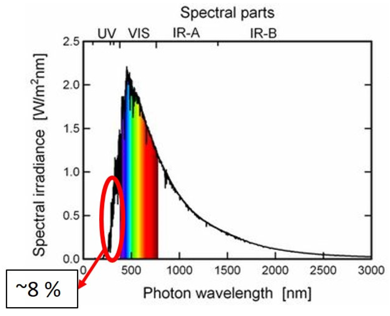
2.5. Ultra-Violet and Ionization Radiation

Sunlight radiates in LEO at its full irradiance due to the absence of the ozone layer. As shown in Figure 2 cited from [53], sunlight radiates energy with wavelengths of 120 nm to 3000 nm. Total solar radiation is about 1366 W/m2, in which the wavelength below 400 nm shares 8% of total radiance [54]. The UV radiation due to solar rays accounts for the wavelength from 40–400 nm, which is further classified between the UVA of wavelengths 315–400 nm, the UVB of whose wavelength is in the range of 280–315 nm and UVC, whose wavelength is in the range 100–280 nm. The energy of the photons is inversely proportional to the wavelength. UVA and UVB contain photon energies greater than 3.9 eV. This energy is sufficient to disassociate the chemical bonds of polymeric chains and produce free radicals [55]. The most significant damage by UV radiation to the composite material occurs in the range of 10–200 nm, which is also referred to as the vacuum UV (VUV) range.
This accounts for 0.1% of total irradiance of UV radiation and 0.007% of total solar radiation [53,56]. The energy of a photon in VUV radiation varies from 6 eV to 124 eV.
UV radiation is also absorbed by the residual atmosphere, which influences the plasma belt, high-energy protons and electrons whose energy can be up to several MeV [37]. Organic compounds are strong UV rays absorbents. It creates photochemical reactions. The thermal energy provided by the radiation breaks the molecular bonds, which eventually alters the molecular structure. These broken bonds can be disassociated from main molecular chains, then re-associate to another polymer chain or can become free radicals [57]. Ultra-violet rays and ionization can affect FRP in the following ways:
  • Material discoloration occurs due to the absorption of UV rays. The surface color of the material gets yellowed or dark. The polymer absorbs UV rays and undergoes several chemical reactions, such as dissociation of bonds, isomerization, free radical polymerization and contamination or recombination with other free radicals. This changes the mechanical properties of the structure.
  • It erodes the surface, which increases the surface roughness. Discoloration, in addition to surface roughness, deteriorates the thermo-optical properties, which decreases the efficiency of the thermal control surface. Hence, low solar absorption and high thermal emittance are required in the material to reduce this phenomenon.
  • The polymeric chain is de- and re-associated. Such cross-linking modifies the chemical structure of the polymer. Such modification leads to loss of mechanical, optical and chemical properties [47,57,58,59,60,61,62,63]. The polymeric chain with aromatic rings or phenyl rings may have higher erosion compared to polymers having long polymeric chains [64]. Aromatic rings or phenyl groups have more C=C bonds, which makes them stronger UV absorbents. Thus, there is a higher chance of chain scissioning and polymer fragmentation.
  • Polymers undergo embrittlement or chain scission in which polymeric bonds de-associate from polymeric chains and perform bonds with free ions. This free radical polymerization creates volatiles, which sublimate in the space. This phenomenon erodes the surface. The presence of a high vacuum increases this erosion even further. Reactive functional groups in the polymer chain sublimate faster in the environment [64].
  • Changes in the chemical structure of the polymer degrades the viscoelastic properties. UV radiation increases the glass transition temperature of epoxy-based shape memory polymer by 2.9% after exposition to UV radiation with a wavelength of 250–400 nm for 80 h [47]. It also increases the stiffness of the material by 41% after 80 hours of exposure. However, 80 h of exposure is too short to conclude the variation of glass transition temperature and stiffness. Hence, more polymers and longer exposure times are required for the investigation.

2.6. Atomic Oxygen

Due to UVC radiation from the sun, the oxygen atoms get disassociated into oxygen ions. These atomic oxygen ions travel in LEO at speeds higher than 7–8 km/s. As described earlier, 80% of the residual atmosphere consists of oxygen at LEO. Atomic oxygen (AO) flux is the most important factor in the degradation of spacecraft materials. The concentration of oxygen atoms at LEO ranges from 108 to 109 atoms/cm3 [65]. However, ISS receives an AO flux of about 5.23 × 10¹³ atoms/cm2/s, whose altitude is 400 km [66]. Atomic oxygen attacking the spacecraft at orbital velocity initiates several material degradation processes. For example, elastic scattering of the oxygen atoms leads to the removal of material through impact load. Kinetic energy possessed by AO at LEO is about 5 eV, which is higher than the bond dissociation energy of polymeric compounds [53,67]. Hence, AO reacts with the polymeric matrix and produces some gaseous oxides like CO2, H2O2, H2O, HCO2, CH3 and other organic compounds, which can be both volatile and non-volatile in nature. Due to huge heat transfers, it directly sublimates, leaving a crater at the surface, which leads to surface erosion [65,66,67,68,69]. Some possible degradation mechanisms that affect the composite material due to atomic oxygen are [1,65,66,67,68,69,70,71]:
  • Change in the chemical composition of the polymer, which leads to loss of mechanical properties;
  • Embrittlement and chain scission of polymeric chains;
  • Material erosion, which leads to loss of material, hence creates dimensional instability;
  • Loss of thermo-optical properties of the material (i.e., absorptance and emittance) due to material discoloration.
Selection of a suitable polymer that has less susceptibility to AO is very necessary in order to design an FRP structure for space [69]. Erosion yield is a criterion to determine suitable polymers.

2.7. Space Debris

Discarded rocket bodies and non-functional satellites dwell in space for many years. Due to collision, these objects are fragmented into even smaller parts, and the number of parts increases even further [72]. There are 34,000 objects larger than 10 cm, 900,000 larger than 1 cm, and 128 million larger than 1 mm floating in LEO orbit with a speed greater than 11 km/s. A total of 26,600 of them have identified objects evolving according to ESA [73]. Each launch introduces two times the amount of debris [74]—once at the start of a mission in the form of a rocket and another at the end of its operational life in the form of defunct satellites. With the emergence of the new space age with small satellites, the number of launches has increased at an exponential rate. In the report from Euroconsult 2020, it is mentioned that 1000 small satellites of mass less than 500 kg (20 satellites/week) have been launched in 2020 despite the coronavirus pandemic [25]. Consequently, in terms of rising object counts, the probability of catastrophic collisions will also grow. Despite the 25-year end-of-life (EOL) guidelines, 90% of satellites weighing 500–1000 kg and 60% of satellites weighing 100–500 kg would fail the 25-year EOL regulation based on an EOL estimation of satellites launched between 2015–2020 [30]. Thus, the low earth orbit is highly polluted with space debris. Seventy percent of space debris belongs to the low earth orbit [73,74,75,76,77,78].
Apart from space debris, there are micro-meteoroids that travel at speeds higher than 11 km/s. They can cause impact damage and sometimes, catastrophic failure if they strike functional satellites. In 2009, one non-functional satellite, Cosmos 2251 (space debris), collided with the functional satellite Iridium 33. This collision has created more than 1500 fragments. These fragments, in turn, increase the growth rate of space debris by 320 objects per year [79,80].
Under such a high impact velocity, the failure mechanism of the composite material transits between ductile to brittle fractures. Due to high impact velocity, there is less time for energy absorption for plastic deformation. This creates severe surface pitting, spalling of coating, cracking and delamination. Impact damage may short out the solar cells and sometimes destroy the functionality of the satellite. High velocity is associated with high kinetic energy, which transits into thermal energy. Hence, the viscoelasticity of the composite material changes due to the temperature rise. Consequently, the polymer softens, which reduces its stiffness. In thermoplastic material, the plastic flow in a softened polymer matrix near the delaminated region reduces the tendency to widen the matrix cracks. This inhibition of matrix cracks reduces the delamination area [81]. However, in thermoset materials, thermal energy reduces the structural integrity. Therefore, thermoplastic composites like PEEK/CF show much less pitting and delamination compared to epoxy/CF [82]. Similarly, the fabricating method also affects the impact damage. Braided composite structures provide more resistance against impact damage compared to unidirectional laminates due to the interlocking of two interlaced fiber bundles. This interlocking provides resistance against crack propagation. The network of interlaced fibers distributes the impact load evenly throughout the structure. This even stress distribution reduces the severity of local damage [83,84,85,86].

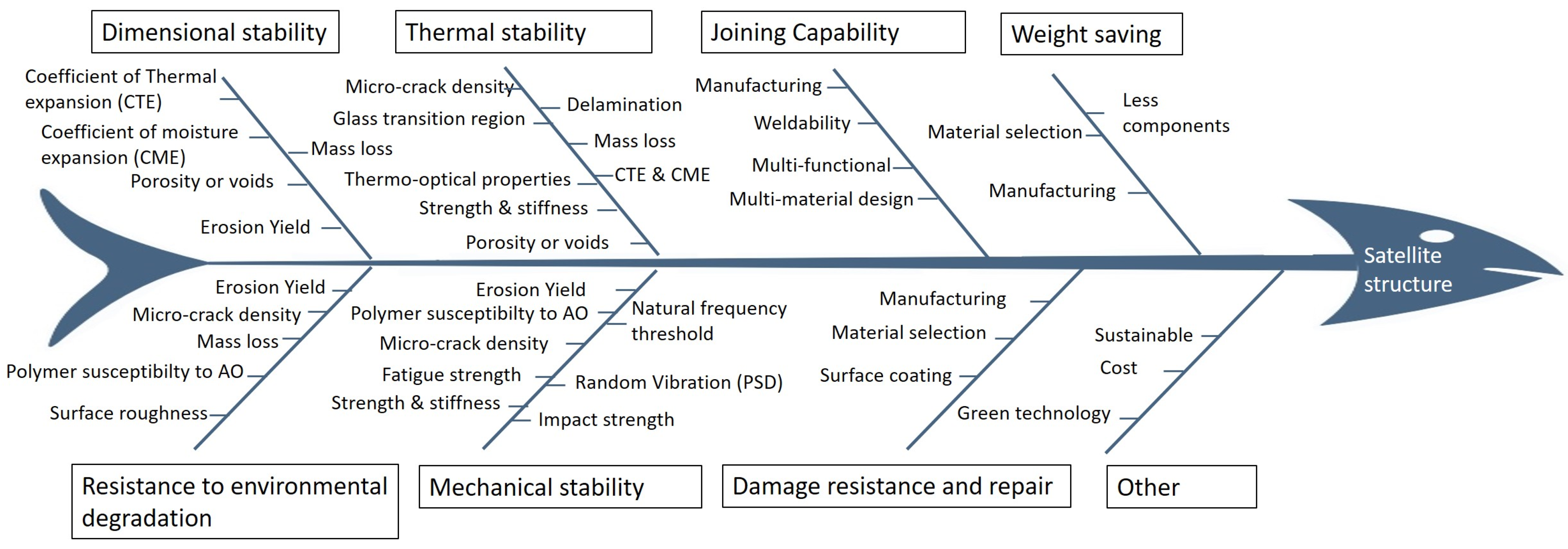
3. Design Requirements for Space Structure

All the features of the LEO act on the satellite structure simultaneously. The material undergoes all different types of material degradation simultaneously. It is necessary to learn about the synergistic effects of all degradation mechanisms. For example, the mass loss due to UV radiation gets saturated after a certain time [47]. However, mass erosion doubles if it is combined with atomic oxygen [87]. Cross-linking and chain scission increases opportunities for atomic oxygen to react. It develops micro-cracks, which eventually increase the permeability of oxygen ions to penetrate the structure. All these effects double the rate of material erosion. Carbon fibers with epoxy and polysulfone matrix have been exposed to the LEO environment for 69 months in the Long Duration Exposure Facility (LDEF) in low earth orbit by the Challenger Shuttle. The mass loss in the epoxy/CF was 20% compared with ground control samples, whereas for polysulfone/CF, it was 3% [88]. The control ground specimens were kept in controlled temperature and humid conditions in the shuttle. They are shielded from exposure to outside space [89]. After studying all the degradation mechanisms caused by each constituent of the space environment, it is clear that the following design requirements are necessary to be evaluated for material selection to design any space structure for low earth orbit.
  • Dimensional stability;
  • Thermal stability;
  • Material resistance to environmental degradation;
  • Mechanical properties;
  • Joining capabilities;
  • Damage resistance and repair capabilities;
  • Weight saving;
  • Resistance to vibration.
Each design requirement needs to be analyzed and quantified with physical characteristics. Some important variables, which can help to evaluate all the above-mentioned design requirements, are explained in a fishbone diagram (Figure 3).

3.1. Design Characteristics of Satellite Structure

There are some common effects of several factors of low earth orbit environment. For example, surface erosion can be caused by UV radiation as well as atomic oxygen. This effect reduces the mechanical and optical performance of the structure. Similarly, mass loss is a common factor in all major space conditions, such as thermal cycles, UV radiation, atomic radiation and vacuum pressure. Figure 3 shows all interconnected design characteristics required to be considered in the design of space structures.

3.1.1. Coefficient of Thermal Expansion

The material expands or contracts when subjected to varying temperatures. This expansion is described by the coefficient of thermal expansion (CTE). Linear CTE is the change in length by the change in temperature:
CTE = Δ l / l Δ T
l is the length of the structure, Δ l is the change in the length, and Δ T is the change in temperature. The unit of CTE is K−1 or °C−1. It is the property of a material that indicates to what extent the material will expand by heating [90].
In fiber composite materials, fiber and matrix have different CTE. Hence, this material develops thermal stresses, even on the microscale, when subjected to thermal loads, which might lead to dimensional instabilities. For example, the CTE of carbon fibers is negative, whereas the polymer matrix generally has pronounced positive CTE [91]. The change in overall CTE is determined by the interfacial bond between fiber and matrix. The effect of thermal cycles on the CTE of composites is a combined effect of fiber and polymer. The CTE of carbon fiber bundles (CFB) increases with thermal cycles first (until 80 cycles) and then gets saturated. This can be attributed to the accumulation of residual strain in the fiber after each thermal cycle [92].
In the case of carbon fiber-reinforced epoxy, the CTE reduces first and then increases when subjected to vacuum thermal cycles. Shin et al. recorded a reduction in both longitudinal and transverse CTE in carbon fiber epoxy with an increase in thermal cycles [93]. Their study was conducted up to 80 thermal cycles. However, Gao et al., who exposed the material to up to 351 thermal cycles, noticed that the longitudinal CTE first decreases and then increases [46]. The initial reduction can be due to loss of matrix and outgassing. Outgassing reduces the size. The more the fiber volume fraction increases (the fiber’s CTE is negative), the more the overall CTE reduces [93]. However, the mass loss does not continue to decrease. It reaches a saturation point after a certain number of thermal cycles [46].
After a certain number of thermal cycles, interfacial de-bonding increases, which is further boosted by micro-cracks induced by the thermal cycles. This relieves the restriction of fiber–matrix interaction, resulting in a decrease in the contribution of the fibers. Consequently, thermal expansion is now gradually influenced by the matrix whose CTE is positive. The density of micro-cracks also increases initially and reaches a plateau value after a certain exposure time [49]. Similarly, the mass loss also attains a saturated value. Therefore, it is crucial to investigate the behavior of CTE for long-duration exposure. Conclusions about CTE behavior based on short-term data would be questionable [46,47,48,49,50,51,52,93]. Currently, the available experimental data for CTE under vacuum thermal cycling is limited to only a few hundred cycles, which is hardly equivalent to half a month in low earth orbit (LEO) environment.
Ten Koh satellite was launched in 2018 to study the variation of CTE of PEEK/CF (polyetheretherketone carbon fiber composite). The satellite monitored in-situ linear expansion and the temperature variation. They reported that the variation of CTE for PEEK/CF in LEO remained unchanged for a short period of time (4 months) because it is within the range of 2–6 ppm/°C [20]. These samples have received actual exposure to the LEO environment, including UV radiation and atomic oxygen. It shows that PEEK composite material is dimensionally stable. The duration of exposure was 4 months, which is the longest among all the research conducted until now regarding material degradation under space exposure. However, the effect of CTE for a long duration of exposure has yet to be examined.

3.1.2. Coefficient of Moisture Expansion

The coefficient of moisture expansion determines the dimensional change in the material due to water or moisture absorption. It quantifies the water-holding capacity of the material. The moisture gets trapped in the composite material on earth. The entrapped moisture in the material will outgas in space, which reduces the dimension. Thus, it affects the dimensional stability of the component. Moisture absorbed in components can affect the satellite in three ways:
  • Water evolves out in space, causing a change in dimension.
  • Water molecules can contaminate other chilled optics or instruments of the satellite.
  • Prediction of the final dimension in the space after desorption of moisture from the structure is very tough and expensive.
Moisture absorption/desorption is calculated by fractional change in mass. It is a measure of a material’s susceptibility to moisture-induced dimensional changes. CME can be calculated through the given formula [94].
C M E = Δ l / l Δ m / m [ % ]
l and m are length and mass, respectively, Δ l is the change in the length and Δ m is the change in mass. Material with less or negligible moisture absorption is preferred for space application. The measurement of the CME is extremely challenging. The swelling/shrinkage of CFRP is in the range < 5 × 10⁻⁵ (wt% H2O)−1 in the fiber direction and 1 × 10⁻³ (wt% H2O)−1 normal to the fiber [18,94]. For space applications, CME should also be measured at different temperature ranges (−150 to 150 °C).
The thermoplastic polymer PEEK shows high tolerance in moisture absorption, i.e., low water absorption compared to the epoxy matrix [7,81]. However, another thermoplastic polymer, like PA is highly sensitive to moisture [18]. Moreover, PEEK does not show any swelling upon absorbing moisture nor reduces its glass transition temperature. Pitch-based carbon fiber with P75/PEEK matrix has 0.1% of absorbed moisture after manufacturing [7]. The manufacturing process also has a great influence on the moisture absorption capacity. For example, honeycomb sandwich structures have a high tendency to entrap moisture [95]. Such entrapped moisture will outgas in space, affecting other satellite components.

3.1.3. Porosity or Voids

Composite materials usually have voids or pores, depending on the manufacturing process. Voids are the regions that are unfilled from polymer and fiber or a small volume filled with air. This occurs mostly due to inaccuracies in the manufacturing process. Voids influence the mechanical properties of the composite, such as interlaminar shear strength, transverse and longitudinal compressive strength, inter-laminar fracture toughness fatigue performance, etc. [96]. In space, voids increase the dimensional and thermal instability of the component as well. Void content is the most common parameter to measure the voids in the fiber-reinforced polymer (FRP) quantitatively. According to ASTM D2734 [97], the void content can be defined as a formula given by:
V v = 100 ρ c m ( W r ρ r + W f ρ f )
W and ρ represent the weight and density of resin (matrix or polymer) by subscript r, fiber by f and composite by c. The densities of polymer or matrix ( ρ r ) and composite ( ρ c m ) can be calculated by standard ASTM D792, which uses the water buoyancy by the Archimedes principle [98] or by ASTM D1505 [99], which uses density gradient technique. The density of fibers can be measured through water buoyancy or a gas pycnometer.
Voids can be filled by moisture, gases, other volatile organic compounds, etc., during the consolidation of the structure. These volatile materials could be any oxides of any organic or inorganic elements. Any solvent, release agent, or degraded or modified polymeric compounds other than the matrix released during curing are also termed volatile. For a space-qualified material, the amount of volatile material must be <0.1% according to the standard ASTM E512 [100]. The void content also indicates the amount of volatiles that can be entrapped [100]. In space, these volatiles escape out due to vacuum pressure, which eventually increases the voids by micro-cracks. Hence, the manufacturing process for fiber-reinforced polymers is an important design parameter.
Void content and its distribution depend upon material properties like the wettability of the fibers by the polymer, volatile components in the polymer itself and processing parameters like temperature, pressure and time [96]. It can also be characterized by the reinforcement structure, stacking sequence and manufacturing process. For example, autoclave curing reduced the void content to <1% [101,102]. In out-of-autoclave processes, the degree of impregnation, polymer rheological properties and its evolution during the process influence the void content. Each manufacturing process has its own controlling parameters that should be carefully addressed to achieve a low void content in the composite material.

3.1.4. Erosion Yield

Erosion yield is a quantitative method to calculate material loss due to atomic oxygen in space. It is defined as volume loss of the structure when one atom of oxygen strikes it in space. It is described as follows:
E y = Δ M S A s ρ s F
E y is the erosion yield of the incident surface against AO flux (cm3/atom), M S is the mass loss of the structure, A s   is the surface area of the structure exposed to atomic oxygen flux (cm2), ρ s   is the density of the material (g/cm3), and F is the fluence of atomic oxygen (atoms/cm2). Erosion yield can be determined by two methods. The first technique is through a comparison of the values of erosion to a space-qualified polyimide film called Kapton film. It is used as a reference material because its erosion yield, fluence of atomic oxygen, and its density are well known [66]. The other technique is to determine erosion yield by recession depth measurement [103].
For composite materials that also contain fibers, the calculation of erosion yield is a little more complex. The erosion yield of fiber composites can be determined as follows [103]:
E y = 1 V f E y f + V m E y m
E y f ,   E y m are the erosion yield of fibers and matrix in the composite, respectively, and V f ,   V m are the volume fractions of fiber and matrix in composite, respectively.
NASA conducted the Polymer Erosion and Contamination Experiment (PEACE) at ISS for 41 different polymers during the Material International Space Station Experiment (MISSE) mission. If the target polymer is not present in that list, then we can also estimate erosion yield by studying the chemical structure of the polymer-repeating unit (monomer) by using a factor called polymer susceptibility to AO, which will be described in detail in the next section. The MISSE mission has calculated erosion yield for polymers (non-reinforced). The erosion yield for composites is calculated with empirical formulas only. The experimental values from space are still required to validate the formulas. However, a few studies have been conducted based on experimental values by simulated space on Earth [1,57,69,70,71,104,105].
Erosion is sensitive to the chemical composition of the polymer. Atomic oxygen reacts with the polymer composite, releasing byproducts that could be both volatiles like CO, CO2, or H2O and non-volatiles like SiO2 or TiO2 [106]. Oxygen atoms are highly reactive due to their bi-radical electronic configuration. However, fluorine and chlorine atoms have higher reactivity compared to oxygen atoms. Therefore, the polymers having pendent fluorine and/or chlorine atoms show lower erosion yield than the reference polymer Kapton film. This pattern is noticed in the recorded erosion yield values of 41 polymers during the MISSE 2 PEACE mission [66]. Based on these values and the chemical behavior of the constituent elements of the polymer, a predictive tool was developed by Banks et al. [70]. This tool predicts the erosion yield due to the atomic erosion of polymers by utilizing the chemical structure, atomic population of the monomer, oxygen bonding information and physical properties. Such tools save the cost and time of in-space testing to calculate the erosion yield of new polymers. Several other researchers also have developed tools to predict the erosion yield based on the susceptibility of oxygen atoms, which will be mentioned in the next section.
The erosion of the polymer is sensitive to atomic oxygen, as well as the impact of UV radiation and thermal cycles. Hence, the solo effect of the atomic oxygen cannot describe the full scenario of mass loss in space. Mass loss of PI Kapton film increases with an increase in AO fluence linearly [104]. The effect of prior exposure to vacuum thermal cycling with UV radiation on mass loss due to the atomic oxygen varies according to the polymers, as well as the coating on the polymer. Kapton film coated with SiOx, AOR Kapton (polyimide film coated with polysiloxane) and Kapton with no primer were subjected to vacuum UV radiation of 1000 ESH (equivalent solar hours) followed by 700 vacuum thermal cycles and finally with atomic oxygen, which is equivalent to LEO. The effect of prior exposure to vacuum thermal cycling combined with UV radiation on mass loss due to atomic oxygen is negligible for SiOx-coated Kapton, whereas the AOR-coated Kapton shows a decreased mass loss. For non-primed Kapton, the mass loss due to atomic oxygen increases if it is priorly exposed to UV radiation and thermal cycling [57]. For unprotected CFRP, atomic oxygen can reduce the mass up to 7% if it is exposed for 8 months of LEO-equivalent exposure. However, the same material with a polymer protective coating reduces between 1–2% of mass under the same amount of exposure. These coatings are cross-linked polystyrene Rexolite, polyethermide ULTEM 1000 and low dielectric constant polymer (LOK) [105].

3.1.5. Polymer Susceptibility to AO

The chemical composition of a polymer is very important when it comes to material erosion due to atomic oxygen. The photo-disassociation energy for the C-C bond is 3.6 eV, while for the C=C bond, it is 6.3 eV. On the other hand, the C-N bond has a photo-disassociation energy of 3.1 eV, and the C-H bond has 4.3 eV [107]. Thus, to break a C=C bond, a higher AO fluence is required than the C-N and C-H bonds. The more the number of C-N bonds in the polymer unit (monomer), the more easily it is eroded by atomic oxygen. To break a C-C bond, the atomic oxygen needs to break the C-H bonds, too. The effect of carbon content in the monomer in estimating erosion yield is quantified by the beta parameter. It indicates that erosion yield is inversely proportional to the number of carbon atoms in a monomer. Cool et al. compared the beta parameter with the erosion yield data of some polymers [69]. It shows a linear relationship with the beta parameter.
However, this linear relationship seems to be valid only for hydrocarbon polymers. The erosion yield of monomers with unsaturated carbon atoms fluorinated or oxygenated polymers deviates from this linear relationship. In Table 1, the erosion yield values obtained by the atomic oxygen beam facility at the University of Toronto and the values obtained by in-space testing from the MISSE 2 mission are compared by their beta parameters. Cool et al. mentioned that it is the strength of the C-C bonds that determines the erosion yield [69]. From Table 1, we can see that even though Teflon (PTFE) and polyethylene have the same beta value, there is a huge difference in their erosion yield values. Hence, it is necessary to investigate other constituent atoms of the monomer, such as nitrogen, fluorine, oxygen, etc., to predict the erosion yield. The beta parameter is not sufficient to predict the erosion yield of the polymer, especially for polymers like PA66, polyethylene, or Teflon (PTFE).
One such investigation was conducted for intermolecular oxygen. Intermolecular oxygen atoms are present in the polymer repeating unit (monomer). It reduces the “effective” number of carbon atoms available for the incoming atomic oxygen. Gokan et al. have studied this relation under oxygen ion beam etching conditions [108]. The presence of oxygen in the monomer as carbonyl group (>C=O) can reduce erosion yield as the bond disassociation energy of the carbonyl group is 7.7 eV, which is even higher than that of C=C bonds. Hence, during disassociation, the intermolecular oxygen atoms in monomers are released as CO, reducing the effective number of carbon atoms in the monomer. This effect of intermolecular oxygen atoms is described by the gamma parameter.
The gamma parameter revises the beta parameter [108]. It is directly proportional to the erosion yield.
E y γ
γ = N t N c N o
E y is the erosion yield in ×10−24 cm3/atom, N t is the number of total atoms in the monomer, N c , N o are the numbers of carbon and oxygen atoms, respectively. Hence, a suitable fiber-reinforced polymer can be evaluated for space application by studying its chemical structure. A few polymers have been studied by Cool et al. using data from the NASA MISSE mission, which are described below in the table [69,108].
The gamma parameter is also an important criterion for the selection of polymers for coating surfaces. The polymer’s chemical composition, structure and the initial conditions of its interaction with atomic oxygen have practical implications for engineering applications by determining the erosion rate. This will help to select a polymer for space applications and develop new surface coatings against erosion. The reaction probabilities obtained from these studies suggest that further investigations on the effects of initial energy exchange during the interaction are a valuable area for research. This research would provide a deeper understanding of the processes underlying the measured erosion yield.

3.1.6. Glass Transition Region of Polymer

The tragic disaster of the space shuttle Challenger in 1986 prompted engineers to investigate the temperature-dependent behavior of polymer in more detail. In this disaster, the rubber O-rings of the booster stopped working as rubber and started behaving as glass. This occurs due to the ambient temperature being below its glass transition temperature [109]. The rubber failed due to a brittle fracture. Later, it was investigated that the temperature exerts an effect on the mechanical properties of the material. A low temperature makes the material more brittle and vice versa. In the case of metals, this difference is minute. However, in the case of polymers, the material changes its behavior from glassy to rubbery with temperature extensively. The chemical composition and molecular motion in polymers determine the glass transition region. As the temperature increases, the mobility of the molecular chains increases, which enhances the rubbery or viscous behavior of the material. Therefore, the stiffness of the polymer in the glass transition region decreases almost linearly with temperature. This range is governed by the temperature rate and applied strain, the frequency of the applied strain, and the chemical composition of the polymer [110,111,112,113]. Dynamic thermo-mechanical analysis (DMTA) is a method to study the polymer stiffness over the temperature range. The specimen is subjected to oscillatory strain under varying temperatures. Therefore, the stress developed in the specimen is dynamic in nature. The dynamic complex modulus of elasticity is calculated based on the response of the specimen. This modulus consists of two parts. One is the storage modulus, which is the real part and represents the elastic behavior of the polymer. The imaginary part of this dynamic modulus represents the dissipated mechanical energy in the form of heat intermolecular deformation or material flow.
In DMTA, the polymer receives both mechanical and thermal energy at a specific frequency. The higher the frequency of the applied strain, the less time available for molecular movement in the polymer. Naresh et al. [111] examined carbon fiber epoxy using DMTA analysis at different frequencies. They observed that the storage modulus of the material had increased by 5.56% when the frequency of the applied strain increased from 1 to 50 Hz, while the glass transition temperature increased by 19.6%. At a high frequency, the time of thermal deformation in the material is lower compared to a lower frequency. Thus, the mechanical properties of polymers depend not only on temperature but also on cycle time. In low Earth orbit, where the temperature fluctuates from −150 °C to 150 °C within the cycle time of 90 min, the study of the glass transition region is extremely important.
The glass transition temperature indicates the temperature range in which the behavior of the material is neither glassy nor viscous. Before this temperature, the material has a high stiffness. Therefore, this parameter is very useful for component designers. There are three types of glass transition temperatures: Tg(E’), Tg(E”) and Tg(tan δ ). Tg(E’) describes the temperature at which the storage modulus (real part of modulus of elasticity) kinks. This indicates the beginning of the glass transition region of the polymer. This is the lowest value among all three. The highest value of the glass transition region is recorded by the curve of tan δ , which represents the ratio of energy dissipation in the form of heat. The glass transition temperature of some polymers used for space applications is listed in Table 2.
The Challenger disaster occurred in the troposphere, where the conditions were quite different from those at LEO. The applied load was huge due to the presence of the atmosphere (aerodynamic loads), launching load, and inertial load. In the orbit, on the other hand, the load acting on the structure is lower due to the absence of atmosphere. Therefore, the effect of the LEO environment on the glass transition temperature of the composite is less relevant. Carbon fiber composites with epoxy and polysulfone matrix were exposed to the LEO environment for 69 months in a long-duration experimental facility (LDEF). The change in glass transition temperature was negligible in both cases compared to the ground specimens subjected to thermal cycling only [88]. Similar behavior was observed for epoxy shape-memory-polymer/CF under the exposure of sole atomic oxygen equivalent to 1.2 LEO months [118]. Thermoplastic polymers, especially crystalline polymers, also show changes in glass transition temperature [22,119]. Polymer films of polystyrene, polyvinyl toluene and polymethylmethacrylate did not show any difference in Tg after 5.8 years of space environment exposure in LDEF [118].

3.1.7. Mirco-Crack Density

Micro-cracks in composites are inter-laminar or intra-laminar and generally grow transverse or parallel to the fibers. Micro-cracks can be characterized by crack density and crack length. The micro-crack density is determined by dividing the number of micro-cracks on the surface of the specimen by its surface area. When the specimen is subjected to thermal cycling, the number of micro-cracks increases with the number of thermal cycles until a saturation point [48,49]. A honeycomb sandwich with CFRP sheet was subjected to thermal cycling (range −185 °C to 150 °C) to study the growth of micro-cracks. The number of micro-cracks level off after 30 thermal cycles. These cracks are major delamination cracks. In laminates, the micro-crack density increases with stiffness and longitudinal CTE of the fibers when it is subjected to cryogenic thermal cycling. These cracks are major transverse cracks. However, the number of these micro-cracks levels off after a couple of thermal cycles [120]. Although the number of transverse micro-cracks levels off after a few thermal cycles and remains constant for a while, if the specimen is exposed to thousands of thermal cycles from a few cycles, the number of transverse micro-cracks will increase linearly, breaking that plateau region. In a study by Shimokawa et al. [52], a carbon fiber-reinforced thermoplastic (polyimide/CF) and a thermoset laminate (bismaleimide/CF) underwent normal lab-conditioned thermal cycles (−54 °C to 177 °C) with 10,000 and 1000 cycles respectively. Micro-cracks in polyimide/CF initially level off at <500 cycles, then increase significantly. The possible reason could be isothermal aging at dwelling time at each high and low temperature. Another reason could be an accumulation of thermal residual stresses, which release itself in the form of micro-cracks.
With regards to the LEO environment, vacuum thermal cycling along with irradiation would increase the micro-cracking significantly. Here, the outgassing of volatiles, erosion effect of atomic oxygen and matrix degradation add their contribution to the growth of micro-cracks, too. Therefore, quantitative analysis of micro-cracks development due to thermal cycling over a long period of time is required.
Modification of the polymer can also reduce the formation of the micro-cracking. For example, a self-healing composite contains a separate agent in the polymer, which seals the micro-cracks retarding its propagation. Such inclusion of a separate agent in the polymer is similar to the healing of cracks. Self-healing composites can also be considered for the design of space structures [121,122].

3.1.8. Damage Resistance and Repair

Damage resistance is an important characteristic in the design of a space structure due to the possibility of extreme high-energy impact damage by space debris or meteoroids. Matrix cracks and inter-ply delamination are predominant near the impact point. The shear strength of the material provides resistance against matrix cracking and delamination among plies. Thermoplastic polymer composites like PEEK/AS4 show 20% higher shear strength than graphite epoxy subjected to an impact load of 3200 lb for 0.003 s [82]. Self-healing polymers can also provide higher resistance to impact damage with the help of micro-encapsulation. The healing agent is encapsulated in the matrix, which ruptures at micro-cracks. This agent fills the crack and starts polymerization through the healing agent and a catalyst [123,124,125]. The use of such polymers in space suits can enhance their protective capabilities, particularly against potential cuts and punctures caused by micrometeoroids and orbital debris (MMOD). They have the potential to prevent depressurization, a critical and potentially fatal concern during extended crewed missions. However, a comprehensive analysis of the long-term degradation of these polymers is necessary to understand their performance in the space environment, especially concerning radiation effects.

3.1.9. Strength and Stiffness

The strength and stiffness of the material vary according to the change in the environment to which it is exposed. Varying temperatures accompanied by irradiation reduce the strength of the material. The stiffness of the epoxy composite material decreases after AO and UV radiation [87,119]. However, radiation shows minimal effect on the microstructure of semi-crystalline polymers compared to epoxy. In addition, the degree of crystallinity does not change with irradiation of semi-crystalline polymers. However, thermal cycling affects the strength of the material due to the formation of micro-cracks [119]. The presence of atomic oxygen and ultraviolet rays leads to premature failure of the structure if it is subjected to primary loading. Ply orientation or fiber angle also plays an important role in the mechanical properties of the samples exposed to atomic oxygen. The reduction in flexural properties is not significant in the case of unidirectional 0° laminate because the load is carried by the 0° fibers from the eroded part of the specimen [89]. Woven fabric also shows insignificant changes in flexural modulus in the 0° and 90° direction, but for angle ply stacking [0°, ±45°, 0° ± 45°]s, its values drop significantly when exposed to direct AO exposure. This is due to erosion or loss of the 0° plies, which are more responsible for load-carrying capacity.
In MISSE 6, a few samples of thin film polymers were investigated under stressed conditions. The samples are strained while exposed to the wake and ram side of the ISS. The stressed Kapton samples at the ram side (the side of the space station that receives more atomic oxygen and solar radiation) were completely broken, while there was only some evidence of cracking in the samples of the wake side. The applied stress was 6% of the ultimate strength. These samples were initially stretched in the range of 0.005–0.7% strain. This shows that the samples on the ram side failed before the yield strength. This premature failure of the material was due to atomic oxygen [126].
Six commercially available composite materials were subject to 500 thermal cycles in the range of −153 °C to 93 °C and electron radiation. These materials are; one amorphous, two semi-crystalline thermoplastics and three different epoxy-based thermosets. The thermal cycling of irradiated specimens of thermoset epoxy material degrades their stiffness significantly. However, semi-crystalline PPS/CF shows a slight decrease in strength, whereas semi-crystalline PEEK/CF shows a significant loss of strength, whereas the amorphous thermoplastic P1700/C6000 shows a reduction in strength [119]. However, 500 thermal cycles are very few to develop a concrete conclusion about the behaviors of thermoplastic composites as they account for only one month’s equivalent LEO exposure. Longer exposure to such an environment is required to draw a conclusion about the strength.

3.1.10. Random Vibration

During the launch of satellites, the material is subjected to strong random vibration. The vibrational frequency of a typical mission for the launch of CubeSat is around 50–90 Hz [127]. However, random vibration can be as high as 2000 Hz. Therefore, power spectral density (PSD) of acceleration analysis is performed to analyze the stability of the structure under high vibrational loads. The PSD is a measure of the area of the domain of acceleration amplitude within a particular frequency range. Eigen frequencies of the structure are analyzed in modal analysis. The quasi-static analysis is also conducted to analyze the material for high inertial loads acting on the satellite during launch. A sine burst test is also performed to evaluate the strength of the structure over a vibration table, which induces acceleration with a loading factor equal to the launching scenarios [128].

3.1.11. Manufacturing Method

Some of the design characteristics can be controlled by selecting the proper manufacturing process. For example, void and porosity can be controlled by the right selection of consolidation temperature and pressure. Consolidation in an autoclave creates fewer voids than out-of-autoclave consolidation. Similarly, filament winding, pultrusion, tape laying, braiding, resin transfer molding, and vacuum-assisted resin transfer molding can be analyzed comparatively in regard to void formation [24,96,101,129]. The method of fiber and resin placement can influence the growth of micro-cracks. Mehdikhani et al. [96] explained void formation according to its consolidation process. They also explained manufacturing parameters, which can control the formation of voids.
Braided composites show higher resistance to micro-cracking compared to filament winding. Braided composite structures have interlocking adhesion between two yarns that counteract the propagation of micro-cracks. The braided fabric improves energy absorption, which increases robustness under impact loads. In a burst pressure test, braided hydrogen pressure vessels create a leaky hole that releases the pressure before catastrophic vessel rupture. Therefore, these structures mitigate the catastrophic failure compared to filament winding. In interwoven tapes, there is inter-laminar adhesion that prevents micro-cracking and ultimately reduces permeation [83,84]. In a study by NASA, woven fabric and cross-ply laminate were exposed to 500 thermal cycles of temperature, 129 °C to 94 °C [130]. It was found that the woven fabric of epoxy graphite exhibited 3 cracks/inch while a cross-ply laminate exhibited 11 cracks/inch. The CTE of a cross-ply laminate decreases by 20% after 500 thermal cycles, whereas the plain weave epoxy graphite shows no change in CTE. Hence, woven fabric is more resistant to thermal expansion than cross-ply laminate [130]. Due to a lack of technological advancement in the fabrication process, the void content in braided parts was about 8% during the 20th century [24]. High void content reduces the performance of the fabricated parts and tends to absorb high amounts of volatiles, which results in outgassing. However, according to the current state of the art, the void content of thermoplastic composite structures with braiding technology with an out-of-autoclave consolidation process is below 1% [96,129,131,132,133,134]. In addition, out-of-autoclave consolidation processing makes the fabrication process faster and cheaper.
For thermoplastic materials, the fabrication cycle time, post-machinability, weldability and thermoformability are better than that of thermosets. It saves on costs and production time. Current technology advances in polymer processing, i.e., out-of-autoclave manufacturing such as pultrusion, tape placement, thermoforming, resin transfer molding, etc., can also produce high-quality products with minimal porosity. The challenge for out-of-autoclave processes to produce space structures is to produce low-void materials (void/porosity < 1%). Each process has different parameters to control the void content. In resin transfer molding, the voids can be controlled by optimizing capillary number, injection pressure and vacuum level. In automated thermoset lay-ups, the properties of prepreg, such as void content, its surface roughness and compaction pressure and temperature during curing, are important, whereas in automated thermoplastic lay-ups, in adition of void content, level of crystallinity, fiber volume fraction and dimensional tolerance, the force & contact time of the compaction rollers are the decisive factor to control the void content [96,129,133,134,135].
In the next ten years, demand for satellites will be high. Therefore, rapid manufacturing methods will be needed. Additive manufacturing and out-of-autoclave manufacturing processes are suitable to meet this demand. Additive manufacturing is also a popular manufacturing method for developing the primary structures of spacecraft. 3D printing has speed up the manufacturing of satellites, especially cube satellites in the range of 100 to 1000 kg. CRP Technologies, an additive manufacturing company, has produced several satellite parts by selective laser sintering of Windform material, which is carbon fiber or glass fiber-reinforced polyamide. These parts are used as deployers for the antenna, frames of lens sensor assemblies and battery housing [136]. The main advantage of additive manufacturing is the freedom from manufacturing constraints when designing a part with monolithic structural elements. With 3D printing, critical subsystems can be printed together with high packing density and minimum joints.

4. Testing Facilities Available

In this section, some testing facilities that provide space-related material tests are suggested. The type of tests required to verify the material for space applications can be divided into aerospace and space environment tests.
In aerospace, the forces and degradation mechanisms during launch are more dominated by vibration, aerodynamic forces, and heat. Therefore, the characterization tests will be modal analysis, quasi-static analysis and random vibration analysis [127,137]. Resonance frequency tests and power spectral density (PSD) analysis can be performed in this campaign [127]. NASA’s Wallops flight facility provides launch-related testing that focuses on the vibration, strength, and outgassing properties of composite structures. For vibration campaign test set-ups, the Hellenic aerospace industry can be approached [127]. The tests required to qualify the launch loads will not be discussed further in this paper.
In the space environment, there are three main elements in regard to composite material: vacuum thermal cycling, solar and high ultra-violet radiation and atomic oxygen flux. The University of Patras, Rio Campus, offers thermal vacuum testing with −40 °C to 60 °C thermal cycles at a vacuum pressure of 10−1 mbar. The CubeSat UPsat, which was a part of the EU-funded QB50 project, was tested at this facility [127].
At the Korean Advanced Institute of Science and Technology (KAIST), a LEO environmental test facility can be used to study the degradation of composite materials. It can expose samples to a high vacuum of 2 × 10⁻⁶ mbar, UV radiation (less than 200 nm wavelength), thermal cycling of −70 °C to 100 °C and AO with a flow rate of 9.08 × 10¹⁴ atoms/cm2s [138].
A plasma asher can also be used for atomic oxygen exposure. This device releases oxygen ions at a frequency of 13.56 MHz RF in a vacuum of 1–2000 mtorr (0.001–2 mbar), which is a little low compared to the LEO condition [139]. This machine can produce an energy of 0.1 eV, which is also a little low compared to the energy associated with the ions in LEO. Nevertheless, this is one of the cheapest solutions to provide rough estimations of the material degradation due to atomic oxygen.
ESA ESTEC (European Space Research Technology Center) has a ground-based AO flux facility, which can generate ions with an energy of 5.5 eV and an AO flux of 1025 atoms/cm2s. It produces atomic oxygen by dissociation of molecular O2 using a pulsed CO2 laser. The background pressure is below 10−5 mbar [140,141]. NASA Marshall Space Center provides an atomic oxygen beam facility, a UV radiation test chamber, and a combined environmental effect testing chamber [142].
DLR (German Aerospace Center) has a solar simulation facility with a complex irradiation facility and high vacuum. Material degradation can be studied individually by space exposure through vacuum thermal cycling or solar radiation. However, synergetic exposure is not possible until now [63].
The University of Toronto also provides an atomic oxygen beam facility whose results are being used to develop several prediction models for erosion yield due to atomic oxygen [1,64,69,70]. The facility is capable of delivering neutral ground atoms at ~2.2 eV with a flux level of ~1016 atoms/cm2s−1 [143].

5. Few Suggested Composite Materials

The high strength-to-weight ratio, joining capability (specifically thermoplastics) and thermal stability have motivated numerous researchers to use composite materials for space applications since 1960. Fiber-reinforced epoxy was used in large sunshades, antennas, fairings and payload adapters, skin modules, sandwich panels and other primary structures of the satellite during the last decade of the 20th century. Due to a lack of technological progress in various manufacturing techniques, thermoplastic material is still rarely used for space applications. Moreover, there is a lack of experimental data to describe the material behavior in space environment. Especially in the case of fiber-reinforced plastics, two matrix materials have been studied well until now, namely PEEK and epoxy. Other studies were conducted on polymer thin films only.
PEEK is one of the most resistant polymers against AO and absorbs 10 times less moisture compared to epoxy. Semi-crystalline PEEK has a 17% weight-saving capability in the fabrication of a sunshade compared to epoxy [7]. The joining capability of thermoplastic materials by welding makes it more suitable compared to epoxy resin. Several investigations have been conducted on the behavior of PEEK polymer in the LEO environment.
Polymers like PET or PI (Kapton) also show good resistance against AO, similar to PEEK. PET film is generally used together with aluminum metallization as a sail membrane or multi-layer insulation [144,145]. The erosion yield due to atomic oxygen for PET and PEEK is similar, as well as its moisture absorption [2]. PET shows high resistance against impact loads and chemical reactions. It is used for space suits [146]. However, the manufacturability of carbon fiber composites with PET matrix is challenging.
Cross-linked ethylene-tetrafluoroethylene (X-ETFE) is widely used for jacketing the material for space applications, particularly for electric cables on solar arrays. It exhibits high resistance to heat, cold flow and creep resistance. The operating temperature can be as high as 150 °C [147].
Windform material is a 3D printed material composed of carbon-fiber-reinforced polyamide manufactured by selective laser sintering technology. It does not show remarkable damage under vacuum ultra-violet radiation of wavelength range 115–200 nm and exposure for 36 continuous hours [148]. This material has qualified for the ESA requirements of outgassing [149]. This material is now available for space application. A nanosatellite TuPOD was constructed by Windform XT 2.0 CRP in 2016. Another satellite, PrintSat, also uses a primary structure made of Windform XT material [150]. However, this satellite became lost, and its position is unknown to date. The exposure time of 36 h was very short compared to the estimated dwelling time of the satellite or satellite parts in space, which should be at least more than a year. Long-term material degradation analysis is required.
Accura Bluestone stereolithographically fabricated parts from nano-composite material are developed by 3D systems. These parts were recently used for spacecraft structures, particularly miniature satellites. It was developed for 3D printing and is generally used for nozzles, tubing and storage cold gas propulsion systems, and attitude thrusters. This plastic has a high stiffness and impact strength as well as extreme resistance to high temperature due to its monolithic element structure [150,151,152].
Florinated-ethylene Teflon film (FEP) is already used for multi-layer insulation. It is highly resistant to erosion from atomic oxygen and ultraviolet rays. Due to its chemical structure, it is 15 times more resistant than PEEK [Table 1]. Therefore, fiber-reinforced FEP would be a good candidate material to investigate.
Polytetrafluoroethylene (PTFE) is also highly resistant to atomic oxygen, 21 times more resistant than PEEK (Table 1). PTFE is already used in satellites (e.g., Grossamer deorbiter) as plates, cable insulation, and coatings. The strength of PTFE decreases significantly when exposed to radiation. However, by reinforcing PTFE with fibers, its strength can be improved. Fiber-reinforced PTFE could be a good candidate for studying material degradation [21,153].
Other polymers suggested for material investigation are bismaleimides (BMI), polyimide, phenolic, polyetherimide, polystyrene, polysulfone, polystyrene, PMMA Teflon etc.

6. Conclusions

Several degradation mechanisms due to the space environment for composite materials were studied in this paper. The effects of each component of the LEO environment were studied, and a few major design characteristics were drafted, which should be investigated by a space engineer to develop a composite space structure. One such characteristic was an empirical model based on the chemical composition of the polymer to estimate the potential erosion due to atomic oxygen. The performance of the polymer can also be evaluated to some extent by these models [57,69,70,71,104,105]. However, to verify these models, we require experimental data, which we lack. Apart from the selection of a proper polymer and fiber, it is also necessary to select a proper manufacturing method. By studying the degradation mechanisms and the techniques to mitigate the degradation, the selection of the material can be done wisely.
Even though polymers have been used since the beginning of the space age as polymer thin films in protective layers, coating, insulation, space suits, etc., we have limited material data. Since 2000, the new space age industries have focused more on reducing weight. They have already listed the benefits of composite structures in space. Nowadays, composite materials are used in space structures such as antennas, hinges, morphing wings, booms, solar arrays, struts and trusses, frames of satellites, battery casings, holding cases of satellite equipment like lenses, sensors, thrusters, reaction wheels, cameras, etc.
Surprisingly, these composite parts are launched into space without a thorough examination of material data dependent on the space environmental conditions. Space regulations for cube satellites are also relaxed compared to those for large satellites. One possible reason behind this could be a lack of assessment of the risk factors that could lead to catastrophic failures of the satellites. Material erosion and degradation due to long-term exposure are not well understood, and there is a lack of data on material performance in relation to space environmental factors.
Studying material degradation in the space environment has many challenges. The initial challenge is to develop testing chambers equivalent to the orbit environment, which can replicate approximately vacuum, radiation and thermal cycles experienced in the orbit. Very few institutions have these facilities, but they are mostly in separate chambers situated in different locations. The costs and time required to obtain experimental data from these specialized chambers are significant, which further extends project durations and costs. Synergetic climatic chambers that combine multiple environmental factors could be a valuable addition, which not only reduces the time but also improves the accuracy of material data, as a synergetic environment is more detrimental to material degradation. However, it is a second challenge to combine all the factors of the orbit environment in one chamber, even with modern technology. The third challenge is to accelerate the process so that long-term material data could be generated in the shortest time period and at the lowest cost.
The synergistic effects of the LEO environment, including electron/proton and ultraviolet radiation combined with atomic oxygen and thermal cycling, can significantly accelerate mass erosion compared to individual factors. For example, the double-sided aluminized Kapton thermal blanket used in the ISS was completely damaged after one year of exposure even though the expected lifetime was 15 years, based on ground laboratory tests in which the specimen was irradiated by atomic oxygen with fluence level equivalent to 15 years [68,71]. The erosion rate of Kapton film in space (in orbit of the ISS) was 18 times higher than the results obtained in a ground test facility on Earth [2]. Therefore, the simulation of individual effects in test facilities cannot accurately estimate the synergetic damage rates.
This study concludes that in the era of the new space age, where the satellite production is as high as 20 satellites per week [27] and satellite life is short, the use of composite materials is beneficial. It degrades faster and hence can sublimate in space rather than dwelling in the space for a long time. Therefore, material degradation should be investigated thoroughly for more polymer and composite materials. A comprehensive material database should be provided to the designers to create a responsible space structure that will not fail during the functional life of the satellite as well as does not stay longer in space as space debris.

Author Contributions

Esha: Conceptualization, data collection, methodology, investigation, writing—review and editing, and visualization; J.H.: writing—review and editing, and supervision. All authors have read and agreed to the published version of the manuscript.

Funding

This research received no external funding.

Conflicts of Interest

The authors declare no conflict of interest.

References

  1. Devapal, D.; Packirisamy, S.; Korulla, R.M.; Ninan, K.N. Atomic oxygen resistant coating from poly(tetramethyldisilylene-co-styrene). J. Appl. Polym. Sci. 2004, 94, 2368–2375. [Google Scholar] [CrossRef]
  2. de Groh, K.K.; Banks, B.A.; Miller, K.R.S.; Jaworske, D.A.; Dever, J.A.; Sechkar, E.A.; Panko, S.R. NASA Glenn Research Center’s Materials International Space Station Experiments (MISSE 1–7). In Proceedings of the International Symposium on SM/MPAC and SEED Experiments, Tsukuba, Japan, 10–11 March 2008; p. 46. [Google Scholar]
  3. Son, G.; Kim, C.-G. Protective effect of nanocomposite film from the low earth orbit environment. J. Compos. Mater. 2015, 49, 2297–2306. [Google Scholar] [CrossRef]
  4. Gordo, P.; Frederico, T.; Melicio, R.; Duzellier, S.; Amorim, A. System for space materials evaluation in LEO environment. Adv. Space Res. 2020, 66, 307–320. [Google Scholar] [CrossRef]
  5. Gouzman, I.; Girshevitz, O.; Grossman, E.; Eliaz, N.; Sukenik, C.N. Thin Film Oxide Barrier Layers: Protection of Kapton from Space Environment by Liquid Phase Deposition of Titanium Oxide. ACS Appl. Mater. Interfaces 2010, 2, 1835–1843. [Google Scholar] [CrossRef]
  6. Kawasaki, H.; Okazaki, S.; Murakami, M. Temperature Dependence of Thermal Performance of Space Using Multilayer Insulation. In Proceedings of the 42nd International Conference on Environmental Systems, San Diego, CA, USA, 15–19 July 2012; American Institute of Aeronautics and Astronautics: Reston, VA, USA, 2012; Volume AIAA 2012-3407, p. 10. [Google Scholar]
  7. Garvey, R.E. Potential for Advanced Thermoplastic Composites in Space Systems; Oak Ridge National Laboratory: Oak Ridge, TN, USA, 1990; p. 17. [Google Scholar]
  8. Leipold, M.; Eiden, M.; Garner, C.E.; Herbeck, L.; Kassing, D.; Niederstadt, T.; Krüger, T.; Pagel, G.; Rezazad, M.; Rozemeijer, H.; et al. Solar sail technology development and demonstration. Acta Astronaut. 2003, 52, 317–326. [Google Scholar] [CrossRef]
  9. Chandra, A.; Wilburn, G.; Thangavelautham, J. Advanced inflatable de-orbit solutions for derelict satellites and orbital debris. arXiv 2019, 9. [Google Scholar] [CrossRef]
  10. Santoni, F.; Piergentili, F.; Donati, S.; Perelli, M.; Negri, A.; Marino, M. An innovative deployable solar panel system for Cubesats. Acta Astronaut. 2014, 95, 210–217. [Google Scholar] [CrossRef]
  11. Wen, L.Z.Z.Y.; Kan, M.Q.Y.Y.Z. Cubesat Brake Sail De-Orbit Device. CN105799956A, 12 December 2018. [Google Scholar]
  12. Harkness, P.; McRobb, M.; Lützkendorf, P.; Milligan, R.; Feeney, A.; Clark, C. Development status of AEOLDOS—A deorbit module for small satellites. Adv. Space Res. 2014, 54, 82–91. [Google Scholar] [CrossRef]
  13. Mason, C.; Tilton, G.; Vazirani, N.; Spinazola, J.; Guglielmo, D.; Robinson, S.; Bevilacqua, R.; Samuel, J. Origami-Based Drag Sail for Cubesat Propellant-Free Maneuvering. In Proceedings of the 5th Nano-Satellite Symposium, Troy, NY, USA, 22 November 2013. [Google Scholar]
  14. Mazzio, V.; Bixler, C. Optimized design and fabrication processes for advanced composite spacecraft structures. In Proceedings of the 17th Aerospace Sciences Meeting, New Orleans, LA, USA, 15–17 January 1979; American Institute of Aeronautics and Astronautics: Reston, VA, USA, 1979. [Google Scholar]
  15. Mayer, N.J. Carbon composite in space vehicle structures. In Proceedings of the International Conference on Carbon Fibres, Their Place in Modern Technology, London, UK, 18–20 February 1974; Volume 39. [Google Scholar]
  16. Jamison, R.D.; Griffin, O.H.; Ecker, J.A.; Skullney, W.E. Use of Graphite/Epoxy Composite in Spacecraft Structures: A Case Study. Johns Hopkins APL Tech. Dig. 1986, 7, 290–294. [Google Scholar]
  17. Sandvik, K. Development of Composite and Polymer Material CubeSat Structure with Focus on Materials; Norwegian University of Science and Technology: Trondheim, Norway, 2012; TMM 4501 Specialization report; p. 90. [Google Scholar]
  18. European Cooperation for Space Standardization. Space Engineering, Structural Material Handbook—Part 1; ESA Requirements and Standards Division: Noordwijk, The Netherlands, 2011; Volume 1. [Google Scholar]
  19. Ampatzoglou, A.G. Design, Analysis and Optimization of a Micro-Satellite for the Study of Lower Thermosphere and Re-Entry Conditions. Ph.D Thesis, University of Patras, Patras, Greece, 2017. [Google Scholar]
  20. Abdullah, F.; Okuyama, K.; Tapia, I.F. In-Situ Monitoring of Carbon Fiber/Polyether Ether Ketone (CF/PEEK) Composite Thermal Expansion in Low Earth Orbit. In Proceedings of the 8th International Symposium on Space Technology and Science, Tokyo, Japan, 17–21 June 2019. [Google Scholar]
  21. Fernandez, J.M.; Schenk, M.; Prassinos, G.; Lappas, V.J.; Erb, S.O. Deployment mechanisms of a Gossamer satellite deorbiter. In Proceedings of the ESMATS 2013, Noordwijk, The Netherlands, 25–27 September 2013; Volume 15, p. 8. [Google Scholar]
  22. Young, P.R.; Slemp, W.S. The performance of selected polymeric materials exposed to low earth orbit. Polym. Adv. Technol. 1998, 9, 20–23. [Google Scholar] [CrossRef]
  23. Czechowicz, A.; Razaei, F.; Bach, A.; Schummer, F.; Zhu, Z.; Langer, M. New Space New Manufacturing—Injection Molding of Satellite Structures. In Proceedings of the 2021 IEEE Aerospace Conference (50100), Big Sky, MT, USA, 6–13 March 2021; IEEE: Piscataway, NJ, USA, 2021; pp. 1–11. [Google Scholar]
  24. Lukez, R. The Use of Graphite/Epoxy Composite Structures in Space Applications; DigitalCommons@USU: Logan, UT, USA, 1987; p. 11. [Google Scholar]
  25. EuroConsult. Prospects for Small Satellite Market Forecasts to 2029; EuroConsult: Washington, DC, USA, 2020; p. 7. [Google Scholar]
  26. EuroConsult. Prospects for the Small Satellite Market Forecasts to 2028; EuroConsult: Washington, DC, USA, 2019. [Google Scholar]
  27. EuroConsult. A Satellites to Be Built & Launched by 2028; EuroConsult: Washington, DC, USA, 2019; p. 15. [Google Scholar]
  28. EuroConsult. Satellites to be Built & Launched by 2030; EuroConsult: Washington, DC, USA, 2021. [Google Scholar]
  29. Sweeting, M.N. Modern Small Satellites—Changing the Economics of Space. Proc. IEEE 2018, 106, 343–361. [Google Scholar] [CrossRef]
  30. Palla, C.; Kingston, J. Forecast analysis on satellites that need de-orbit technologies: Future scenarios for passive de-orbit devices. CEAS Space J 2016, 8, 191–200. [Google Scholar] [CrossRef]
  31. Haneveer, M.R. Orbital Lifetime Predictions: An Assessment of Model-Based Ballistic Coefficient Estimations and Adjustment for Temporal Drag Coefficient Variations. Master’s Thesis, University of Technology, Delft, The Netherlands, 2017. [Google Scholar]
  32. Zell, H. Earth’s Atmospheric Layers. NASA 2015. Available online: http://www.nasa.gov/mission_pages/sunearth/science/atmosphere-layers2.html (accessed on 7 December 2021).
  33. McDowell, J.C. The edge of space: Revisiting the Karman Line. Acta Astronaut. 2018, 151, 668–677. [Google Scholar] [CrossRef]
  34. ESA/NASA Astronaut’s Glory 2018. Available online: https://www.esa.int/ESA_Multimedia/Images/2018/11/Astronaut_s_glory (accessed on 7 December 2021).
  35. Vallado, D.A.; McClain, W.D. Fundamentals of Astrodynamics and Applications, 3rd ed.; Microcosm Press: Hawthorne, CA, USA, 2007; ISBN 978-0-387-71831-6. [Google Scholar]
  36. ESA. Types of Orbits 2020. Available online: https://www.esa.int/Enabling_Support/Space_Transportation/Types_of_orbits (accessed on 7 December 2021).
  37. Finckenor, M.M.; Groh, K.K.D. Reseacher’s Guide to ISS: Space Environmental Effects; NASA: Washington, DC, USA, 2015.
  38. Sarantinos, N.; Loginos, P.; Charlaftis, P.; Argyropoulos, A.; Filinis, A.; Vrettos, K.; Adamos, L.; Kostopoulos, V. Behavior of photopolymer fiber structures in microgravity. SN Appl. Sci. 2019, 1, 1693. [Google Scholar] [CrossRef]
  39. Banks, B.A.; Miller, K.R.S. Overview of Space Environment Effects on Materials and GRC’s Test Capabilities. In Proceedings of the 2005 NASA Seal/Secondary Air System Workshop, Cleveland, OH, USA, 8–9 November 2005; Glenn Research Center: Sandusky, OH, USA NASA/CP—2006-214383/VOL1. [Google Scholar]
  40. Banks, B.A. Atomic Oxygen. In Proceedings of the LDEF Materials Data Analysis Workshop, Merritt Island, FL, USA, 13–14 February 1990; p. 290. [Google Scholar]
  41. Samwel, S.W. Low Earth Orbital Atomic Oxygen Erosion Effect on Spacecraft Materials. Space Res. J. 2014, 7, 1–13. [Google Scholar] [CrossRef]
  42. Walter, N.A.; Scialdone, J. Outgassing Data for Selecting Spacecraft Materials; NASA Reference Publication 1124; NASA: Washington, DC, USA, 1997; 444p.
  43. Anwar, A.; Elfiky, D.; Hassan, G.; Albona, M.; Marchetti, M. Outgassing Effect on Spacecraft Structure Materials. Int. J. Astron. Astrophys. Space Sci. 2015, 2, 34–38. [Google Scholar]
  44. Tribble, A.C. Designing for the space environment. Aerosp. Am. 1993, 31, 26–29. [Google Scholar]
  45. Maini, A.K.; Agrawal, V. Satellite Technology: Principles and Applications, 3rd ed.; Wiley: Chichester, WS, USA, 2014; ISBN 978-1-118-63647-3. [Google Scholar]
  46. Gao, Y.; He, S.; Yang, D.; Liu, Y.; Li, Z. Effect of vacuum thermo-cycling on physical properties of unidirectional M40J/AG-80 composites. Compos. Part B: Eng. 2005, 36, 351–358. [Google Scholar] [CrossRef]
  47. Tan, Q.; Li, F.; Liu, L.; Liu, Y.; Yan, X.; Leng, J. Study of low earth orbit ultraviolet radiation and vacuum thermal cycling environment effects on epoxy-based shape memory polymer. J. Intell. Mater. Syst. Struct. 2019, 30, 2688–2696. [Google Scholar] [CrossRef]
  48. Mahdavi, S. Thermal Cycling of Out-of-Autoclave Thermosetting Composite Materials. Master’s Thesis, Concordia University, Montreal, QC, Canada, 2017. [Google Scholar]
  49. Hegde, S.R.; Hojjati, M. Effect of Thermal Cycling on Composite Honeycomb Sandwich Structures for Space Applications; ASTRO Cancadian Aeronautics and Space Institute: Montréal, QC, Canada, 2018; p. 7. [Google Scholar]
  50. Gao, Y.; Dong, S.L.; Wang, H.S.; Lu, S.W.; Bao, J.W. Effect of Vacuum Thermal Cycling on Mechanical and Physical Properties of an Epoxy Matrix Composite. Adv. Mater. Res. 2011, 415–417, 2236–2239. [Google Scholar] [CrossRef]
  51. Park, S.Y.; Choi, H.S.; Choi, W.J.; Kwon, H. Effect of vacuum thermal cyclic exposures on unidirectional carbon fiber/epoxy composites for low earth orbit space applications. Compos. Part B Eng. 2012, 43, 726–738. [Google Scholar] [CrossRef]
  52. Shimokawa, T.; Katoh, H.; Hamaguchi, Y.; Sanbongi, S.; Mizuno, H.; Nakamura, H.; Asagumo, R.; Tamura, H. Effect of Thermal Cycling on Microcracking and Strength Degradation of High-Temperature Polymer Composite Materials for Use in Next-Generation SST Structures. J. Compos. Mater. 2002, 36, 885–895. [Google Scholar] [CrossRef]
  53. The Extraterrestrial (AM0) Solar Spectrum. Available online: https://www2.pvlighthouse.com.au/resources/courses/altermatt/The%20Solar%20Spectrum/The%20extraterrestrial%20%28AM0%29%20solar%20spectrum.aspx (accessed on 22 March 2023).
  54. ASTM E490-00a(2019); E21 Committee Standard Solar Constant and Zero Air Mass Solar Spectral Irradiance Tables. ASTM International: West Conshohocken, PA, USA, 2019. [CrossRef]
  55. Yu-Ran Luo Bond Dissociation Energies 2010. Available online: http://staff.ustc.edu.cn/~luo971/2010-91-CRC-BDEs-Tables.pdf (accessed on 22 April 2021).
  56. ASTM E512-94(2020); E21 Committee ASTM E512 Practice for Combined, Simulated Space Environment Testing of Thermal Control Materials with Electromagnetic and Particulate Radiation. ASTM International: West Conshohocken, PA, USA, 2020. [CrossRef]
  57. Dever, J.; Bruckner, E.; Rodriguez, E. Synergistic effects of ultraviolet radiation, thermal cycling and atomic oxygen on altered and coated Kapton surfaces. In Proceedings of the 30th Aerospace Sciences Meeting and Exhibit, Reno, NV, USA, 6–9 January 1992; American Institute of Aeronautics and Astronautics: Reston, VA, USA, 1992. [Google Scholar] [CrossRef]
  58. Liau, W.B.; Tseng, F.P. The effect of long-term ultraviolet light irradiation on polymer matrix composites. Polym. Compos. 1998, 19, 440–445. [Google Scholar] [CrossRef]
  59. Groh, K.K.D.; Smith, D.C. Investigation of Teflon FEP Embrittlement on Spacecraft in Low Earth Orbit; NASA Lewis Research Center: Cleveland, OH, USA, 1997. [Google Scholar]
  60. Ishizawa, J.; Mori, K. Space Environment Effects on Cross-linked ETFE Polymer. In Proceedings of the International Symposium on Materials in a Space Environment, Aix-en-Provence, France, 15–18 September 2009; p. 5. [Google Scholar]
  61. Grossman, E.; Gouzman, I. Space environment effects on polymers in low earth orbit. Nucl. Instrum. Methods Phys. Res. Sect. B Beam Interact. Mater. At. 2003, 208, 48–57. [Google Scholar] [CrossRef]
  62. Awaja, F.; Moon, J.B.; Zhang, S.; Gilbert, M.; Kim, C.G.; Pigram, P.J. Surface molecular degradation of 3D glass polymer composite under low earth orbit simulated space environment. Polym. Degrad. Stab. 2010, 95, 987–996. [Google Scholar] [CrossRef]
  63. Sznajder, M.; Renger, T.; Witzke, A.; Geppert, U.; Thornagel, R. Design and performance of a vacuum-UV simulator for material testing under space conditions. Adv. Space Res. 2013, 52, 1993–2005. [Google Scholar] [CrossRef]
  64. Suliga, A. Resistance of CFRP Structures to Environmental Degradation in Low Earth Orbit. Ph.D. Thesis, University of Surrey, Guildford, UK, 2017. [Google Scholar]
  65. Bitetti, G.; Marchetti, M.; Mileti, S.; Valente, F.; Scaglione, S. Degradation of the surfaces exposed to the space environment. Acta Astronaut. 2007, 60, 166–174. [Google Scholar] [CrossRef]
  66. De Groh, K.K.; Banks, B.A.; Mccarthy, C.E.; Rucker, R.N.; Roberts, L.M.; Berger, L.A. MISSE 2 PEACE Polymers Atomic Oxygen Erosion Experiment on the International Space Station. High Perform. Polym. 2008, 20, 388–409. [Google Scholar] [CrossRef]
  67. Dooling, D.; Finckenor, M.M. Material Selection Guidelines to Limit Atomic Oxygen Effects on Spacecraft Surfaces; NASA Marshall Space Flight Center: Huntsville, AL, USA, 1999; p. 50. Available online: https://s3vi.ndc.nasa.gov/ssri-kb/static/resources/19990064119.pdf (accessed on 7 December 2021).
  68. Miller, S.K.R.; Banks, B. Degradation of Spacecraft Materials in the Space Environment. MRS Bull. 2010, 35, 20–24. [Google Scholar] [CrossRef]
  69. Cool, G.R. Atomic Oxygen Erosion Resistance of Organic Polymers for Low Earth Orbit Spacecraft; National Library of Canada-Bibliothèque Nationale du Canada: Ottawa, ON, Canada, 1996. [Google Scholar]
  70. Banks, B.A.; Backus, J.A.; Manno, M.V.; Waters, D.L.; Cameron, K.C.; Groh, K.K.D. Atomic Oxygen Erosion Yield Prediction for Spacecraft Polymers in Low Earth Orbit. In Proceedings of the 11th International Symposium on Materials in a Space Environment (ISMSE) 2009, Symposium and Exhibition NASA/TM--2002-211360, Aix en Provence, France, 15–18 September 2009. [Google Scholar]
  71. Banks, B.A.; Demko, R. Atomic Oxygen Protection of Materials in Low Earth Orbit. In Proceedings of the 2002 Symposium and Exhibition NASA/TM--2002-211360; Long Beach, CA, USA, 12–16 May 2002. Available online: http://gltrs.grc.nasa.gov/GLTRS (accessed on 5 June 2023).
  72. Kessler, D.J.; Johnson, N.L. The Kessler Syndrome: Implications to Future Space Operations. In Proceedings of the 33rd Annual AAS Guidance and Control Conference, Breckenridge, CO, USA, 6–10 February 2010. [Google Scholar]
  73. ESA UNOOSA ESA and UNOOSA Illustrate Space Debris Problem. Available online: https://www.esa.int/Safety_Security/Space_Debris/ESA_and_UNOOSA_illustrate_space_debris_problem (accessed on 18 May 2022).
  74. Self-cremating Satellite: A solution to reduce lifetime of space debris. In Proceedings of the European Interparliamentary Space Conference (EISC), Paris, France, 16 September 2022.
  75. TEC-QI, ESA. ESA Requirements on_End of Life to De-orbit. In Proceedings of the Technical Day on De-Orbit Strategies, Noordwijk, The Netherlands, 17 March 2015.
  76. ESA. ESA Technology Strategy 2019+; European Space Agency: Paris, France, 2019; p. 74. [Google Scholar]
  77. ESA Space Debris Office. ESA’s Annual Space Environment Report; ESA Space Debris Office; European Space Agency: Paris, France, 2020; GEN-DB-LOG-00288-OPS-SD. [Google Scholar]
  78. Flegel, S.K. Multi-layer insulation model for MASTER-2009. Acta Astronaut. 2011, 69, 911–922. [Google Scholar] [CrossRef]
  79. Mejía-Kaiser, M. Collision Course: The 2009 Iridium -Cosmos Crash. In Proceedings of the 52nd Colloquium on the Law if Outer Space, Daejeon, Korea, 12 October 2009; Volume E8.3.9, p. 11. Available online: https://ssrn.com/abstract=3350010 (accessed on 7 December 2021).
  80. Walker, R.; Martin, C.; Strokes, H.; Wilkinson, J.; Sdunnus, H.; Hauptmann, S.; Beltrami, P.; Klinkrad, H. Update of the ESA Space Debris Mitigation Handbook; ESA: Paris, France, 2002. [Google Scholar]
  81. Dorey, G.; Bishop, S.M.; Curtis, P.T. On the Impact Performance of Carbon Fibre Laminates with Epoxy and PEEK Matrices. Compos. Sci. Technol. 1985, 23, 221–237. [Google Scholar] [CrossRef]
  82. Graves, M.; Koontz, J. Initiation and extent of impact damage in graphite/epoxy and graphite/PEEK composites. In Proceedings of the 29th Structures, Structural Dynamics and Materials Conference, Williamsburg, VA, USA, 18–20 April 1988; American Institute of Aeronautics and Astronautics: Reston, VA, USA, 1988. [Google Scholar] [CrossRef]
  83. Braid-Enhanced Composite Overwrapped Pressure Vessels |A&P Technology. Available online: https://www.braider.com/Case-Studies/Braid-Enhanced-Composite-Overwrapped-Pressure-Vessels.aspx (accessed on 7 December 2021).
  84. Kelkar, A.D.; Whitcomb, J.D. Characterization and Structural Behavior of Braided Composites; U.S. Department of Transportation: Washington, DC, USA, 2009. [Google Scholar]
  85. Malhotra, A.; Guild, F.J. Impact Damage to Composite Laminates: Effect of Impact Location. Appl. Compos. Mater. 2014, 21, 165–177. [Google Scholar] [CrossRef]
  86. Metzner, C.; Gessler, A.; Weimer, C.; Beier, U.; Middendorf, P. Performance assessment on unidirectional braided CFRP materials. In Proceedings of the Low cost Composite Processing, from Aerospace OOA to Automotive Thermoplastics, Paris, France, 10–11 March 2014; SAMPE Europe: Paris, France, 2014. [Google Scholar]
  87. Han, J.-H.; Kim, C.-G. Low earth orbit space environment simulation and its effects on graphite/epoxy composites. Compos. Struct. 2006, 72, 218–226. [Google Scholar] [CrossRef]
  88. Klein, T.F.; Lesieutre, G.A. Space Environment Effects on Damping of Polymer Matrix Carbon Fiber Composites. J. Spacecr. Rocket. 2000, 37, 519–525. [Google Scholar] [CrossRef]
  89. George, P. Space environmental effects on LDEF low earth orbit exposed graphite reinforced polymer matrix composites. In Proceedings of the NASA, Langley Research Center, LDEF Materials Workshop 1991, Part 2, Washington, DC, USA, 19–22 November 1992; pp. 543–570. [Google Scholar]
  90. Çengel, Y.A.; Ghajar, A.J. Heat and Mass Transfer: Fundamentals & Applications, 5th ed.; McGraw Hill Education: New York, NY, USA, 2015; ISBN 978-0-07-339818-1. [Google Scholar]
  91. The Fiber_CompositesWorld.pdf. 2016. Available online: https://www.compositesworld.com/articles/the-fiber (accessed on 22 April 2021).
  92. Geng, G.; Ma, X.; Geng, H.; Wu, Y. Effect of Thermal Cycles on the Thermal Expansion Behavior of T700 Carbon Fiber Bundles. Chem. Res. Chin. Univ. 2018, 34, 451–456. [Google Scholar] [CrossRef]
  93. Shin, K.-B.; Kim, C.-G.; Hong, C.-S.; Lee, H.-H. Prediction of failure thermal cycles in graphite/epoxy composite materials under simulated low earth orbit environments. Compos. Part B Eng. 2000, 31, 223–235. [Google Scholar] [CrossRef]
  94. Poenninger, A.; Defoort, B. (Eds.) Determination of the coefficient of moisture expansion (CME). In Proceedings of the 9th International Symposium on Materials in a Space Environment, Noordwijk, The Netherlands, 16–20 June 2003; ESA Publications Division: Brussels, Belgium, 2003; pp. 567–572. [Google Scholar]
  95. Bhat, B.N. (Ed.) Aerospace Materials and Applications; American Institute of Aeronautics and Astronautics, Inc.: Reston, VA, USA, 2018; Volume 225. [Google Scholar] [CrossRef]
  96. Mehdikhani, M.; Gorbatikh, L.; Verpoest, I.; Lomov, S.V. Voids in fiber-reinforced polymer composites: A review on their formation, characteristics, and effects on mechanical performance. J. Compos. Mater. 2019, 53, 1579–1669. [Google Scholar] [CrossRef]
  97. D2734; Standard Test Methods for Void Content of Reinforced Plastics. ASTM International: West Conshohocken, PA, USA, 2023. [CrossRef]
  98. D792; Standard Test Methods for Density and Specific Gravity (Relative Density) of Plastics by Displacement. ASTM International: West Conshohocken, PA, USA, 2020. [CrossRef]
  99. D1505; Standard Test Method for Density of Plastics by the Density-Gradient Technique. ASTM International: West Conshohocken, PA, USA, 2018. [CrossRef]
  100. E595; Standard Test Method for Total Mass Loss and Collected Volatile Condensable Materials from Outgassing in a Vacuum Environment. ASTM International: West Conshohocken, PA, USA, 2021. [CrossRef]
  101. Flanagan, M.; Grogan, D.M.; Goggins, J.; Appel, S.; Doyle, K.; Leen, S.B.; Ó Brádaigh, C.M. Permeability of carbon fibre PEEK composites for cryogenic storage tanks of future space launchers. Compos. Part A Appl. Sci. Manuf. 2017, 101, 173–184. [Google Scholar] [CrossRef]
  102. Jeff Salon. Out-of-Autoclave Processing: <1% Void Content? 2015. Available online: https://www.compositesworld.com/articles/out-of-autoclave-processing-1-void-content (accessed on 7 July 2023).
  103. Ralph, R.R. Spacecraft Polymer Atomic Oxygen Durability Handbook; NASA Technical Handbook; NASA: Washington, DC, USA, 2014; p. 207.
  104. Wei, Z.; Weiping, L.; Huicong, L.; Liqun, Z. Erosion of a Polyimide Material Exposed to Simulated Atomic Oxygen Environment. Chin. J. Aeronaut. 2010, 23, 268–273. [Google Scholar] [CrossRef]
  105. Smith, C.T.G.; Delkowki, M.; Anguita, J.V.; Cox, D.C.; Haas, C.; Silva, S.R.P. Complete Atomic Oxygen and UV Protection for Polymer and Composite Materials in a Low Earth Orbit. ACS Appl. Mater. Interfaces 2021, 13, 6670–6677. [Google Scholar] [CrossRef]
  106. Skurat, V.E. Polymers in Space. In Chapter Material Technology of Book Encyclopedia of Aerospace Engineering; Blockley, R., Shyy, W., Eds.; John Wiley & Sons, Ltd: Chichester, UK, 15 June 2012; ISBN 978-0-470-75440-5 978-0-470-68665-2. [Google Scholar] [CrossRef]
  107. Luo, Y.-R. Comprehensive Handbook of Chemical Bond Energies, 1st ed.; CRC Press: Boca Raton, FL, USA, 2007. [Google Scholar] [CrossRef]
  108. Gokan, H.; Esho, S.; Ohnishi, Y. Dry Etch Resistance of Organic Materials. J. Electrochem. Soc. 1983, 130, 143. [Google Scholar] [CrossRef]
  109. Report—Investigation of the Challenger Accident 99-1016; US Government: Washington, DC, USA, 1986; p. 450.
  110. TA Instruments. Effect of Frequency on the Modulus and Glass Transition Temperature of PET; TS-62. Available online: http://www.tainst.com (accessed on 6 June 2023).
  111. Naresh, K.; Khan, K.A.; Umer, R.; Vasudevan, A. Temperature-Frequency–Dependent Viscoelastic Properties of Neat Epoxy and Fiber Reinforced Polymer Composites: Experimental Characterization and Theoretical Predictions. Polymers 2020, 12, 1700. [Google Scholar] [CrossRef] [PubMed]
  112. Esha; Hausmann, J. Development of an analytical model to predict storage modulus with four independent parameters. In Proceedings of the SAMPE Europe Conference 2021: Innovation towards Perfection, Baden, Switzerland, 29–30 September 2021; p. 8. [Google Scholar]
  113. Esha; Hausmann, J. Development of an analytical model to predict Stress-Strain curve of Short fiber reinforced Polymer with Six-independent Parameters. J. Compos. Sci. 2022, 6, 140. [Google Scholar] [CrossRef]
  114. Dupont. Kapton® HN polyimide Film. p4. Available online: electronics.dupont.com (accessed on 28 March 2022).
  115. Misri, Z.; Wan Ibrahim, M.H.; Abdulah, A.H.; Awal, A.S.M.; Shahidan, S.; Arshad, M.F.; Ramadhansyah, P.J. Dynamic Mechanical Analysis of Waste Polyethylene Terephthalate Bottle. Int. J. Integr. Eng. 2018, 10, 125–129. [Google Scholar] [CrossRef]
  116. CROW Poly(methyl methacrylate). Available online: https://polymerdatabase.com/polymers/polymethylmethacrylate.html (accessed on 28 March 2022).
  117. SubsTech. Thermoplastic Polytetrafluoroethylene (PTFE). Available online: http://substech.com/dokuwiki/doku.php?id=thermoplastic_polytetrafluoroethylene_ptfe (accessed on 29 March 2022).
  118. Jang, J.-H.; Hong, S.-B.; Kim, J.-G.; Goo, N.-S.; Yu, W.-R. Accelerated Testing Method for Predicting Long-Term Properties of Carbon Fiber-Reinforced Shape Memory Polymer Composites in a Low Earth Orbit Environment. Polymers 2021, 13, 1628. [Google Scholar] [CrossRef] [PubMed]
  119. Funk, J.G.; Sykes, G.F. The Effects of Simulated Space Environmental Parameters on Six Commercially Available Composite Materials. NASA 1989, 2906, 33. [Google Scholar]
  120. Timmerman, J.F.; Tillman, M.S.; Hayes, B.S.; Seferis, J.C. Matrix and fiber infuences on the cryogenic microcracking of carbon fiber/epoxy composites. Compos. Part A Appl. Sci. Manuf. 2002, 33, 323–329. [Google Scholar] [CrossRef]
  121. Pang, J.W.C.; Bond, I.P. A hollow fibre reinforced polymer composite encompassing self-healing and enhanced damage visibility. Compos. Sci. Technol. 2005, 65, 1791–1799. [Google Scholar] [CrossRef]
  122. Maiti, S.; Geubelle, P.H. Cohesive modeling of fatigue crack retardation in polymers: Crack closure effect. Eng. Fract. Mech. 2006, 73, 22–41. [Google Scholar] [CrossRef]
  123. Ho, C.-T. Reactive Two-Part Polyurethane Compositions and Optionally Self-Healable and Scratch-Resistant Coatings Prepared Therefrom. US5798409A, 25 August 1998. [Google Scholar]
  124. Pernigoni, L.; Lafont, U.; Grande, A.M. Self-healing polymers for space: A study on autonomous repair performance and response to space radiation. Acta Astronaut. 2023, 210, 627–634. [Google Scholar] [CrossRef]
  125. Pernigoni, L.; Lafont, U.; Grande, A.M. Self-healing materials for space applications: Overview of present development and major limitations. CEAS Space J. 2021, 13, 341–352. [Google Scholar] [CrossRef]
  126. Miller, S.K.R.; Dever, J.A. MISSE 6 Polymer Film Tensile Experiment. In Proceedings of the 2010 National Space and Missile Materials Symposium (NSMMS), Scottsdale, AZ, USA, 28 June–1 July 2010. NASA/TM—2012-217688. [Google Scholar]
  127. Ampatzoglou, A.; Kostopoulos, V. Design, Analysis, Optimization, Manufacturing, and Testing of a 2U Cubesat. Int. J. Aerosp. Eng. 2018, 2018, 1–15. [Google Scholar] [CrossRef]
  128. Stevens, C.L. Design, Analysis, Fabrication, and Testing of a Nanosatellite Structure. Master’s Thesis, Virginia Polytechnic Institute and State University, Blacksburg, VA, USA, 2002. [Google Scholar]
  129. Zhang, D.; Heider, D.; Advani, S.G.; Gillespie, J.W. Out of Autoclave Consolidation of Voids in Continuous Fiber Reinforced Thermoplastic Composites. In Proceedings of the SAMPE 2013, Long Beach, CA, USA, 6–9 May 2013. [Google Scholar] [CrossRef]
  130. Tompkins, S.S. Effects of Thermal Cycling on Composite Materials for Space Structures; NASA: Washington, DC, USA, 1989.
  131. Murray, J.J.; Robert, C.; Gleich, K.; McCarthy, E.D.; Ó Brádaigh, C.M. Manufacturing of unidirectional stitched glass fabric reinforced polyamide 6 by thermoplastic resin transfer moulding. Mater. Des. 2020, 189, 108512. [Google Scholar] [CrossRef]
  132. Fernandez, J.M.; Viquerat, A.; Lappas, V.J.; Daton-Lovett, A.J. Bistable Over the Whole Length (BOWL) CFRP Booms for Solar Sails. In Advances in Solar Sailing; Macdonald, M., Ed.; Springer: Berlin/Heidelberg, Germany, 2014; pp. 609–628. ISBN 978-3-642-34906-5. [Google Scholar]
  133. Torres, J.J.; Simmons, M.; Sket, F.; González, C. An analysis of void formation mechanisms in out-of-autoclave prepregs by means of X-ray computed tomography. Compos. Part A Appl. Sci. Manuf. 2019, 117, 230–242. [Google Scholar] [CrossRef]
  134. Kay, J.; Fahrang, L.; Hsiao, K.; Fernlund, G. Effect of Process Conditions on Porosity in Out-of Autoclave Prepreg Laminates. In Proceedings of the 18th International Conference on Composite Materials, Jeju, Korea, 21–26 August 2011; p. 5. [Google Scholar]
  135. Massey, L.K. Permeability Properties of Plastics and Elastomers: A Guide to Packaging and Barrier Materials, 2nd ed.; Plastics Design Library/William Andrew Pub: Norwich, NY, USA, 2003; ISBN 978-1-884207-97-6. [Google Scholar]
  136. Windform 3D Printed Satellite OreSat0 with 3D Printed Parts and Subsystems. Windform Materials. Available online: https://www.windform.com/case-studies/3d-printed-satellite-oresat0-3d-printed-parts-subsystems/ (accessed on 4 July 2023).
  137. ECSS Secretariat Space Engineering: Structural Finite Element Models; ESA-ESTEC: Noordwijk, The Netherlands, 2008.
  138. Han, J.H.; Kim, C.G. LEO Space Environment Simulation. Korea-Japan Joint Symposium on Composite Materials. 2003, pp. 103–105. Available online: http://hdl.handle.net/10203/5904 (accessed on 7 December 2021).
  139. Inseto. Technical Datasheet of Plasma Asher PE75 Plasma Etch. Available online: https://www.inseto.co.uk/equipment/plasma-cleaning-and-etching-by-plasma-etch/benchtop-plasma-cleaners-and-etchers/plasma-asher-plasma-cleaner-pe-75/ (accessed on 7 April 2022).
  140. ESA ESTEC; TEC-Q. Brochure ESA Materials and Electrical Component Laboratory; European Space Agency: Paris, France; Available online: https://escies.org/download/webDocumentFile?id=64450 (accessed on 11 October 2022).
  141. Tighe, A. Atomic Oxygen Testing in the ESTEC Materials and Electrical Components Laboratory; ESA-ESTEC: Noordwijk, The Netherlands, 2019; ESA-TECQE-AO-013375; p. 13. [Google Scholar]
  142. Finkenor, M.M.; Edwards, D.L.; Vaughn, J.A.; Hovater, M.A.; Hoppe, D.T. Test and Analysis Capabilities of the Space Environment Effects Team at Marshall Space Flight Center; NASA: Washington, DC, USA, 2002.
  143. Tennyson, R.C. Atomic oxygen effects on polymer-based materials. Can. J. Phys. 1991, 69, 1190–1208. [Google Scholar] [CrossRef]
  144. Nesterin, I.M.; Pichhadze, K.M.; Sysoev, V.K.; Finchenko, V.S.; Firsyuk, S.O.; Yudin, A.D. Proposal for Creating a Device for Deorbiting Low-Earth-Orbit CubeSats. Sol. Syst. Res. 2018, 52, 606–612. [Google Scholar] [CrossRef]
  145. Moser, M.; Hoidn, W.; Delouard, P.; Tvaruzka, A.; Loche, M.; Lafont, U. Versatile Thermal Insulation for Cryogenic Upper Stages. In Proceedings of the 46th International Conference on Environmental Systems ICES-2016, Vienna, Austria, 10–14 July 2016; Volume 119, p. 11. [Google Scholar]
  146. Marcy, J.L.; Shalanski, A.C.; Yarmuch, M.A.R.; Patchett, B.M. Material Choices for Mars. J. Mater. Eng. Perform. 2004, 13, 208–217. [Google Scholar] [CrossRef]
  147. Ishizawa, J.; Baba, N.; Neesch, M.; Minami, S.; Imagawa, Y.; Kurosaki, T.; Maejima, H.; Kojima, Y. Validation on Thermal Cycle Degradation of ADEOS-II Power Supply Harness. In Jaxa Special Publication: Proceedings of the First Spacecraft Environmental Symposium; Japan Aerospace Exploration Agency: Tokyo, Japan, 31 March 2005; Volume 4, pp. 100–106. [Google Scholar]
  148. K, Y. Windform® Would be the Appropriate Composite Materials for Harsh Applications. 3D ADEPT MEDIA. 2018. Available online: https://3dadept.com/windform-would-be-the-appropriate-composite-materials-for-harsh-applications/ (accessed on 18 March 2022).
  149. Windform. Windform RS and LX 3.0 Officially Approved for Space Flight. Windform Materials. Available online: https://www.windform.com/news/windorm-rs-lx30-passed-outgassing-tests-esa-specification/ (accessed on 4 July 2023).
  150. NASA Structure, Mechanism and Material. Available online: https://www.nasa.gov/smallsat-institute/sst-soa/structures-materials-and-mechanisms/ (accessed on 7 December 2021).
  151. Stevenson, T.; Lightsey, G. Design and Characterization of a 3D-Printed Attitude Control Thruster for an Interplanetary 6U CubeSat; DigitalCommons: Logan, UT, USA, 2016. [Google Scholar]
  152. 3D System. Accura Bluestone 2020. Available online: https://www.3dsystems.com/materials/accura-bluestone (accessed on 8 January 2023).
  153. PTFE and High-Radiation Environments: 5 Important Facts. Available online: https://www.tstar.com/blog/ptfe-and-high-radiation-environments-5-important-facts (accessed on 7 July 2023).
Figure 1. Source of heat for a satellite.
Jcs 07 00515 g001
Figure 2. Spectral irradiance at low earth orbit.
Jcs 07 00515 g002
Figure 3. Cause and effect diagram of design requirement and its characteristics.
Jcs 07 00515 g003
Table 1. Comparison of theoretical erosion yield to in-space tested values with correlation of beta and gamma parameters.
PolymerErosion Yield by Simulated Testing Ey × 10−24 cm3/Atom [69]Erosion Yield by In-Space Testing Eyx
×10−24 cm3/Atom
[66]
Chemical Formula of Monomerγβ
PEEK2.22.99C19H12O32.11.8
Kapton 13.03C22H10O5N22.31.8
Polyethylene3.2>3.7CH2-CH233
PET3.93.01C10H8O43.72.2
Polyamide 664.41.8C12H22O2N23.83.2
PMMA4.8>5.6C5H8O253
FEP 0.2C5F1033
PTFE 0.14C2F433
PEO5.71.93C2H4O2.21.86
1 Space-qualified polyimide.
Table 2. Few polymers with their respective glass transition temperature.
PolymerGlass Transition Temperature (°C)
PEEK145–155
Kapton (HN)360–410 [114]
PET114 [115]
Polyamide 6647
PMMA88–125 [116]
PTFE27 [117]
Disclaimer/Publisher’s Note: The statements, opinions and data contained in all publications are solely those of the individual author(s) and contributor(s) and not of MDPI and/or the editor(s). MDPI and/or the editor(s) disclaim responsibility for any injury to people or property resulting from any ideas, methods, instructions or products referred to in the content.

