1. Introduction
Composite materials have revolutionized the space industry by virtue of their multifunctional, multi-directional and tailorable properties that can sustain the extreme environment of outer space. Higher strength, lower weight and less maintenance have led to many engineering applications in the transportation sector for significantly reduced energy consumption and impact to the environment (CO
2). Fiber metal laminates (FMLs), metal matrix, polymer matrix and ceramic matrix composites have proven effective in satellites, launch vehicles and space centers application due to their light weight, dimensional stability, high specific strength, thermal stability, tribological properties and diverse material combinations. Aluminum (Al) and its alloys have proved to be promising candidates in the aircraft and space industry for a long time.. This is attributed to their exceptional strength-to-weight ratio, workability, cost-effectiveness, corrosion resistance and ease of accessibility [
1,
2].
While the use of these materials provides many advantages, emerging challenges include the protection of the environment and a push for changes in technology. Even in the production of CFRPs which are promising candidates, optimization is still required to reduce their energy footprint, especially when using autoclave technology which leads to significant greenhouse gas emissions. Moreover, the growing volumes of CFRPs in applications today will inevitably lead to larger volumes of CFRP waste being created tomorrow. All these waste products will need to be managed with minimum impact on the environment. Therefore, whether the application of composites can reduce the pollution generated during the whole life cycle of a process and end-product remains an important issue. In response, an LCA method should be introduced to forecast and assist the design of the possible EoL scenarios [
1,
3].
Waste treatment policy in the European Union (EU) aims to limit the impacts of waste on the environment and create resource efficiency by promoting the use of waste as a resource. Waste prevention, reuse, and recycling are now prioritized followed by other forms of recovery, with disposal being only a last resort. The application of this hierarchy is now a requirement for waste treatment in the EU [
1,
2].
Recycling of engineering materials will contribute to the sustainability and sustainable development of industrial processes. Nowadays, metals, glass, thermal plastics and many other engineering materials are recycled to a great extent. However, composite materials, as a special category of engineering materials have not yet been properly recycled (both for the matrix and for the reinforcement materials). This is mainly because the recycling of composites is hindered both by the fiber and other types of reinforcement, and by the matrix or binders—particularly the thermoset type. The current and future waste management and environmental legislations require all engineering materials to be properly recovered and recycled from EoL products. Despite these difficulties, recycling will eventually lead to resource and energy savings for the production of re-enforcement and matrix materials [
1].
The aim of this work is to outline the results and outlook of LCA analysis and waste treatment routes of composite materials and innovation processes, as well as to describe how the LCA method can improve our understanding of the possible impacts of processes. Moreover, this work through EoL scenarios highlights the importance of recycling and how recycling can contribute to redesigning and meliorating the processes. This comprehensive analysis tool will be used to evaluate how products from the start of production through EoL affect ecosystems and human health [
1].
LCA is a highly efficient method used to examine and evaluate the environmental “performance” of products, services, or processes during their entire life cycle. LCA analyses the interaction between the product and the environment, taking into account the involved processes, from raw materials extraction up to final disposal, aiming to quantify the environmental impacts. In this way, LCA allows for identifying any weak points in the production process, such as techniques that have a strong environmental impact or involve the use of energy-intensive equipment. Consequently, LCA provides experts with the necessary information to evaluate and identify alternatives to optimize the production’s process related to environmental and financial variables [
1].
In addition, LCA introduces the use of life cycle thinking in policy-making to determine the key aspects of decision support for the new innovative materials and the management of inherent uncertainties. It can play a key role as a support mechanism in decision making for industry in the area of new innovative materials. However, many data (primary or secondary) are required to achieve accurate results by applying this methodology. Their gathering is not always feasible in a timely way. Thus, sometimes, in order to simplify the complexity of LCA’s analysis, some assumptions need to be made which maintain a good balance between the accuracy and subjectivity of the analysis [
1,
4].
Moreover, this work attended to the waste management of CFRPs. CFRPs are used in various applications such as the automotive, aerospace, and renewable energy industries to replace currently used metal components, thus increasing their global production and volume consumption. This rising adoption trend has also increased CFRP waste from either EoL products or manufacturing rejects. The current and future waste management and environmental legislation, considering the existing and impending EU framework on waste management, require all engineering materials to be properly recovered and recycled from EoL products. In the present study, recycling’s environmental benefits are assessed against EoL treatments for CFRP waste through LCA. LCA is a valuable tool for assessing a composite material’s environmental ecological burdens over its lifetime. Therefore, it is important as a material selection tool for the composites industry when determining the applicability of recycled composites in the component design phase [
5,
6].
Specifically, this work presents:
LCA of Composite VEGA launcher component, to calculate and compare the environmental impact of the CFRP structure against stainless steel. Specifically, Vega, the advanced-generation European carrier rocket, is an expendable launch system in use by Arianespace and jointly developed by the Italian Space Agency (ASI) and the European Space Agency (ESA). It is designed to launch small payloads(from 300 to 2500 kg satellites) for scientific and Earth observation missions to polar and low Earth orbits [
7]. The reference Vega mission is a polar orbit bringing a spacecraft of 1500 kg to an altitude of 700 km. Vega has three solid-propellant stages and a liquid-propellant upper module for attitude and orbit control, and satellite release. Unlike most small launchers, Vega will be able to place multiple payloads into orbit. With a height of 30 m and a diameter of 3 m, Vega weighs a total of 137 t at liftoff. It has three main sections: the lower composite, a restart-able upper module and the payload composite. The lower composite consists of the three-stage and the four-stage interface structures.
Recycling routes for CFRPs that could reveal beneficial EoL management which is currently growing field and thus there is lack of documentation and systematic study. This approach can give feedback to future recycling strategies, as well identify EoL for the improvement of its environmental impact over conventionally used metal components. The conventionally available recycling scenarios were studied and compared to identify the most promising candidate processes, also regarding CFs reclamation:
- ○
Landfill waste treatment
- ○
Incineration recycling route
- ○
Mechanical recycling (landfill and incineration)
- ○
Chemical recycling
- ○
Pyrolysis
- ○
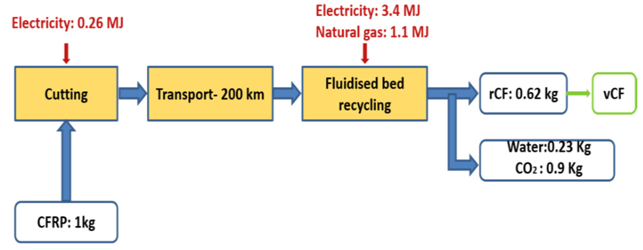
Fluidized Bed (FB) recycling
The software chosen in the present study was a SimaPro 8.3 due to its versatility and wide variety of functionalities. Finally, an Ecoinvent v3.3 was used as a reliable reference database for Life Cycle Inventory (LCI) and IMPACT 2002+ was used as an impact assessment method. The reason that no other tool was chosen, such as the ΕcoCalculator, which is specific to the life cycle analysis of composite materials, is that in addition to composite materials, the life cycle of stainless steel was also studied. Thus, it was necessary to use a tool that provided data for both sets of materials. In addition, SimaPro software and IMPACT 2002+ life cycle impact methodology were used as the most appropriate choices due to compliance with ISO 14040:2006, ISO 14044:2006 and due to European regional validity [
8,
9].
2. Materials and Methods
2.1. Materials
This work outlines the results and the outlook of LCA analysis and waste treatment routes of CFRP materials against stainless steel in the aerospace industry. The materials that are mainly used in the space industry are structural and high-performance components, aiming for the adoption of lightweight solutions and high strength-to-weight ratio materials such as CFRPs over steel to improve fuel efficiency and reduce emissions. The main goal is to emphasize the multiple benefits that result from the use phase which plays a dominant role in the life cycle impacts of the components.
In the case of steel components, the manufacturing process is metal shaping, which is compared to CFRP machining. Specifically, as a raw material, stainless steel contains environmental burdens from the extraction phase. The extraction phase starts from the moment the mineral is collected so that the stainless steel is finally produced.
CFs are produced using PAN-based or pitch-based precursors. The precursor undergoes a series of operations. In the first step, the precursors are oxidized by exposing them to high temperatures. Later, they go through carbonization and graphitization processes. During these processes, precursors go through chemical changes that yield high stiffness-to-weight and strength-to-weight properties. The successive surface treatment and sizing process improves its resin compatibility and handleability. PAN refers to polyacrylonitrile, a polymer fiber of textile origin.
The weight of the end product plays a significant role in the fuel consumption and thus a reduction in the mass is necessary. Weight reduction without any changes to the functionality or safety of the end product can be realized, either by replacing heavier materials with lighter materials (i.e., steel with composite materials) [
10,
11,
12].
Moreover, composite materials give the following advantages over steel to both the aerospace industry and the automotive industry [
13]:
- ➢
Substantial weight reduction: Composites are typically 30–40% lighter than steel parts of equal strength.
- ➢
Unrivaled corrosion resistance: Composites are superior in corrosion resistance for any transportation application.
- ➢
Lowered manufacturing complexity: Finished assemblies with fewer parts cut manufacturing costs and often accelerate design completion and model introduction.
- ➢
Reduced tooling cost: Tooling for composite parts can be as much as 80% less than comparable metal parts.
- ➢
Unparalleled damage resistance: Composites’ dent and ding resistance is far superior to that of steel.
- ➢
Improved design flexibility: Unlike metals, composites offer a limitless “depth-of-draw” range.
- ➢
Cost-effective solutions: Lower composite investment costs satisfy automakers’ trends toward reduced builds per model.
- ➢
Comparable aesthetics: Toughened sheet molded compound (SMC) resin provides “first-time-through” processing comparable to steel.
2.2. Methods
LCA is an environmental accounting and management technique that considers all the facets of resource use and environmental releases associated with an industrial product, material service or a system from the cradle to the grave (
Figure 1) [
14]. Specifically, it is a holistic and comprehensive method for assessing all direct and indirect environmental impacts across the full life cycle of a product, a system that covers a range of activities, from raw materials acquisition, the production through the use, and final disposition of a product (disposal or reuse).
It is worth mentioning that LCA is a well-defined and standardized methodology according to the ISO norms 14044 [
15] and 14044:2006+A1 [
16], and
the International Life Cycle Data Handbook [
17]. The
ILCD Handbook further specifies the provisions of ISO 14044 standards on environmental life cycle assessment. The ILCD system is a collection of publications, documents and tools supporting LCA and LCI high-quality datasets development, publication and sharing.
According to the guidelines mentioned above, LCA is carried out in four stages:
- ·
Goal and Scope Definition
- ·
Life Cycle Inventory
- ·
Life Cycle Impact Assessment
- ·
Interpretation of the Results
The stages along with their interactions are depicted in
Figure 2.
LCA analysis was implemented in accordance with the aforementioned principles to evaluate the ecotoxicological endpoints of steel and CFRPs components manufacturing and use in aerospace, as well as to simulate the beneficial effect of EoL management strategies based on data provided by SpaceCarbon project industrial partners and materials manufacturers in the space sector. In detail, the LCA scenarios and the recycling routes studied and analyzed are described below.
VEGA Launcher Component
LCA has been carried out for a VEGA launcher component (
Figure 3) to compare the production and use phase of the CFRP structure against the conventional stainless steel structure [
18].
2.3. Life Cycle Inventory and General Assumptions
2.3.1. Analysis of the Life Cycle for Vega Launchers Components Made of Steel versus Components Made of CFRPs
Analysis of the LCI or life cycle review is one of the main goals of this systematic investigation. It is a detailed methodology for recording and estimating the consumption of resources, quantities of waste and emissions flows within and outside the product system from the time of extraction of the raw materials to their recovery and recovery of energy. Initially, in a production process, to achieve quantification of materials and energy flows, quantitative data and qualitative inputs, collection of inputs and outputs related to the operation or products generated by the process should be collected. The LCI phase, in other words, the analysis of environmental “interventions” is based on collecting data for each process of a product system.
Data collection to quantify relevant inputs and outputs has been performed for each life cycle scenario related either to the manufacturing process of end products made of CFRPs or the other conventional materials. The processes parameters (i.e., materials, energy flows, chemicals, emissions, and wastes) associated with the launchers production and use and general LCA data relied on the reputable life cycle inventory of the SimaPro professional database, Ecoinvent. In order to fill in any missing data about the establishment of a comprehensive life cycle model covering all product aspects, data was collected based on the best available literature data to carry out and fully document the LCA studies. The energy consumption in the production phase of the VEGA Launcher with CFRP was provided by industrial component manufacturer AVIO and was set to be equal to 10,000 kWh.
Specifically, the Ecoinvent database is used for many life cycle assessment projects, eco-design, and product environmental information. Since 2003, the Ecoinvent database has enabled companies to manufacture their products in greater harmony with the environment, policymakers to implement new policies, and consumers to adopt more environmentally friendly behavior. The Ecoinvent LCI data can be used for life cycle assessment, life cycle management, carbon footprint assessment, water footprint assessment, environmental performance monitoring, product design and eco-design (DfE) or Environmental Product Declarations (EPD).
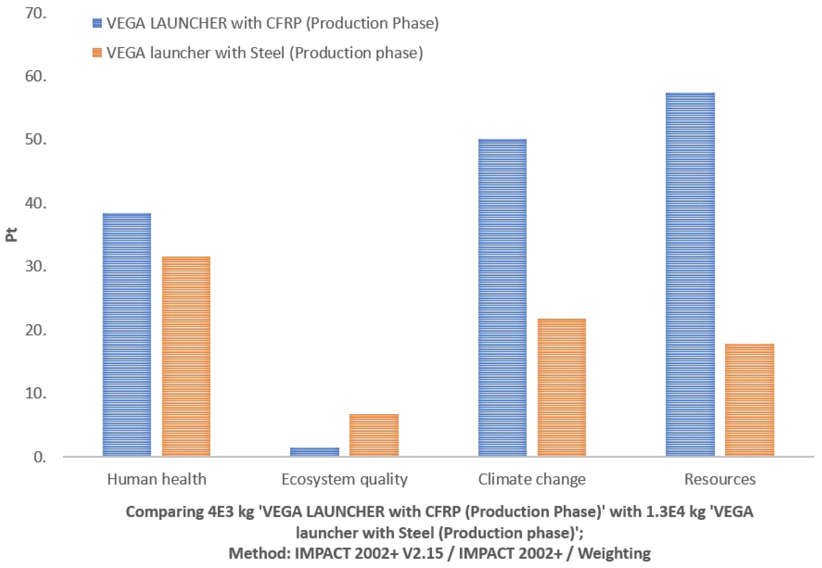
In order to carry out the LCA study of the VEGA launcher component, the following assumptions were made:
| Assumptions for VEGA LAUNCHER Component with CFRP | Assumptions for Hypothetical VEGA LAUNCHER with Stainless Steel |
|---|
| Mass of stainless steel: 13,000 kg Energy consumption: 274,444.4 kWh Lifetime of use: 700,000 km total distance travelled 1169.7 kg helium 406.7 kg hydrazine 1888.6 kg nitrogen
|
For the EoL treatment, disposal and recycling processes are applied in order to minimize the environmental impact of the production and use phases. Realistic scenarios are considered regarding both the recycling rate and the amount of landfilled materials. Additionally, the impacts associated with material recovery and disposal processes are allocated to the end-product life cycle [
18].
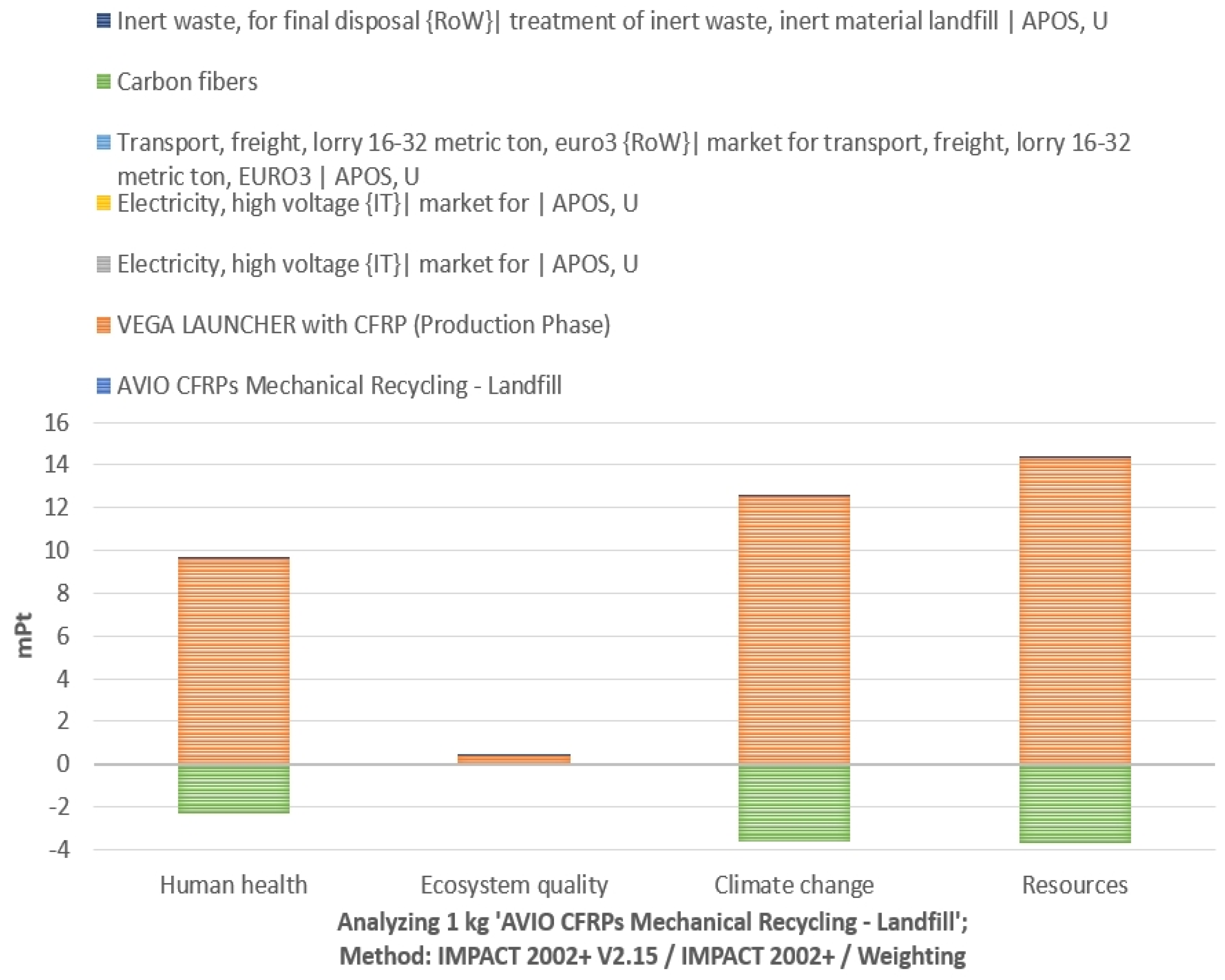
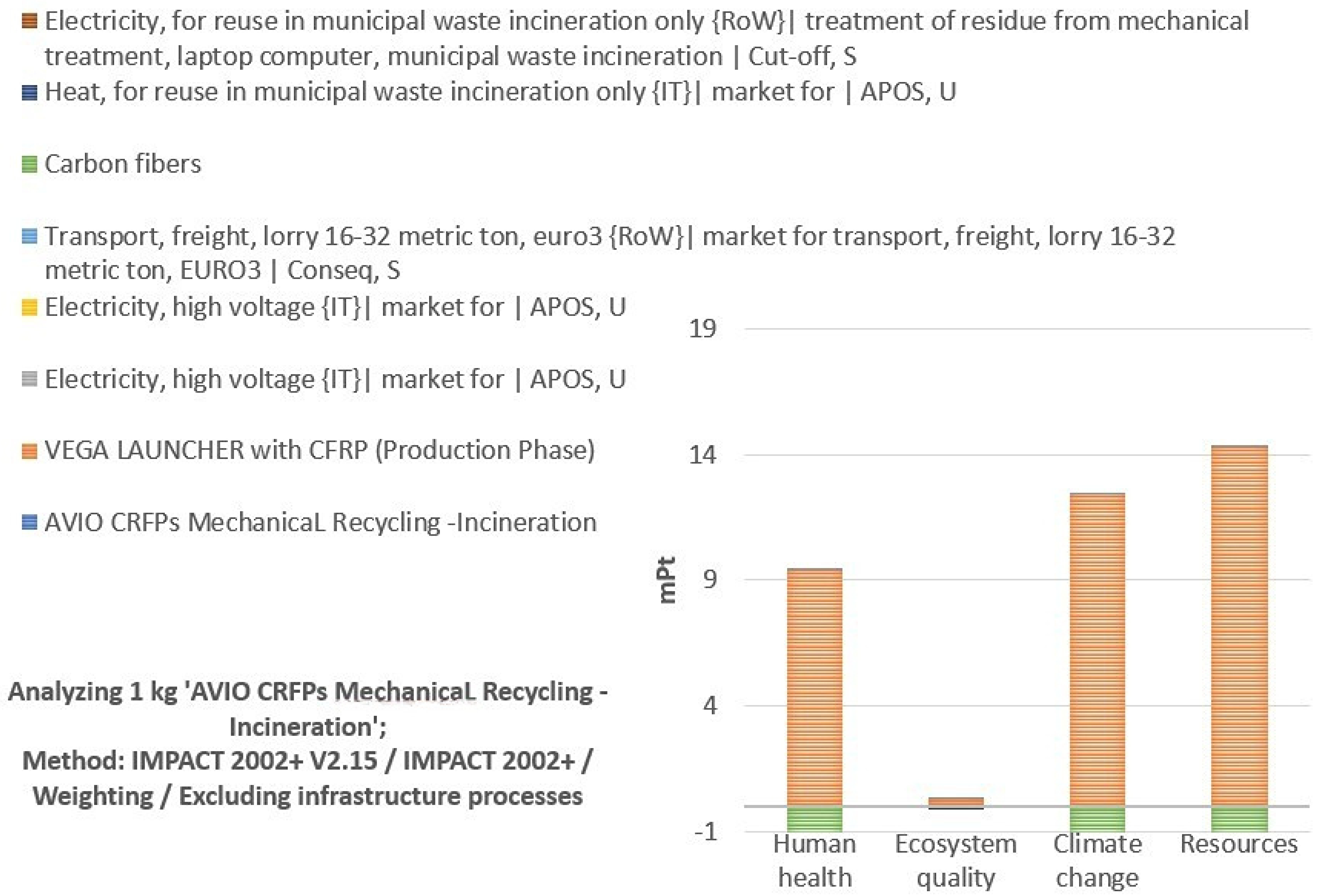
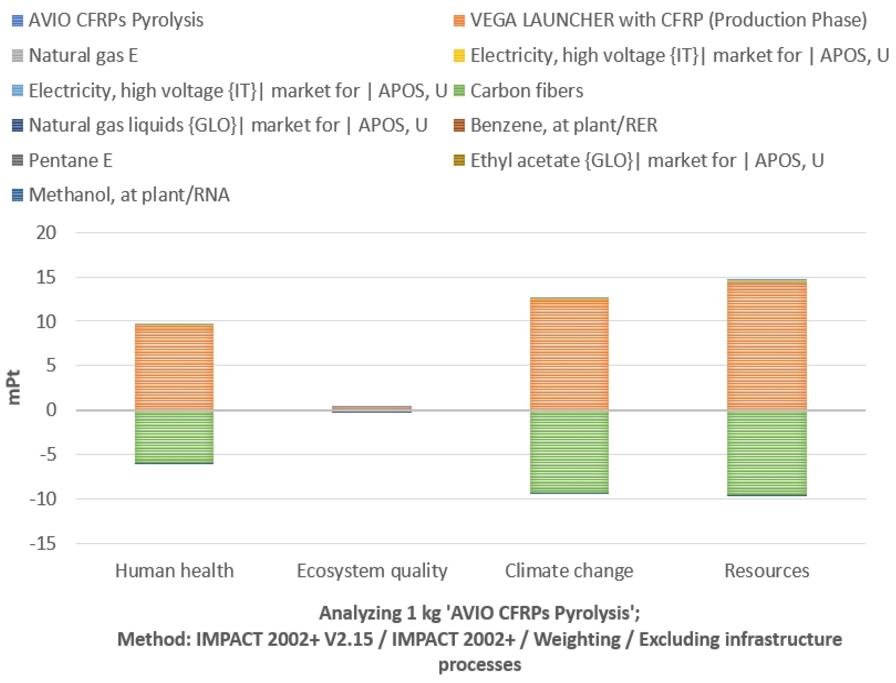
2.3.2. Waste Management Routes
Six potential waste treatment routes for CFRP were considered to reduce the impact connected to the LCA analysis of the production phase: landfill, incineration, mechanical, pyrolysis, fluidized bed, and chemical recycling processes (
Figure 4) [
1]. The values are determined from the literature review. Functional Unit (FU) is 1 kg of CFRP, in this case referring to waste treated from manufacturing scrap or EoL waste from the Vega Launcher product to compare waste management options. FU is the quantified performance of a product system for use as a reference unit (ISO 14040). The choice of FU influences an LCA’s results and care is needed when comparing the results of LCAs with different functional units. The motivation for selecting 1 kg of CFRPs as an FU is due to the scalability, thus providing a usable output for comparing different scenarios, where the component (or any other type of waste of CFRP) is to be recycled and the profile of ecotoxicological behavior is unknown. It is important to note that even if the FU is defined as 1 kg of CFRP, the total mass of the component is imported to the LCA software as an input. Thus, after normalization, the results referring to this FU were grouped and weighted in four areas of influence: human health, ecosystem quality, climate change and resources, and presented in environmental points (Pt), providing indicators that can be compared in future studies and alternative recycling routes, granted that the functional unit used is 1 kg of CFRP.
4. Discussion
LCA is a helpful tool to evaluate the green benefits of the proposed approach as it evaluates the energy and material flow across the life cycle from raw materials extraction to the EoL phase of products, processes or services. It also quantifies the environmental impacts associated with the different disposal scenarios and the definition of robust waste management strategies. The goal of waste treatment policy within the EU is to minimize the impacts of waste on the environment and preserve resources. Recycling is prioritized unless other forms of waste treatment, such as landfill and incineration, prove to be more environmentally appropriate. For composites, impact evaluations through the LCA method of different EoL scenarios have pointed out that recycling is the best option from an environmental point of view. The EU circular economy strategy targets sustainable products in the market to minimize waste, while the EU sets a clear vision for climate neutrality: viable waste management solutions need to be defined for composites [
23].
The goal of the current work is to evaluate through the LCA the impact of launchers consisting of CFRPs in comparison with the other conventional technologies for space, such as stainless steel space vehicle components on the ecosystem, human health, resources and climate change. This research was conducted to assess the entire life cycle of the launcher in order to consider the results of the weight-downsizing of end products, the environmental footprint, and the energy consumption needed for manufacturing technologies. In this way, the aspects of the end-product life cycle that have the most significant contribution to its overall impact can be identified. Specifically, the functional unit (FU) for the study is a VEGA Launcher made of CFRPs or stainless steel with a total life mileage of 700,000 km. LCA based on ISO 14040-14043 will determine the environmental impacts of products, processes or services from production to disposal [
23].
Concretely, in the framework of this study, the LCA was performed in regard to the production phase, the use phase, and the EoL phase of a VEGA launcher component. Moreover, a comparison of the LCA production and use phases, as well as a comparison of all waste management routes was performed. Finally, the EoL comparison concerns the recycling routes for new CFRP solutions for space, including the CFs recovery.
The necessity of developing more eco-friendly processes is a problem affecting the composites sector. CFRP has become a popular material for many industries based principally on its potential for weight savings over conventional materials and the improvement of the ecological profile of service life during the use phase. For this reason, assessment of the environmental impacts and waste management of composites is necessary in order to create awareness and convey engineers’ choices to more sustainable processes. The recycling of composites plays and will play an increasingly vital role in the future for sectors such as the aerospace, automotive, construction and marine sectors. Some conclusions were reached regarding a VEGA launcher component that consists of CFRP or stainless steel, as well as LCA of the production and use phases, and the comparison between them.
First, the ecotoxicological endpoints of the production phase of CFRP versus stainless steel was comparatively more intensive in three end point categories, human health, climate change and resources. This is connected to a higher energy demand in CF production, the use of epoxy resin, higher emissions in the production phase and the petrochemical origin of the CF precursor. In the use phase, LCA analysis demonstrates a notably decreasing environmental impact for CFRPs instead of stainless steel. Moreover, weight reduction directly leads to fuel savings and the reduction of CO
2 emissions and other harmful gas emissions (SOx, NOx). Although the use phase was favorable to CFRP usage, the worst environmental performance in the production phase cannot be overlooked [
3]. In the case of the Vega launcher, the component replacement by CFRPs could not realize the benefits in the use phase, because the Vega launcher demonstrates a certain amount of maximum distance covered (700,000 km) and to this day, the Vega launcher makes a single trip. As soon as the modern objectives of precise redirection and the landing of Vega launchers enables the use of the same Vega launcher multiple times for space missions, the real environmental benefits of using the CFRP technology will become evident.
Moreover, great potential for environmental improvement exists when using LCA within the design stage of any product or process. Specifically, about 80% of environmental effects associated with a product are identified in the design phase of development. In this way, via a redesign of the process and LCA analysis, the substances and materials (solvents, gases) that cause the highest environmental burdens can be identified and limited or even replaced by other substances and materials that are identical in their composition and properties. Further, manufacturing decision-making can be supported and optimized in this regard.
In general, LCA analysis indicates that CFRPs are energy intensive materials. Therefore, CFRPs are ideal candidates for recycling. The establishment of recycling strategies by design was efficiently supported by the LCA analysis of potential recycling routes which can have a measurable effect on the production phase’s environmental footprint, and result in an overall preferable usage of CFRP components over steel components. Since it is a currently evolving field and recycling technologies are still maturing, what is also required for the future of CF re-use is the establishment of proper management strategies to reclaim continuous CFs without any actual cost on their mechanical properties [
24]. Another fact that is worth mentioning is that current metal-based technologies have realized the respective waste management strategies. This is obvious, since the available LCA libraries contain a vast amount of data about the recycling of metal-based structures. However, information regarding CFs and their composites is either missing or not available to access due to confidentiality concerns. In this work, LCA investigation shed light on this field, which is important for the LCA analysis itself while the scientific community continues to move towards the development of technologies for the efficient waste management of CFRPs.
Following this, the goal of waste treatment policy within the EU is to minimize the impacts of waste on the environment and preserve resources. Recycling is prioritized unless other forms of waste treatment, such as landfill and incineration, can be shown to be more environmentally appropriate. For composites, impact evaluations through the LCA method of different EoL scenarios have pointed out that recycling is the best option from an environmental point of view. Further, the EU circular economy strategy targets sustainable products in the market to minimize waste, while the EU sets a clear vision for climate neutrality. Viable waste management solutions need to be defined for composites [
1].
5. Conclusions
It is apparent that emerging research efforts should concentrate on recycling technologies that can reclaim high quality constituents and then remanufacture them into high performance materials, ideally with the goal of providing virgin CFRP performance equivalency. This is also the case for the space sector, where for the studied case of a VEGA launcher a huge amount of CFRPs is used to replace metal components. Data documentation is also emerging to enrich inventory and improve comparative life-cycle impacts, compared to conventional mature technologies, where LCA delivers and optimizes the outcome as the waste management routes mitigate the intensity of ecotoxicological endpoints. Beyond that, recycling and reuse should not be limited to only solid materials, but they could also be utilized in inert gas management, purification, and reuse. Large quantities of nitrogen and argon are required for the production of CFs, and considering the library data, these inert gases contribute to a significant extension of the ecological footprint of CFs production [
25]. Changes and adaptation to current manufacturing facilities of CFs could also be realized by including irradiation and plasma technologies. These changes can reduce the energy wasted in the manufacturing sector [
26]. Irradiation, in contrast to current conventional furnace technologies, does not waste any energy for heating the surrounding atmosphere, but directs the energy to the CF itself. Thus, it is possible to efficiently direct the irradiation energy to the CF intrinsic structure and stereo chemical transformation and provide high performance fibers for aerospace applications. Currently, the adoption of these technologies by industry, as well as access to related data, prevents the realization of the potential impact to establish a quantified approach of this enabling technology for the green transition of carbon fiber manufacturing.
Moreover, recycling is of great importance because it minimizes impacts in the majority impacted categories. LCA results gave a view of the environmental advantages of the recycling process mainly due to material recovery and the potential prospect in the wide adoption of CFRP composites in aerospace. The main point is that rCFs from recovery processes only experience minor degradation of mechanical properties and can be reused in place of vCFs [
1]. Further, the environmental benefits via replacement are primarily achieved by avoiding the production of CF and preserving primary material. Increasing recycling in the production phase and energy optimization may ameliorate the environmental performance. CFRPs are produced by energy intensive processes, and therefore recycling will improve LCA. However, even if there is huge potential to materialize significant environmental benefits through the deployment of CFRP technologies in space, without appropriate remanufacturing technologies able to deliver high performance recycled material, the maximum emission reductions and financial savings from multiple use phases may not be attained [
2].


