Article

Threshold Identification and Damage Characterization of Woven GF/CF Composites under Low-Velocity Impact

School of Aerospace, Transport and Manufacturing Cranfield, Cranfield University, Bedfordshire MK43 0AL, UK
*
Author to whom correspondence should be addressed.
J. Compos. Sci. 2022, 6(10), 305; https://doi.org/10.3390/jcs6100305
Submission received: 1 August 2022 / Revised: 13 September 2022 / Accepted: 8 October 2022 / Published: 11 October 2022
(This article belongs to the Special Issue Characterization and Modelling of Composites, Volume III)

Abstract

:
The Delamination Threshold Load (DTL) is a key parameter representing damage resistance of a laminate and is normally identified by locating a sudden drop in the impact force-time history for the laminate made of unidirectional layers. For the woven composite, however, their failure mechanisms appear different and the current literature is not providing any clear procedure regarding the identification of the delamination initiation, as well as the evolution of the failure mechanisms associated with it. In this paper, experimental data have been collected using woven glass and carbon fiber composites. The results are analyzed in terms of force-time and force-displacement curves. While delamination and other damages were clearly observed using ultrasonic scans, the analysis of the results does not reveal any trend changes of the curves that can be associated with the incipient nucleation of delamination. A preliminary discussion regarding the nature of the mechanisms through which the delamination propagates in woven composite and a justification for the absence of a sudden change of the stiffness have been presented. It raises a question on the existence of DTL for woven composites under low velocity impact.

1. Introduction

Composite laminates are often subjected to low-velocity impacts while in-service and during manufacture. Barely visible impact damage (BVID) is a perception which often neglects the underlying damage introduced within the laminate [1]. Impact energy can be absorbed at any point of the laminate, sometimes far from the impact site due to the inherent material characteristics and brittle nature of fibers and matrix [2]. Although impacting at low energy, there can be various levels of laminate failure mechanisms during energy absorption, including, front face indentation, interlaminar delamination, back face splitting, and fiber peeling [3]. The latter mechanisms are, in some cases, un-inspectable during service and often difficult to detect. These mechanisms interact and coalesce, leading to considerable reductions in stiffness, strength, and load-carrying capability of the structure [4,5]. To support the detection of non-visible damage as well as identify suitable parameters to be used during the design, the existence and validity of threshold load values have been investigated [6,7,8,9,10]. The threshold has been defined either in terms of energy or impact force. The delamination threshold load (DTL) [11,12,13] and Fh (Hertzian Contact Force) [3,9,10] describe a specific damage condition being the significant damage by delamination (DTL) and energy absorption other than by matrix cracking.
Identifying a significant damage event would be by means of detecting a significant load decrease in the force-displacement history before approaching FPeak. A significant load drop would indicate a drastic loss of stiffness within the laminate, indicating large magnitude matrix cracking and delamination [14]. Evidence of difficulties in identifying the DTL and Fh have often led to composite designers to use FPeak as a substitute, which careful consideration shows could detrimental to the life of the component if future loading is considered.
For unidirectional (UD) materials, the identification of the DTL is performed using a method which is robust and reliable. However, for woven materials, it is not as clear as for the UD. Over the years different approaches have been reported in the literature in order to overcome the difficulties in identifying the DTL when dealing with woven. Yasunobu Hirai et al. [15] reported the distribution of different damage types due to low-velocity impact classifying 4 main regions, each of them with a different type of damage. The central region is mainly delamination, whilst the external areas mainly have interface de-bonding. The force-time history used in the discussion of the results do not exhibit any evident sudden decreases, and the “incipient load” is detected as a variation in the slope of the force-displacement curves. In order to shed light on the existence and methods to identify the different type of damages, Schoeppner G.A. and Abrate S. [10] analyzed 500 test results. Where, the tested composites were unidirectional and the samples had a lay-up ranging from 9 to 96 plies. The analysis of the force-time and force-displacement, highlights that variation in the slope of the force-displacement curves, as well as the load drop in the force-time history, can be correlated to matrix cracking and the delamination respectively.
The DTL values for the different configurations are identified using various approaches. M.S. Sohn et al. [16] carried out tests on prepreg carbon fiber with interlayer materials. The analysis of the force-time history curve is carried out considering the force value corresponding to impact load drops due to the first failure. This value is defined as Pi and is called incipient load. In particular, it is shown that with increasing the impact energy the incipient load values increase almost linearly. Although the physical meaning of Pi is equivalent to the DTL, it is depended on the impact energy. Lopes at al. [17] studied the effects of the stacking sequence on the low-velocity impact behavior of composites. Evci and Gulgec [11] have studied the impact response of two different types of E-Glass fabrics. The results reported are referring to UD material as well as woven samples. The Hertzian failure is identified as the first drop in force-time history. The force-time history curves have a linear trend up to the first drop, after which the second linear path is followed up by the maximum load. The threshold load value for the woven is higher than that of the UD, as well as the damaged area. In order to identify a single threshold parameter with which the damage assessment can be performed, energy levels are used and compared with the existing model.
Quaresimin et al. [9] have reported energy absorption characteristics of different composite layup manufactured using carbon woven fabrics. The work is presenting a generalized approach that correlates absorption energy with the impact intensity coefficient. Considerations regarding the delamination threshold load are drawn, although the force-time history curves are not shown and the identification of the DTL value is carried out considering the first drop. The delamination threshold load and the associated energy are matrix-controlled. Zabala et al. [18] have studied the effects of the impact velocity on the delamination of woven carbon-epoxy plates. The identification of the DTL is performed firstly considering three different curve patterns. With no damage induced, the curve appears of a sinusoidal shape. The presence of “oscillations” would point out the presence of delamination. Moreover, the damage is connected to impact energy levels; in particular, sub critical impact, below 1 J, does not induce any damage, the first delamination appear beyond 3 J and fiber fracture is the dominant failure mode above 10 J. Boumbimba et al. [19] reported the low-velocity impact response and damage of laminate composite glass fiber/epoxy. The effect of Nano strength on the impact behavior is assessed in terms of type and evolution of damages as well as energy and force. The force-time history curves reported are different than the typical curves since there is not drop before the maximum load value. The noise observed in the force-time history is used to identify the starting point for the delamination. Evci [6] has reported the results of low-velocity impact tests performed on laminated composites and the effects of the thickness on the energy dissipation characteristics. The threshold is considered in this case as the first drop in the load time history curve. The Hertzian failure is the failure which initiated the delamination and increasing impact load causes further delamination growth. The threshold condition is defined as multiple stage condition where the Hertzian failure force represents the onset of delamination, and the second damage threshold is responsible for the main damage in the form of fiber breakage and laminate failure.
Giannopoulos et al. [7] have recently reported some results of low-velocity impact and compression after impact test results on a woven fiber composite having a fire retardant, syntactic core, two phase epoxy matrix. The first peak point in the force-time history curve indicates damage initiation. In this study however, using filtered impact force-time results, a definitive first load drop was not observable. Instead, following Schoeppner and Abrate [10], the impact force versus deflection diagram was further processed by removing the high-frequency components from it, since the change in slope in the force-time history curve may be associated with the introduction of interplay transverse matrix cracking or localized indentation of the specimen. From the analysis of some of the selected papers dealing with DTL, it is evident that the experimental identification of the threshold condition at the onset of delamination in woven composites is controversial and a robust and reliable method has not yet been found. In the present paper, the results of an experimental investigation carried out the testing glass and carbon woven composites are presented in order to highlight the issues encountered in the identification of the DTL through either the force-time or the force-displacement history curves. In particular, the delamination observed using ultrasonic scanning and thermal imaging techniques were correlated with the trends in the force-time history, with the aim of finding clear evidence to assist in finding a robust and reliable method.

2. Materials and Methods

2.1. Materials and Specimen Compositions

The main objective of this paper is to discuss the issues encountered in the identification of the DTL in woven composites. In order to pursue the above aim, experimental results have been collected testing glass and carbon composite plates under low-velocity impact. Twenty-four specimens for each type of fiber have been manufactured by autoclave. The balanced and symmetric carbon composite plates are composed by 11 laminae arranged in a layup that is [0/90]11. In particular, E720/T300 is a multiple prepreg manufactured by TenCate. TenCate E720 is a toughened epoxy resin system for cures at 120 °C (248 °F), pre-impregnated into high-performance fibers such as carbon and glass. T300 is a woven carbon fiber ply, with a fabric density of 280 GSM, twilled in 2 × 2 weave style. Regarding the glass composite plates, each plate is composed by 11 Texipreg EE300/EF452 laminae arranged in a layup that is [03 903]s. EF452 is a fire retardant, self-adhesive prepreg system which contains no halogenated flame retardants. It is suitable for sandwich panels or solid laminates. EE300 is a plain weave glass fiber ply, with a fabric density of 300 GSM. The final range of thickness values for the carbon and glass composite plates manufactured with the materials above discussed is 4.6 ± 0.06 mm and 3.42 ± 0.02 mm for the carbon and glass composite, respectively.
The mechanical properties of the two systems are reported in Table 1 and Table 2. For each type of fibers, the 24 plates were cut out from a single panel. Low-velocity impact tests have been performed in accordance with ASTM D7136/D7136M [20]. The total mass of the striker was 2.464 kg and diameter of projectile was 25 mm. The energy is controlled by the drop height. The specimens were 100 × 150 mm supported on a rectangular plate and hold with a mechanical clamping apparatus. Time histories of the impact force, velocity, acceleration, and displacement were measured. Impact tests have been performed at six impact energy levels (5 J ÷ 30 J). Prior to impact tests, C-Scan and Infrared thermography analysis have been performed before testing in order to assess that no damages or delamination were present. The damage produced by the impact has been assessed after impact by means of the same two non-destructive methods.

2.2. Impact Tests

The low-velocity impact testing was carried out in accordance with ASTM/D7136M-15 [20] for all samples using an Imatek drop weight tower from variable heights to provide an impact energy equivalent of 5 J, 7.5 J, 10 J, 15 J, 20 J & 30 J. The Load cell used was a calibrated Kistler 9331B in-line load cell connected by a gold-plated coaxial cable attached to a Kistler analyser and Imatek C3008 signal amplifier. The Software used to record the raw data was developed by Imatek Version:3.3.24. (IMATEK, Old Knebworth, Herts, UK).A secondary strike arrestor being built into the Imatek drop tower was also employed and was triggered by a laser guided gate trigger and pneumatic actuator pressure of 70 psi.

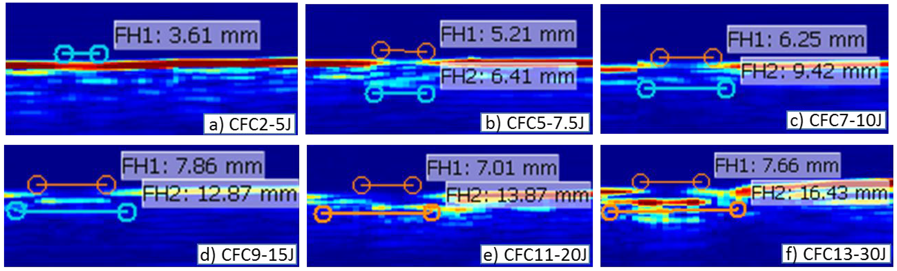
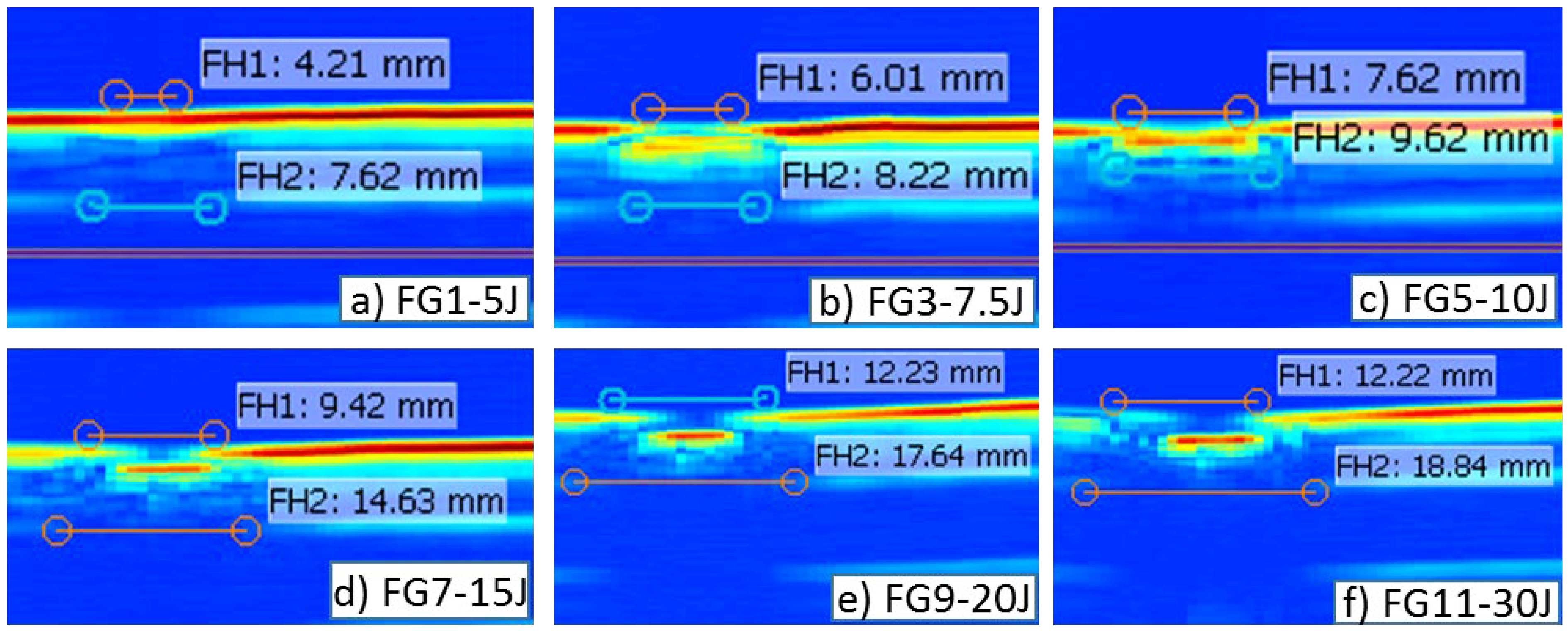
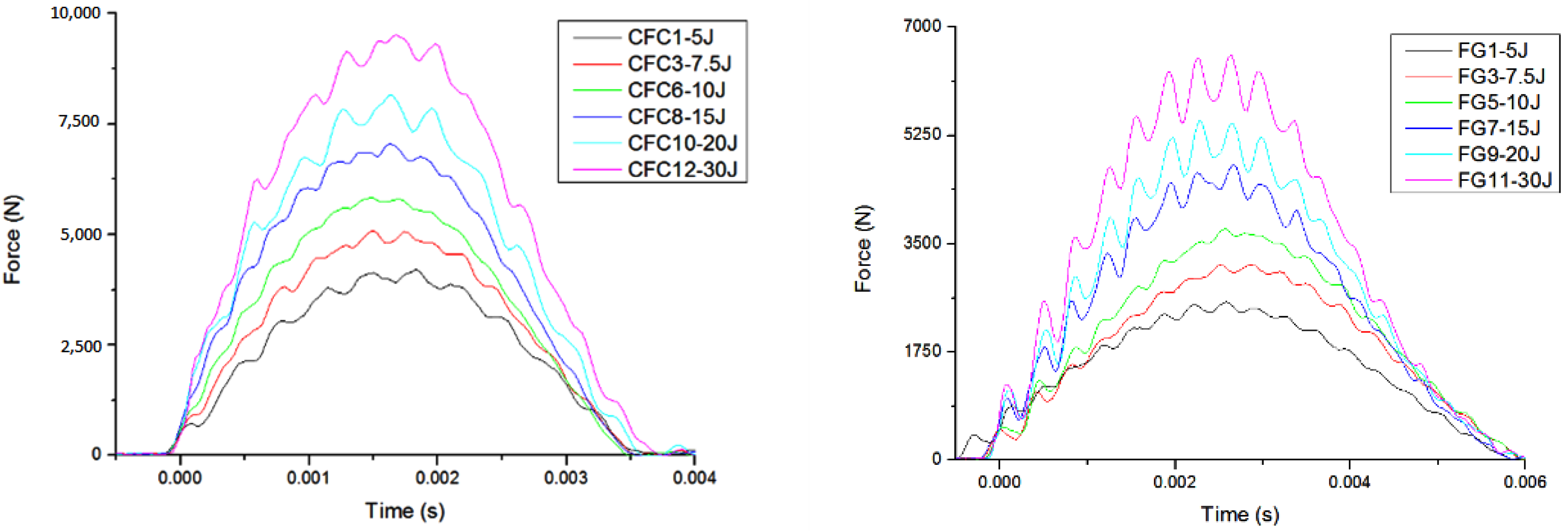
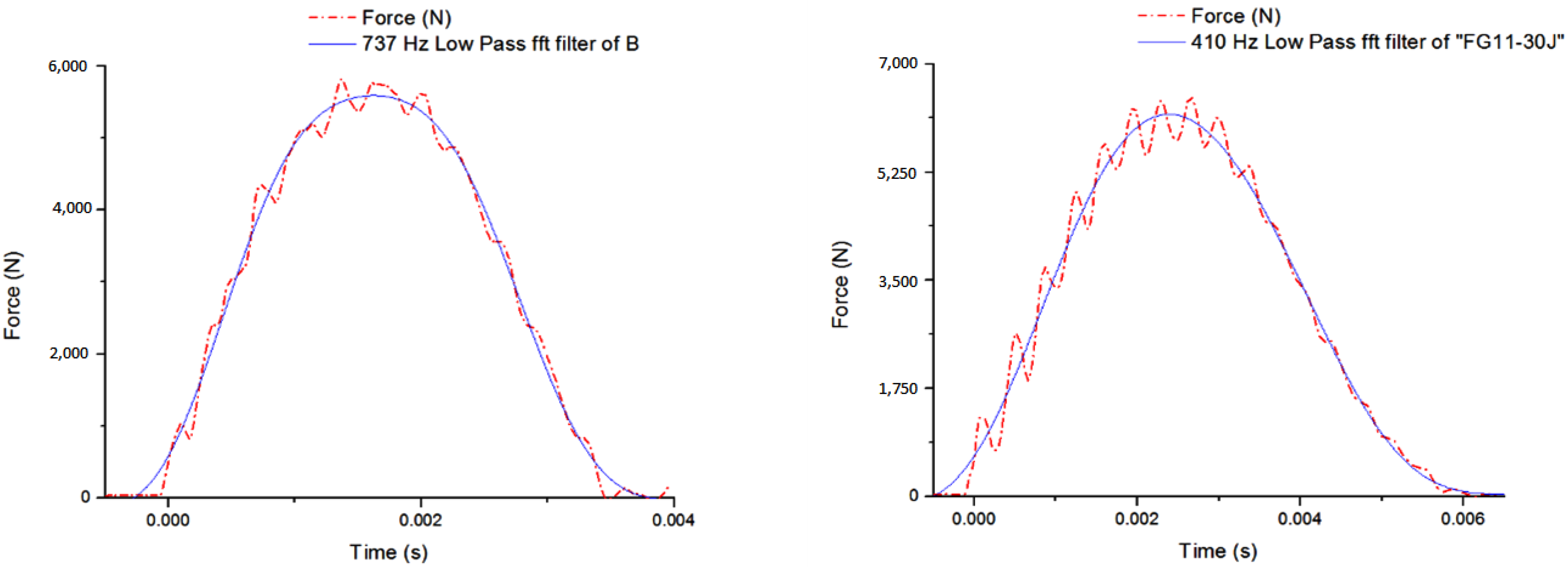
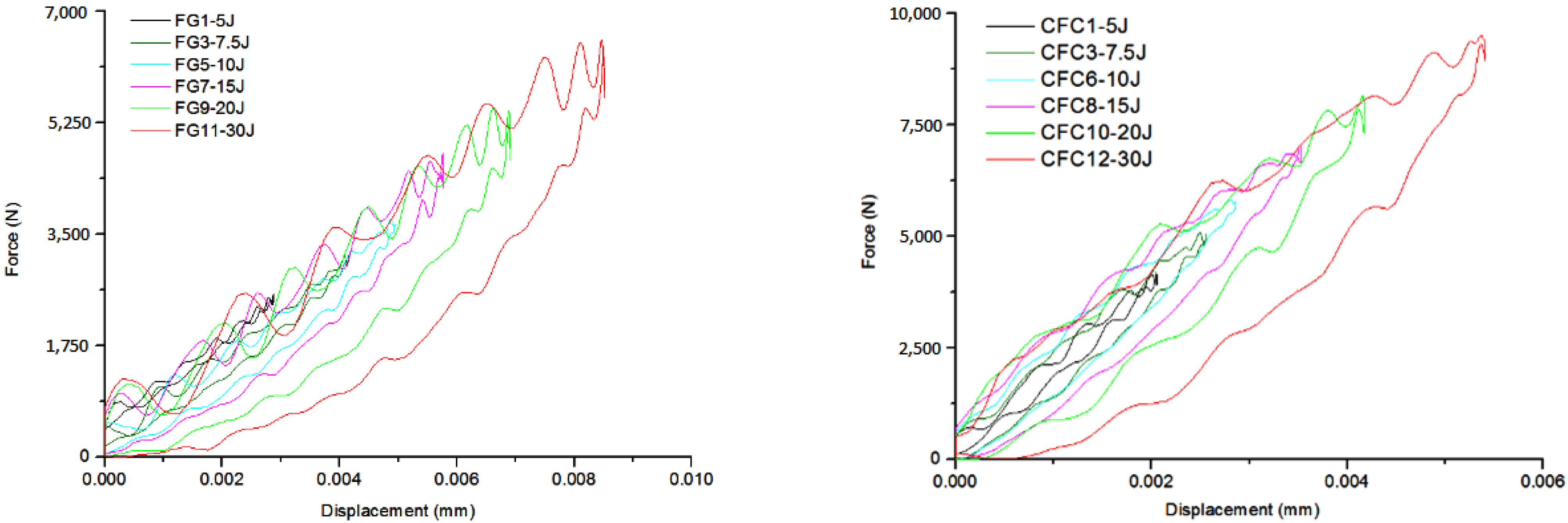
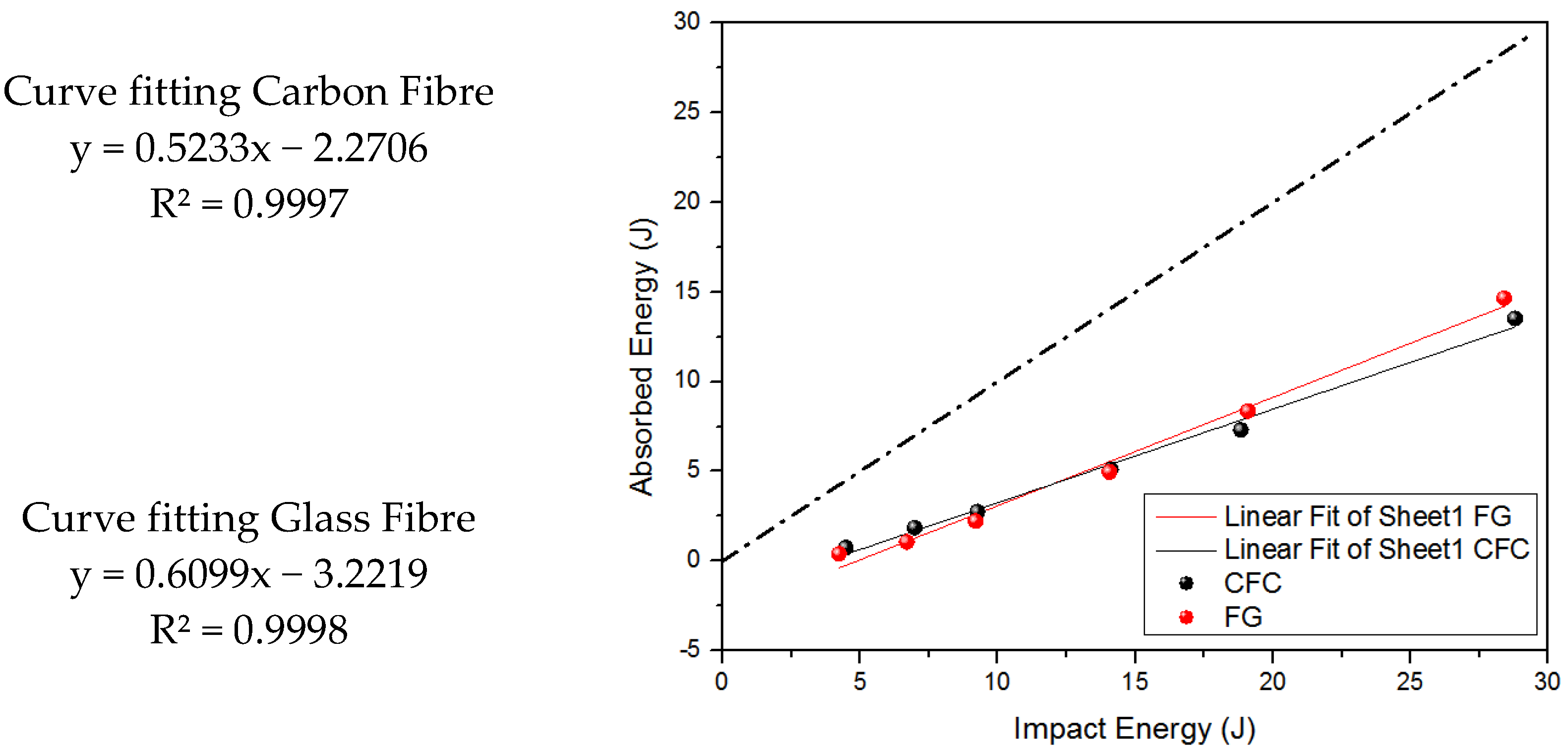
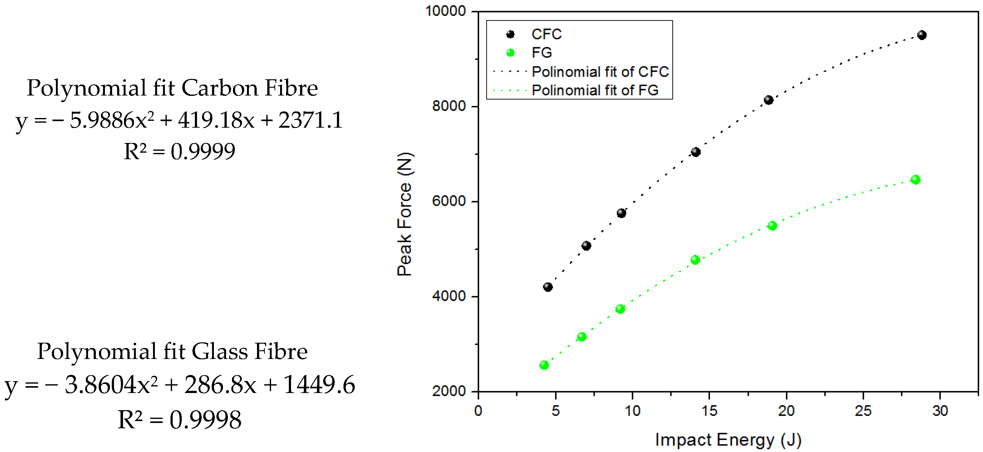
3. Results and Discussion

The main objective of this paper is to assess the possibility of identifying the DTL in woven composite materials through the force-time history curve. Tests have been performed on glass and carbon composite plates in order to collect the experimental data to be analyzed. The results are presented gathering glass and carbon composite plate. Ultrasound scanning techniques using a Sonatest Veo 16:64 with a 45° probe in a water tank have been used in this paper for the detailed identification of the post-impact damage area. The identification of the pine tree fracture pattern [21] is visible in the B-scans (Figure 1 and Figure 2), which is the cross section taken at the impact site location of the C-scan. The calibration method used to identify this internal damage was by accurately measuring the indentation size of each impact site and use this to identify the color contour scaling. It is worth noting that the use of a 45° probe for ultrasonic scanning is not ideal for scanning thick laminates, however for this purpose, the results have been verified by a thermographic method on a number of samples for comparison. The damaged area has been observed to be circular on the surface, however it is worth noting that elliptical measurements have also been recorded. Considering the impactor was a hemispherical shape with 25 mm diameter, the damage shape would indeed be conical in the thickness direction [22]. Higher energies of 30 J would appear to give an elongated conical shape with an elliptical cross. The B-scan measurements have therefore been taken to the semi-major axis of the ellipse (x = 150 mm direction) for a conservative comparison (Figure 1 and Figure 2).
The force-time history curves are shown for carbon and glass composite plates in Figure 3. As reported by other authors [23,24] the curves exhibit oscillations that are due to the resonance effects produced in the sample by the impact load. This occurrence has been observed in UD and now woven materials. As discussed by Giannopoulos et al. [7], although using filtering, is not possible to identify the peak force and the DTL from the impact force time history curve. Additionally, identifying an initial load drop is also not possible, which can be usually be observed for the lower energy impact levels. However, with increasing impact energy, the first drop for the carbon fibers disappears, meaning it cannot be linked to the DTL since it would be evident at any increasing energy level. For the glass fibers, increasing the impact energy amplifies the oscillations in the force-time history curves, which can be explained with the excitation of the vibration modes for the samples.
The use of the force-time history curves is controversial, as reported by Abrate [4], if the effective mass of the plate is taken into account in the solution of the energy balance problem, strong oscillations in the contact force history are observed. These oscillations have the same frequencies as the mode shape of the impacted plate. For the samples investigated in this paper, natural frequencies have been derived for the carbon and glass composites by means of the FFT, the force-time history curves have been filtered. In Figure 4 two examples, one of the carbon and one for the glass composite, are shown. In both cases the signal has been filtered with the 4th mode (m = 2 and n = 2), since it allows the mode shape to be closer to the deformed configuration for the center impact.
The filtered curves are smooth, and any drop is not present, which would be related to the onset of the damage in the composite plate. It can be argued that the low pass filter adopted in this case has a cut-off frequency which is too low cutting away any sign of drop linked to the threshold. However, if the drop corresponding to the DTL is compared to the noise produced by the sample undergoing resonance, it’s simply not possible to clearly identify which drop is the DTL and which is due to the sample vibration.
As suggested by Abrate [4], the assessment of the damage after impact in the composite can also be considered using the slope of the force-displacement curve. This is based on the assumption that the presence of damage has the direct effect of changing the stiffness. The force-displacement history curves for the carbon (left) and the glass (right) fiber are reported in Figure 5.
It can be observed that for the carbon composite there is a variation in slope corresponding to a variation in stiffness at high impact energy. The same behavior is not present in the glass composite, although the investigation after the test has clearly highlighted delamination and damage. The analysis performed for the carbon composite allowed identification of the force corresponding to the change in slope. Although it is a variation in stiffness and as reported by [4] it represents a variation in stiffness along the transversal direction, it can be due to a combination of interlaminar and intralaminar damages, fiber fractures as well as delamination.
The analysis of the above graphs highlights two main limitations. On one hand, the threshold cannot be identified for glass composite, whilst on the other hand, it seems possible for carbon composites for higher energies. For the latter, damages without delamination are observed under 5 J impact energy, however there is no evident variation in the force-displacement slope. Moreover, the value of the force corresponding to the slope change under 7.5 J, is lower than that observed at higher energy levels. As demonstrated by other authors [3,9,25], the DTL is constant with impact energy, meaning either the values reported are measuring overall effects and is not solely related to the delamination, or the DTL is not constant with the impact energy. Moreover, as reported by Zabala [18], the delamination is usually the dominant failure mechanism at lower impact energy, whilst at higher energy, matrix cracking and fiber fracture play the major role. The above observations encourage the authors to consider the variation in slope as a measure of the overall damage, rather than the value at which the delamination starts to propagate.
The absorbed energy has been computed as the area under the force-displacement curve. In Figure 6, the energy profile diagram is shown together with the equal energy curve. All data points are above the equal curve since the penetration energy was never reached [26]. Comparison between the glass and carbon fibers show that at lower impact energy, the carbon composite plates absorb more energy compared to the glass composite. However, when increasing the impact energy, the glass fibers absorb more energy, resulting in several damage types induced in varying ways. According to Cantwell and Morton [27], the fibers with higher strain at failure perform better at higher impact energy. Moreover, the matrix, plays a major role in interlaminar damage since the damage initiation is matrix-dominant [28]. Yang et al. [13] have used the value of the peak force as the force to initiate damage. It is also observed that the rapid drop in the impact force has not been observed. The onset of damage is detected visually by inspecting the samples after impact. According to Belingardi and Vadori [29], the value of the peak force increases with impact energy. The use of the maximum peak as a threshold for the delamination is in contrast with the definition of DTL since it is a function of the impact energy and cannot be considered as material properties (Figure 7).
As reported by Kim and Sham [30], low velocity impact tests performed on woven composites show neither a load drop nor slope changes until the load reached the maximum. The first failure event can be represented by the incipient load drop or a sudden change in force-displacement slope, depending on the type of woven composite. However, the major role is played by the matrix since the higher its ductility, the higher possibility of initial damage being a load drop. For the particular composite investigated in this paper, the combination of matrix ductility, strength of fiber-matrix bonding and the interlaminar fracture toughness (GIIC) are responsible for the shape of the force-time history curve in which a load drop is not evident. The initial damage should occur at the maximum load Pm. However, the mechanisms by which the damage grows is not fully explored for the woven. A possible explanation is that damage is induced while loading and the growth of the delamination is sustained by the increasing load. The stiffness of the samples would not be affected due to the delamination not reaching the critical toughness, implying that the “crack” would not become unstable and the force-time history would not have any sudden decrease. The above hypothesis requires further experimental tests in order to further explore the failure mechanisms.

4. Conclusions

This paper presents an experimental investigation on the identification of delamination threshold load (DTL) of woven GF/CF composite laminates under low velocity impact. Key conclusions from the analysis of the experimental data are:
  • It has been observed that, although the damage could be clearly identified through C-scan and sectional B-scans, there is no noticeable sudden load drop or slope change of the impact force curves for the woven composites.
  • This different behavior has been rationalized with a difference in the mechanisms involved in the initiation and propagation of the delamination of the woven composite under low velocity impact.
  • For the type of layup and material investigated in this paper, the interlaminar damage induced by the impact is growing progressively without causing any sudden change of the stiffness.
  • The combination of matrix ductility, strength of the fiber-matrix bonding and the interlaminar fracture toughness (GIIC) are responsible for the shape of the force-time history curve in which a sudden load drop is not evident.
It raises a question on the existence of DTL for woven composite laminates under low velocity impact. The preliminary results presented in this paper represent a first step in understanding the delamination under low-velocity impact for woven composites. Further testing and analysis is required to clarify the relevance of DTL concept to woven composite laminates.

Author Contributions

M.G. Formal Analysis; M.G. and Y.X. Experimental Data; M.G. writing original draft; M.G. and Y.X. Review & Editing. All authors have read and agreed to the published version of the manuscript.

Funding

This research received no external funding.

Institutional Review Board Statement

Not applicable.

Informed Consent Statement

Not applicable.

Data Availability Statement

The data that support the findings of this study are available on request from the corresponding author. The data are not publicly available due to privacy or ethical restrictions.

Acknowledgments

The Authors would like to thank Amit Ramji for the support with the experimental work.

Conflicts of Interest

The authors declare no conflict of interest.

References

  1. Grasso, M.; Xu, Y.; Ramji, A.; Zhou, G.; Chrysanthou, A.; Haritos, G.; Chen, Y. Low-velocity impact behaviour of woven laminate plates with fire retardant resin. Compos. Part B Eng. 2019, 171, 1–8. [Google Scholar] [CrossRef]
  2. Ramji, A.; Xu, Y.; Grasso, M.; Yasaee, M.; Webb, P. Effect of interfacial fibre orientation and PPS veil density on delamination resistance of 5HS woven CFRP laminates under mode II loading. Compos. Sci. Technol. 2021, 207, 108735. [Google Scholar] [CrossRef]
  3. Xu, Y.G.; Shen, Z.; Tiu, W.; Xu, Y.Z.; Chen, Y.K.; Haritos, G. Delamination threshold load of composite laminates under low-velocity impact. In Key Engineering Materials; Trans Tech Publications: Stafa-Zurich, Switzerland, 2013; Volume 525, pp. 521–524. [Google Scholar]
  4. Abrate, S. Impact on Composite Structures; Cambridge University Press: Cambridge, UK, 1998; ISBN 0521473896. [Google Scholar]
  5. Ramji, A.; Xu, Y.; Yasaee, M.; Grasso, M.; Webb, P. Influence of veil interleave distribution on the delamination resistance of cross-ply CFRP laminates under low velocity impact. Int. J. Impact Eng. 2021, 157, 103997. [Google Scholar] [CrossRef]
  6. Evci, C. Thickness-dependent energy dissipation characteristics of laminated composites subjected to low velocity impact. Compos. Struct. 2015, 133, 508–521. [Google Scholar] [CrossRef]
  7. Giannopoulos, I.K.; Theotokoglou, E.E.; Zhang, X. Impact damage and CAI strength of a woven CFRP material with fire retardant properties. Compos. Part B Eng. 2016, 91, 8–17. [Google Scholar] [CrossRef] [Green Version]
  8. Grasso, M.; Penta, F.; Pucillo, G.P.; Ricci, F.; Rosiello, V. Low velocity impact response of composite panels for aeronautical applications. In Lecture Notes in Engineering and Computer Science; Proceedings of The World Congress on Engineering: London, UK, 2015; Volume 2218, p. 2218. [Google Scholar]
  9. Quaresimin, M.; Ricotta, M.; Martello, L.; Mian, S. Energy absorption in composite laminates under impact loading. Compos. Part B Eng. 2013, 44, 133–140. [Google Scholar] [CrossRef]
  10. Schoeppner, G.A.; Abrate, S. Delamination threshold loads for low velocity impact on composite laminates. Compos. Part A Appl. Sci. Manuf. 2000, 31, 903–915. [Google Scholar] [CrossRef]
  11. Evci, C.; Gülgeç, M. An experimental investigation on the impact response of composite materials. Int. J. Impact Eng. 2012, 43, 40–51. [Google Scholar] [CrossRef]
  12. Lee, S.M.; Zahuta, P. Instrumented impact and static indentation of composites. J. Compos. Mater. 1991, 25, 204–222. [Google Scholar] [CrossRef] [Green Version]
  13. Yang, F.J.; Cantwell, W.J. Impact damage initiation in composite materials. Compos. Sci. Technol. 2010, 70, 336–342. [Google Scholar] [CrossRef]
  14. Stamoulis, K.; Georgantzinos, S.K.; Giannopoulos, G.I. Damage characteristics in laminated composite structures subjected to low-velocity impact. Int. J. Struct. Integr. 2019, 11, 670–685. [Google Scholar] [CrossRef]
  15. Hirai, Y.; Hamada, H.; Kim, J.-K. Impact response of woven glass-fabric composites—I.: Effect of fibre surface treatment. Compos. Sci. Technol. 1998, 58, 91–104. [Google Scholar] [CrossRef]
  16. Sohn, M.S.; Hu, X.Z.; Kim, J.K.; Walker, L. Impact damage characterisation of carbon fibre/epoxy composites with multi-layer reinforcement. Compos. Part B Eng. 2000, 31, 681–691. [Google Scholar] [CrossRef]
  17. Lopes, C.S.; Seresta, O.; Coquet, Y.; Gürdal, Z.; Camanho, P.P.; Thuis, B. Low-velocity impact damage on dispersed stacking sequence laminates. Part I: Experiments. Compos. Sci. Technol. 2009, 69, 926–936. [Google Scholar] [CrossRef]
  18. Zabala, H.; Aretxabaleta, L.; Castillo, G.; Urien, J.; Aurrekoetxea, J. Impact velocity effect on the delamination of woven carbon–epoxy plates subjected to low-velocity equienergetic impact loads. Compos. Sci. Technol. 2014, 94, 48–53. [Google Scholar] [CrossRef]
  19. Boumbimba, R.M.; Froustey, C.; Viot, P.; Gerard, P. Low velocity impact response and damage of laminate composite glass fibre/epoxy based tri-block copolymer. Compos. Part B Eng. 2015, 76, 332–342. [Google Scholar] [CrossRef] [Green Version]
  20. ASTM, D7136. Standard Test Method for Measuring the Damage Resistance of a Fiber-Reinforced Polymer Matrix Composite to a Dropweight Impact Event. 2005. Available online: https://oss.jishulink.com/upload/201912/2aa7bc89034f4a5ea4617e2ae0ba553a.pdf (accessed on 7 October 2022).
  21. Liu, D. Characterization of impact properties and damage process of glass/epoxy composite laminates. J. Compos. Mater. 2004, 38, 1425–1442. [Google Scholar] [CrossRef]
  22. Mitrevski, T.; Marshall, I.H.; Thomson, R. The influence of impactor shape on the damage to composite laminates. Compos. Struct. 2006, 76, 116–122. [Google Scholar] [CrossRef]
  23. Abrate, S. Impact Engineering of Composite Structures; Springer Science & Business Media: Berlin/Heidelberg, Germany, 2011; Volume 526, ISBN 3709105234. [Google Scholar]
  24. Reis, P.N.B.; Ferreira, J.A.M.; Zhang, Z.Y.; Benameur, T.; Richardson, M.O.W. Impact response of Kevlar composites with nanoclay enhanced epoxy matrix. Compos. Part B Eng. 2013, 46, 7–14. [Google Scholar] [CrossRef]
  25. Liu, D.; Raju, B.B.; Dang, X. Impact perforation resistance of laminated and assembled composite plates. Int. J. Impact Eng. 2000, 24, 733–746. [Google Scholar] [CrossRef]
  26. Aktaş, M.; Atas, C.; İçten, B.M.; Karakuzu, R. An experimental investigation of the impact response of composite laminates. Compos. Struct. 2009, 87, 307–313. [Google Scholar] [CrossRef]
  27. Cantwell, W.J.; Morton, J. The impact resistance of composite materials—A review. Composites 1991, 22, 347–362. [Google Scholar] [CrossRef]
  28. Griffin, C.F. Damage Tolerance of Toughened Resin Graphite Composites; ASTM International: Hampton, VA, USA, 1987. [Google Scholar]
  29. Belingardi, G.; Vadori, R. Influence of the laminate thickness in low velocity impact behavior of composite material plate. Compos. Struct. 2003, 61, 27–38. [Google Scholar] [CrossRef]
  30. Kim, J.-K.; Sham, M.-L. Impact and delamination failure of woven-fabric composites. Compos. Sci. Technol. 2000, 60, 745–761. [Google Scholar] [CrossRef]
Figure 1. Damage characterisation B-Scans—Carbon Fibre—5 J to 30 J (af).
Jcs 06 00305 g001
Figure 2. Damage characterization B-Scans—Glass Fiber—5 J to 30 J (af).
Jcs 06 00305 g002
Figure 3. Force time history for Carbon (left) and Glass (right) fibers tested.
Jcs 06 00305 g003
Figure 4. Comparison between the as acquired and low pass filtered curves.
Jcs 06 00305 g004
Figure 5. Force displacement curves for carbon fibers (left) and glass fibers (right).
Jcs 06 00305 g005
Figure 6. Energy profile with the equal energy curve.
Jcs 06 00305 g006
Figure 7. Peak force as a function of the impact energy for the carbon fibers (black) and glass fibers (green).
Jcs 06 00305 g007
Table 1. Mechanical Properties of Carbon Fiber.
PropertyConditionMethodResults
Tensile StrengthRTDEN ISO 524-4621MPa
Tensile ModulusRTDEN ISO 524-458.4GPa
Poisson’s Ratio0.05
Compression StrengthRTDEN 2850488MPa
Compression ModulusRTDEN 285070GPa
In-Plane Shear StrengthRTDEN ISO 1412999MPa
In-Plane Shear ModulusRTDEN ISO 141293.5GPa
Flexural StrengthRTDEN ISO 14125801MPa
Flexural ModulusRTDEN ISO 1412552.4GPa
ILSSRTDEN ISO 1413062.1MPa
RTD—Room Temperature Dry.
Table 2. Mechanical Properties of Glass Fiber.
Cured Material Properties 1UnitTypical ValueStandard Method
Cured Ply Thicknessmm0.22
Tensile Strength MPa450ASTM D 3039
Tensile Modulus GPa22ASTM D 3039
Flexural Strength MPa480ASTM D 790
Flexural ModulusGPa24ASTM D 790
Compressive Strength MPaN/AModified ASTM D695 (SACMA SRM 1-88)
I.L.S.S. MPa35ASTM D 2344
1 The tests were carried out @ 23 °C and 60% R.H. on specimens cured in std conditions (dwell @150° for 1 h in hot plate press. External pressure applied: 3 bar). The tests were performed along the warp direction.
Publisher’s Note: MDPI stays neutral with regard to jurisdictional claims in published maps and institutional affiliations.

