
New Advances and Future Possibilities in Forming Technology of Hybrid Metal–Polymer Composites Used in Aerospace Applications

 ,
,  ,
, 
 and
and
Abstract
:1. Introduction
2. Classification of FMLs
3. Fabrication of FMLs
- applying an adhesion promoter;
- mechanical treatment (e.g., grinding and sandblasting);
- the use of chemical or electrochemical treatment (e.g., etching with hydrofluoric acid and dry surface treatments).
- resistance to electric (atmospheric) discharge [207],
4. Press-Brake Bending
5. Shot Peening Forming
6. Incremental Sheet Forming
6.1. Background
- bilayer polymeric sheets [264],
6.2. Application of SPIF to Hybrid Metal–Polymer Composites
7. Lay-Up Technique
- hand lay-up,
- spray lay-up,
- compression moulding,
- poltrusion,
- resin transfer moulding (RTM), and
- filament winding.
- an appropriate injection pressure gradient,
- good wettability in the fibre–resin system, and
- good tightness of the impregnation system.
8. Die Forming
8.1. Stamping
8.2. Hydroforming
8.3. Electromagnetic Forming
8.4. Laser Forming
9. Summary and Future Trends
- Up to now, the target industry associated with FMLs has been the aviation industry focused on the use of lightweight components with relatively high strength. Progress in plastic forming technologies is also stimulated by developments in the automotive industry, which are full of exogenous innovations, primarily new production technologies and a new machine park. In the context of the Industry 4.0 concept, the development of the technology of plastic processing of aluminium alloy-based FMLs can be a stimulus for the introduction of innovative materials in the shipbuilding industry, in the production of yachts, autonomous vehicles, and light personal air land vehicles.
- Research on forming aluminium alloy-based FMLs commonly used in aerospace applications has been extended to other materials such as titanium and steel. The latter material, when used as a component of composites, can lower manufacturing costs in the automotive industry. Pressure from governments to reduce CO2 emissions from transport will increase. In this context, weight reduction will continue to be the focus of vehicle manufacturers, and composites and other lightweight construction materials will play an increasingly important role.
- Press-brake bending of single curvature components is being replaced by alternative laser bending technologies and the formation of shot peening. Existing research confirms their high efficiency when bending plates with large curvatures and in many planes at the same time. However, due to the longer processing time, these methods are most productive in small lot production.
- The growing interest of industry in lightweight and high strength composite structures brings the need to solve the problem of ensuring subsequent ecological recycling. It is necessary to develop new technologies for the management of post-consumer waste or to modify the current technology of producing FMLs. Thermoplastics have lower strength and a lower modulus of elasticity than epoxy or polyester resins, but show better recyclability.
- The new opportunities created by material engineering allow the fabrication of new FMLs with previously unknown properties, as well as modifying those already known in order to adapt them to new applications and reduce production and material costs. Currently, investigations are conducted on the use of nanofillers, such as single-walled or multi-walled nanotubes, to strengthen and stiffen composites.
- One of the ways to increase the deformability of composites using plastic working methods is to perform the forming process at an elevated temperature. Although an increase in temperature improved the formability of composites, the forming temperature is limited by the melting temperature of the polymer matrix and the glass transition temperature of HMPC. The temperature windows for HMPC forming are not well understood because most of the industrially used composites are still being shaped in cold forming conditions.
- Increasing the productivity and lowering the cost of producing composites is possible through the use of optimal material combinations of layers of thin metal sheets and composite. The introduction of cheap, high strength steel sheets and new thermoplastic polymers may open new windows for the use of composites that are cheap to produce and easy to recycle.
- Reducing the prices of components for the production of composites, as well as the dissemination of automated manufacturing methods, such as filament winding and RTM, have led to the development of 3D reinforcement-based spatial laminates. Designers show greater confidence in such composites than in classic composites due to the elimination of the risk of delamination.
- A critical failure phenomenon in metal–fibre laminates, in addition to poor adhesion at the metal–composite interface, is poor adhesion at the reinforcing fibre–matrix interface, leading to delamination. In order to achieve the desired shape-dimensional quality of FML elements and optimal formability, an in-depth understanding of the mechanisms of their forming, including the use of non-destructive methods of defect detection, is required.
Author Contributions
Funding
Institutional Review Board Statement
Informed Consent Statement
Data Availability Statement
Conflicts of Interest
References
- Yamada, K.; Kötter, B.; Nishikawa, M.; Fukudome, S.; Matsuda, N.; Kawabe, K.; Fiedler, B.; Hojo, M. Mechanical Properties and Failure Mode of Thin-Ply Fiber Metal Laminates under out-of-Plane Loading. Compos. Part A Appl. Sci. Manuf. 2021, 143, 106267. [Google Scholar] [CrossRef]
- Rao, N.N.; Rao, P.M.V.; Kumar, S. A Numerical Approach to Estimate First Ply Failure of Fibre Metal Laminate. Rev. Compos. Matériaux Av. 2021, 31, 33–39. [Google Scholar] [CrossRef]
- Frącz, W.; Janowski, G. Predicting effect of fiber orientation on chosen strength properties of wood-polymer composites. Compos. Theory Pract. 2019, 19, 56–63. [Google Scholar]
- Mottaghian, F.; Yaghoobi, H.; Taheri, F. Numerical and Experimental Investigations into Post-Buckling Responses of Stainless Steel- and Magnesium-Based 3D-Fiber Metal Laminates Reinforced by Basalt and Glass Fabrics. Compos. Part B Eng. 2020, 200, 108300. [Google Scholar] [CrossRef]
- Cortés, P.; Cantwell, W.J. The Fracture Properties of a Fibre–Metal Laminate Based on Magnesium Alloy. Compos. Part B Eng. 2005, 37, 163–170. [Google Scholar] [CrossRef]
- Alderliesten, R.; Rans, C.; Benedictus, R. The Applicability of Magnesium Based Fibre Metal Laminates in Aerospace Structures. Compos. Sci. Technol. 2008, 68, 2983–2993. [Google Scholar] [CrossRef]
- Sharma, A.P.; Velmurugan, R.; Shankar, K.; Ha, S. High-Velocity Impact Response of Titanium-Based Fiber Metal Laminates. Part II: Analytical Modeling. Int. J. Impact Eng. 2021, 152, 103853. [Google Scholar] [CrossRef]
- Sharma, A.P.; Velmurugan, R. Uni-Axial Tensile Response and Failure of Glass Fiber Reinforced Titanium Laminates. Thin-Walled Struct. 2020, 154, 106859. [Google Scholar] [CrossRef]
- Rahiminejad, D.; Compston, P. The Effect of Pre-Heat Temperature on the Formability of a Glass-Fibre/Polypropylene and Steel-Based Fibre–Metal Laminate. Int. J. Mater. Form. 2021, 14, 715–727. [Google Scholar] [CrossRef]
- van Rooijen, R.G.J.; Sinke, J.; van der Zwaag, S. Improving the Adhesion of Thin Stainless Steel Sheets for Fibre Metal Laminate (FML) Applications. J. Adhes. Sci. Technol. 2005, 19, 1387–1396. [Google Scholar] [CrossRef]
- Dreaves, A. Potential Use of Fibre-Steel Laminates in Hybrid Deck Systems. Master’s Thesis, Delft University of Technology, Delft, The Netherlands, 2018. [Google Scholar]
- Park, S.Y.; Choi, W.J. The Guidelines of Material Design and Process Control on Hybrid Fiber Metal Laminate for Aircraft Structures. In Optimum Composite Structures; Maalawi, J., Ed.; IntechOpen: London, UK, 2019; pp. 125–168. [Google Scholar]
- Monsalve, A.; Parra, L.; Baeza, D.; Solís, R.; Palza, H. Mechanical Properties and Morphological Characteristics of ARALL Reinforced with TRGO Doped Epoxy Resin. Matéria 2018, 23. [Google Scholar] [CrossRef]
- Jerome, J.; Hynes, N.R.J.; Sankaranarayanan, R. Mechanical Behavioural Testing of Fibre Metal Laminate Composites. AIP Conf. Proc. 2020, 2220, 140035. [Google Scholar] [CrossRef]
- Chen, Y.; Wang, Y.; Wang, H. Research Progress on Interlaminar Failure Behavior of Fiber Metal Laminates. Adv. Polym. Technol. 2020, 2020, 3097839. [Google Scholar] [CrossRef]
- Asghar, W.; Nasir, M.A.; Qayyum, F.; Shah, M.; Azeem, M.; Nauman, S.; Khushnood, S. Investigation of Fatigue Crack Growth Rate in CARALL, ARALL and GLARE. Fatigue Fract. Eng. Mater. Struct. 2017, 40, 1086–1100. [Google Scholar] [CrossRef]
- Sinmazçelik, T.; Avcu, E.; Bora, M.Ö.; Çoban, O. A Review: Fibre Metal Laminates, Background, Bonding Types and Applied Test Methods. Mater. Des. 2011, 32, 3671–3685. [Google Scholar] [CrossRef]
- Lin, Y.; Huang, Y.; Huang, T.; Liao, B.; Zhang, D.; Li, C. Characterization of Progressive Damage Behaviour and Failure Mechanisms of Carbon Fibre Reinforced Aluminium Laminates under Three-Point Bending. Thin-Walled Struct. 2019, 135, 494–506. [Google Scholar] [CrossRef]
- Vermeeren, C.A.J.R. The Application of Carbon Fibres in ARALL Laminates; Report LR-658; Delft University of Technology, Faculty of Aerospace Engineering: Delft, The Netherlands, 1991. [Google Scholar]
- Shi, Y.; Pinna, C.; Soutis, C. Impact Damage Characteristics of Carbon Fibre Metal Laminates: Experiments and Simulation. Appl. Compos. Mater. 2020, 27, 511–531. [Google Scholar] [CrossRef]
- Kubit, A.; Trzepieciński, T.; Krasowski, B.; Slota, J.; Spišák, E. Strength Analysis of a Rib-Stiffened GLARE-Based Thin-Walled Structure. Materials 2020, 13, 2929. [Google Scholar] [CrossRef]
- Blala, H.; Lang, L.; Khan, S.; Li, L. A Comparative Study on the GLARE Stamp Forming Behavior Using Cured and Non-Cured Preparation Followed by Hot-Pressing. Int. J. Adv. Manuf. Technol. 2021, 115, 1461–1473. [Google Scholar] [CrossRef]
- Abouhamzeh, M.; Smyth, N.; Sinke, J. On the Measurement of Residual Stresses in Fibre Metal Laminates. Int. J. Adv. Manuf. Technol. 2021, 113, 1663–1671. [Google Scholar] [CrossRef]
- Giurgiutiu, V. Chapter 1—Introduction. In Structural Health Monitoring of Aerospace Composites; Giurgiutiu, V., Ed.; Academic Press: Oxford, UK, 2016; pp. 1–23. [Google Scholar]
- Teresko, J. Boeing 787: A Matter of Materials—Special Report: Anatomy of a Supply Chain. Available online: https://www.industryweek.com/leadership/companies-executives/article/21942033/boeing-787-a-matter-of-materials-special-report-anatomy-of-a-supply-chain (accessed on 15 June 2021).
- Ucan, H.; Scheller, J.; Nguyen, C.; Nieberl, D.; Beumler, T.; Haschenburger, A.; Meister, S.; Kappel, E.; Prussak, R.; Deden, D.; et al. Automated, Quality Assured and High Volume Oriented Production of Fiber Metal Laminates (FML) for the Next Generation of Passenger Aircraft Fuselage Shells. Sci. Eng. Compos. Mater. 2019, 26, 502–508. [Google Scholar] [CrossRef]
- Bachmann, J.; Hidalgo, C.; Bricout, S. Environmental Analysis of Innovative Sustainable Composites with Potential Use in Aviation Sector—A Life Cycle Assessment Review. Sci. China Technol. Sci. 2017, 60, 1301–1317. [Google Scholar] [CrossRef] [Green Version]
- Tadini, P.; Grange, N.; Chetehouna, K.; Gascoin, N.; Senave, S.; Reynaud, I. Thermal Degradation Analysis of Innovative PEKK-Based Carbon Composites for High-Temperature Aeronautical Components. Aerosp. Sci. Technol. 2017, 65, 106–116. [Google Scholar] [CrossRef] [Green Version]
- Aamir, M.; Tolouei-Rad, M.; Giasin, K.; Nosrati, A. Recent Advances in Drilling of Carbon Fiber–Reinforced Polymers for Aerospace Applications: A Review. Int. J. Adv. Manuf. Technol. 2019, 105, 2289–2308. [Google Scholar] [CrossRef]
- Hassanalian, M.; Abdelkefi, A. Classifications, Applications, and Design Challenges of Drones: A Review. Prog. Aerosp. Sci. 2017, 91, 99–131. [Google Scholar] [CrossRef]
- Hassanalian, M.; Rice, D.; Abdelkefi, A. Evolution of Space Drones for Planetary Exploration: A Review. Prog. Aerosp. Sci. 2018, 97, 61–105. [Google Scholar] [CrossRef]
- Xu, Y.; Zhu, J.; Wu, Z.; Cao, Y.; Zhao, Y.; Zhang, W. A Review on the Design of Laminated Composite Structures: Constant and Variable Stiffness Design and Topology Optimization. Adv. Compos. Hybrid Mater. 2018, 1, 460–477. [Google Scholar] [CrossRef]
- Ye, J.; Wang, H.; Dong, J.; Liu, C.; Gao, Y.; Gong, B.; Su, B.; Peng, H.-X. Metal Surface Nanopatterning for Enhanced Interfacial Adhesion in Fiber Metal Laminates. Compos. Sci. Technol. 2021, 205, 108651. [Google Scholar] [CrossRef]
- Rubio-González, C.; Chávez, F.; José-Trujillo, E.; Rodríguez-González, J.A.; Ruiz, A. Impact Behavior of Carbon Fiber/Epoxy Composites and Fiber Metal Laminates with Open Holes. Fibers Polym. 2021, 22, 772–785. [Google Scholar] [CrossRef]
- Wu, X.; Zhan, L.; Huang, M.; Zhao, X.; Wang, X.; Zhao, G. Corrosion Damage Evolution and Mechanical Properties of Carbon Fiber Reinforced Aluminum Laminate. J. Cent. South Univ. 2021, 28, 657–668. [Google Scholar] [CrossRef]
- Wang, C.; Yao, L.; He, W.; Cui, X.; Wu, J.; Xie, D. Effect of Elliptical Notches on Mechanical Response and Progressive Damage of FMLs under Tensile Loading. Thin-Walled Struct. 2020, 154, 106866. [Google Scholar] [CrossRef]
- Pan, L.; Wang, Y.; Hu, Y.; Lv, Y.; Ali, A.; Roy, N.; Ma, W.; Tao, J. Investigation on the Effect of Configuration on Tensile and Flexural Properties of Aluminum/Self-Reinforced Polypropylene Fiber Metal Laminates. J. Sandw. Struct. Mater. 2020, 22, 1770–1785. [Google Scholar] [CrossRef]
- Logesh, K.; Hariharasakthisudhan, P.; Rajan, B.S.; Moshi, A.A.M.; Khalkar, V. Effect of Multi-Walled Carbon Nano-Tube on Mechanical Behavior of Glass Laminate Aluminum Reinforced Epoxy Composites. Polym. Compos. 2020, 41, 4849–4860. [Google Scholar] [CrossRef]
- Zhu, W.; Xiao, H.; Wang, J.; Li, X. Effect of Coupling Agent Quantity on Composite Interface Structure and Properties of Fiber Metal Laminates. Polym. Compos. 2021, 42, 3195–3205. [Google Scholar] [CrossRef]
- Zhou, X.; Zhao, Y.; Chen, X.; Liu, Z.; Li, J.; Fan, Y. Fabrication and Mechanical Properties of Novel CFRP/Mg Alloy Hybrid Laminates with Enhanced Interface Adhesion. Mater. Des. 2021, 197, 109251. [Google Scholar] [CrossRef]
- Li, L.; Lang, L.; Hamza, B.; Zhang, Q. Effect of Hydroforming Process on the Formability of Fiber Metal Laminates Using Semi-Cured Preparation. Int. J. Adv. Manuf. Technol. 2020, 107, 3909–3920. [Google Scholar] [CrossRef]
- Morgado, M.A.; Carbas, R.J.C.; Marques, E.A.S.; da Silva, L.F.M. Reinforcement of CFRP Single Lap Joints Using Metal Laminates. Compos. Struct. 2019, 230, 111492. [Google Scholar] [CrossRef]
- Nassir, N.A.; Birch, R.S.; Cantwell, W.J.; Al Teneiji, M.; Guan, Z.W. The Perforation Resistance of Aluminum-Based Thermoplastic FMLs. Appl. Compos. Mater. 2021, 28, 587–605. [Google Scholar] [CrossRef]
- Bikakis, G.S.; Kalfountzos, C.D.; Theotokoglou, E.E. Elastic Buckling of Rectangular Fiber-Metal Laminated Plates under Uniaxial Compression. J. Thermoplast. Compos. Mater. 2020, 33, 1629–1651. [Google Scholar] [CrossRef]
- Zhang, X.; Meng, W.; Zhang, T.; Huang, X.; Hou, S. Analysis and Research on Solution Method of Metal Layer Stress in Fiber Metal Laminates. Mater. Res. Express 2020, 7, 116514. [Google Scholar] [CrossRef]
- Yelamanchi, B.; MacDonald, E.; Gonzalez-Canche, N.G.; Carrillo, J.G.; Cortes, P. The Mechanical Properties of Fiber Metal Laminates Based on 3D Printed Composites. Materials 2020, 13, 5264. [Google Scholar] [CrossRef]
- Minchenkov, K.; Vedernikov, A.; Safonov, A.; Akhatov, I. Thermoplastic Pultrusion: A Review. Polymers 2021, 13, 180. [Google Scholar] [CrossRef] [PubMed]
- Park, S.Y.; Choi, W.J.; Choi, H.S. A Comparative Study on the Properties of GLARE Laminates Cured by Autoclave and Autoclave Consolidation Followed by Oven Postcuring. Int. J. Adv. Manuf. Technol. 2010, 49, 605–613. [Google Scholar] [CrossRef]
- Poodts, E.; Ghelli, D.; Brugo, T.; Panciroli, R.; Minak, G. Experimental Characterization of a Fiber Metal Laminate for Underwater Applications. Compos. Struct. 2015, 129, 36–46. [Google Scholar] [CrossRef]
- Keshavarz, R.; Aghamohammadi, H.; Eslami-Farsani, R. The Effect of Graphene Nanoplatelets on the Flexural Properties of Fiber Metal Laminates under Marine Environmental Conditions. Int. J. Adhes. Adhes. 2020, 103, 102709. [Google Scholar] [CrossRef]
- Li, H.; Hu, Y.; Xu, Y.; Wang, W.; Zheng, X.; Liu, H.; Tao, J. Reinforcement Effects of Aluminum–Lithium Alloy on the Mechanical Properties of Novel Fiber Metal Laminate. Compos. Part B Eng. 2015, 82, 72–77. [Google Scholar] [CrossRef]
- Ding, Z.; Wang, H.; Luo, J.; Li, N. A Review on Forming Technologies of Fibre Metal Laminates. Int. J. Lightweight Mater. Manuf. 2021, 4, 110–126. [Google Scholar] [CrossRef]
- Wang, H.; Tao, J.; Jin, K. The Effect of MWCNTs with Different Diameters on the Interface Properties of Ti/CFRP Fiber Metal Laminates. Compos. Struct. 2021, 266, 113818. [Google Scholar] [CrossRef]
- Kiss, P.; Glinz, J.; Stadlbauer, W.; Burgstaller, C.; Archodoulaki, V.-M. The Effect of Thermally Desized Carbon Fibre Reinforcement on the Flexural and Impact Properties of PA6, PPS and PEEK Composite Laminates: A Comparative Study. Compos. Part B Eng. 2021, 215, 108844. [Google Scholar] [CrossRef]
- Lin, L.; Schlarb, A.K. Development and Optimization of High-Performance PEEK/CF/Nanosilica Hybrid Composites. Polym. Adv. Technol. 2021, 32, 3150–3159. [Google Scholar] [CrossRef]
- Reyes, G.; Gupta, S. Manufacturing and Mechanical Properties of Thermoplastic Hybrid Laminates Based on DP500 Steel. Compos. Part A Appl. Sci. Manuf. 2009, 40, 176–183. [Google Scholar] [CrossRef]
- Iriondo, J.; Aretxabaleta, L.; Aizpuru, A. Characterisation of the Elastic and Damping Properties of Traditional FML and FML Based on a Self-Reinforced Polypropylene. Compos. Struct. 2015, 131, 47–54. [Google Scholar] [CrossRef]
- Prasad, E.V.; Sivateja, C.; Sahu, S.K. Effect of Nanoalumina on Fatigue Characteristics of Fiber Metal Laminates. Polym. Test. 2020, 85, 106441. [Google Scholar] [CrossRef]
- Meng, X.; Yao, L.; Wang, C.; He, W.; Xie, L.; Zhang, H. Investigation on the Low-Velocity Impact Behaviour of Non-Symmetric FMLs—Experimental and Numerical Methods. Int. J. Crashworthiness 2020, 1–19. [Google Scholar] [CrossRef]
- Muthukumar, C.; Ishak, M.; Sapuan, S.; Leman, Z.; Jawaid, M.; Jesuarockiam, N. Mechanical Properties of a Novel Fibre Metal Laminate Reinforced with the Carbon, Flax, and Sugar Palm Fibres. Bioresources 2018, 13, 5725–5739. [Google Scholar] [CrossRef]
- Ebrahimnezhad-Khaljiri, H.; Eslami-Farsani, R.; Talebi, S. Investigating the High Velocity Impact Behavior of the Laminated Composites of Aluminum/Jute Fibers- Epoxy Containing Nanoclay Particles. Fibers Polym. 2020, 21, 2607–2613. [Google Scholar] [CrossRef]
- Abd El-baky, M.; Alshorbagy, A.; Alsaeedy, A.; Megahed, M. Fabrication of Cost Effective Fiber Metal Laminates Based on Jute and Glass Fabrics for Enhanced Mechanical Properties. J. Nat. Fibers 2020, 1–16. [Google Scholar] [CrossRef]
- Hussain, M.; Imad, A.; Saouab, A.; Nawab, Y.; Kanit, T.; Herbelot, C.; Muhammad, K. Properties and Characterization of Novel 3D Jute Reinforced Natural Fibre Aluminium Laminates. J. Compos. Mater. 2020, 55, 1879–1891. [Google Scholar] [CrossRef]
- Mohammed, I.; Abu Talib, A.R.; Sultan, M.T.H.; Jawaid, M.; Ariffin, A.H.; Saadon, S. Mechanical Properties of Fibre-Metal Laminates Made of Natural/Synthetic Fibre Composites. BioResources 2018, 13, 2022–2034. [Google Scholar] [CrossRef]
- Aghamohammadi, H.; Eslami-Farsani, R.; Tcharkhtchi, A. The Effect of Multi-Walled Carbon Nanotubes on the Mechanical Behavior of Basalt Fibers Metal Laminates: An Experimental Study. Int. J. Adhes. Adhes. 2020, 98, 102538. [Google Scholar] [CrossRef]
- Abbandanak, S.; Azghan, M.; Zamani, A.; Fallahnejad, M.; Farsani, R.; Siadati, M.H. Effect of Graphene on the Interfacial and Mechanical Properties of Hybrid Glass/Kevlar Fiber Metal Laminates. J. Ind. Text. 2020, 1528083720932222. [Google Scholar] [CrossRef]
- Eslami-Farsani, R.; Aghamohammadi, H.; Khalili, S.M.R.; Ebrahimnezhad-Khaljiri, H.; Jalali, H. Recent Trend in Developing Advanced Fiber Metal Laminates Reinforced with Nanoparticles: A Review Study. J. Ind. Text. 2020, 1528083720947106. [Google Scholar] [CrossRef]
- PRISMA. Available online: http://www.prisma-statement.org/ (accessed on 25 June 2021).
- Sinke, J. Development of Fibre Metal Laminates: Concurrent Multi-Scale Modeling and Testing. J. Mater. Sci. 2006, 41, 6777–6788. [Google Scholar] [CrossRef]
- Vlot, A.; Vogelesang, L.B.; de Vries, T.J. Towards Application of Fibre Metal Laminates in Large Aircraft. Aircr. Eng. Aerosp. Technol. 1999, 71, 558–570. [Google Scholar] [CrossRef]
- Vlot, A. Glare: History of the Development of a New Aircraft Material; Springer: Dordrecht, The Netherlands, 2001. [Google Scholar]
- Vermeeren, C.A.J.R. An Historic Overview of the Development of Fibre Metal Laminates. Appl. Compos. Mater. 2003, 10, 189–205. [Google Scholar] [CrossRef]
- Alderliesten, R.C.; Schut, J.E. Delamination Growth Rate at Low and Elevated Temperatures in GLARE. In Proceedings of the 25th International Congres on the Aeronautical Sciences, Hamburg, Germany, 3–8 September 2006; Available online: http://www.icas.org/ICAS_ARCHIVE/ICAS2006/PAPERS/148.PDF (accessed on 12 July 2021).
- Vogelesang, L.B.; Gunnink, J.W. Arall: A Materials Challenge for the next Generation of Aircraft. Mater. Des. 1986, 7, 287–300. [Google Scholar] [CrossRef]
- Vogelesang, L.B.; Gunnink, J.W.; Chen, D.; Roebroeks, G.H.J.J.; Vlot, A. New Developments in ARALL Laminates. In Proceedings of the International Council of the Aeronautical Sciences (ICAS) Conference, Jerusalem, Israel, 28 August 1988; pp. 1615–1633. [Google Scholar]
- Vogelesang, L.B.; Vlot, A. Development of Fibre Metal Laminates for Advanced Aerospace Structures. J. Mater. Process. Technol. 2000, 103, 1–5. [Google Scholar] [CrossRef]
- Moussavi-Torshizi, S.E.; Dariushi, S.; Sadighi, M.; Safarpour, P. A Study on Tensile Properties of a Novel Fiber/Metal Laminates. Mater. Sci. Eng. A 2010, 527, 4920–4925. [Google Scholar] [CrossRef]
- Sinke, J. Manufacturing Principles for Fiber Metal Laminates. Available online: https://www.semanticscholar.org/paper/MANUFACTURING-PRINCIPLES-FOR-FIBER-METAL-LAMINATES-Sinke/0895984469cc00f46aca4267b31e61329c27a8eb (accessed on 26 June 2021).
- Kaleeswaran, P.; KiranBabu, K.M.; Kumar, B.S. Fabrication of Fibre Metal Laminate (FML) and Evaluation of Its Mechanical Properties. Int. J. Appl. Eng. Res. 2014, 9, 8872–8874. [Google Scholar]
- de Boer, T. Next Generation Fibre Metal Laminates. In Fibre Metal Laminates: An Introduction; Vlot, A., Gunnink, J.W., Eds.; Springer: Dordrecht, The Netherlands, 2001; pp. 39–51. [Google Scholar]
- Kuznetsova, R.; Ergun, H.; Liaw, B. Acoustic Emission of Failure in Fiber-Metal Laminates. In Nondestructive Testing of Materials and Structures; Büyüköztürk, O., Taşdemir, M.A., Güneş, O., Akkaya, Y., Eds.; Springer: Dordrecht, The Netherlands, 2013; pp. 619–625. [Google Scholar]
- Mohamed, G.F.A.; Soutis, C.; Hodzic, A. Blast Resistance and Damage Modelling of Fibre Metal Laminates to Blast Loads. Appl. Compos. Mater. 2012, 19, 619–636. [Google Scholar] [CrossRef]
- Carey, C.; Cantwell, W.J.; Dearden, G.; Edwards, K.R.; Edwardson, S.P.; Watkins, K.G. Towards a Rapid, Non-Contact Shaping Method for Fibre Metal Laminates Using a Laser Source. Int. J. Adv. Manuf. Technol. 2010, 47, 557–565. [Google Scholar] [CrossRef]
- Tarpani, A.C.S.P.; Barreto, T.A.; Tarpani, J.R. Fatigue Failure Analysis of Riveted Fibre-Metal Laminate Lap Joints. Eng. Fract. Mech. 2020, 239, 107275. [Google Scholar] [CrossRef]
- Kashfi, M.; Majzoobi, G.H.; Bonora, N.; Iannitti, G.; Ruggiero, A.; Khademi, E. A New Overall Nonlinear Damage Model for Fiber Metal Laminates Based on Continuum Damage Mechanics. Eng. Fract. Mech. 2019, 206, 21–33. [Google Scholar] [CrossRef]
- Blala, H.; Lang, L.; Li, L.; Alexandrov, S. Deep Drawing of Fiber Metal Laminates Using an Innovative Material Design and Manufacturing Process. Compos. Commun. 2021, 23, 100590. [Google Scholar] [CrossRef]
- Xu, P.; Zhou, Z.; Liu, T.; Mal, A. Determination of Geometric Role and Damage Assessment in Hybrid Fiber Metal Laminate (FML) Joints Based on Acoustic Emission. Compos. Struct. 2021, 270, 114068. [Google Scholar] [CrossRef]
- Frizzell, R.M.; McCarthy, C.T.; McCarthy, M.A. A Comparative Study of the Pin-Bearing Responses of Two Glass-Based Fibre Metal Laminates. Compos. Sci. Technol. 2008, 68, 3314–3321. [Google Scholar] [CrossRef]
- McCarthy, M.A.; Xiao, J.R.; Petrinic, N.; Kamoulakos, A.; Melito, V. Modelling of Bird Strike on an Aircraft Wing Leading Edge Made from Fibre Metal Laminates—Part 1: Material Modelling. Appl. Compos. Mater. 2004, 11, 295–315. [Google Scholar] [CrossRef]
- Wilk, M.S.; Śliwa, R.E. The influence of features of aluminium alloys 2024, 6061 and 7075 on the properties of Glare-type composites. Arch. Metall. Mater. 2015, 60, 3101–3108. [Google Scholar] [CrossRef]
- Figueroa, J.G.M.; Llanas, P.I.A. Fracture Toughness of Fiber Metal Laminates through the Concepts of Stiffness and Strain-Intensity-Factor. In Proceedings of the 17th International Conference on New Trends in Fatigue and Fracture, Cancun, Mexico, 25–27 October 2017; Ambriz, R.R., Jaramillo, D., Plascencia, G., Nait Abdelaziz, M., Eds.; Springer International Publishing: Cham, Germany, 2018; pp. 313–328. [Google Scholar]
- Backman, D.; Patterson, E.A. Effect of Cold Working on Crack Growth from Holes in Fiber Metal Laminates. Exp. Mech. 2012, 52, 1033–1045. [Google Scholar] [CrossRef]
- Khan, S.H.; Sharma, A.P. Failure Assessment of Fiber Metal Laminates Based on Metal Layer Dispersion under Dynamic Loading Scenario. Eng. Fail. Anal. 2019, 106, 104182. [Google Scholar] [CrossRef]
- Merzuki, M.N.M.; Ma, Q.; Rejab, M.R.M.; Sani, M.S.M.; Zhang, B. Experimental and Numerical Investigation of Fibre-Metal-Laminates (FMLs) under Free Vibration Analysis. Mater. Today Proc. 2021, S2214785321015297. [Google Scholar] [CrossRef]
- Keipour, S.; Gerdooei, M. Springback Behavior of Fiber Metal Laminates in Hat-Shaped Draw Bending Process: Experimental and Numerical Evaluation. Int. J. Adv. Manuf. Technol. 2019, 100, 1755–1765. [Google Scholar] [CrossRef]
- Taheri-Behrooz, F.; Shokrieh, M.M.; Yahyapour, I. Effect of Stacking Sequence on Failure Mode of Fiber Metal Laminates under Low-Velocity Impact. Iran Polym. J. 2014, 23, 147–152. [Google Scholar] [CrossRef]
- Wang, J.; Li, J.; Fu, C.; Zhang, G.; Zhu, W.; Li, X.; Yanagimoto, J. Study on Influencing Factors of Bending Springback for Metal Fiber Laminates. Compos. Struct. 2021, 261, 113558. [Google Scholar] [CrossRef]
- Mahendrarajah, G.; Kandare, E.; Khatibi, A.A. Enhancing the Fracture Toughness Properties by Introducing Anchored Nano-Architectures at the Metal–FRP Composite Interface. J. Compos. Sci. 2019, 3, 17. [Google Scholar] [CrossRef] [Green Version]
- Sadighi, M.; Pärnänen, T.; Alderliesten, R.C.; Sayeaftabi, M.; Benedictus, R. Experimental and Numerical Investigation of Metal Type and Thickness Effects on the Impact Resistance of Fiber Metal Laminates. Appl. Compos. Mater. 2012, 19, 545–559. [Google Scholar] [CrossRef]
- Russig, C.; Bambach, M.; Hirt, G.; Holtmann, N. Shot Peen Forming of Fiber Metal Laminates on the Example of GLARE®. Int. J. Mater. Form. 2014, 7, 425–438. [Google Scholar] [CrossRef]
- Reyes, G.; Cantwell, W.J. The Effect of Strain Rate on the Interfacial Fracture Properties of Carbon Fiber-Metal Laminates. J. Mater. Sci. Lett. 1998, 17, 1953–1955. [Google Scholar] [CrossRef]
- Li, L.; Lang, L.; Khan, S.; Wang, Y. Investigation into Effect of the Graphene Oxide Addition on the Mechanical Properties of the Fiber Metal Laminates. Polym. Test. 2020, 91, 106766. [Google Scholar] [CrossRef]
- Cepeda-Jiménez, C.M.; Alderliesten, R.C.; Ruano, O.A.; Carreño, F. Damage Tolerance Assessment by Bend and Shear Tests of Two Multilayer Composites: Glass Fibre Reinforced Metal Laminate and Aluminium Roll-Bonded Laminate. Compos. Sci. Technol. 2009, 69, 343–348. [Google Scholar] [CrossRef] [Green Version]
- Kuang, K.S.C.; Cantwell, W.J.; Zhang, L.; Bennion, I.; Maalej, M.; Quek, S.T. Damage Monitoring in Aluminum-Foam Sandwich Structures Based on Thermoplastic Fibre-Metal Laminates Using Fibre Bragg Gratings. Compos. Sci. Technol. 2005, 65, 1800–1807. [Google Scholar] [CrossRef]
- Langdon, G.; Nurick, G.; Lemanski, S.; Simmons, M.; Cantwell, W.; Schleyer, G. Failure Characterisation of Blast-Loaded Fibre–Metal Laminate Panels Based on Aluminium and Glass–Fibre Reinforced Polypropylene. Compos. Sci. Technol. 2007, 67, 1385–1405. [Google Scholar] [CrossRef]
- Abdullah, M.R.; Prawoto, Y.; Cantwell, W.J. Interfacial Fracture of the Fibre-Metal Laminates Based on Fibre Reinforced Thermoplastics. Mater. Des. 2015, 66, 446–452. [Google Scholar] [CrossRef]
- Vo, T.P.; Guan, Z.W.; Cantwell, W.J.; Schleyer, G.K. Modelling of the Low-Impulse Blast Behaviour of Fibre–Metal Laminates Based on Different Aluminium Alloys. Compos. Part B Eng. 2013, 44, 141–151. [Google Scholar] [CrossRef] [Green Version]
- Abdullah, M.; Cantwell, W. The Impact Resistance of Polypropylene-Based Fibre–Metal Laminates. Compos. Sci. Technol. 2006, 66, 1682–1693. [Google Scholar] [CrossRef]
- Kulkarni, R.R.; Chawla, K.K.; Vaidya, U.K.; Koopman, M.C.; Eberhardt, A.W. Characterization of Long Fiber Thermoplastic/Metal Laminates. J. Mater. Sci. 2008, 43, 4391–4398. [Google Scholar] [CrossRef]
- Najafi, M.; Darvizeh, A.; Ansari, R. Effect of Nanoclay Addition on the Hygrothermal Durability of Glass/Epoxy and Fiber Metal Laminates. Fibers Polym. 2018, 19, 1956–1969. [Google Scholar] [CrossRef]
- Múgica, J.I.; Aretxabaleta, L.; Ulacia, I.; Aurrekoetxea, J. Impact Characterization of Thermoformable Fibre Metal Laminates of 2024-T3 Aluminium and AZ31B-H24 Magnesium Based on Self-Reinforced Polypropylene. Compos. Part A Appl. Sci. Manuf. 2014, 61, 67–75. [Google Scholar] [CrossRef]
- Carrillo, J.G.; Cantwell, W.J. Mechanical Properties of a Novel Fiber–Metal Laminate Based on a Polypropylene Composite. Mech. Mater. 2009, 41, 828–838. [Google Scholar] [CrossRef]
- Akula, S.; Bolar, G. Comparative Evaluation of Machining Processes for Making Holes in GLARE Fiber Metal Laminates. Mater. Today Proc. 2021, S2214785321040116. [Google Scholar] [CrossRef]
- Kaboglu, C.; Mohagheghian, I.; Zhou, J.; Guan, Z.; Cantwell, W.; John, S.; Blackman, B.R.K.; Kinloch, A.J.; Dear, J.P. High-Velocity Impact Deformation and Perforation of Fibre Metal Laminates. J. Mater. Sci. 2018, 53, 4209–4228. [Google Scholar] [CrossRef] [Green Version]
- Teply, J.L. Mechanics of Metal Matrix Laminates. MRS Proc. 1996, 434, 15–25. [Google Scholar] [CrossRef]
- Gonzalez-Canche, N.G.; Flores-Johnson, E.A.; Carrillo, J.G. Mechanical Characterization of Fiber Metal Laminate Based on Aramid Fiber Reinforced Polypropylene. Compos. Struct. 2017, 172, 259–266. [Google Scholar] [CrossRef]
- Gonzalez-Canche, N.G.; Flores-Johnson, E.A.; Cortes, P.; Carrillo, J.G. Evaluation of Surface Treatments on 5052-H32 Aluminum Alloy for Enhancing the Interfacial Adhesion of Thermoplastic-Based Fiber Metal Laminates. Int. J. Adhes. Adhes. 2018, 82, 90–99. [Google Scholar] [CrossRef]
- Carrillo, J.G.; Gonzalez-Canche, N.G.; Flores-Johnson, E.A.; Cortes, P. Low Velocity Impact Response of Fibre Metal Laminates Based on Aramid Fibre Reinforced Polypropylene. Compos. Struct. 2019, 220, 708–716. [Google Scholar] [CrossRef]
- Dhaliwal, G.S.; Newaz, G.M. Effect of Layer Structure on Dynamic Response and Failure Characteristics of Carbon Fiber Reinforced Aluminum Laminates (CARALL). J. Dyn. Behav. Mater. 2016, 2, 399–409. [Google Scholar] [CrossRef] [Green Version]
- Dhaliwal, G.S.; Newaz, G.M. Modeling Low Velocity Impact Response of Carbon Fiber Reinforced Aluminum Laminates (CARALL). J. Dyn. Behav. Mater. 2016, 2, 181–193. [Google Scholar] [CrossRef] [Green Version]
- Lee, B.-E.; Park, E.-T.; Kim, J.; Kang, B.-S.; Song, W.-J. Analytical Evaluation on Uniaxial Tensile Deformation Behavior of Fiber Metal Laminate Based on SRPP and Its Experimental Confirmation. Compos. Part B Eng. 2014, 67, 154–159. [Google Scholar] [CrossRef]
- Sexton, A.; Cantwell, W.; Kalyanasundaram, S. Stretch Forming Studies on a Fibre Metal Laminate Based on a Self-Reinforcing Polypropylene Composite. Compos. Struct. 2012, 94, 431–437. [Google Scholar] [CrossRef]
- Kim, H.-K.; Park, E.-T.; Song, W.-J.; Kang, B.-S.; Kim, J. Experimental and Numerical Investigation of the High-Velocity Impact Resistance of Fiber Metal Laminates and Al 6061-T6 by Using Electromagnetic Launcher. J. Mech. Sci. Technol. 2019, 33, 1219–1229. [Google Scholar] [CrossRef]
- Najafi, M.; Ansari, R.; Darvizeh, A. Experimental Characterization of a Novel Balsa Cored Sandwich Structure with Fiber Metal Laminate Skins. Iran Polym. J. 2019, 28, 87–97. [Google Scholar] [CrossRef]
- Zhu, W.; Xiao, H.; Wang, J.; Fu, C. Characterization and Properties of AA6061-Based Fiber Metal Laminates with Different Aluminum-Surface Pretreatments. Compos. Struct. 2019, 227, 111321. [Google Scholar] [CrossRef]
- Rajan, B.M.C.; Kumar, A.S. The Influence of the Thickness and Areal Density on the Mechanical Properties of Carbon Fibre Reinforced Aluminium Laminates (CARAL). Trans. Indian Inst. Met. 2018, 71, 2165–2171. [Google Scholar] [CrossRef]
- Chernikov, D.; Erisov, Y.; Petrov, I.; Alexandrov, S.; Lang, L. Research of Different Processes for Forming Fiber Metal Laminates. Int. J. Automot. Technol. 2019, 20, 89–93. [Google Scholar] [CrossRef]
- Pan, L.; Ali, A.; Wang, Y.; Zheng, Z.; Lv, Y. Characterization of Effects of Heat Treated Anodized Film on the Properties of Hygrothermally Aged AA5083-Based Fiber-Metal Laminates. Compos. Struct. 2017, 167, 112–122. [Google Scholar] [CrossRef]
- Woizeschke, P.; Vollertsen, F. Fracture Analysis of Competing Failure Modes of Aluminum-CFRP Joints Using Three-Layer Titanium Laminates as Transition. J. Mater. Eng. Perform. 2015, 24, 3558–3572. [Google Scholar] [CrossRef]
- Khan, F.; Qayyum, F.; Asghar, W.; Azeem, M.; Anjum, Z.; Nasir, A.; Shah, M. Effect of Various Surface Preparation Techniques on the Delamination Properties of Vacuum Infused Carbon Fiber Reinforced Aluminum Laminates (CARALL): Experimentation and Numerical Simulation. J. Mech. Sci. Technol. 2017, 31, 5265–5272. [Google Scholar] [CrossRef]
- Hwang, W.J.; Park, Y.T.; Hwang, W. Strength of Fiber Reinforced Metal Laminates with a Circular Hole. Met. Mater. Int. 2005, 11, 197–204. [Google Scholar] [CrossRef]
- Boroumad, F.; Seyedkashi, S.M.H.; Pol, M.H. Experimental Study on Forming of Nanoclay-Reinforced Metal–Composite Laminates Using Deep Drawing Process. J. Braz. Soc. Mech. Sci. Eng. 2020, 42, 541. [Google Scholar] [CrossRef]
- Song, X.; Li, Z.Y.; Shen, Y.; Chen, Y.L.; Zhang, J.Z. Comparative Analysis of Crack Resistance of Fiber-Metal Laminates with HS2 Glass/T700 Carbon Layers for Various Stress Ratios. Strength Mater. 2016, 48, 121–126. [Google Scholar] [CrossRef]
- Fischer, T.; Grubenmann, M.; Harhash, M.; Hua, W.; Heingärtner, J.; Hora, P.; Palkowski, H.; Ziegmann, G. Experimental and Numerical Investigations on the Quasi-Static Structural Properties of Fibre Metal Laminates Processed by Thermoforming. Compos. Struct. 2021, 258, 113418. [Google Scholar] [CrossRef]
- Li, H.; Hu, Y.; Fu, X.; Zheng, X.; Liu, H.; Tao, J. Effect of Adhesive Quantity on Failure Behavior and Mechanical Properties of Fiber Metal Laminates Based on the Aluminum–Lithium Alloy. Compos. Struct. 2016, 152, 687–692. [Google Scholar] [CrossRef]
- Li, H.; Zhang, W.; Jiang, W.; Hua, X.; Guo, X.; Fu, X.; Tao, J. The Feasibility Research on Shot-Peen Forming of the Novel Fiber Metal Laminates Based on Aluminum-Lithium Alloy. Int. J. Adv. Manuf. Technol. 2018, 96, 587–596. [Google Scholar] [CrossRef]
- Li, H.; Hu, Y.; Liu, C.; Zheng, X.; Liu, H.; Tao, J. The Effect of Thermal Fatigue on the Mechanical Properties of the Novel Fiber Metal Laminates Based on Aluminum–Lithium Alloy. Compos. Part A Appl. Sci. Manuf. 2016, 84, 36–42. [Google Scholar] [CrossRef]
- Li, H.; Lu, Y.; Han, Z.; Guo, X.; Xu, Y.; Xu, X.; Tao, J. The Shot Peen Forming of Fiber Metal Laminates Based on the Aluminum-Lithium Alloy: Deformation Characteristics. Compos. Part B Eng. 2019, 158, 279–285. [Google Scholar] [CrossRef]
- Kablov, E.N.; Antipov, V.V.; Girsh, R.I.; Serebrennikova, N.Y.; Konovalov, A.N. Fiber Metal Laminates Based on Aluminum–Lithium Alloy Sheets in New-Generation Aircraft. Russ. Eng. Res. 2021, 41, 215–221. [Google Scholar] [CrossRef]
- Li, H.; Wang, H.; Alderliesten, R.; Xiang, J.; Lin, Y.; Xu, Y.; Zhao, H.; Tao, J. The Residual Stress Characteristics and Mechanical Behavior of Shot Peened Fiber Metal Laminates Based on the Aluminium-Lithium Alloy. Compos. Struct. 2020, 254, 112858. [Google Scholar] [CrossRef]
- Cortés, P.; Cantwell, W.J. Fracture Properties of a Fiber-Metal Laminates Based on Magnesium Alloy. J. Mater. Sci. 2004, 39, 1081–1083. [Google Scholar] [CrossRef]
- Zhang, X.; Ma, Q.; Dai, Y.; Hu, F.; Liu, G.; Xu, Z.; Wei, G.; Xu, T.; Zeng, Q.; Xie, W. Effects of Surface Treatments and Bonding Types on the Interfacial Behavior of Fiber Metal Laminate Based on Magnesium Alloy. Appl. Surf. Sci. 2018, 427, 897–906. [Google Scholar] [CrossRef]
- Zhang, X.; Zhang, Y.; Ma, Q.Y.; Dai, Y.; Hu, F.P.; Wei, G.B.; Xu, T.C.; Zeng, Q.W.; Wang, S.Z.; Xie, W.D. Effect of Surface Treatment on the Corrosion Properties of Magnesium-Based Fibre Metal Laminate. Appl. Surf. Sci. 2017, 396, 1264–1272. [Google Scholar] [CrossRef]
- Okumus, F. An Elastic-Plastic Stress Analysis in Silicon Carbide Fiber Reinforced Magnesium Metal Matrix Composite Beam Having Rectangular Cross Section under Transverse Loading. KSME Int. J. 2004, 18, 221–229. [Google Scholar] [CrossRef]
- Cortés, P.; Cantwell, W.J. The Prediction of Tensile Failure in Titanium-Based Thermoplastic Fibre–Metal Laminates. Compos. Sci. Technol. 2006, 66, 2306–2316. [Google Scholar] [CrossRef]
- Nassir, N.A.; Birch, R.S.; Cantwell, W.J.; Sierra, D.R.; Edwardson, S.P.; Dearden, G.; Guan, Z.W. Experimental and Numerical Characterization of Titanium-Based Fibre Metal Laminates. Compos. Struct. 2020, 245, 112398. [Google Scholar] [CrossRef]
- Suresh Kumar, S.; Shankar, P.A.; Lalith Kumar, K. Failure Investigation on High Velocity Impact Deformation of Boron Carbide (B4C) Reinforced Fiber Metal Laminates of Titanium/Glass Fiber Reinforced Polymer. Def. Technol. 2021, S2214914721000684. [Google Scholar] [CrossRef]
- Ali, A.; Pan, L.; Duan, L.; Zheng, Z.; Sapkota, B. Characterization of Seawater Hygrothermal Conditioning Effects on the Properties of Titanium-Based Fiber-Metal Laminates for Marine Applications. Compos. Struct. 2016, 158, 199–207. [Google Scholar] [CrossRef]
- Sun, J.; Daliri, A.; Lu, G.; Liu, D.; Xia, F.; Gong, A. Tensile Behaviour of Titanium-Based Carbon-Fibre/Epoxy Laminate. Constr. Build. Mater. 2021, 281, 122633. [Google Scholar] [CrossRef]
- Sharma, A.P.; Velmurugan, R.; Shankar, K.; Ha, S. High-Velocity Impact Response of Titanium-Based Fiber Metal Laminates. Part I: Experimental Investigations. Int. J. Impact Eng. 2021, 152, 103845. [Google Scholar] [CrossRef]
- Miller, J.L.; Progar, D.J.; Johnson, W.S.; St. Clair, T.S.L. Preliminary Evaluation of Hybrid Titanium Composite Laminates. J. Adhes. 1995, 54, 223–240. [Google Scholar] [CrossRef]
- Chamis, C.C.; Lark, R.F.; Sullivan, T.L. Boron/Aluminum-Graphite/Resin Advanced Fiber Composite Hybrids; National Aeronautics and Space Administration: Washington, DC, USA, 1975. Available online: https://ntrs.nasa.gov/api/citations/19750007005/downloads/19750007005.pdf (accessed on 19 July 2021).
- Shanmugam, L.; Kazemi, M.E.; Qiu, C.; Rui, M.; Yang, L.; Yang, J. Influence of UHMWPE Fiber and Ti6Al4V Metal Surface Treatments on the Low-Velocity Impact Behavior of Thermoplastic Fiber Metal Laminates. Adv. Compos. Hybrid Mater. 2020, 3, 508–521. [Google Scholar] [CrossRef]
- Bernd-Arno, B.; Dilger, K.; Lippky, K.; Kaempf, L.; Hübner, S.; Hartwig, S.; Altun, Y.; Gabriel, M.; Farahmand, E.; Micke-Camuz, M. Combined Deep Drawing and Fusion Bonding of Structural FRP-Metal Hybrid Parts. Procedia Manuf. 2019, 29, 296–304. [Google Scholar] [CrossRef]
- Karunagaran, N.; Rajadurai, A. Effect of Surface Treatment on Mechanical Properties of Glass Fiber/Stainless Steel Wire Mesh Reinforced Epoxy Hybrid Composites. J. Mech. Sci. Technol. 2016, 30, 2475–2482. [Google Scholar] [CrossRef]
- Pärnänen, T.; Vänttinen, A.; Kanerva, M.; Jokinen, J.; Saarela, O. The Effects of Debonding on the Low-Velocity Impact Response of Steel-CFRP Fibre Metal Laminates. Appl. Compos. Mater. 2016, 23, 1151–1166. [Google Scholar] [CrossRef]
- Patnaik, A.K.; Bauer, C.L.; Srivatsan, T.S. The Extrinsic Influence of Carbon Fibre Reinforced Plastic Laminates to Strengthen Steel Structures. Sadhana 2008, 33, 261–272. [Google Scholar] [CrossRef] [Green Version]
- Schmidt, H.C.; Damerow, U.; Lauter, C.; Gorny, B.; Hankeln, F.; Homberg, W.; Troester, T.; Maier, H.J.; Mahnken, R. Manufacturing Processes for Combined Forming of Multi-Material Structures Consisting of Sheet Metal and Local CFRP Reinforcements. In Key Engineering Materials; Trans Tech Publications Ltd.: Aedermannsdorf, Switzerland, 2012; Volume 504–506, pp. 295–300. [Google Scholar] [CrossRef]
- Aiello, M.A.; Valente, L.; Rizzo, A. Moment Redistribution in Continuous Reinforced Concrete Beams Strengthened with Carbon-Fiber-Reinforced Polymer Laminates. Mech. Compos. Mater. 2007, 43, 453–466. [Google Scholar] [CrossRef]
- Engelkemeier, K.; Mücke, C.; Hoyer, K.P.; Schaper, M. Anodizing of Electrolytically Galvanized Steel Surfaces for Improved Interface Properties in Fiber Metal Laminates. Adv. Compos. Hybrid Mater. 2019, 2, 189–199. [Google Scholar] [CrossRef]
- Guo, Y.; Zhai, C.; Li, F.; Zhu, X.; Xu, F.; Wu, X. Formability, Defects and Strengthening Effect of Steel/CFRP Structures Fabricated by Using the Differential Temperature Forming Process. Compos. Struct. 2019, 216, 32–38. [Google Scholar] [CrossRef]
- Nam, J.; Cantwell, W.; Das, R.; Lowe, A.; Kalyanasundaram, S. Deformation Behaviour of Steel/SRPP Fibre Metal Laminate Characterised by Evolution of Surface Strains. Adv. Aircr. Spacecr. Sci. 2016, 3, 61–75. [Google Scholar] [CrossRef]
- Bernd-Arno, B.; Sven, H.; Nenad, G.; Moritz, M.-C.; Tim, W.; André, N. Forming and Joining of Carbon-Fiber-Reinforced Thermoplastics and Sheet Metal in One Step. Procedia Eng. 2017, 183, 227–232. [Google Scholar] [CrossRef] [Green Version]
- Wollmann, T.; Hahn, M.; Wiedemann, S.; Zeiser, A.; Jaschinski, J.; Modler, N.; Ben Khalifa, N.; Meißen, F.; Paul, C. Thermoplastic Fibre Metal Laminates: Stiffness Properties and Forming Behaviour by Means of Deep Drawing. Arch. Civ. Mech. Eng. 2018, 18, 442–450. [Google Scholar] [CrossRef]
- Gerstenberger, C.; Osiecki, T.; Kroll, L.; Scholz, P.; Seidlitz, H. Processing and Characterization of Cathodic Dip Coated Metal/Composite-Laminates. Arch. Civ. Mech. Eng. 2016, 16, 467–472. [Google Scholar] [CrossRef]
- Martins, J.L.C.H. CFRP Joints with Hybrid Laminates Metal-Carbon Fibre. Master’s Thesis, Universidade do Porto, Porto, Portugal, 2018. [Google Scholar]
- Voswinkel, D.; Kloidt, D.; Grydin, O.; Schaper, M. Time Efficient Laser Modification of Steel Surfaces for Advanced Bonding in Hybrid Materials. Prod. Eng. 2021, 15, 263–270. [Google Scholar] [CrossRef]
- Ebnesajjad, S.; Ebnesajjad, C.F. Surface Treatment of Materials for Adhesive Bonding, 2nd ed.; William Andrew Applied Science Publishers: Norwich, NY, USA, 2014. [Google Scholar]
- Shanmugam, L.; Kazemi, M.E.; Yang, J. Improved Bonding Strength between Thermoplastic Resin and Ti Alloy with Surface Treatments by Multi-step Anodization and Single-step Micro-arc Oxidation Method: A Comparative Study. ES Mater. Manuf. 2019, 3, 57–65. [Google Scholar] [CrossRef]
- Shang, X.; Marques, E.A.S.; Machado, J.J.M.; Carbas, R.J.C.; Jiang, D.; da Silva, L.F.M. Review on Techniques to Improve the Strength of Adhesive Joints with Composite Adherends. Compos. Part B Eng. 2019, 177, 107363. [Google Scholar] [CrossRef]
- dos Santos, D.G.; Carbas, R.J.C.; Marques, E.A.S.; da Silva, L.F.M. Reinforcement of CFRP Joints with Fibre Metal Laminates and Additional Adhesive Layers. Compos. Part B Eng. 2019, 165, 386–396. [Google Scholar] [CrossRef]
- Mosse, L.; Cantwell, W.J.; Cardew-Hall, M.J.; Compston, P.; Kalyanasundaram, S.A. Study of the Effect of Process Variables on the Stamp Forming of Rectangular Cups Using Fibre-Metal Laminate Systems. Adv. Mater. Res. 2005, 6–8, 649–656. [Google Scholar] [CrossRef]
- Kim, S.Y.; Choi, W.J.; Park, S.Y. Spring-Back Characteristics of Fiber Metal Laminate (GLARE) in Brake Forming Process. Int. J. Adv. Manuf. Technol. 2007, 32, 445–451. [Google Scholar] [CrossRef]
- Benedict, A.V. An Experimental Investigation of GLARE and Restructured Fiber Metal Laminates Metal Laminates. Master’s Thesis, Embry-Riddle Aeronautical University, Daytona Beach, FL, USA, 2012. [Google Scholar]
- Suigman, S.; Crocombe, A.D. The static and fatigue response of metal laminate and hybrid fibre-metal laminate doublers joints under tension loading. Compos. Struct. 2012, 94, 2937–2951. [Google Scholar] [CrossRef] [Green Version]
- Lee, D.-W.; Park, B.-J.; Park, S.-Y.; Choi, C.-H.; Song, J.-I. Fabrication of High-Stiffness Fiber-Metal Laminates and Study of Their Behavior under Low-Velocity Impact Loadings. Compos. Struct. 2018, 189, 61–69. [Google Scholar] [CrossRef]
- Sun, J.; Daliri, A.; Lu, G.; Ruan, D.; Lv, Y. Tensile Failure of Fibre-Metal-Laminates Made of Titanium and Carbon-Fibre/Epoxy Laminates. Mater. Des. 2019, 183, 108139. [Google Scholar] [CrossRef]
- Cortés, P.; Cantwell, W.J. Structure–Properties Relations in Titanium-Based Thermoplastic Fiber–Metal Laminates. Polym. Compos. 2006, 27, 264–270. [Google Scholar] [CrossRef]
- Hu, Y.; Li, H.; Fu, X.; Zhang, X.; Tao, J.; Xu, J. Hygrothermal Characterization of Polyimide–Titanium-Based Fibre Metal Laminate. Polym. Compos. 2018, 39, 2819–2825. [Google Scholar] [CrossRef]
- Pan, Y.; Wu, G.; Cheng, X.; Zhang, Z.; Li, M.; Ji, S.; Huang, Z. Mode I and Mode II Interlaminar Fracture Toughness of CFRP/Magnesium Alloys Hybrid Laminates. Compos. Interfaces 2016, 23, 453–465. [Google Scholar] [CrossRef]
- Zhou, P.; Wu, X.; Pan, Y.; Tao, Y.; Wu, G.; Huang, Z. Mechanical Properties of Carbon Fibre-Reinforced Polymer/Magnesium Alloy Hybrid Laminates. Mater. Res. Express 2018, 5, 046523. [Google Scholar] [CrossRef]
- Zhu, G.Z.; Zheng, C.L.; Lu, X.F. The Influence of Loading Rate on the Interfacial Fracture Toughness of Carbon Fiber-Metal Laminates Based on Magnesium Alloy. Adv. Mater. Res. 2011, 328–330, 1373–1376. [Google Scholar] [CrossRef]
- Harris, A.F.; Beevers, A. The Effects of Grit-Blasting on Surface Properties for Adhesion. Int. J. Adhes. Adhes. 1999, 19, 445–452. [Google Scholar] [CrossRef]
- Critchlow, G.W.; Brewis, D.M. Review of Surface Pre-treatments for Aluminium Alloys. Int. J. Adhes. Adhes. 1996, 16, 255–275. [Google Scholar] [CrossRef]
- Cognard, P. Handbook of Adhesives and Sealants, 1st ed.; Elsevier: Amsterdam, The Netherlands, 2005. [Google Scholar]
- Park, S.Y.; Choi, W.J.; Choi, H.S.; Kwon, H.; Kim, S.H. Recent Trends in Surface Treatment Technologies for Airframe Adhesive Bonding Processing: A Review (1995–2008). J. Adhes. 2010, 86, 192–221. [Google Scholar] [CrossRef]
- Park, S.Y.; Choi, W.J.; Choi, H.S.; Kwon, H. Effects of Surface Pre-Treatment and Void Content on GLARE Laminate Process Characteristics. J. Mater. Process. Technol. 2010, 210, 1008–1016. [Google Scholar] [CrossRef]
- Kinloch, A.J.; Little, M.S.G.; Watts, J.F. The Role of the Interphase in the Environmental Failure of Adhesive Joints. Acta Mater. 2000, 48, 4543–4553. [Google Scholar] [CrossRef]
- Sheasby, P.G.; Pinner, R. The Surface Treatment and Finishing of Aluminium and Its Alloys, 6th ed.; ASM International: Materials Park, OH, USA, 2001. [Google Scholar]
- Zucchi, F.; Trabanelli, G.; Grassi, V.; Frignani, A. Protective Treatments of a Magnesium Alloy with Silanes. In Proceedings of the EUROCORR 2001, Riva del Garda, Italy, 30 September–4 October 2001. paper no. 72. [Google Scholar]
- Hobbs, P.M.; Kinloch, A.J. The Computational Molecular Modelling of Organosilane Primers. J. Adhes. 1998, 66, 203–228. [Google Scholar] [CrossRef]
- Anagreh, N.; Dorn, L.; Bilke-Krause, C. Low-Pressure Plasma Pretreatment of Polyphenylene Sulfide (PPS) Surfaces for Adhesive Bonding. Int. J. Adhes. Adhes. 2008, 28, 16–22. [Google Scholar] [CrossRef]
- Polini, W.; Sorrentino, L. Improving the Wettability of 2024 Aluminium Alloy by Means of Cold Plasma Treatment. Appl. Surf. Sci. 2003, 214, 232–242. [Google Scholar] [CrossRef]
- Spadaro, C.; Dispenza, C.; Sunseri, C. The Influence of the Nature of the Surface Oxide on the Adhesive Fracture Energy of Aluminium-Bonded Joints as Measured by T-Peel Tests. Int. J. Adhes. Adhes. 2008, 28, 211–221. [Google Scholar] [CrossRef]
- Walters, C.T. Laser Surface Preparation for Adhesive Bonding II; AFRL Wright-Patterson AFB: Dublin, OH, USA, 2004; pp. 1–69. [Google Scholar]
- Zhu, J.; Hu, Y.; Xu, M.; Yang, W.; Fu, L.; Li, D.; Zhou, L. Enhancement of the Adhesive Strength between Ag Films and Mo Substrate by Ag Implanted via Ion Beam-Assisted Deposition. Materials 2018, 11, 762. [Google Scholar] [CrossRef] [PubMed] [Green Version]
- Loh, I.-H.; Hirvone, J.K.; Martin, J.R.; Revesz, P.; Boyd, C. The Promotion of Metal/Polymer Adhesion by Ion Beam Enhanced Deposition. MRS Online Proc. Libr. 1987, 108, 241–246. [Google Scholar] [CrossRef]
- Molitor, P.; Barron, V.; Young, T. Surface Treatment of Titanium for Adhesive Bonding to Polymer Composites: A Review. Int. J. Adhes. Adhes. 2001, 21, 129–136. [Google Scholar] [CrossRef]
- Hahn, M.; Ben Khalifa, N.; Paul, C.; Lehmhaus, B.; Breidenbach, A.; Reisewitz, S.; Rogner, I.; Vogt, H.-P.; Vogt, O.; Cuong, N.; et al. LEIKA Abschlussbericht (Final Project Report); Forel: Dresden, Germany, 2017. [Google Scholar]
- Müller, B.; Palardy, G.; Teixeira De Freitas, S.; Sinke, J. Out-of-Autoclave Manufacturing of GLARE Panels Using Resistance Heating. J. Compos. Mater. 2018, 52, 1661–1675. [Google Scholar] [CrossRef] [PubMed] [Green Version]
- Drakonakis, V.M.; Seferis, J.C.; Doumanidis, C.C. Curing Pressure Influence of Out-of-Autoclave Processing on Structural Composites for Commercial Aviation. Adv. Mater. Sci. Eng. 2013, 2013, 356824. [Google Scholar] [CrossRef] [Green Version]
- Rajkumar, G.R.; Krishna, M.; Narasimhamurthy, H.N.; Keshavamurthy, Y.C.; Nataraj, J.R. Investigation of Tensile and Bending Behavior of Aluminum Based Hybrid Fiber Metal Laminates. Procedia Mater. Sci. 2014, 5, 60–68. [Google Scholar] [CrossRef] [Green Version]
- Yu, G.-C.; Wu, L.-Z.; Ma, L.; Xiong, J. Low Velocity Impact of Carbon Fiber Aluminum Laminates. Compos. Struct. 2015, 119, 757–766. [Google Scholar] [CrossRef]
- Christke, S.; Gibson, A.G.; Grigoriou, K.; Mouritz, A.P. Multi-Layer Polymer Metal Laminates for the Fire Protection of Lightweight Structures. Mater. Des. 2016, 97, 349–356. [Google Scholar] [CrossRef] [Green Version]
- Zu, S.; Zhou, Z.; Zhang, J. Numerical Simulation of Pin-Loaded Joints of Fiber Metal Laminate. Iran Polym. J. 2019, 28, 145–155. [Google Scholar] [CrossRef]
- Mohammed, I.; Abu Talib, A.R.; Sultan, M.T.H.; Saadon, S. Fire Behavioural and Mechanical Properties of Carbon Fibre Reinforced Aluminium Laminate Composites for Aero-Engine. Int. J. Eng. Technol. 2018, 7, 22–27. [Google Scholar] [CrossRef] [Green Version]
- Wu, G.; Yang, J.-M. The Mechanical Behavior of GLARE Laminates for Aircraft Structures. JOM 2005, 57, 72–79. [Google Scholar] [CrossRef]
- Vlot, A.; Kroon, E.; La Rocca, G. Impact Response of Fiber Metal Laminates. Key Eng. Mater. 1998, 141–143, 235–276. [Google Scholar] [CrossRef]
- Ardakani, M.A.; Khatibi, A.A.; Parsaiyan, H. An Experimental Study on the Impact Resistance of Glass-Fiber-Reinforced Aluminum (Glare) Laminates. Available online: https://www.iccm-central.org/Proceedings/ICCM17proceedings/Themes/Behaviour/DAMAGE%20TOLERANCE%20&%20IMPACT/INT%20-%20DAMAGE%20TOLER%20&%20IMPACT/IF7.4%20Ardakani.pdf (accessed on 12 July 2021).
- Wang, W.X.; Takao, Y.; Matsubara, T. Galvanic Corrosion-Resistant Carbon Fiber Metal Laminates. In Proceedings of the 16th International Conference on Composite Materials, ICCM-16—“A Giant Step Towards Environmental Awareness: From Green Composites to Aerospace”, Kyoto, Japan, 8–13 July 2007; pp. 1–10. [Google Scholar]
- Mukesh, A.M.; Hynes, N.R.J. Corrosion Behaviour of Fibre Metal Laminates and Control by Inhibitors. AIP Conf. Proc. 2019, 2142, 070008. [Google Scholar] [CrossRef]
- Hagenbeek, M.; van Hengel, C.; Bosker, O.J.; Vermeeren, C.A.J.R. Static Properties of Fibre Metal Laminates. Appl. Compos. Mater. 2003, 10, 207–222. [Google Scholar] [CrossRef]
- Sinke, J. Forming technology for composite/metal hybrids. In Composites Forming Technologies; Long, A.C., Ed.; Woodhead Publishing Series in Textiles; Woodhead Publishing: Sawston, UK, 2007; pp. 197–219. [Google Scholar]
- Holleman, E.; van Praag, R. On the Minimum Bend Radius of Some GLARE 2 and GLARE 3 Grades (BE2040 Subtask 3.1-g); Delft University of Technology: Delft, The Netherlands, 1995. [Google Scholar]
- Vlot, A.; Gunnink, J.W. Fibre Metal Laminates: An Introduction; Springer: Dordrecht, The Netherlands, 2001. [Google Scholar]
- Isiktas, A.; Taskin, V. Springback Behavior of Fiber Metal Laminates with Carbon Fiber-Reinforced Core in V-Bending Process. Arab. J. Sci. Eng. 2020, 45, 9357–9366. [Google Scholar] [CrossRef]
- Bellini, C.; Di Cocco, V.; Iacoviello, F.; Sorrentino, L. Influence of Structural Characteristics on the Interlaminar Shear Strength of CFRP/Al Fibre Metal Laminates. Procedia Struct. Integr. 2019, 18, 373–378. [Google Scholar] [CrossRef]
- Bellini, C.; Di Cocco, V.; Iacoviello, F.; Sorrentino, L. Performance Evaluation of CFRP/Al Fibre Metal Laminates with Different Structural Characteristics. Compos. Struct. 2019, 225, 111117. [Google Scholar] [CrossRef]
- Pärnänen, T.; Alderliesten, R.; Rans, C.; Brander, T.; Saarela, O. Applicability of AZ31B-H24 Magnesium in Fibre Metal Laminates—An Experimental Impact Research. Compos. Part A Appl. Sci. Manuf. 2012, 43, 1578–1586. [Google Scholar] [CrossRef]
- Bellini, C.; Di Cocco, V.; Iacoviello, F.; Sorrentino, L. Experimental Analysis of Aluminium/Carbon Epoxy Hybrid Laminates under Flexural Load. Frat. Integrità Strutt. 2019, 13, 739–747. [Google Scholar] [CrossRef]
- Ahmadi, H.; Sabouri, H.; Liaghat, G.; Bidkhori, E. Experimental and Numerical Investigation on the High Velocity Impact Response of GLARE with Different Thickness Ratio. Procedia Eng. 2011, 10, 869–874. [Google Scholar] [CrossRef] [Green Version]
- Chen, F.-K.; Huang, T.-B. Formability of Stamping Magnesium-Alloy AZ31 Sheets. J. Mater. Process. Technol. 2003, 142, 643–647. [Google Scholar] [CrossRef]
- Moon, Y.H.; Kang, S.S.; Cho, J.R.; Kim, T.G. Effect of Tool Temperature on the Reduction of the Springback of Aluminum Sheets. J. Mater. Process. Technol. 2003, 132, 365–368. [Google Scholar] [CrossRef]
- Li, H.; Tian, J.; Fei, W.; Han, Z.; Tao, G.; Xu, Y.; Xu, X.; Tao, J. Spring-Back and Failure Characteristics of Roll Bending of GLARE Laminates. Mater. Res. Express 2019, 6, 0865b2. [Google Scholar] [CrossRef]
- Kulkarni, K.M.; Schey, J.A.; Badger, D.V. Investigation of Shot Peening as a Forming Process for Aircraft Wing Skins. J. Appl. Metalwork. 1981, 1, 34–44. [Google Scholar] [CrossRef]
- Friese, A.; Lohmar, J.; Wüstefeld, F. Current Applications of Advanced Peen Forming Implementation. In Shot Peening; Wagner, L., Ed.; John Wiley & Sons, Ltd.: New York, NY, USA, 2003; pp. 53–61. [Google Scholar]
- Zweschper, T.; Riegert, G.; Dillenz, A.; Busse, G. Ultraschallangeregte Thermografie Mittels Frequenzmodulierterelastischer Wellen. In Thermografie-Kolloquium; 2003; pp. 45–52. Available online: https://www.dgzfp.de/Portals/24/PDFs/Bbonline/BB_86-CD/pdfs/V05Zweschper.pdf (accessed on 4 July 2021).
- Bisle, W.; Meier, T.; Mueller, S.; Airbus, S.; Bremen. In-Service Inspection Concept for GLARE®—An Example for the Use of New UT Array In-Spection Systems. Available online: https://www.ndt.net/article/ecndt2006/doc/Tu.2.1.1.pdf (accessed on 11 July 2021).
- Naresh, K.; Khan, K.A.; Umer, R.; Cantwell, W.J. The Use of X-ray Computed Tomography for Design and Process Modeling of Aerospace Composites: A Review. Mater. Des. 2020, 190, 108553. [Google Scholar] [CrossRef]
- Hu, Y.; Zhang, W.; Jiang, W.; Cao, L.; Shen, Y.; Li, H.; Guan, Z.; Tao, J.; Xu, J. Effects of Exposure Time and Intensity on the Shot Peen Forming Characteristics of Ti/CFRP Laminates. Compos. Part A Appl. Sci. Manuf. 2016, 91, 96–104. [Google Scholar] [CrossRef]
- Unal, O.; Varol, R. Almen Intensity Effect on Microstructure and Mechanical Properties of Low Carbon Steel Subjected to Severe Shot Peening. Appl. Surf. Sci. 2014, 290, 40–47. [Google Scholar] [CrossRef]
- Russig, C.; Bambach, M.; Gottschalk, M.; Hirt, G. Recent Investigations on Shot Peen Forming of GLARE Sheets and Rotary Peen Forming. Available online: https://www.shotpeener.com/library/pdf/2014115.pdf (accessed on 30 June 2021).
- Voss, R.F.; Winter, P.M. Peening Device for Tube Finishing. U.S. Patent US3648498A, 14 March 1972. [Google Scholar]
- Wang, Z.-Y.; Wang, Q.-Y.; Liu, Y.-J. Evaluation of Fatigue Strength Improvement by CFRP Laminates and Shot Peening onto the Tension Flanges Joining Corrugated SteelWebs. Materials 2015, 8, 5348–5362. [Google Scholar] [CrossRef] [PubMed] [Green Version]
- Jeswiet, J.; Micari, F.; Hirt, G.; Bramley, A.; Duflou, J.; Allwood, J. Asymmetric Single Point Incremental Forming of Sheet Metal. CIRP Ann. 2005, 54, 88–114. [Google Scholar] [CrossRef]
- Lu, H.; Kearney, M.; Li, Y.; Liu, S.; Daniel, W.J.T.; Meehan, P.A. Model Predictive Control of Incremental Sheet Forming for Geometric Accuracy Improvement. Int. J. Adv. Manuf. Technol. 2016, 82, 1781–1794. [Google Scholar] [CrossRef]
- Li, Y.; Chen, X.; Liu, Z.; Sun, J.; Li, F.; Li, J.; Zhao, G. A Review on the Recent Development of Incremental Sheet-Forming Process. Int. J. Adv. Manuf. Technol. 2017, 92, 2439–2462. [Google Scholar] [CrossRef]
- Skjødt, M. Rapid Prototyping by Single Point Incremental Forming of Sheet Metal. Ph.D. Thesis, Technical University of Denmark, Lyngby, Danmark, 2008. [Google Scholar]
- Peter, I.; Fracchia, E.; Canale, I.; Maiorano, R. Incremental Sheet Forming for Prototyping Automotive Modules. Procedia Manuf. 2019, 32, 50–58. [Google Scholar] [CrossRef]
- Trzepieciński, T. Recent Developments and Trends in Sheet Metal Forming. Metals 2020, 10, 779. [Google Scholar] [CrossRef]
- Afonso, D. Forming without a Die—Fundamentals and Applications of Single Point Incremental Forming. Ph.D. Thesis, Universidade de Aveiro, Aveiro, Portugal, 2016. [Google Scholar]
- Duflou, J.R.; Habraken, A.-M.; Cao, J.; Malhotra, R.; Bambach, M.; Adams, D.; Vanhove, H.; Mohammadi, A.; Jeswiet, J. Single Point Incremental Forming: State-of-the-Art and Prospects. Int. J. Mater. Form. 2018, 11, 743–773. [Google Scholar] [CrossRef]
- Eksteen, P.D.W. Development of Incrementally Formed Patient-Specific Titanium Knee Prosthesis. Master’s Thesis, Stellenbosch University, Stellenbosch, Africa, 2013. [Google Scholar]
- Vanhove, H.; Carette, Y.; Vancleef, S.; Duflou, J.R. Production of Thin Shell Clavicle Implants through Single Point Incremental Forming. Procedia Eng. 2017, 183, 174–179. [Google Scholar] [CrossRef]
- Sbayti, M.; Bahloul, R.; Belhadjsalah, H. Efficiency of Optimization Algorithms on the Adjustment of Process Parameters for Geometric Accuracy Enhancement of Denture Plate in Single Point Incremental Sheet Forming. Neural Comput. Applic. 2020, 32, 8829–8846. [Google Scholar] [CrossRef]
- Cheng, Z.; Li, Y.; Xu, C.; Liu, Y.; Ghafoor, S.; Li, F. Incremental Sheet Forming towards Biomedical Implants: A Review. J. Mater. Res. Technol. 2020, 9, 7225–7251. [Google Scholar] [CrossRef]
- Kalo, A.; Newsum, M.J. An Investigation of Robotic Incremental Sheet Metal Forming as a Method for Prototyping Parametric Architectural Skins. In Robotic Fabrication in Architecture, Art and Design 2014; McGee, W., Ponce de Leon, M., Eds.; Springer International Publishing: Cham, Germany, 2014; pp. 33–49. [Google Scholar]
- Lublasser, E.I.; Braumann, J.; Goldbach, B.D.; Brell-Çokcan, S. Robotic Forming: Rapidly Generating 3D Forms and Structures through Incremental Forming. In Proceedings of the 21st International Conference of the Association for Computer-Aided Architectural Design Research in Asia CAADRIA, Melbourne, Australia, 30 March–2 April 2016; pp. 539–548. [Google Scholar]
- Trzepieciński, T.; Krasowski, B.; Kubit, A.; Wydrzyński, D. Possibilities of Application of Incremental Sheet-Forming Technique in Aircraft Industry. ZN PRz Mech. 2018, 87–100. [Google Scholar] [CrossRef] [Green Version]
- Gupta, P.; Jeswiet, J. Manufacture of an Aerospace Component by Single Point Incremental Forming. Procedia Manuf. 2019, 29, 112–119. [Google Scholar] [CrossRef]
- Gupta, P.; Szekeres, A.; Jeswiet, J. Design and Development of an Aerospace Component with Single-Point Incremental Forming. Int. J. Adv. Manuf. Technol. 2019, 103, 3683–3702. [Google Scholar] [CrossRef]
- Amino, M.; Mizoguchi, M.; Terauchi, Y.; Maki, T. Current Status of “Dieless” Amino’s Incremental Forming. Procedia Eng. 2014, 81, 54–62. [Google Scholar] [CrossRef] [Green Version]
- Vanhove, H.; Mohammadi, A.; Guo, Y.S.; Duflou, J.R. High-Speed Single Point Incremental Forming of an Automotive Aluminium Alloy. In Key Engineering Materials; Trans Tech Publications Ltd.: Aedermannsdorf, Switzerland, 2014; Volume 622–623, pp. 433–439. [Google Scholar] [CrossRef]
- Oleksik, V. Influence of Geometrical Parameters, Wall Angle and Part Shape on Thickness Reduction of Single Point Incremental Forming. Procedia Eng. 2014, 81, 2280–2285. [Google Scholar] [CrossRef]
- Liu, F.; Li, X.; Li, Y.; Wang, Z.; Zhai, W.; Li, F.; Li, J. Modelling of the Effects of Process Parameters on Energy Consumption for Incremental Sheet Forming Process. J. Clean. Prod. 2020, 250, 119456. [Google Scholar] [CrossRef]
- Gohil, A.; Modi, B. Review of the Effect of Process Parameters on Performance Measures in the Incremental Sheet Forming Process. Proc. Inst. Mech. Eng. Part B J. Eng. Manuf. 2021, 235, 303–332. [Google Scholar] [CrossRef]
- Benedetti, M.; Fontanari, V.; Monelli, B.; Tassan, M. Single-Point Incremental Forming of Sheet Metals: Experimental Study and Numerical Simulation. Proc. Inst. Mech. Eng. Part B J. Eng. Manuf. 2017, 231, 301–312. [Google Scholar] [CrossRef]
- Centeno, G.; Martínez-Donaire, A.; Bagudanch, I.; Morales-Palma, D.; Garcia-Romeu, M.; Vallellano, C. Revisiting Formability and Failure of AISI304 Sheets in SPIF: Experimental Approach and Numerical Validation. Metals 2017, 7, 531. [Google Scholar] [CrossRef] [Green Version]
- Ambrogio, G.; Palumbo, G.; Sgambitterra, E.; Guglielmi, P.; Piccininni, A.; De Napoli, L.; Villa, T.; Fragomeni, G. Experimental Investigation of the Mechanical Performances of Titanium Cranial Prostheses Manufactured by Super Plastic Forming and Single-Point Incremental Forming. Int. J. Adv. Manuf. Technol. 2018, 98, 1489–1503. [Google Scholar] [CrossRef]
- Liu, Z.; Li, G. Single Point Incremental Forming of Cu-Al Composite Sheets: A Comprehensive Study on Deformation Behaviors. Arch. Civ. Mech. Eng. 2019, 19, 484–502. [Google Scholar] [CrossRef]
- Abdelkader, W.B.; Bahloul, R.; Arfa, H. Numerical Investigation of the Influence of Some Parameters in SPIF Process on the Forming Forces and Thickness Distributions of a Bimetallic Sheet CP-Titanium/Low-Carbon Steel Compared to an Individual Layer. Procedia Manuf. 2020, 47, 1319–1327. [Google Scholar] [CrossRef]
- Franzen, V.; Kwiatkowski, L.; Martins, P.A.F.; Tekkaya, A.E. Single Point Incremental Forming of PVC. J. Mater. Process. Technol. 2009, 209, 462–469. [Google Scholar] [CrossRef]
- Mohammadi, A.; Vanhove, H.; Attisano, M.; Ambrogio, G.; Duflou, J.R. Single Point Incremental Forming of Shape Memory Polymer Foam. MATEC Web Conf. 2015, 21, 04007. [Google Scholar] [CrossRef] [Green Version]
- Hernández-Ávila, M.; Lozano-Sánchez, L.M.; Perales-Martínez, I.A.; Elías-Zúñiga, A.; Bagudanch, I.; García-Romeu, M.L.; Elizalde, L.E.; Barrera, E.V. Single Point Incremental Forming of Bilayer Sheets Made of Two Different Thermoplastics. J. Appl. Polym. Sci. 2019, 136, 47093. [Google Scholar] [CrossRef]
- Fiorotto, M.; Sorgente, M.; Lucchetta, G. Preliminary Studies on Single Point Incremental Forming for Composite Materials. Int. J. Mater. Form. 2010, 3, 951–954. [Google Scholar] [CrossRef]
- Lozano-Sánchez, L.M.; Sustaita, A.O.; Soto, M.; Biradar, S.; Ge, L.; Segura-Cárdenas, E.; Diabb, J.; Elizalde, L.E.; Barrera, E.V.; Elías-Zúñiga, A. Mechanical and Structural Studies on Single Point Incremental Forming of Polypropylene-MWCNTs Composite Sheets. J. Mater. Process. Technol. 2017, 242, 218–227. [Google Scholar] [CrossRef]
- Conte, R.; Ambrogio, G.; Pulice, D.; Gagliardi, F.; Filice, L. Incremental Sheet Forming of a Composite Made of Thermoplastic Matrix and Glass-Fiber Reinforcement. Procedia Eng. 2017, 207, 819–824. [Google Scholar] [CrossRef]
- Clavijo-Chaparro, S.L.; Iturbe-Ek, J.; Lozano-Sánchez, L.M.; Sustaita, A.O.; Elías-Zúñiga, A. Plasticized and Reinforced Poly(Methyl Methacrylate) Obtained by a Dissolution-Dispersion Process for Single Point Incremental Forming: Enhanced Formability towards the Fabrication of Cranial Implants. Polym. Test. 2018, 68, 39–45. [Google Scholar] [CrossRef]
- Okada, M.; Kato, T.; Otsu, M.; Tanaka, H.; Miura, T. Development of Optical-Heating-Assisted Incremental Forming Method for Carbon Fiber Reinforced Thermoplastic Sheet—Forming Characteristics in Simple Spot-Forming and Two-Dimensional Sheet-Fed Forming. J. Mater. Process. Technol. 2018, 256, 145–153. [Google Scholar] [CrossRef]
- Borić, A.; Kalendová, A.; Urbanek, M.; Pepelnjak, T. Characterisation of Polyamide (PA)12 Nanocomposites with Montmorillonite (MMT) Filler Clay Used for the Incremental Forming of Sheets. Polymers 2019, 11, 1248. [Google Scholar] [CrossRef]
- Al-Obaidi, A.; Kunke, A.; Kräusel, V. Hot Single-Point Incremental Forming of Glass-Fiber-Reinforced Polymer (PA6GF47) Supported by Hot Air. J. Manuf. Process. 2019, 43, 17–25. [Google Scholar] [CrossRef]
- Jackson, K.P.; Allwood, J.M.; Landert, M. Incremental Forming of Sandwich Panels. J. Mater. Process. Technol. 2008, 204, 290–303. [Google Scholar] [CrossRef]
- Kumar, A.; Gulati, V.; Kumar, P.; Singh, V.; Kumar, B.; Singh, H. Parametric Effects on Formability of AA2024-O Aluminum Alloy Sheets in Single Point Incremental Forming. J. Mater. Res. Technol. 2019, 8, 1461–1469. [Google Scholar] [CrossRef]
- Kurra, S.; Regalla, S.P. Experimental and Numerical Studies on Formability of Extra-Deep Drawing Steel in Incremental Sheet Metal Forming. J. Mater. Res. Technol. 2014, 3, 158–171. [Google Scholar] [CrossRef] [Green Version]
- Gatea, S.; Ou, H.; McCartney, G. Review on the Influence of Process Parameters in Incremental Sheet Forming. Int. J. Adv. Manuf. Technol. 2016, 87, 479–499. [Google Scholar] [CrossRef] [Green Version]
- Girjob, C.; Racz, G. Study of the Formability of Laminated Lightweight Metallic Materials. MATEC Web Conf. 2017, 121, 03008. [Google Scholar] [CrossRef] [Green Version]
- Davarpanah, M.A.; Malhotra, R. Formability and Failure Modes in Single Point Incremental Forming of Metal-Polymer Laminates. Procedia Manuf. 2018, 26, 343–348. [Google Scholar] [CrossRef]
- Harhash, M.; Palkowski, H. Incremental Sheet Forming of Steel/Polymer/Steel Sandwich Composites. J. Mater. Res. Technol. 2021, 13, 417–430. [Google Scholar] [CrossRef]
- Liu, Z. Heat-Assisted Incremental Sheet Forming: A State-of-the-Art Review. Int. J. Adv. Manuf. Technol. 2018, 98, 2987–3003. [Google Scholar] [CrossRef]
- Zhu, H.; Ou, H.; Popov, A. Incremental Sheet Forming of Thermoplastics: A Review. Int. J. Adv. Manuf. Technol. 2020, 111, 565–587. [Google Scholar] [CrossRef]
- Fan, G.; Sun, F.; Meng, X.; Gao, L.; Tong, G. Electric Hot Incremental Forming of Ti-6Al-4V Titanium Sheet. Int. J. Adv. Manuf. Technol. 2010, 49, 941–947. [Google Scholar] [CrossRef]
- Göttmann, A.; Diettrich, J.; Bergweiler, G.; Bambach, M.; Hirt, G.; Loosen, P.; Poprawe, R. Laser-Assisted Asymmetric Incremental Sheet Forming of Titanium Sheet Metal Parts. Prod. Eng. 2011, 5, 263–271. [Google Scholar] [CrossRef]
- Amini, S.; Hosseinpour Gollo, A.; Paktinat, H. An Investigation of Conventional and Ultrasonic-Assisted Incremental Forming of Annealed AA1050 Sheet. Int. J. Adv. Manuf. Technol. 2017, 90, 1569–1578. [Google Scholar] [CrossRef]
- Mohammadi, A.; Vanhove, H.; Van Bael, A.; Duflou, J.R. Towards Accuracy Improvement in Single Point Incremental Forming of Shallow Parts Formed under Laser Assisted Conditions. Int. J. Mater. Form. 2016, 9, 339–351. [Google Scholar] [CrossRef]
- Ambrogio, G.; Gagliardi, F. Temperature Variation during High Speed Incremental Forming on Different Lightweight Alloys. Int. J. Adv. Manuf. Technol. 2015, 76, 1819–1825. [Google Scholar] [CrossRef]
- Al-Obaidi, A.; Kräusel, V.; Landgrebe, D. Induction Heating Validation of Dieless Single-Point Incremental Forming of AHSS. J. Manuf. Mater. Process. 2017, 1, 5. [Google Scholar] [CrossRef]
- Vahdani, M.; Mirnia, M.J.; Bakhshi-Jooybari, M.; Gorji, H. Electric Hot Incremental Sheet Forming of Ti-6Al-4V Titanium, AA6061 Aluminum, and DC01 Steel Sheets. Int. J. Adv. Manuf. Technol. 2019, 103, 1199–1209. [Google Scholar] [CrossRef]
- Bagudanch, I.; Vives-Mestres, M.; Sabater, M.; Garcia-Romeu, M.L. Polymer Incremental Sheet Forming Process: Temperature Analysis Using Response Surface Methodology. Mater. Manuf. Process. 2017, 32, 44–53. [Google Scholar] [CrossRef] [Green Version]
- Bagudanch, I.; Garcia-Romeu, M.L.; Centeno, G.; Elías-Zúñiga, A.; Ciurana, J. Forming Force and Temperature Effects on Single Point Incremental Forming of Polyvinylchloride. J. Mater. Process. Technol. 2015, 219, 221–229. [Google Scholar] [CrossRef]
- Ambrogio, G.; Gagliardi, F.; Conte, R.; Russo, P. Feasibility Analysis of Hot Incremental Sheet Forming Process on Thermoplastics. Int. J. Adv. Manuf. Technol. 2019, 102, 937–947. [Google Scholar] [CrossRef]
- Conte, R.; Gagliardi, F.; Ambrogio, G.; Filice, F.; Russo, P. Performance Analysis of the Incremental Sheet Forming on PMMA Using a Combined Chemical and Mechanical Approach. AIP Conf. Proc. 2017, 1896, 080026. [Google Scholar] [CrossRef]
- Sridhar, R.; Rajenthirakumar, D. Polymer Sheet Hot Incremental Forming—An Innovative Polymer Forming Approach. Polym. Polym. Compos. 2016, 24, 447–454. [Google Scholar] [CrossRef]
- Kulkarni, S.; Sreedhara, V.S.M.; Mocko, G. Heat Assisted Single Point Incremental Forming of Polymer Sheets. In Proceedings of the ASME 2016 International Design Engineering Technical Conferences and Computers and Information in Engineering Conference, Charlotte, NC, USA, 21–24 August 2016; pp. 1–9. [Google Scholar]
- Formisano, A.; Durante, M.; Langella, A.; Minutolo, F.M.C. Localized Heat Assisted Incremental Forming of Polycarbonate Sheets by Tool Rotation. In Proceedings of the AIP Conference Proceedings, Vitoria-Gasteiz, Spain, 8–10 May 2019; Volume 2113, p. 110002. [Google Scholar] [CrossRef]
- Al-Obaidi, A.; Graf, A.; Kräusel, V.; Trautmann, M. Heat Supported Single Point Incremental Forming of Hybrid Laminates for Orthopedic Applications. Procedia Manuf. 2019, 29, 21–27. [Google Scholar] [CrossRef]
- Kurra, S.; Hifzur Rahman, N.; Regalla, S.P.; Gupta, A.K. Modeling and Optimization of Surface Roughness in Single Point Incremental Forming Process. J. Mater. Res. Technol. 2015, 4, 304–313. [Google Scholar] [CrossRef] [Green Version]
- Sbayti, M.; Bahloul, R.; Belhadjsalah, H. Numerical Modeling of Hot Incremental Forming Process for Biomedical Application. In Proceedings of the Design and Modeling of Mechanical Systems—III; Haddar, M., Chaari, F., Benamara, A., Chouchane, M., Karra, C., Aifaoui, N., Eds.; Springer International Publishing: Cham, Germany, 2018; pp. 881–891. [Google Scholar]
- Sbayti, M.; Bahloul, R.; BelHadjSalah, H.; Zemzemi, F. Optimization Techniques Applied to Single Point Incremental Forming Process for Biomedical Application. Int. J. Adv. Manuf. Technol. 2018, 95, 1789–1804. [Google Scholar] [CrossRef]
- Sbayti, M.; Bahloul, R.; Belhadjsalah, H. Simulation of the Local Heating Effect on Incremental Sheet Forming Process. In Proceedings of the Advances in Mechanical Engineering, Materials and Mechanics, Cham, Germany, 26–27 August 2021; Kharrat, M., Baccar, M., Dammak, F., Eds.; Springer International Publishing: Cham, Germany, 2021; pp. 144–151. [Google Scholar]
- Mulay, A.; Ben, B.S.; Ismail, S.; Kocanda, A. Prediction of Average Surface Roughness and Formability in Single Point Incremental Forming Using Artificial Neural Network. Arch. Civ. Mech. Eng. 2019, 19, 1135–1149. [Google Scholar] [CrossRef]
- Şen, I. Lay-Up Optimisation of Fibre Metal Laminates: Development of a Design Methodology for Wing Structures. Ph.D. Thesis, Delft University of Technology, Delft, The Netherlands, 22 October 2015. [Google Scholar]
- Razali, N.; Sapuan, S.M.; Razali, N. Mechanical Properties and Morphological Analysis of Roselle/Sugar Palm Fiber Reinforced Vinyl Ester Hybrid Composites. In Natural Fibre Reinforced Vinyl Ester and Vinyl Polymer Composites; Sapuan, S.M., Ismail, H., Zainudin, E.S., Eds.; Woodhead Publishing: Sawston, UK, 2018; pp. 169–180. [Google Scholar]
- Seretis, G.V.; Kouzilos, G.; Manolakos, D.E.; Provatidis, C.G. On the Graphene Nanoplatelets Reinforcement of Hand Lay-up Glass Fabric/Epoxy Laminated Composites. Compos. Part B Eng. 2017, 118, 26–32. [Google Scholar] [CrossRef]
- Sinke, J. Manufacturing of GLARE Parts and Structures. Appl. Compos. Mater. 2003, 10, 293–305. [Google Scholar] [CrossRef]
- Patel, P.; Chokshi, S. A review of fabrication methods and stacking sequence arrangements of fiber for composite material. Int. J. Curr. Eng. Sci. Res. 2018, 5, 13–20. [Google Scholar]
- Balasubramanian, K.; Sultan, M.T.H.; Rajeswari, N. Manufacturing techniques of composites for aerospace applications. In Sustainable Composites for Aerospace Applications; Jawaid, M., Thariq, M., Eds.; Woodhead Publishing Series in Composites Science and Engineering; Woodhead Publishing: Sawston, UK, 2018; pp. 55–67. [Google Scholar]
- Werner, H.O.; Dörr, D.; Henning, F.; Kärger, L. Numerical Modeling of a Hybrid Forming Process for Three-Dimensionally Curved Fiber-Metal Laminates. AIP Conf. Proc. 2019, 2113, 020019. [Google Scholar] [CrossRef]
- Blala, H.; Lang, L.; Khan, S.; Alexandrov, S. Experimental and Numerical Investigation of Fiber Metal Laminate Forming Behavior Using a Variable Blank Holder Force. Prod. Eng. 2020, 14, 509–522. [Google Scholar] [CrossRef]
- Kamaraj, L.; Raja, V.; Nair, V.H.; Sreerag, K.M.; Vishvesvaran, K.M.; Balaji, M. Review on Manufacturing of Fibre Metal Laminates and Its Characterization Techniques. Int. J. Mech. Eng. Technol. 2017, 8, 561–578. [Google Scholar]
- Salve, A.; Kulkarni, R.; Mache, A. A Review: Fiber Metal Laminates (FML’s)-Manufacturing, Test Methods and Numerical Modeling. Int. J. Eng. Technol. Sci. 2016, 6, 71–84. [Google Scholar] [CrossRef]
- Subesh, T.; Yogaraj, D.; Ramesh, V. Characterization of Fiber Metal Laminates, Bonding and Manufacturing Methods. IJITEE 2019, 8, 1062–1065. [Google Scholar] [CrossRef]
- Hutchinson, J.R.; Schubel, P.J.; Warrior, N.A. A Cost and Performance Comparison of LRTM and VI for the Manufacture of Large Scale Wind Turbine Blades. Renew. Energy 2011, 36, 866–871. [Google Scholar] [CrossRef]
- Mendikute, J.; Plazaola, J.; Baskaran, M.; Zugasti, E.; Aretxabaleta, L.; Aurrekoetxea, J. Impregnation Quality Diagnosis in Resin Transfer Moulding by Machine Learning. Compos. Part B Eng. 2021, 221, 108973. [Google Scholar] [CrossRef]
- Jensen, B.; Cano, R.; Hales, S.; Alexa, J.A.; Weiser, E.; Loos, A.C.; Johnson, W.S. Fiber Metal Laminates Made by the VARTM Process. Available online: http://iccm-central.org/Proceedings/ICCM17proceedings/Themes/Manufacturing/MANUFACTURING%20TECH/C3.2%20Jensen.pdf (accessed on 5 July 2021).
- Shah, M.; Chaudhary, V. Flow Modeling and Simulation Study of Vacuum Assisted Resin Transfer Molding (VARTM) Process: A Review. IOP Conf. Ser. Mater. Sci. Eng. 2020, 872, 012087. [Google Scholar] [CrossRef]
- Hancioglu, M.; Sozer, E.M.; Advani, S.G. Comparison of In-Plane Resin Transfer Molding and Vacuum-Assisted Resin Transfer Molding ‘Effective’ Permeabilities Based on Mold Filling Experiments and Simulations. J. Reinf. Plast. Compos. 2020, 39, 31–44. [Google Scholar] [CrossRef]
- Technologia RTM—Buster. Available online: http://bustergfc.pl/technologie/technologia-rtm/ (accessed on 25 June 2021).
- Seydibeyoğlu, M.Ö.; Doğru, A.; Kandemir, M.B.; Aksoy, Ö. Lightweight Composite Materials in Transport Structures. In Lightweight Polymer Composite Structures; CRC Press: Boca Raton, FL, USA, 2020. [Google Scholar]
- Brouwer, W.D.; van Herpt, E.C.F.C.; Labordus, M. Vacuum Injection Moulding for Large Structural Applications. Compos. Part A Appl. Sci. Manuf. 2003, 34, 551–558. [Google Scholar] [CrossRef]
- Zisimopoulos, D.A. Use of Fiber Reinforced Plastics in Ship Construction: A Study of SOLAS Regulation II-2/17 on Alternative Design and Arrangements for Fire Safety. Available online: https://core.ac.uk/reader/38467591 (accessed on 14 June 2021).
- Laurenzi, S.; Marchetti, M. Advanced Composite Materials by Resin Transfer Molding for Aerospace Applications. In Composites and Their Properties; Hu, N., Ed.; IntechOpen: London, UK, 2012. [Google Scholar]
- Light RTM Process (LRTM). Available online: https://www.rtmcomposites.com/process/light-rtm-lrtm (accessed on 26 June 2021).
- Huang, Z.M.; Lee, S.Y.; Kim, H.M.; Youn, J.R.; Song, Y.S. Three-Dimensional Numerical Simulation for Resin Transfer Molding of Automotive Wheel. Korea-Aust. Rheol. J. 2019, 31, 141–147. [Google Scholar] [CrossRef]
- Agwa, M.; Youssef, S.M.; Ali-Eldin, S.S.; Megahed, M. Integrated Vacuum Assisted Resin Infusion and Resin Transfer Molding Technique for Manufacturing of Nano-Filled Glass Fiber Reinforced Epoxy Composite. J. Ind. Text. 2020. [Google Scholar] [CrossRef]
- Hergan, P.; Li, Y.; Zaloznik, L.; Kaynak, B.; Arbeiter, F.; Fauster, E.; Schledjewski, R. Using (VA)RTM with a Rigid Mould to Produce Fibre Metal Laminates with Proven Impact Strength. J. Manuf. Mater. Process. 2018, 2, 38. [Google Scholar] [CrossRef] [Green Version]
- Polowick, C. Optimizing Vacuum Assisted Resin Transfer Moulding (VARTM) Processing Parameters to Improve Part Quality. Master’s Thesis, Carleton University, Ottawa, ON, Canada, 2013. [Google Scholar]
- Kozioł, M.; Śleziona, J. Charakterystyka płyt kompozytowych wytworzonych metodą RTM ze zszywanych preform włókna szklanego. Inżynieria Mater. 2008, 29, 109–113. [Google Scholar]
- Pishvar, M.; Amirkhosravi, M.; Altan, M.C. Effect of autoclave cure pressure on mechanical properties and void characteristics of composite laminates. In Proceedings of the 36th Oklahoma AIAA/ASME Symposium, Norman, OK, USA, 16 April 2016. [Google Scholar]
- Tryzna, P. Technologie Wytwarzania Kompozytów Polimerowych cz.2. Available online: http://www.baltazarkompozyty.pl/index.php?option=com_content&view=article&id=225&catid=39&Itemid=215 (accessed on 25 June 2021).
- Bader, M.G. Selection of Composite Materials and Manufacturing Routes for Cost-Effective Performance. Compos. Part A Appl. Sci. Manuf. 2002, 33, 913–934. [Google Scholar] [CrossRef]
- Centea, T.; Grunenfelder, L.K.; Nutt, S.R. A Review of Out-of-Autoclave Prepregs—Material Properties, Process Phenomena, and Manufacturing Considerations. Compos. Part A Appl. Sci. Manuf. 2015, 70, 132–154. [Google Scholar] [CrossRef]
- Lee, J.; Ni, X.; Daso, F.; Xiao, X.; King, D.; Gómez, J.S.; Varela, T.B.; Kessler, S.S.; Wardle, B.L. Advanced Carbon Fiber Composite Out-of-Autoclave Laminate Manufacture via Nanostructured out-of-Oven Conductive Curing. Compos. Sci. Technol. 2018, 166, 150–159. [Google Scholar] [CrossRef]
- Severijns, C.; de Freitas, S.T.; Poulis, J.A. Susceptor-Assisted Induction Curing Behaviour of a Two Component Epoxy Paste Adhesive for Aerospace Applications. Int. J. Adhes. Adhes. 2017, 75, 155–164. [Google Scholar] [CrossRef] [Green Version]
- Mahdi, S.; Kim, H.-J.; Gama, B.A.; Yarlagadda, S.; Gillespie, J.W. A Comparison of Oven-Cured and Induction-Cured Adhesively Bonded Composite Joints. J. Compos. Mater. 2003, 37, 519–542. [Google Scholar] [CrossRef]
- Joseph, C.; Viney, C. Electrical Resistance Curing of Carbon-Fibre/Epoxy Composites. Compos. Sci. Technol. 2000, 60, 315–319. [Google Scholar] [CrossRef]
- Glauser, T.; Johansson, M.; Hult, A. A Comparison of Radiation and Thermal Curing of Thick Composites. Macromol. Mater. Eng. 2000, 274, 25–30. [Google Scholar] [CrossRef]
- Tanrattanakul, V.; Jaroendee, D. Comparison between Microwave and Thermal Curing of Glass Fiber–Epoxy Composites: Effect of Microwave-Heating Cycle on Mechanical Properties. J. Appl. Polym. Sci. 2006, 102, 1059–1070. [Google Scholar] [CrossRef]
- Nightingale, C.; Day, R.J. Flexural and Interlaminar Shear Strength Properties of Carbon Fibre/Epoxy Composites Cured Thermally and with Microwave Radiation. Compos. Part A Appl. Sci. Manuf. 2002, 33, 1021–1030. [Google Scholar] [CrossRef]
- Li, J.; Ben, G.; Yang, J. Fabrication of Hemp Fiber-Reinforced Green Composites with Organoclay-Filled Poly(Butylene Succinate) Matrix by Pultrusion Process. Sci. Eng. Compos. Mater. 2014, 21, 289–294. [Google Scholar] [CrossRef]
- Cui, H. Glass Fiber Reinforced Biorenewable Polymer Composites and the Fabrication with Pultrusion Process. Ph.D. Thesis, Iowa State University, Ames, IA, USA, 2013. [Google Scholar]
- Vedernikov, A.; Safonov, A.; Tucci, F.; Carlone, P.; Akhatov, I. Pultruded Materials and Structures: A Review. J. Compos. Mater. 2020, 54, 4081–4117. [Google Scholar] [CrossRef]
- Fairuz, A.M.; Sapuan, S.M.; Zainudin, E.S.; Jaafar, C.N.A. Polymer composite manufacturing using a pultrusion process: A review. Am. J. Appl. Sci. 2014, 11, 1798–1810. [Google Scholar] [CrossRef]
- Sandberg, M.; Yuksel, O.; Comminal, R.B.; Sonne, M.R.; Jabbari, M.; Larsen, M.; Salling, F.B.; Baran, I.; Spangenberg, J.; Hattel, J.H. Numerical modeling of the mechanics of pultrusion. In Mechanics of Materials in Modern Manufacturing Methods and Processing Techniques; Silberschmidt, V.V., Ed.; Elsevier: Amsterdam, The Netherlands, 2020; pp. 173–195. [Google Scholar]
- Biswas, B.; Bandyopadhyay, N.R.; Sinha, A. Chapter 16—Mechanical and Dynamic Mechanical Properties of Unsaturated Polyester Resin-Based Composites. In Unsaturated Polyester Resins; Thomas, S., Hosur, M., Chirayil, C.J., Eds.; Elsevier: Amsterdam, The Netherlands, 2019; pp. 407–434. [Google Scholar]
- Zamri, M.H.; Osman, M.R.; Akil, H.M.; Shahidan, M.H.A.; Mohd Ishak, Z.A. Development of Green Pultruded Composites Using Kenaf Fibre: Influence of Linear Mass Density on Weathering Performance. J. Clean. Prod. 2016, 125, 320–330. [Google Scholar] [CrossRef]
- Zamri, M.H.; Akil, H.M.; Ishak, Z.A.M.; Bakar, A.A. Effect of Different Fiber Loadings and Sizes on Pultruded Kenaf Fiber Reinforced Unsaturated Polyester Composites. Polym. Compos. 2015, 36, 1224–1229. [Google Scholar] [CrossRef]
- Zamri, M.H.; Akil, H.M.; MohdIshak, Z.A. Pultruded Kenaf Fibre Reinforced Composites: Effect of Different Kenaf Fibre Yarn Tex. Procedia Chem. 2016, 19, 577–585. [Google Scholar] [CrossRef] [Green Version]
- Hashemi, F.; Tahir, P.M.; Madsen, B.; Jawaid, M.; Majid, D.; Brancheriau, L.; Juliana, A. Volumetric Composition and Shear Strength Evaluation of Pultruded Hybrid Kenaf/Glass Fiber Composites. J. Compos. Mater. 2016, 50, 2291–2303. [Google Scholar] [CrossRef]
- Zakaria, K.Z.; Akil, H.M.; Shamsuddin, M.S.M.; Ishak, Z.A.M. Mechanical Performance of Pultruded Kenaf/Glass Hybrid Fiber Reinforced Unsaturated Polyester under Hygrothermal Conditions. AIP Conf. Proc. 2020, 2267, 020045. [Google Scholar] [CrossRef]
- Hashemi, F.; Brancheriau, L.; Tahir, P.M. Hybridization and Yarns Configuration Effects on Flexural Dynamic and Static Properties of Pultruded Hybrid Kenaf/Glass Fiber Composites. Compos. Part A Appl. Sci. Manuf. 2018, 112, 415–422. [Google Scholar] [CrossRef]
- Uawongsuwan, P.; Yang, Y.; Hamada, H. Long Jute Fiber-Reinforced Polypropylene Composite: Effects of Jute Fiber Bundle and Glass Fiber Hybridization. J. Appl. Polym. Sci. 2015, 132. [Google Scholar] [CrossRef]
- Akil, H.M.; Santulli, C.; Sarasini, F.; Tirillò, J.; Valente, T. Environmental Effects on the Mechanical Behaviour of Pultruded Jute/Glass Fibre-Reinforced Polyester Hybrid Composites. Compos. Sci. Technol. 2014, 94, 62–70. [Google Scholar] [CrossRef]
- Zamri, M.H.; Akil, H.M.; Bakar, A.A.; Ishak, Z.A.M.; Cheng, L.W. Effect of Water Absorption on Pultruded Jute/Glass Fiber-Reinforced Unsaturated Polyester Hybrid Composites. J. Compos. Mater. 2012, 46, 51–61. [Google Scholar] [CrossRef]
- Singh, J.; Kumar, M.; Kumar, S.; Mohapatra, S.K. Properties of Glass-Fiber Hybrid Composites: A Review. Polym. Plast. Technol. Eng. 2017, 56, 455–469. [Google Scholar] [CrossRef]
- Aldoumani, N.; Giannetti, C.; Abdallah, Z.; Belblidia, F.; Khodaparast, H.H.; Friswell, M.I.; Sienz, J. Optimisation of the Filament Winding Approach Using a Newly Developed In-House Uncertainty Model. Eng 2020, 1, 122–136. [Google Scholar] [CrossRef]
- Boon, Y.D.; Joshi, S.C.; Bhudolia, S.K. Review: Filament Winding and Automated Fiber Placement with In Situ Consolidation for Fiber Reinforced Thermoplastic Polymer Composites. Polymers 2021, 13, 1951. [Google Scholar] [CrossRef] [PubMed]
- Mansour, G.; Kyratsis, P.; Korlos, A.; Tzetzis, D. Investigation into the Effect of Cutting Conditions in Turning on the Surface Properties of Filament Winding GFRP Pipe Rings. Machines 2021, 9, 16. [Google Scholar] [CrossRef]
- Faria, H. Analytical and Numerical Modelling of the Filament Winding Process. Available online: https://www.iccm-central.org/Proceedings/ICCM17proceedings/Themes/Manufacturing/MANUFACTURING%20TECH/C3.5%20Faria.pdf (accessed on 8 July 2021).
- Deng, B.; Shi, Y.; Yu, T.; Zhao, P. Influence Mechanism and Optimization Analysis of Technological Parameters for the Composite Prepreg Tape Winding Process. Polymers 2020, 12, 1843. [Google Scholar] [CrossRef] [PubMed]
- Tele, D.; Wakhare, N.; Bhosale, R.; Bharde, P.; Nerkar, S. A Review on Design and Development of Filament Winding Machine for Composite Materials. Int. J. Curr. Eng. Technol. 2016, 6, 74–77. [Google Scholar]
- Shen, C.; Han, X. Damage and Failure Analysis of Filament Wound Composite Structure Considering Fibre Crossover and Undulation. Adv. Compos. Lett. 2018, 27, 096369351802700202. [Google Scholar] [CrossRef] [Green Version]
- Li, S.; Soden, P.D.; Reid, S.R.; Hinton, M.J. Indentation of Laminated Filament-Wound Composite Tubes. Composites 1993, 24, 407–421. [Google Scholar] [CrossRef]
- Zhao, L.; Mantell, S.C.; Cohen, D.; McPeak, R. Finite element modeling of the filament winding process. Compos. Struct. 2001, 52, 499–510. [Google Scholar] [CrossRef]
- Nptel, Online Courses and Certification. Available online: https://nptel.ac.in/content/storage2/courses/101104010/downloads/Lecture7.pdf (accessed on 26 June 2021).
- Hand Lay-Up Process Advantages and Disadvantages. Available online: https://www.unicomposite.com/hand-lay-up-process-advantages-and-disadvantages/ (accessed on 26 June 2021).
- Shramstad, J.D. Evaluation of Hand Lay-Up and Resin Transfer Molding in Composite Wind Turbine Blade Manufacturing; Montana State University-Bozeman: Bozeman, MT, USA, 1999. [Google Scholar]
- Park, S.-J.; Seo, M.-K. Element and Processing. In Interface Science and Technology; Park, S.-J., Seo, M.-K., Eds.; Elsevier: Amsterdam, The Netherlands, 2011; pp. 431–499. [Google Scholar]
- Dai, J.; Pellaton, D.; Hahn, H.T. A Comparative Study of Vacuum-Assisted Resin Transfer Molding (VARTM) for Sandwich Panels. Polym. Compos. 2003, 24, 672–685. [Google Scholar] [CrossRef]
- Dong, C.J. Development of a Process Model for the Vacuum Assisted Resin Transfer Molding Simulation by the Response Surface Method. Compos. Part A Appl. Sci. Manuf. 2006, 37, 1316–1324. [Google Scholar] [CrossRef] [Green Version]
- Sun, X.; Li, S.; Lee, L.J. Mold Filling Analysis in Vacuum-Assisted Resin Transfer Molding. Part I: SCRIMP Based on a High-Permeable Medium. Polym. Compos. 1998, 19, 807–817. [Google Scholar] [CrossRef]
- Hughes, W.J. Overview of Vacuum-Assisted Resin Transfer Molding Processing; U.S. Department of Transportation Federal Aviation Administration: Washington, DC, USA, 2013; p. 69. [Google Scholar]
- Resin Transfer Moulding—Light (RTM-Light)|Sirris Leuven-Gent Composites Application Lab. Available online: http://www.slc-lab.be/services/process-equipment/rtm-light/resin-transfer-moulding-%E2%80%93-light-rtm-light (accessed on 26 June 2021).
- McGrane, R.A. Vacuum Assisted Resin Transfer Molding of Foam Sandwich Composite Materials: Process Development and Model Verification. Master’s Thesis, Virginia Polytechnic Institute and State University, Blacksbursg, VA, USA, 2001. [Google Scholar]
- Liu, S.; Lang, L.; Sherkatghanad, E.; Wang, Y.; Xu, W. Investigation into the Fiber Orientation Effect on the Formability of GLARE Materials in the Stamp Forming Process. Appl. Compos. Mater. 2018, 25, 255–267. [Google Scholar] [CrossRef]
- Sumana, B.; Vidya Sagar, H.; Sharma, K.; Krishna, M. Numerical Analysis of the Effect of Fiber Orientation on Hydrostatic Buckling Behavior of Fiber Metal Composite Cylinder. J. Reinf. Plast. Compos. 2015, 34, 1422–1432. [Google Scholar] [CrossRef] [Green Version]
- Zhang, R.; Lang, L.; Zafar, R.; Lin, L.; Zhang, W. Investigation into Thinning and Spring Back of Multilayer Metal Forming Using Hydro-Mechanical Deep Drawing (HMDD) for Lightweight Parts. Int. J. Adv. Manuf. Technol. 2016, 82, 817–826. [Google Scholar] [CrossRef]
- Hu, Y.; Zheng, X.; Wang, D.; Zhang, Z.; Xie, Y.; Yao, Z. Application of Laser Peen Forming to Bend Fibre Metal Laminates by High Dynamic Loading. J. Mater. Process. Technol. 2015, 226, 32–39. [Google Scholar] [CrossRef]
- Blala, H.; Lang, L.; Sherkatghanad, E.; Li, L. An Investigation into Process Parameters Effect on the Formability of GLARE Materials Using Stamp Forming. Appl. Compos. Mater. 2019, 26, 1423–1436. [Google Scholar] [CrossRef]
- Blala, H.; Lang, L.; Li, L.; Khan, S.; Alexandrov, S. Process Control Improvement in Deep Drawing of Hemispherical Cups Made of GLARE Material. MATEC Web Conf. 2020, 319, 04003. [Google Scholar] [CrossRef]
- Glushchenkov, V.; Chernikov, D.; Erisov, Y.; Petrov, I.; Alexandrov, S.; Lang, L.H. Electro-Magnetic Forming of Fiber Metal Laminates. In Key Engineering Materials; Trans Tech Publications Ltd.: Aedermannsdorf, Switzerland, 2019; Volume 794, pp. 107–112. [Google Scholar] [CrossRef]
- Khardin, M.; Harhash, M.; Chernikov, D.; Glushchenkov, V.; Palkowski, H. Preliminary Studies on Electromagnetic Forming of Aluminum/Polymer/Aluminum Sandwich Sheets. Compos. Struct. 2020, 252, 112729. [Google Scholar] [CrossRef]
- Zafar, R.; Lihui, L.; Rongjing, Z. Analysis of Hydro-Mechanical Deep Drawing and the Effects of Cavity Pressure on Quality of Simultaneously Formed Three-Layer Al Alloy Parts. Int. J. Adv. Manuf. Technol. 2015, 80, 2117–2128. [Google Scholar] [CrossRef]
- Zafar, R.; Lang, L.; Zhang, R. Experimental and Numerical Evaluation of Multilayer Sheet Forming Process Parameters for Light Weight Structures Using Innovative Methodology. Int. J. Mater. Form. 2016, 9, 35–47. [Google Scholar] [CrossRef]
- Blala, H.; Lang, L.; Li, L.; Sherkatghanad, E.; Alexandrov, S. Investigation on the Effect of Blank Holder Gap in the Hydroforming of Cylindrical Cups, Made of Fiber Metal Laminate. Int. J. Adv. Manuf. Technol. 2020, 108, 2727–2740. [Google Scholar] [CrossRef]
- Gisario, A.; Barletta, M. Laser Forming of Glass Laminate Aluminium Reinforced Epoxy (GLARE): On the Role of Mechanical, Physical and Chemical Interactions in the Multi-Layers Material. Opt. Lasers Eng. 2018, 110, 364–376. [Google Scholar] [CrossRef]
- Gisario, A.; Mehrpouya, M.; Rahimzadeh, A.; De Bartolomeis, A.; Barletta, M. Prediction Model for Determining the Optimum Operational Parameters in Laser Forming of Fiber-Reinforced Composites. Adv. Manuf. 2020, 8, 242–251. [Google Scholar] [CrossRef]
- Land, P.; Crossley, R.; Branson, D.; Ratchev, S. Technology Review of Thermal Forming Techniques for Use in Composite Component Manufacture. SAE Int. J. Mater. Manuf. 2016, 9, 81–89. [Google Scholar] [CrossRef]
- Tatsuno, D.; Yoneyama, T.; Kawamoto, K.; Okamoto, M. Hot Press Forming of Thermoplastic CFRP Sheets. Procedia Manuf. 2018, 15, 1730–1737. [Google Scholar] [CrossRef]
- Chen, Y. Elevated-Temperature Deformation and Forming of Aluminum-Matrix Composites. Ph.D. Thesis, Ohio State University, Columbus, OH, USA, 1991. [Google Scholar]
- Saraiva, F. Development of Press Forming Techniques for Thermoplastic Composites: Investigation of a Multiple Step Forming Approach. Master’s Thesis, Delft University of Technology, Delft, The Netherlands, 2017. [Google Scholar]
- Thirukumaran, M.; Siva, I.; Jappes, J.W.; Manikandan, V. Forming and Drilling of Fiber Metal Laminates—A Review. J. Reinf. Plast. Compos. 2018, 37, 981–990. [Google Scholar] [CrossRef]
- Rajabi, A.; Kadkhodayan, M.; Manoochehri, M.; Farjadfar, R. Deep-Drawing of Thermoplastic Metal-Composite Structures: Experimental Investigations, Statistical Analyses and Finite Element Modeling. J. Mater. Process. Technol. 2015, 215, 159–170. [Google Scholar] [CrossRef]
- Saadatfard, A.; Gerdooei, M.; Jalali Aghchai, A. Drawing Potential of Fiber Metal Laminates in Hydromechanical Forming: A Numerical and Experimental Study. J. Sandw. Struct. Mater. 2020, 22, 1386–1403. [Google Scholar] [CrossRef]
- Mennecart, T.; Gies, S.; Ben Khalifa, N.; Tekkaya, A.E. Analysis of the Influence of Fibers on the Formability of Metal Blanks in Manufacturing Processes for Fiber Metal Laminates. J. Manuf. Mater. Process. 2019, 3, 2. [Google Scholar] [CrossRef] [Green Version]
- Bell, C.; Corney, J.; Zuelli, N.; Savings, D. A State of the Art Review of Hydroforming Technology: Its Applications, Research Areas, History, and Future in Manufacturing. Int. J. Mater. Form. 2020, 13, 789–828. [Google Scholar] [CrossRef] [Green Version]
- Abdullah, M.R.; Cantwell, W.J. The High-Velocity Impact Response of Thermoplastic–Matrix Fibre–Metal Laminates. J. Strain Anal. Eng. Des. 2012, 47, 432–443. [Google Scholar] [CrossRef]
- Kalyanasundaram, S.; DharMalingam, S.; Venkatesan, S.; Sexton, A. Effect of Process Parameters during Forming of Self Reinforced—PP Based Fiber Metal Laminate. Compos. Struct. 2013, 97, 332–337. [Google Scholar] [CrossRef]
- Mosse, L.; Compston, P.; Cantwell, W.J.; Cardew-Hall, M.; Kalyanasundaram, S. The Effect of Process Temperature on the Formability of Polypropylene Based Fibre–Metal Laminates. Compos. Part A Appl. Sci. Manuf. 2005, 36, 1158–1166. [Google Scholar] [CrossRef]
- Mosse, L.; Compston, P.; Cantwell, W.J.; Cardew-Hall, M.; Kalyanasundaram, S. Stamp Forming of Polypropylene Based Fibre–Metal Laminates: The Effect of Process Variables on Formability. J. Mater. Process. Technol. 2006, 172, 163–168. [Google Scholar] [CrossRef]
- Liu, S.; Lang, L.; Guan, S.; Alexandrov, S.; Zeng, Y. Investigation into Composites Property Effect on the Forming Limits of Multi-Layer Hybrid Sheets Using Hydroforming Technology. Appl. Compos. Mater. 2019, 26, 205–217. [Google Scholar] [CrossRef]
- Blala, H.; Lang, L.; Khan, S.; Li, L.; Alexandrov, S. An Analysis of Process Parameters in the Hydroforming of a Hemispherical Dome Made of Fiber Metal Laminate. Appl. Compos. Mater. 2021, 28, 685–704. [Google Scholar] [CrossRef]
- Glushchenkov, V. Pulse-Magnetic Processing of Materials—Development—Problems and Solution Techniques. Key Eng. Mater. 2016, 684, 511–514. [Google Scholar] [CrossRef]


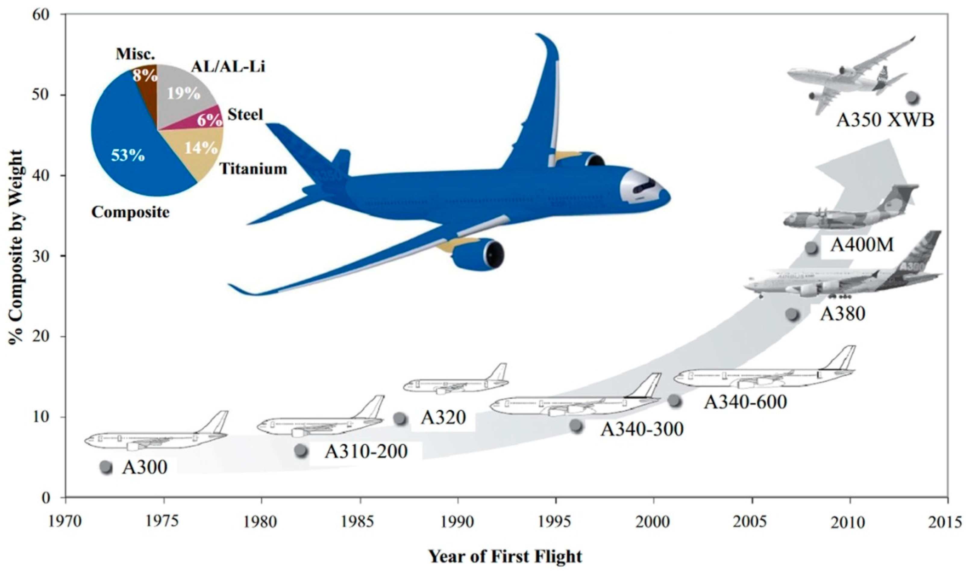
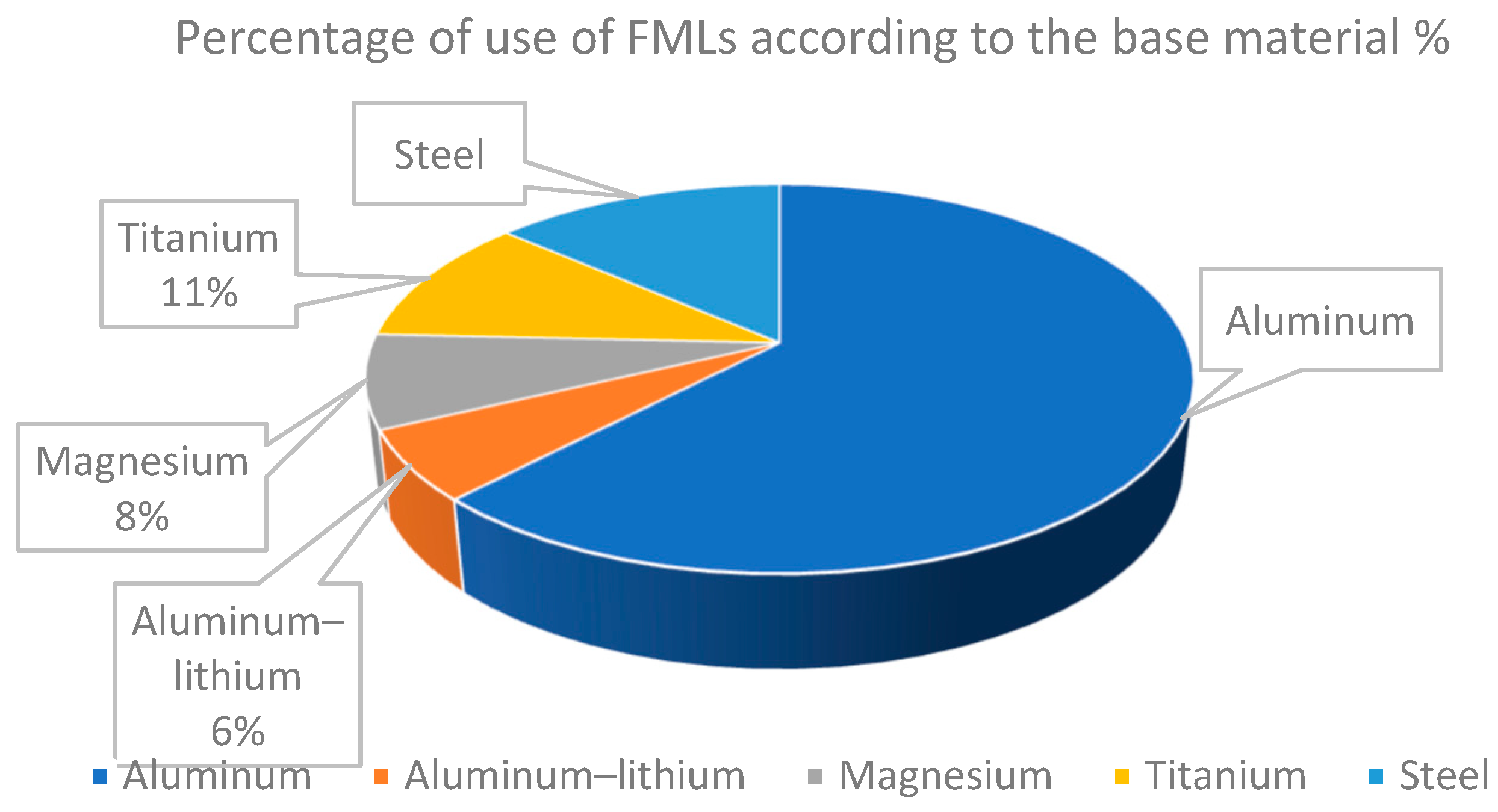
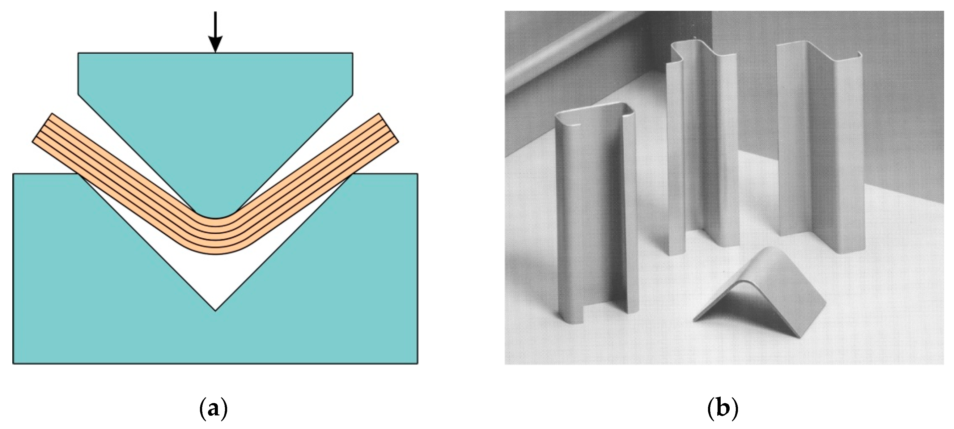
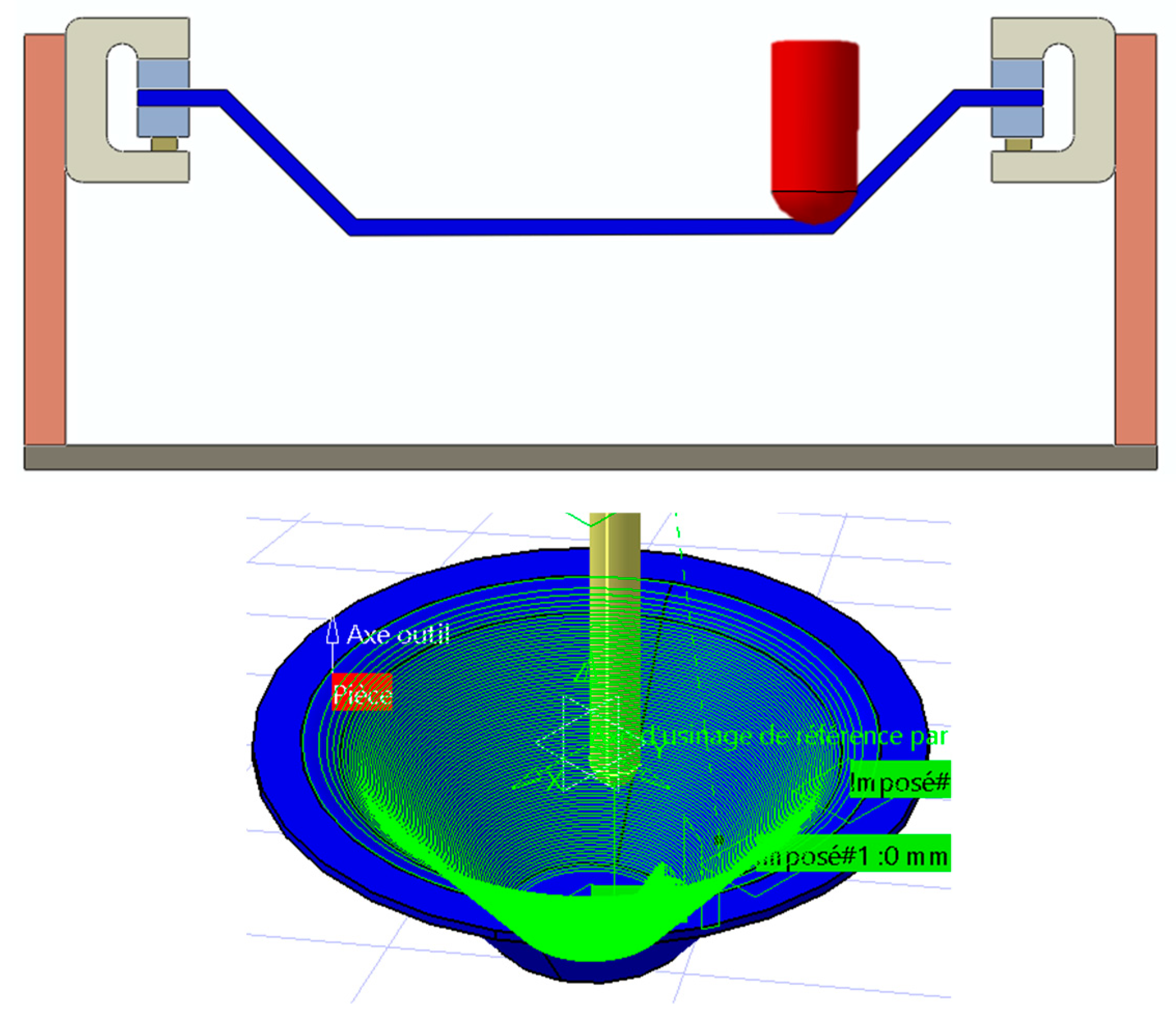
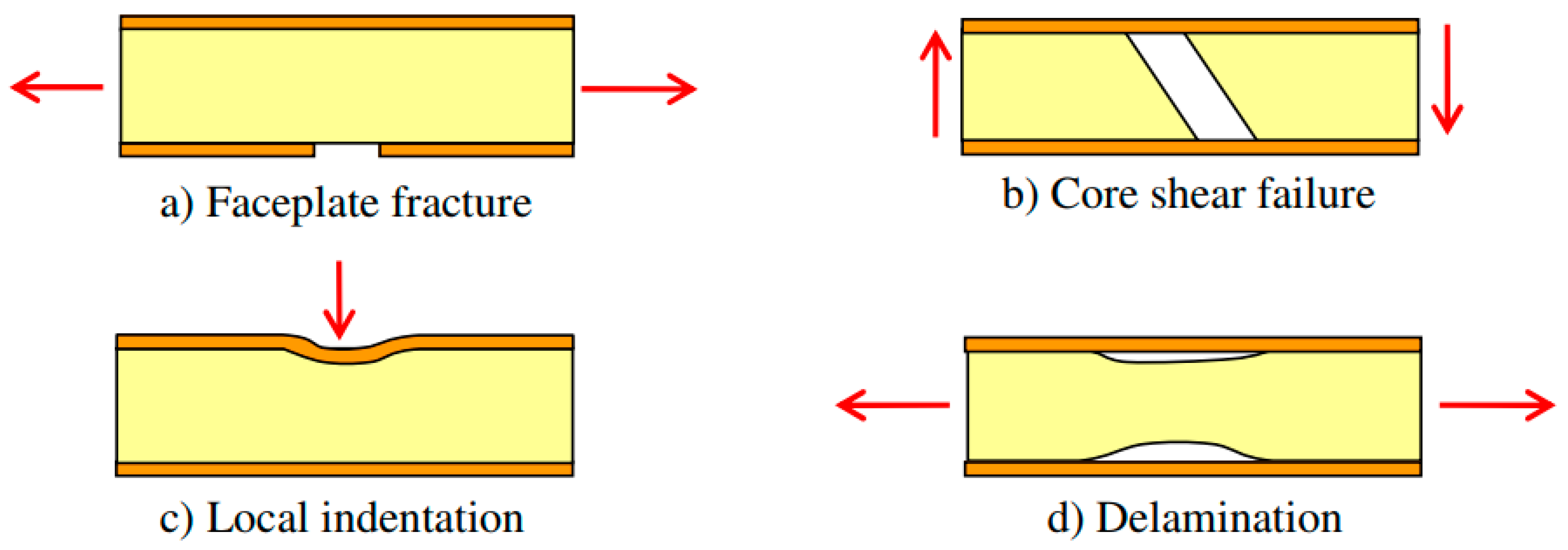
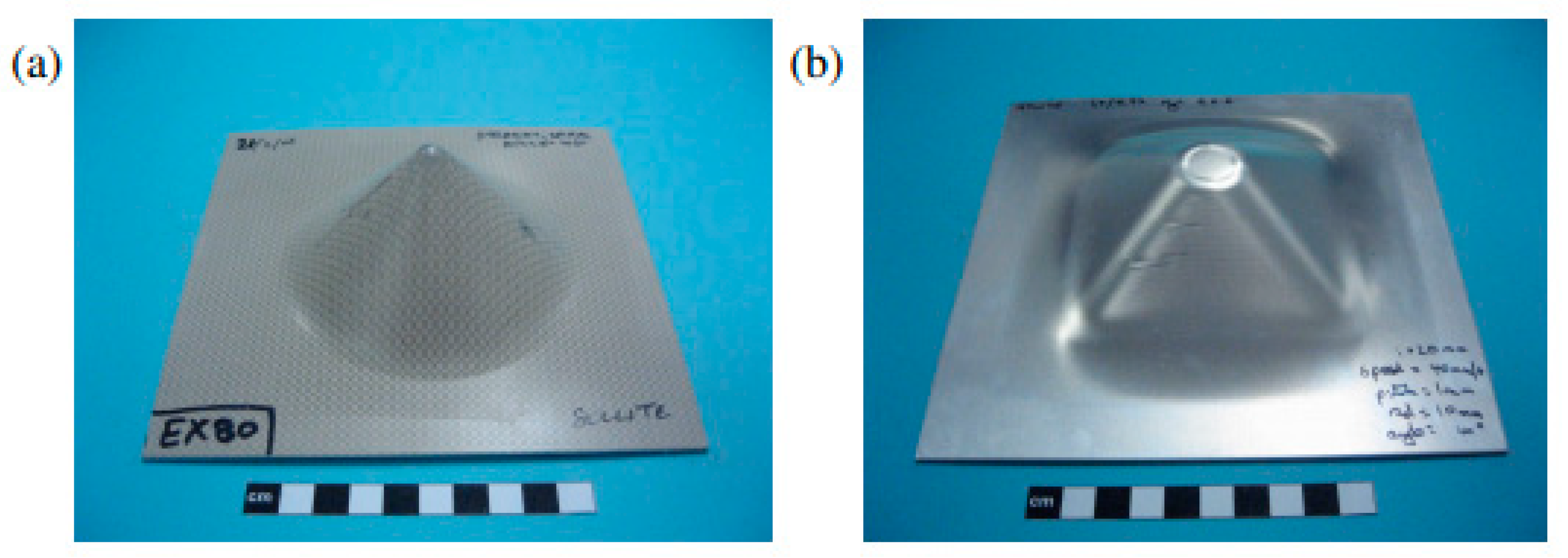
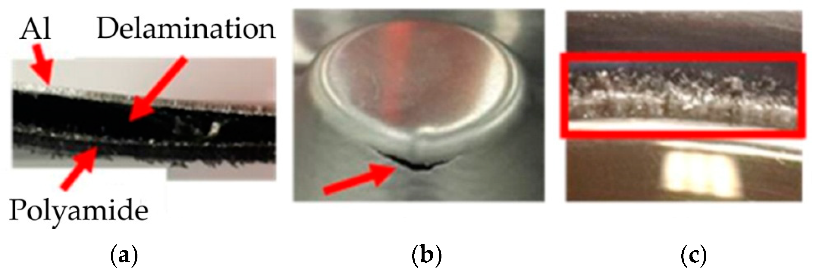
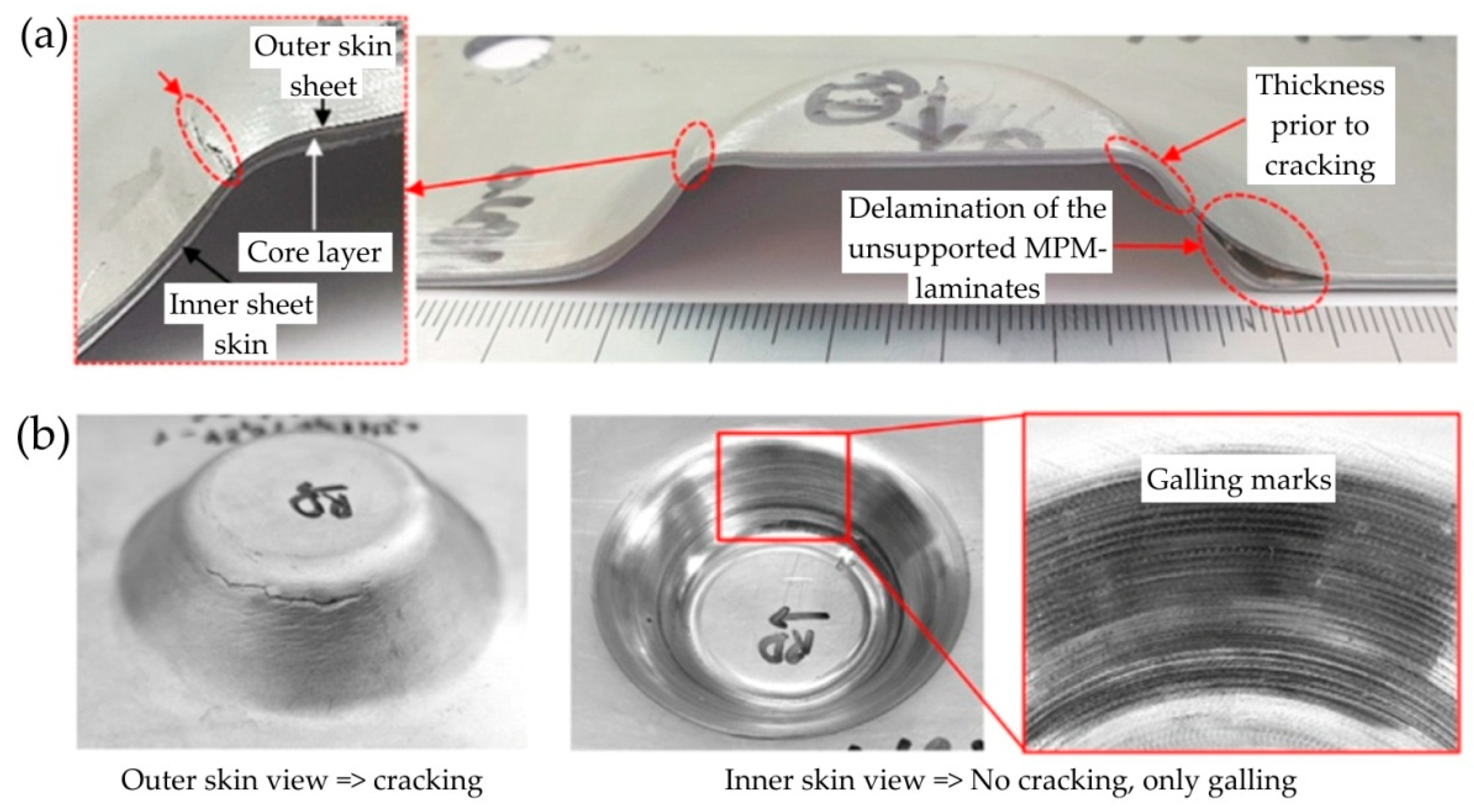
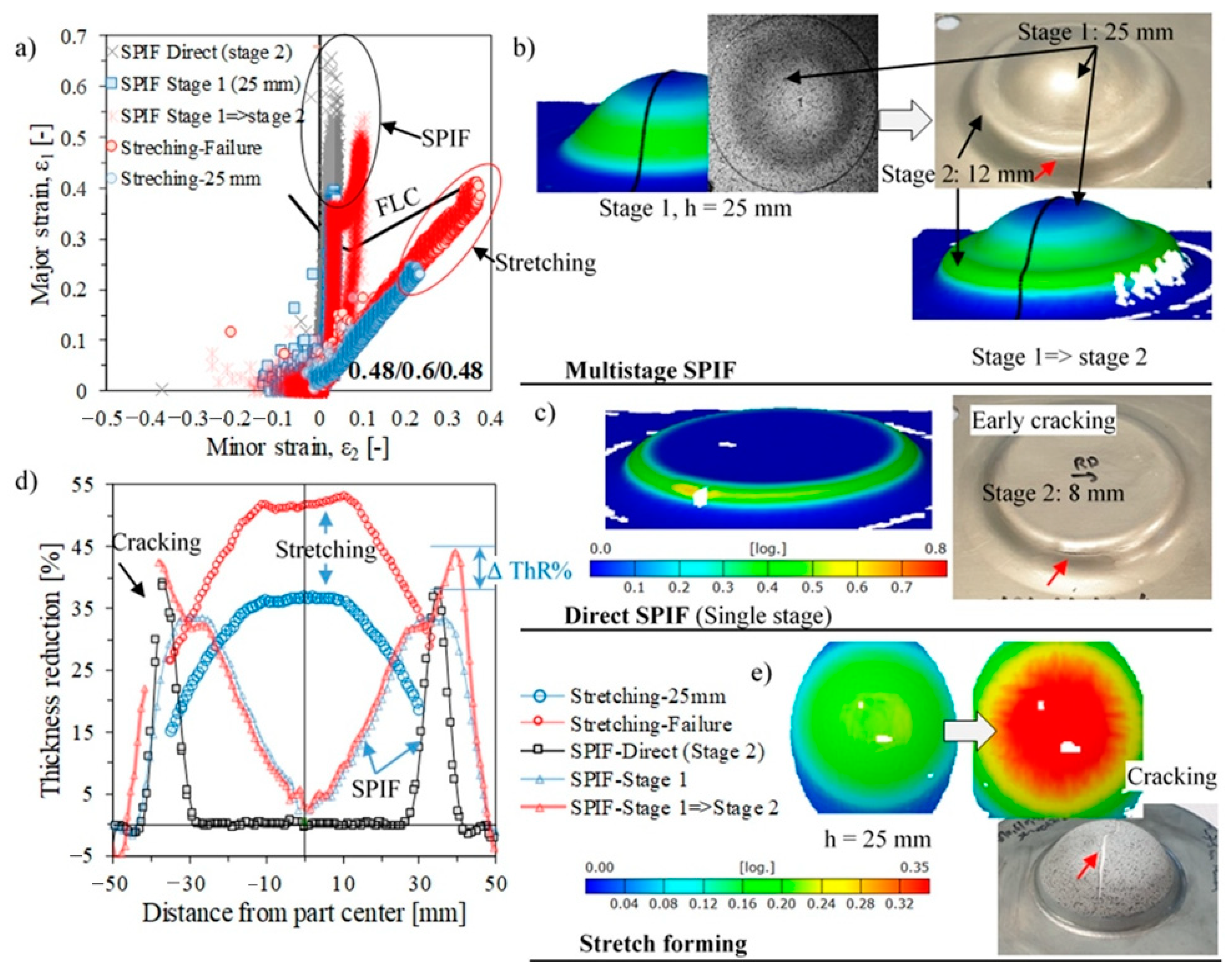
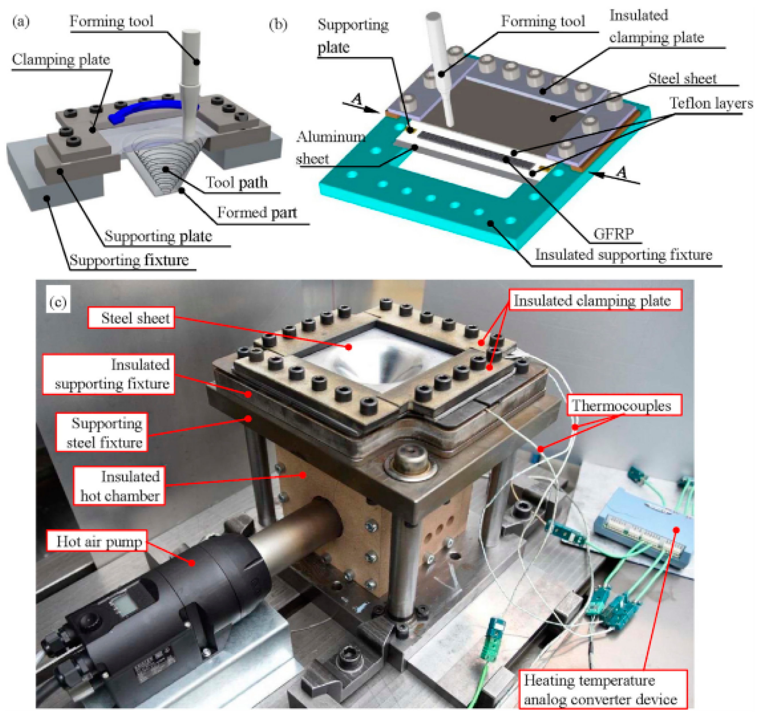
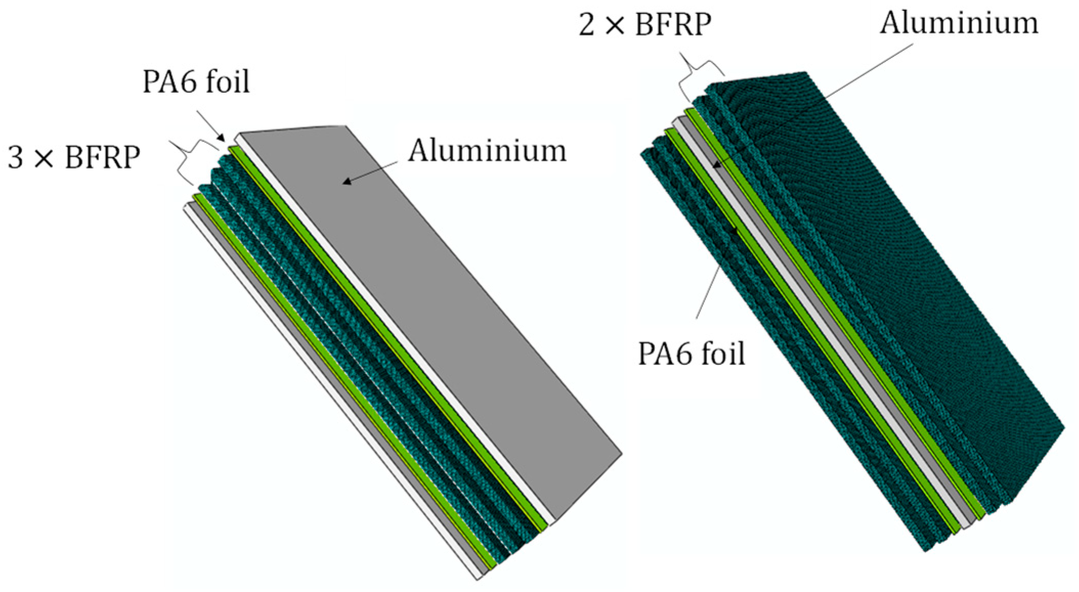
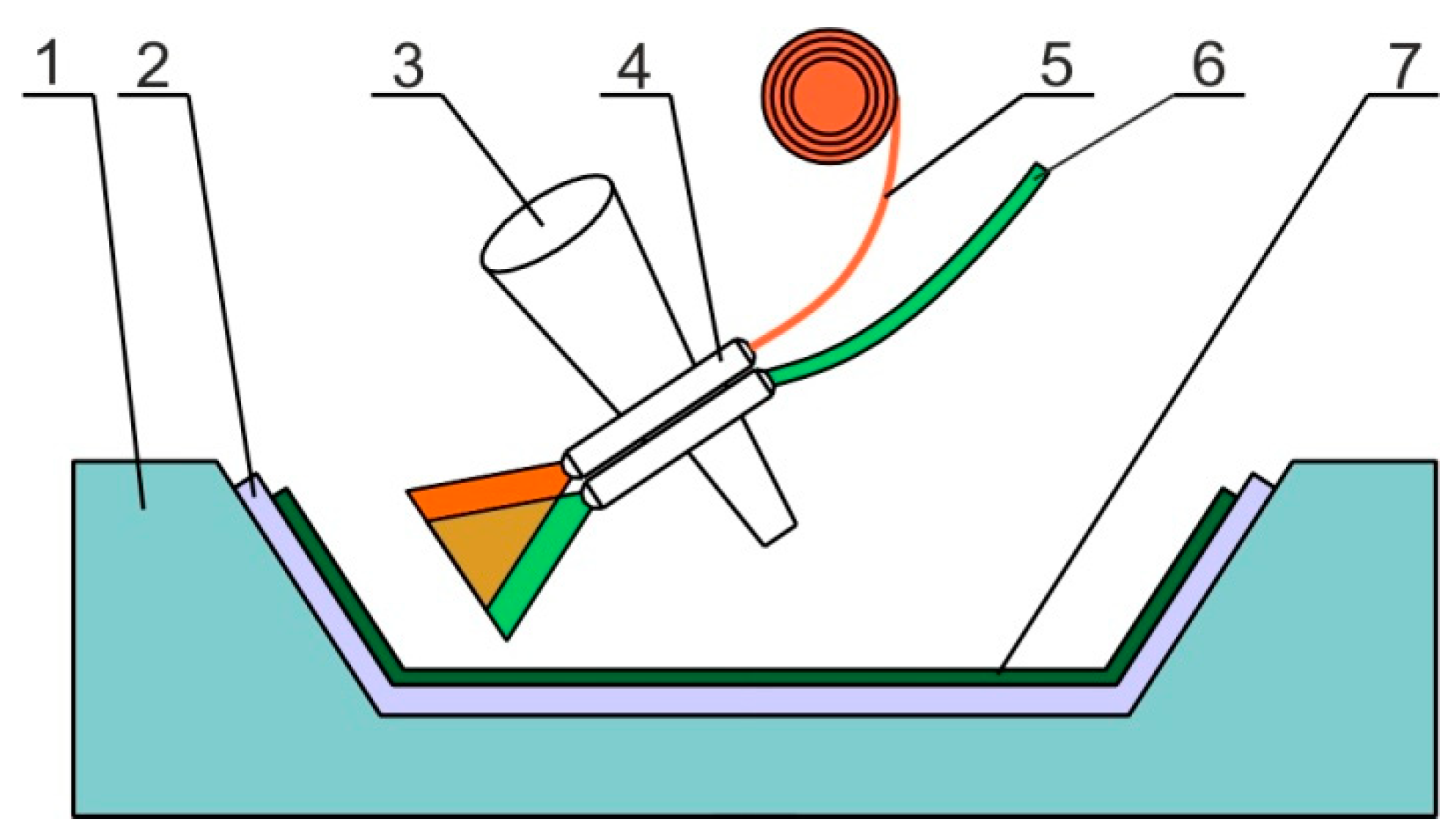
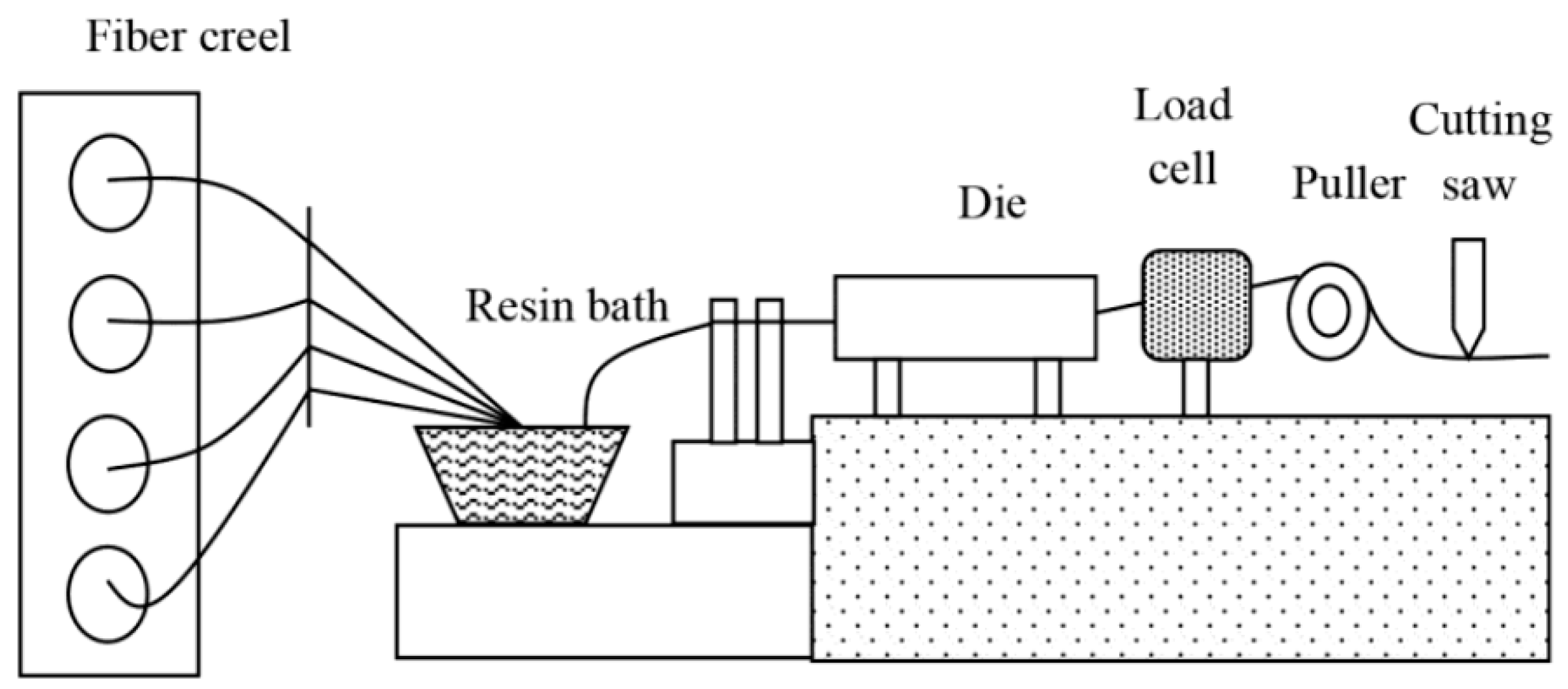
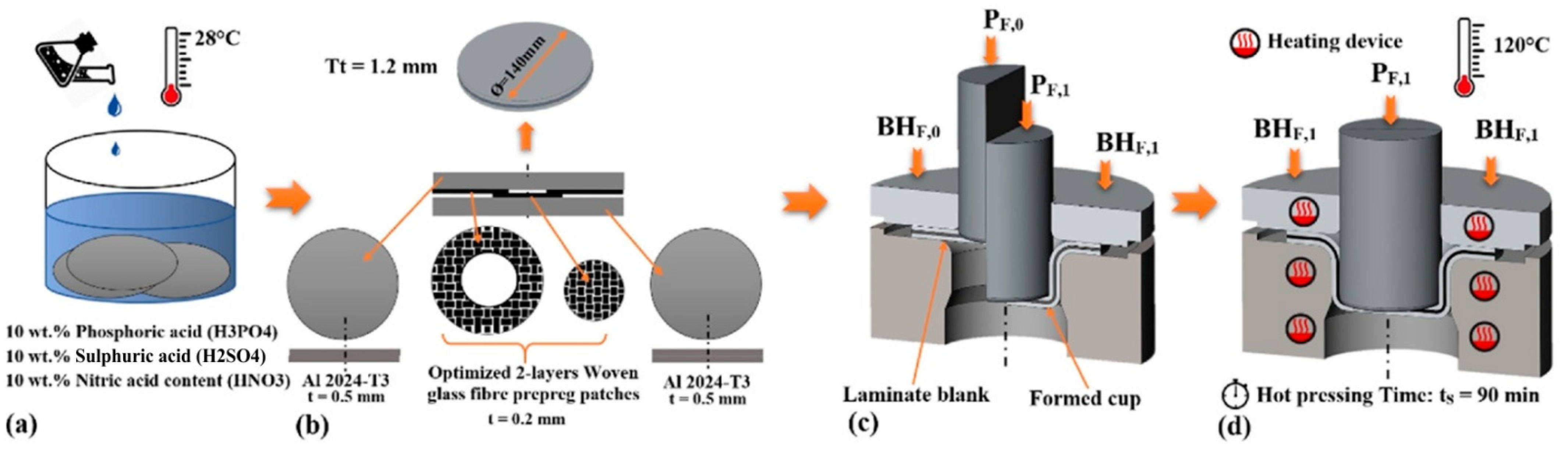
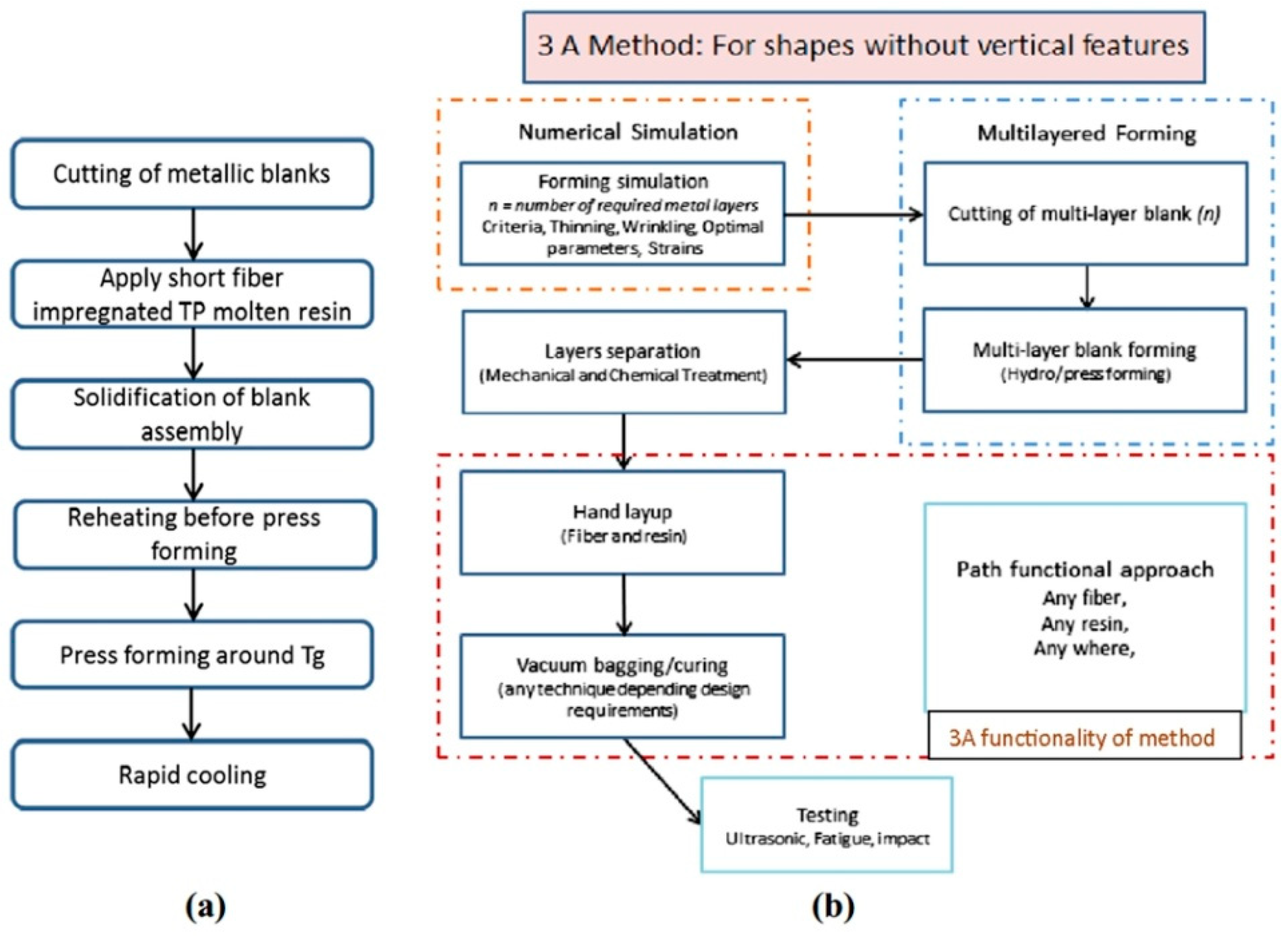
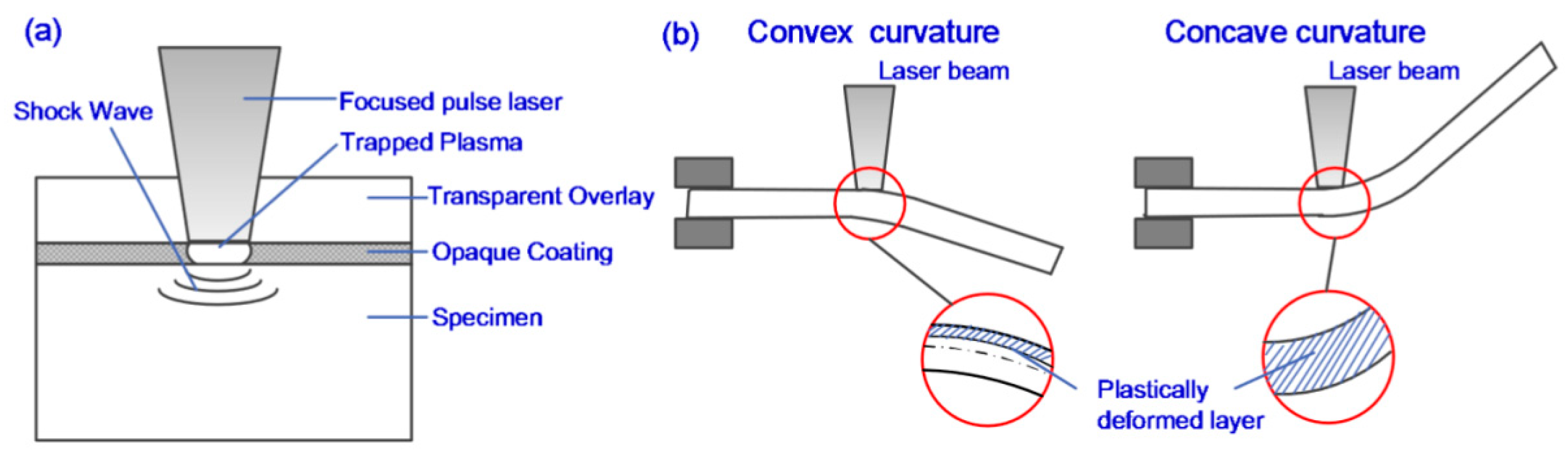
| Base Material | Alloy | Fibre Reinforced | References |
|---|---|---|---|
| Aluminum | Al 2024 | glass fibre reinforced/epoxy | [41,48,81,82,83,84,85,86,87,88,89,90,91,92,93,94,95,96,97,98,99,100] |
| carbon fibre reinforced/epoxy | [91,94,101,102,103] | ||
| glass fibre reinforced polypropylene (GFRP) | [104,105,106,107] | ||
| polypropylene fibre reinforced polypropylene (PP/PP) | [108] | ||
| thermoplastic nylon LFT with glass fibre reinforced | [109] | ||
| Nanoclay reinforced polypropylene and glass fibre | [110] | ||
| self-reinforced polypropylene (SRPP) | [106,111,112] | ||
| Al 8090 | glass fibre reinforced/epoxy | [113] | |
| Al 7075 | [114] | ||
| aramid fibre reinforced/epoxy | [115] | ||
| Al 1100 | aramid fibre reinforced polypropylene | [116] | |
| Al 5052 | [117,118] | ||
| carbon fibre reinforced/epoxy | [119,120] | ||
| self-reinforced polypropylene (SRPP) | [121] | ||
| Al 5005 | [122] | ||
| Al 6061 | [123] | ||
| glass fibre reinforced/epoxy | [114,124] | ||
| carbon fibre reinforced/epoxy | [125] | ||
| [126] | |||
| commercial aluminium | [127] | ||
| Al 7475 | [100] | ||
| Al 5083 | [128] | ||
| Al 6082 | [129] | ||
| Al 1060 | [97] | ||
| Al 1050 | [130,131] | ||
| Nanoclay reinforced polypropylene and glass fibre | [132] | ||
| LY12M | glass fibre reinforced/J272 | [133] | |
| carbon fibre reinforced/J272 | |||
| Al 5182 | glass fibre reinforced (PA6) | [134] | |
| Aluminium–lithium | Aluminium–lithium | glass fibre reinforced/epoxy | [135,136,137,138] |
| V-1469 | [139] | ||
| 2060 | [140] | ||
| Magnesium | AZ31 alloy | carbon fibre reinforced/epoxy | [5,141] |
| glass fibre reinforced polypropylene (GFPP) | [5] | ||
| glass fibre reinforced/epoxy | [6,100,142,143] | ||
| self-reinforced polypropylene (SRPP) | [111] | ||
| Magnesium | silicon carbide fibre reinforced | [144] | |
| Titanium | Ti 15-3-3-3 | carbon fibre reinforced polyetheretherketone (PEEK) | [145] |
| β-titanium alloy | glass fibre reinforced PEKK (GF/PEEK) | [146] | |
| grade-2 alloy | glass fibre reinforced polymer (GFRP) | [147] | |
| TA2 | carbon fibre reinforced/epoxy | [33,148] | |
| Ti-6A1-4V | [149] | ||
| glass fibre reinforced/epoxy | [7,150] | ||
| graphite fibre reinforced | [151] | ||
| graphite-fibre/epoxy and boron fibre/aluminum | [152] | ||
| thermoplastic fibre reinforced polymer | [153] | ||
| Steel | TS275 | glass fibre reinforced (PA6) | [134] |
| galvanized steel | [154] | ||
| galvanized steel | glass fibre reinforced polypropylene (GFPP) | [9] | |
| AISI 304 | glass fibre reinforced/epoxy | [155] | |
| carbon fibre reinforced/epoxy | [156] | ||
| steel | [157,158,159] | ||
| galvanized steel | [160] | ||
| DC03 | [161] | ||
| steel | self-reinforced polypropylene (SRPP) | [162] | |
| HC220Y | carbon fibre reinforced (PA6) | [163,164] | |
| HC260LAD + Z100 | glass or carbon fibre reinforced (PA6) | [165] |
| Metal | Matrix | Metal Surface Treatment | Reference |
|---|---|---|---|
| aluminium (grade not specified) | self-reinforcing polypropylene | 5% solution of sodium hydroxide for 5 min. | [172] |
| 2024-T3 aluminium alloy | epoxy | etching with chromic–sulphuric acid | [173] |
| 2024-T3 aluminium alloy | epoxy | anodising with phosphoric acid | [174] |
| 2024-T3 aluminium alloy | epoxy | etching with chromic acid followed by anodising with phosphoric acid | [175] |
| 35K cold-drawn steel | epoxy | 5% etching solution for 10 min. | [176] |
| DP800 hot-dip galvanised steel | PA6 | galvannealing | [154] |
| Ti-6Al-4V titanium alloy | epoxy | grit blasting | [177] |
| Ti-6A1-4V titanium alloy | polyimide | surface treatment with Pasa-Jell 107 | [151] |
| β-titanium alloy | woven S-glass fibre reinforced PEKK | laser treatment | [146] |
| Ti-15–3-3–3 alloy | polietheroimid | wiping with ethanol | [178] |
| Pure titanium TA2 | polyimide | sand blasting | [179] |
| AZ31 magnesium alloy | glass fibre reinforced polypropylene | abrading with a 1200 sandpaper and cleaning with acetone | [5] |
| AZ31 magnesium alloy | epoxy | grit blasting | [180,181] |
| magnesium | epoxy | abrading and solvent wipe treatment | [182] |
| tPA (mm) | tAl (mm) | Δz (mm) | Failure Mode | Formability |
|---|---|---|---|---|
| <1.58 | 0.8 | 0.2 | delamination | increases |
| 1.58 | metal tearing | maximum | ||
| >1.58 | metal tearing | slightly reduced | ||
| <1.98 | 0.4 | delamination | increases | |
| 1.98 | metal tearing | maximum | ||
| >1.98 | metal tearing | slightly reduced | ||
| <1.58 | 1 | 0.2 | delamination | increases |
| 1.58 | metal tearing | maximum | ||
| >1.58 | galling | slightly reduced | ||
| <1.98 | 0.4 | delamination | increases | |
| 1.98 | metal tearing | maximum | ||
| 2.38 | galling | slightly reduced |
| Method | Advantage | Disadvantage |
|---|---|---|
| Hand lay-up | Low cost of tooling [364,365] The process is simple [364] Large, complex parts can be formed [365] Flexible design [364] Production technology is easy to master [365] Any combination of fibres and matrix materials can be used [364] | The process is time-consuming [364] Powder and bad smells are involved in the production environment [365] Quality of the final product depends on highly skilled manpower [364] The process is labour intensive [366] |
| Spray lay-up | Suitable for small- to medium-volume parts [364] Low-cost tooling [364] | It is difficult to control the fibre volume fraction [364] There is difficulty in removing trapped air from the moulding [365] The process does not provide a good surface finish [364] |
| RTM | Complex parts can be fabricated [307,309,366] Higher volume outputs and much lower cycle times than other methods [308,366] Production of smooth-surfaced parts on both inner and outer surfaces of the mould [307,308,366]. Components can be produced up to 5–20 times faster compared with open moulding techniques [367] | High production volumes require offset high tooling costs [307,308,367] Difficult to effectively improve the fibre volume content of the product [367] The size of the part is limited by the mould [308,367]. |
| LRTM | Produces finished surfaces on both sides of the part [318,368] Improved process control enhance of dimensional stability [319,368] Significant saving in tooling costs as it only requires a single-piece mould [318,368] Cost-effective to manufacture large panels such as ship’s hulls [368,369] Fabrication of large composite panels takes place at room temperature [319,370] Scalability for large structures [320,371] Toughened infusion resins can be used [371] | Compared with conventional RTM, LRTM is characterised by limited compaction of the reinforcement, a limited injection pressure, and lower dimensional accuracy [318,319,320,372] Trial and error development can prove costly and ineffective [313,373] |
| Autoclave process | Large components can be fabricated [364] Good surface finish [364] | High initial cost of equipment [364] High cost of maintenance [364] Not suitable for small products [364] |
| Pultrusion | Requires low labour [348,349,350,364] Good surface finish [348,364] Process is economical [364] | High cost of heated die [346,350,353,364] Limited to constant or near-constant cross-section components [346,349,364] |
| Filament winding | Complex fibre patterns can be used [355,356,364] Good resin distribution in products [364] A favourable fibre orientation can be obtained [358,359] Process can be highly automated [355,356,357,358] | Process is limited to convex shaped components [358,359] The external surface of the component is not smoothly finished [360,361,364] High cost of mandrell [355,356,364] |
Publisher’s Note: MDPI stays neutral with regard to jurisdictional claims in published maps and institutional affiliations. |
© 2021 by the authors. Licensee MDPI, Basel, Switzerland. This article is an open access article distributed under the terms and conditions of the Creative Commons Attribution (CC BY) license (https://creativecommons.org/licenses/by/4.0/).
Share and Cite
Trzepieciński, T.; Najm, S.M.; Sbayti, M.; Belhadjsalah, H.; Szpunar, M.; Lemu, H.G. New Advances and Future Possibilities in Forming Technology of Hybrid Metal–Polymer Composites Used in Aerospace Applications. J. Compos. Sci. 2021, 5, 217. https://doi.org/10.3390/jcs5080217
Trzepieciński T, Najm SM, Sbayti M, Belhadjsalah H, Szpunar M, Lemu HG. New Advances and Future Possibilities in Forming Technology of Hybrid Metal–Polymer Composites Used in Aerospace Applications. Journal of Composites Science. 2021; 5(8):217. https://doi.org/10.3390/jcs5080217
Chicago/Turabian StyleTrzepieciński, Tomasz, Sherwan Mohammed Najm, Manel Sbayti, Hedi Belhadjsalah, Marcin Szpunar, and Hirpa G. Lemu. 2021. "New Advances and Future Possibilities in Forming Technology of Hybrid Metal–Polymer Composites Used in Aerospace Applications" Journal of Composites Science 5, no. 8: 217. https://doi.org/10.3390/jcs5080217